Open Gear Lubrication Paper - RJ Mellor Gear Lubrication Paper.pdf · 2016-03-11 · continuing...
4
Lubrication has, and always will have, a two-fold problem, the choice of lubricant and the means of application. An incorrect choice in either direction will ultimately lead to a serious malfunction. Over the years, lubricant and system manufacturers have been reluctant to become involved in each other's discipline. This attitude has seriously retarded the progress that should have been made in providing the market with sound solutions to the continuing problem of open gear lubrication. A recent study (Figure 1) of 55 girth-gear drive tooth flank failures provided some extremely interesting results. Some 18.2% of failures were directly attributed to lubrication problems, with 38.5% an amalgam of all areas evaluated. What is clear is that lubrication does play a significant part in ensuring gear trains achieve their design life, therefore it is essential that the correct choice of lubricant and means of application be made. To provide correct lubrication it is fundamental that the gear train is not only correctly aligned to itself, but also to the coupling gearbox and motor. Whilst lubricants will provide some emergency cover due to the solid EP content, they will not overcome mechanical problems caused by design faults or misalignment. Unlike a normal rotating bearing where hydrostatic or hydrodynamic lubrication is readily achieved, the surface finish and the slow rotational speed of the open gears culminate in a sliding rolling sliding action. This does not permit the surfaces to be completely separated by a wedge of lubricant, therefore only boundary lubrication, or at best mixed friction, will be achieved. During the meshing of a gear train (Figure 2) the gear teeth are in contact with each other over a very small area at any given time. Therefore, whilst the teeth are in mesh, the point of contact moves in the direction from root to crest of the tooth on the driving gear wheel, and from crest to root on the driven gear wheel. This confirms that the movement is seen to be sliding rolling sliding. 38.5 3.5 5.6 9.1 21.7 3.5 7.2 10.9 0 10 20 30 40 PERCENTAGE Unclear Insufficient Lubricant Supply Carrying Capacity Axial/Radial Run Out >18% of failures >18% of failures directly attributed to directly attributed to lubrication problems lubrication problems Figure 1.Causes of Tooth Flank Figure 1.Causes of Tooth Flank Damage Based on 55 Girth Damage Based on 55 Girth Gear Drives Gear Drives Figure 2. Meshing of a gear train Problems with Bitumen/Solvent Based Products Open gear service lubricants based on bitumen and solvents have been the standard for many years, and are often classed as carcinogenic with the apparent viscosity of the grease totally dependent on temperature and temperature change. For example, at 50 to 80oC it drips off, at 15oC the material hardens, and depending on quality, at 5 to 8oC it solidifies. This behaviour seriously affects the film thickness and subsequent strength. Therefore, large volumes of lubricant will be required with poor results. Solvents and bituminous products are synonymous with operational difficulties concerning the spray system, with problems such as: Spray pattern varies with geometry and density. Difficulty in removing waste grease. Grease compacting in the tooth root causing high horizontal vibrations. Changes in temperature seriously affect the apparent viscosity of the grease, causing pumping problems. Unable to view the tooth flank condition with a strobe light, when gears are in operation. R J Mellor & Co Ltd Open Gear Lubrication Open Gear Lubrication Open Gear Lubrication Open Gear Lubrication R J Mellor Managing Director Open Gear Lubrication Open Gear Lubrication Open Gear Lubrication Open Gear Lubrication Open Gear Lubrication Open Gear Lubrication Open Gear Lubrication Open Gear Lubrication R J Mellor Managing Director Specialist Lubrication Engineers
Transcript of Open Gear Lubrication Paper - RJ Mellor Gear Lubrication Paper.pdf · 2016-03-11 · continuing...
Lubrication has, and always will have, a two-fold problem, the choice of lubricant and the means of application. An incorrect choice in either direction will ultimately lead to a serious malfunction. Over the years, lubricant and system manufacturers have been reluctant to become involved in each other's discipline. This attitude has seriously retarded the progress that should have been made in providing the market with sound solutions to the continuing problem of open gear lubrication.
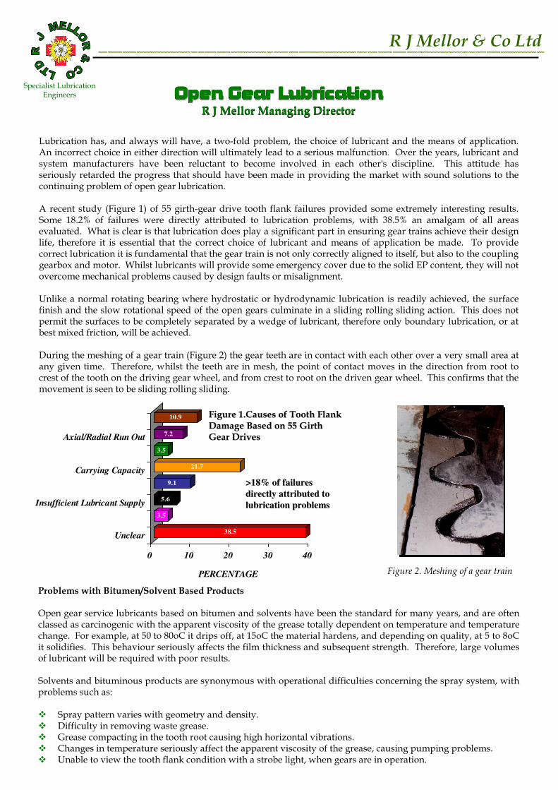
A recent study (Figure 1) of 55 girth-gear drive tooth flank failures provided some extremely interesting results. Some 18.2% of failures were directly attributed to lubrication problems, with 38.5% an amalgam of all areas evaluated. What is clear is that lubrication does play a significant part in ensuring gear trains achieve their design life, therefore it is essential that the correct choice of lubricant and means of application be made. To provide correct lubrication it is fundamental that the gear train is not only correctly aligned to itself, but also to the coupling gearbox and motor. Whilst lubricants will provide some emergency cover due to the solid EP content, they will not overcome mechanical problems caused by design faults or misalignment.
Unlike a normal rotating bearing where hydrostatic or hydrodynamic lubrication is readily achieved, the surface finish and the slow rotational speed of the open gears culminate in a sliding rolling sliding action. This does not permit the surfaces to be completely separated by a wedge of lubricant, therefore only boundary lubrication, or at best mixed friction, will be achieved.
During the meshing of a gear train (Figure 2) the gear teeth are in contact with each other over a very small area at any given time. Therefore, whilst the teeth are in mesh, the point of contact moves in the direction from root to crest of the tooth on the driving gear wheel, and from crest to root on the driven gear wheel. This confirms that the movement is seen to be sliding rolling sliding.
38.5
3.5
5.6
9.1
21.7
3.5
7.2
10.9
0 10 20 30 40
PERCENTAGE
Unclear
Insufficient Lubricant Supply
Carrying Capacity
Axial/Radial Run Out
>18% of failures >18% of failures
directly attributed to directly attributed to
lubrication problemslubrication problems
Figure 1.Causes of Tooth Flank Figure 1.Causes of Tooth Flank Damage Based on 55 Girth Damage Based on 55 Girth Gear DrivesGear Drives
Figure 2. Meshing of a gear train
Problems with Bitumen/Solvent Based Products
Open gear service lubricants based on bitumen and solvents have been the standard for many years, and are often classed as carcinogenic with the apparent viscosity of the grease totally dependent on temperature and temperature change. For example, at 50 to 80oC it drips off, at 15oC the material hardens, and depending on quality, at 5 to 8oC it solidifies. This behaviour seriously affects the film thickness and subsequent strength. Therefore, large volumes of lubricant will be required with poor results.
Solvents and bituminous products are synonymous with operational difficulties concerning the spray system, with problems such as:
� Spray pattern varies with geometry and density.� Difficulty in removing waste grease.� Grease compacting in the tooth root causing high horizontal vibrations.� Changes in temperature seriously affect the apparent viscosity of the grease, causing pumping problems.� Unable to view the tooth flank condition with a strobe light, when gears are in operation.
R J Mellor & Co Ltd
Open Gear LubricationOpen Gear LubricationOpen Gear LubricationOpen Gear LubricationR J Mellor Managing Director
Open Gear LubricationOpen Gear LubricationOpen Gear LubricationOpen Gear LubricationOpen Gear LubricationOpen Gear LubricationOpen Gear LubricationOpen Gear LubricationR J Mellor Managing Director
Specialist LubricationEngineers
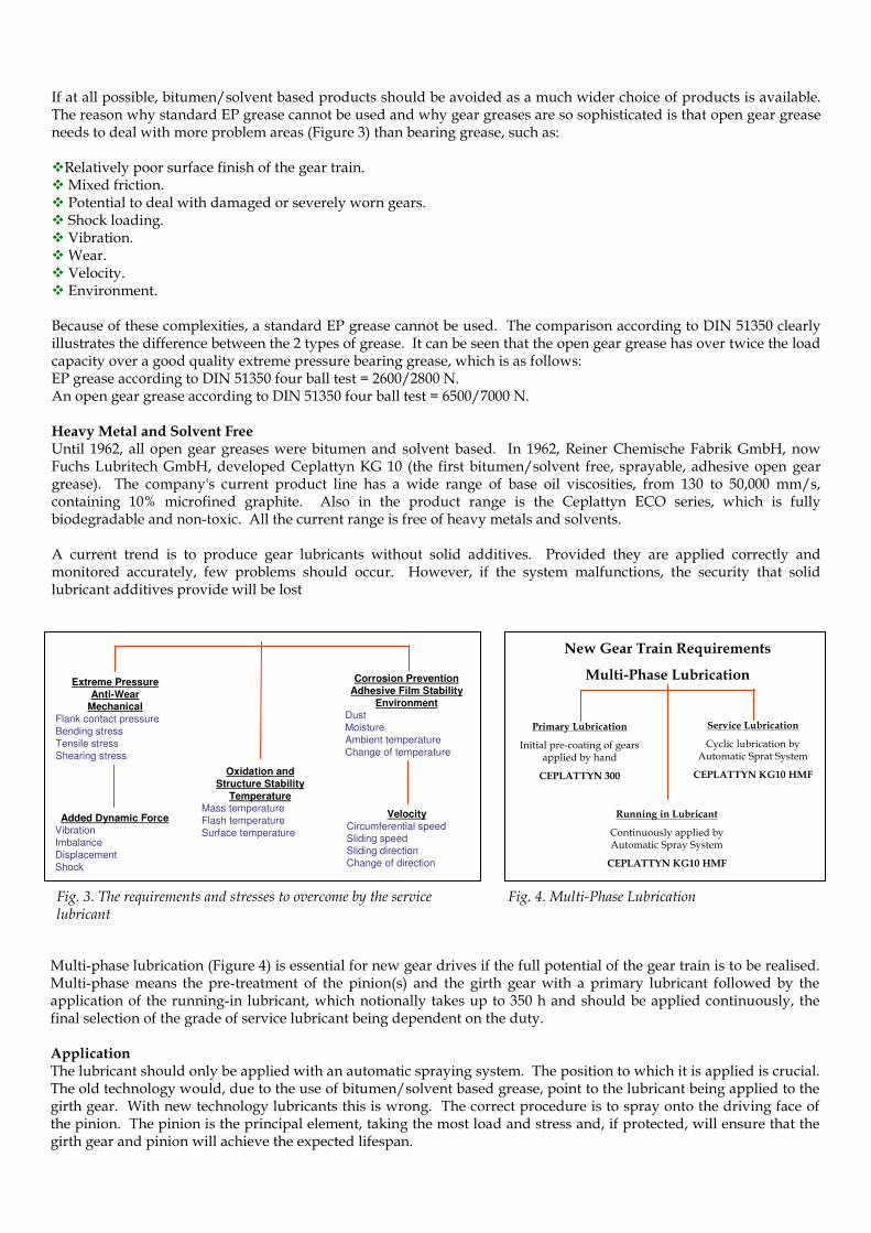
If at all possible, bitumen/solvent based products should be avoided as a much wider choice of products is available. The reason why standard EP grease cannot be used and why gear greases are so sophisticated is that open gear grease needs to deal with more problem areas (Figure 3) than bearing grease, such as:
�Relatively poor surface finish of the gear train.� Mixed friction.� Potential to deal with damaged or severely worn gears.� Shock loading.� Vibration.� Wear.� Velocity.� Environment.
Because of these complexities, a standard EP grease cannot be used. The comparison according to DIN 51350 clearly illustrates the difference between the 2 types of grease. It can be seen that the open gear grease has over twice the load capacity over a good quality extreme pressure bearing grease, which is as follows:EP grease according to DIN 51350 four ball test = 2600/2800 N.An open gear grease according to DIN 51350 four ball test = 6500/7000 N.
Heavy Metal and Solvent FreeUntil 1962, all open gear greases were bitumen and solvent based. In 1962, Reiner Chemische Fabrik GmbH, now Fuchs Lubritech GmbH, developed Ceplattyn KG 10 (the first bitumen/solvent free, sprayable, adhesive open gear grease). The company's current product line has a wide range of base oil viscosities, from 130 to 50,000 mm/s, containing 10% microfined graphite. Also in the product range is the Ceplattyn ECO series, which is fully biodegradable and non-toxic. All the current range is free of heavy metals and solvents.
A current trend is to produce gear lubricants without solid additives. Provided they are applied correctly and monitored accurately, few problems should occur. However, if the system malfunctions, the security that solid lubricant additives provide will be lost
Multi-phase lubrication (Figure 4) is essential for new gear drives if the full potential of the gear train is to be realised. Multi-phase means the pre-treatment of the pinion(s) and the girth gear with a primary lubricant followed by the application of the running-in lubricant, which notionally takes up to 350 h and should be applied continuously, the final selection of the grade of service lubricant being dependent on the duty.
ApplicationThe lubricant should only be applied with an automatic spraying system. The position to which it is applied is crucial. The old technology would, due to the use of bitumen/solvent based grease, point to the lubricant being applied to the girth gear. With new technology lubricants this is wrong. The correct procedure is to spray onto the driving face of the pinion. The pinion is the principal element, taking the most load and stress and, if protected, will ensure that the girth gear and pinion will achieve the expected lifespan.
Extreme Pressure
Anti-WearMechanical
Flank contact pressure
Bending stress
Tensile stress
Shearing stress
Added Dynamic ForceVibration
Imbalance
Displacement
Shock
Oxidation and
Structure Stability
TemperatureMass temperature
Flash temperature
Surface temperature
Velocity
Circumferential speedSliding speed
Sliding direction
Change of direction
Corrosion Prevention
Adhesive Film Stability
EnvironmentDust
Moisture
Ambient temperature
Change of temperature
Fig. 3. The requirements and stresses to overcome by the servicelubricant
New Gear Train Requirements
Multi-Phase Lubrication
Primary Lubrication
Initial pre-coating of gears applied by hand
CEPLATTYN 300
Service Lubrication
Cyclic lubrication by Automatic Sprat System
CEPLATTYN KG10 HMF
Running in Lubricant
Continuously applied by Automatic Spray System
CEPLATTYN KG10 HMF
Fig. 4. Multi-Phase Lubrication

The spray head should produce a fan-shape overlapping spray pattern (not round, Figure 6), and be positioned 150 to 200 mm from the tooth flank. This distance can be increased marginally with lubricants having a base oil viscosity greater than 2500 mm/s. The spray pattern must cover the total tooth flank area from tip to root (Figure 7).
Fig. 5. Example of girth gear lubrication Fig. 6. Examples of incorrectly chosen and positioned round spray heads resulting in cavitation erosion. resulting in cavitation erosion.
Fig. 7 Pinion gear drive tooth flank
Fig. 8 Direct Oil Feed System Fig. 12 Spray Panel of single line progressive spray system
Fig. 11 Single line modular progressive distributor
Fig. 9 Dual line modular distributor
Fig. 10 Single line positive displacement dispensing valve
Systems
There are several types of systems that have been used over the years:� Oil bath.� Direct feed.� Dual line.� Single line positive displacement.� Single line progressive is our preferred choiceAll these systems, with the exception of the oil bath, supply lubricant under pressure from a pump, dripping or spraying lubricant onto girth gear/pinion or where girth gear and pinion mesh.
Oil Bath
The oil bath is where the girth gear is immersed in lubricant, and is subsequently used to transfer lubricant to the pinion. The oil bath is arguably the most successful method of lubrication if the following parameters are met:
�It is correctly sealed from the environment and the process product.�A high quality viscose oil with a high level of extreme pressure additive is employed to effectively deal with mixed friction.

Direct Feed (Figure 8)
The direct feed system is probably the oldest in use and normally drips lubricant onto girth gear or pinion. Whilst it can be used with spray heads, this is rarely the case. The problem experienced with this type of system is uneven distribution of lubricant, which results in a poor film thickness with little or no control of flow and with limited monitoring facilities.
Dual Line (Figure 9)
The dual line system is probably the most widely used means of application; however, there are potential problem areas, such as 2 lubricant supply lines, reversing valve to change lubricant from the first to the second supply line and an air/grease mixing valve. Electronic monitoring of each of the distribution valves is possible but expensive. This type of system is designed to monitor basically the operating pressure and not the flow of lubricant.
Single Line Positive Displacement (Figure 10)
Here the lubricant is sprayed onto girth or pinion gear under pump pressure to the spray heads. At the end of the lubrication cycle, the pressure in the feed line is relieved via a valve at the pump, allowing the grease pressure to relax and the spring inside the injector to recharge the injector in preparation for the next cycle.A potentially serious problem is the recharging of the injector which, due to the high base oil viscosity of the lubricants used today, often fails to occur. Furthermore, monitoring and maintenance are expensive.
Single Line Progressive (Figure 11)
This system will provide the most effective lubricant coverage of the tooth flank handling all currently known lubricants. It is easy to control and maintain lubricant flow, and will provide first class monitoring facilities. This is the system of of our choice. The system design should consider the following parameters:� Reliability.� Robust construction.� Easily installed.� Simple design.� Easy to maintain.� Absolute control of the lubricant dispensed.� Complete monitoring of the system operation (Figure 12).� Tamper-proof settings.
The lubrication system (Figure 13) should spray lubricant onto the driving face of the pinion (not the girth gear) and provide complete control of the lubricant dispensed with tamper-proof settings. The following features should be provided as a minimum requirement for any spray system:
� Indication of no grease flow to all the sprayheads.� Indication of no air flow (not pressure) to all the sprayheads.� Indication of low lubricant level in the grease container.� Indication of volume of product used and/or completed lubricant cycles.� Volt-free contacts that will allow the alarm functions to be remotely monitored.
ConclusionIt is important to remember that lubrication is a two-fold problem, the choice of lubricant and the correct means of application. A correct decision will achieve the maximum results from the gear train, whereas an unwise choice will result in high maintenance and production costs.