IT Services Network Infrastructure Specification Services... · Network Infrastructure...
27
Network Infrastructure Specification 10.8 Front Cover IT Services Network Infrastructure Specification Requirements Document for Project Managers and Contractors Revision: 10.8 Date: 17 th January 2017
Transcript of IT Services Network Infrastructure Specification Services... · Network Infrastructure...

Network Infrastructure Specification 10.8 Front Cover
IT Services Network Infrastructure Specification
Requirements Document for Project Managers and
Contractors
Revision: 10.8
Date: 17th January 2017

Network Infrastructure Specification 10.8 frontispiece
Document History
Title IT Services Network Infrastructure Specification:
Requirements Document for Project Managers and Contractors
Version 10.8
Date of issue 17th January 2017
Date of expiry 17th January 2017
Owner Gary Borwell, IT Services
Confidentiality General Release
Copyright University of York
Network Infrastructure Specification 10.8 Contents
Contents 1. General requirements................................................................................................................. 5
1.1 Diverse connectivity ............................................................................................................ 5
1.2 Data outlet type and distribution ...................................................................................... 5
1.3 Wireless infrastructure ........................................................................................................ 5
1.4 Cabling etc. requirements ................................................................................................... 5
1.5 Connection of equipment .................................................................................................... 6
2. External services .......................................................................................................................... 6
2.1 Duct routes and construction ............................................................................................. 6
2.2 Duct access ............................................................................................................................ 6
2.3 External cabling and micro ducts ...................................................................................... 7
3. Wiring centres .............................................................................................................................. 8
3.1 Connectivity .......................................................................................................................... 8
3.2 Access ..................................................................................................................................... 8
3.3 General design and layout .................................................................................................. 8
3.4 Power and environment ...................................................................................................... 9
3.5 Signage ................................................................................................................................... 9
4. Data outlet distribution ........................................................................................................... 10
4.1 Design and planning ......................................................................................................... 10
4.2 Installation ........................................................................................................................... 10
4.3 Office areas .......................................................................................................................... 11
4.4 Meeting and seminar rooms ............................................................................................. 11
4.5 Open and communal areas ............................................................................................... 11
4.6 Residential areas ................................................................................................................. 12
4.7 Plant and store rooms ........................................................................................................ 12
4.8 Wireless ............................................................................................................................... 12
5. Data cabinets .............................................................................................................................. 14
5.1 Preferred type ..................................................................................................................... 14
5.2 Layout .................................................................................................................................. 14
5.3 Installation ........................................................................................................................... 18
6. Labelling ..................................................................................................................................... 20
6.1 External cabling .................................................................................................................. 20
6.2 Fibre optic patch panels .................................................................................................... 20
6.3 Data outlets ......................................................................................................................... 20
6.4 Patch panels ........................................................................................................................ 21
7. Acceptance testing and documentation ................................................................................ 22
7.1 Structured cabling .............................................................................................................. 22
7.2 Fibre optic installations ..................................................................................................... 22
8. Connected equipment .............................................................................................................. 23
8.1 Registration ......................................................................................................................... 23

Network Infrastructure Specification 10.8 Contents
8.2 Prohibitions ......................................................................................................................... 23
9. Approved manufacturers and cabling systems ................................................................... 24
9.1 Augmented Category 6 (Cat.6A) infrastructure ............................................................ 24
9.2 Enhanced Category 5 (Cat.5e) infrastructure ................................................................. 24
9.3 Blown fibre components ................................................................................................... 24
10. Compliance ................................................................................................................................. 25
10.1 Legislative compliance .................................................................................................. 25
10.2 Estates requirements ...................................................................................................... 25
10.3 Technical compliance..................................................................................................... 25
10.4 Approved installers ....................................................................................................... 25
11. Document updates, website references and IT Service Desk details ............................. 26
11.1 General requirements .................................................................................................... 26
11.2 Useful websites ............................................................................................................... 26
11.3 IT Service Desk details................................................................................................... 26
12. University of York staff ........................................................................................................... 27
Network Infrastructure Specification 10.8 Page 5
1. General requirements
1.1 Diverse connectivity
All buildings shall be provided with two or more separate and dedicated ICT duct
routes for resilience. Interconnections between buildings shall be made using blown
fibre in micro ducts. See Section 2.
Interconnections between wiring centres within the same building shall be made using
standard fibre optic cable supplemented by 24 No. Augmented Category 6 (hereafter
referred to as Category 6A or Cat 6A) copper cables as directed by University of York IT
Services.
Interconnections between wiring centres and buildings shall be designed as schematics
by University of York IT Services.
1.2 Data outlet type and distribution
All building spaces shall be provided with data outlets in quantity and positions in
accordance with Section 4. All data outlets shall be fitted in pairs, i.e. as “dual” outlets.
See also Section 1.4.
Data outlet layouts designed by a project architect or project manager shall be approved
by University of York IT Services before preliminary acceptance. Preliminary and final
acceptances are conditional on receipt of documentation described in Section 7.
1.3 Wireless infrastructure
All building spaces shall be provisioned with data outlets for wireless access points
(WiFi, wireless APs) in accordance with Section 4.8. Owing to the rapidly-changing
technology, design shall be done only by University of York IT Services.
1.4 Cabling etc. requirements
Any work involving installation, re-installation, modification, or movement of data
outlets requires that the outlets be re-tested and re-certified (see Section 7).
All data outlets shall be dual RJ45 outlets to Category 6A standard unless previously
agreed with University of York IT Services, and chosen from the products listed in
Section 9.
All horizontal cabling (i.e. cabling connecting RJ45 data outlets) shall be made with
approved products and terminated in data cabinets in accordance with Section 5 and
Section 9.
No cable run shall be longer than 90m. Where necessary, a building shall be provided
with more than one wiring centre.
All cabinet layouts shall be designed by University of York IT Services.
Acceptance of data cabling and associated infrastructure by University of York IT
Services is conditional on receipt of documentation as described in Section 7.

Network Infrastructure Specification 10.8 Page 6
1.5 Connection of equipment
All network infrastructure equipment such as switches, routers, wireless APs, etc. shall
be supplied, installed and patched only by University of York IT Services or personnel
under direct contract to University of York IT Services.
No switches, routers, wireless controllers, wireless APs etc. shall be used or installed by
contractors for the purpose of connecting to or communicating with other equipment
unless under instruction from the University of York IT Services.
2. External services
2.1 Duct routes and construction
All buildings other than “satellite” buildings (see below) shall be provided with two or
more diverse ICT duct routes, each having a minimum of two 100mm ducts, for
resilience. These shall be in addition to and separate from, ducts required for all other
services including electrical supply, dedicated alarm systems and commercial
telecommunications providers including BT.
Designation of a building or wiring centre as “subsidiary” or “satellite” is at the sole
discretion of University of York IT Services. In general a “satellite” wiring centre is one
which is sited in a satellite building such as an electrical substation and which services
24 or fewer outlets, with no current or future requirement for onward feeds to other
wiring centres.
Where a building has only one wiring centre, the duct systems may both terminate in
that wiring centre. Otherwise, they shall terminate in different wiring centres.
Where diverse duct systems enter a building at the same location, their point of
divergence shall be at no greater distance than 5m from the point of entry to the
building, and there shall be an access chamber at the point of divergence.
External ducts for fibre optic and other connections between buildings shall be twin
walled rigid duct, minimum 100mm diameter, externally ribbed with a smooth interior.
All ducts shall be provided with polypropylene draw ropes to facilitate pulling
additional cables, and when used for this purpose, draw ropes shall be replaced.
2.2 Duct access
Manhole covers over splicing or access chambers shall be robust and meet any
requirements laid down by the University of York Head of Estates Development.
Access chambers for data ducts shall be independent of access chambers for other
services, such as power, heating, BMS systems, water, control cabling, etc.
Main arterial routes (aka “the superhighway”) on the Heslington West campus consist
of 6No. 100mm diameter ducts shared with the Directorate of Estates and Campus
Services. On the Campus Utilities Corridor (CUC) and on the Heslington East campus
an independent ICT duct network has been installed. This infrastructure uses fewer
physical ducts as the Heslington East campus employs blown fibre or blown cable
technology with a minimum of 7 sub ducts or micro ducts throughout.
Network Infrastructure Specification 10.8 Page 7
2.3 External cabling and micro ducts
Data connections between buildings shall be made using fibre optic cables. Copper
cables are not permitted between buildings.
The default standard for fibre optic cables is 24 core single mode to OS2 (9/125)
specification or better. Where University of York IT Services specify multimode fibre
optic cable, this shall be to OM3 (50/125) specification or better.
Fibre optic interconnections between wiring centres and buildings shall be designed as
schematics by University of York IT Services.
Wherever possible, interconnections between buildings shall be made using blown fibre
in approved micro ducts; between buildings the micro-ducts shall be installed within
the normal ducts.
Where blown fibre is not used, corrugated steel taped (CST) cable is preferred.
External fibre optic cables shall be labelled at each end and in each access chamber
according to the convention in Section 6.1. Micro ducts shall be labelled at each end, in
each access chamber and where they are diverted or “tee’d” from the rest of the bundle,
in the same style. The colour of micro ducts must not change along their length.
Fibre optic cables for external connections shall be terminated in metal patch panel
boxes fitted with duplex LC connectors. The patch panel boxes shall be 1U high and
accommodate 24 duplex connectors (48 fibre cores). The rear cable entries shall be
slotted to permit removal of the cable without the need to cut and re-terminate it. Single
mode and multimode fibre terminations shall not be mixed on the same 1U panel.
Each pair in a fibre optic installation shall be fitted as a crossover. Because fibre optic
connections require overall Tx-to-Rx crossover connections, this is essential in order to
preserve an odd number of Tx-to-Rx crossovers when patching.
Fibre optic termination panels shall be labelled in accordance with Section 6.2 and
tested in accordance with Section 7.2.
Network Infrastructure Specification 10.8 Page 8
3. Wiring centres
3.1 Connectivity
Wiring centres, other than those explicitly designated by University of York IT Services
as “satellite” wiring centres (see Section 2.1), shall be provided with no less than two
separate fibre optic connections to other wiring centres, for resilience. Note that this
requires each building has a minimum of two duct routes to other buildings.
3.2 Access
Wiring centre rooms shall be secure (lockable), with standard plant-room key (Yale
22028 E305 D17 on Heslington West, and GG02282 01127 on Heslington East). Key issue
shall be restricted to University of York IT Services, Telephony, and Estates Services.
Access must be available to authorised University of York IT Services staff, including
out-of-hours. Note that this may require consideration of access route, alarms, etc.
Wiring centres shall be located so that access is from outdoor or indoor public areas
(rather than departmental areas which may be closed off). Access to staff other than
University of York IT Services, Telephony Services and Estates Services and their
contractors is prohibited.
Access for contractors will be by arrangement with University of York IT Services. All
keys shall be signed out from University of York IT Services, and shall be returned to
University of York IT Services directly, or out of normal hours to the University Library
Help Desk or Security Services. No keys may be retained overnight.
3.3 General design and layout
Wiring centres shall consist of a dedicated room provisioned with appropriate services
(see Section 3.4). The room shall not be used for storage or any other purpose not
directly related to the delivery of University of York IT services. Wiring centres shall
not be used to site power distribution equipment other than that dedicated to the
operation of the wiring centre.
Certain other building services shall be excluded from wiring centres. These include but
are not limited to water supplies, drains (including drain pipes), and heating pipes.
There must be no water or liquid pathway, sources or outlets in the ceiling above the
cabinet(s). This includes waste water pipes, chilled water pipes, hot water pipes, sewer
pipes, and rainwater downpipes.
New wiring centres shall be capable of accommodating an appropriate number of data
cabinets to meet total outlet count based on a typical maximum of 384 outlets per
cabinet with allowance for 30% future growth. For example, wiring centres serving
more than 1200 data outlets will require four cabinets. Each cabinet must be 800mm
wide by 1000mm deep and minimum 42U high. Clearance is required to provide access
space of a minimum of 1000mm to front and rear, and 1000mm to at least one side.
Where such equipment is required one data cabinet will be reserved for Facilities
Management in each major wiring centre (see Section 5.2).

Network Infrastructure Specification 10.8 Page 9
Wiring centres shall be fitted out with an appropriate floor covering, such as antistatic
vinyl or tiles, or in certain cases by prior agreement with University of York IT Services,
painted concrete. Carpet and carpet tiles are not acceptable.
After construction and decoration, and before any active equipment can be fitted, the
wiring centre shall be thoroughly cleaned to eliminate all dust and debris, including the
interiors and tops of data cabinets.
3.4 Power and environment
Adequate ventilation and/or cooling shall be provided to maintain the room
temperature below 26°C based on a nominal thermal load of 1kW per data cabinet and
data cabinet location.
Each wiring centre shall be provided with a means of fire detection, connected to the
University fire alarm system and optionally to any relevant building management
system.
Each data cabinet shall be provided with a minimum 1No. IEC 60309-2 16A (2P+E)
outlet fed from a dedicated mains supply. This circuit should feed the data cabinet in
such a manner as to prevent trip hazards from trailing cables and shall be provided
with a method of isolation within easy reach and outside of the cabinet e.g. a switch in
the circuit located on a wall adjacent to the cabinet 1m to 1.7m from finished floor level.
Each wiring centre requires a minimum of one 13A TSSO for general small power.
Lighting within the wiring centre should take into account the number and location of
data cabinets with levels meeting the minimum requirements set by other University of
York specification documents.
Where possible power and data should be delivered to cabinets at high level on suitable
basketwork or cable trays.
3.5 Signage
The door to each wiring centre shall be labelled with the University of York space code
in accordance with the requirements of the Directorate of Estates and Campus Services,
and shall in addition have a small sign stating “Restricted Access. IT Services only.”
Within each wiring centre, all data cabinets shall have a sign affixed to the front door
stating “This wiring centre is managed by IT Services. No additions or alterations to
equipment or cabling may be made except by IT Services.”

Network Infrastructure Specification 10.8 Page 10
4. Data outlet distribution
4.1 Design and planning
Data outlet quantities and locations shall be designed by or in consultation with
University of York IT Services Network staff before construction. Subject to the
foregoing and the rest of this section, data outlet layout may be designed by a project
architect or project manager, but shall be approved by University of York IT Services
before preliminary acceptance. Such approval shall be conditional on receiving lists of
quantities and drawings indicating proposed layout.
High-level data outlet quantities and locations for wireless AP’s shall be designed by
University of York IT Services (see Section 4.8).
Designs shall be produced in accordance with or to exceed the minimum data outlet
requirements detailed in Sections 4.3 to 4.6 and in accordance with any additional
requirements of the University Department which will occupy or be responsible for the
space.
All data outlets shall be fitted in pairs, as “twin” or “dual” RJ45 outlets. All components
of the installation shall be to Category 6A standard unless previously agreed with IT
Services, shall be chosen from a single range of the products listed in Section 9, and
shall only be installed by an installer approved by the manufacturer for that product
range (see Section 10).
No data cable run shall be longer than 90m. Where necessary to comply with this
requirement, a building shall be provided with more than one wiring centre, suitably
located, and connected by fibre optic cable to two other wiring centres. Any cable run
exceeding 90m in length will fail the standards tests and will not be accepted.
Wiring runs shall be in wire trays within equipment rooms, risers, ceiling voids, and
loft spaces. In under-floor spaces, where outlets are to be in floor boxes, galvanised
sheet trays may be used instead of wire trays to facilitate fitting flexible conduit. Where
wiring runs are not in such spaces they shall be enclosed in plastic trunking on the
surface of a wall. In some locations, mini-trunking may require painting to be discrete
and/or to avoid reflections.
Designers should note that Category 6A cable is significantly thicker than older types
and should use one of the readily-available cable containment calculators to ensure
adequate containment provision.
Dado trunking, back boxes, floor boxes and containment must be specified to have
sufficient depth to accommodate the bending radius of Category 6A cable from any of
the approved cabling systems listed in Section 9.
Where floor boxes and containment are set permanently into the floor an allowance for
at least 100% expansion should be made.
4.2 Installation
All data outlets shall be labelled in accordance with the University of York IT Services
scheme detailed in Section 6.3
Network Infrastructure Specification 10.8 Page 11
All horizontal cabling (i.e. cabling connecting RJ45 data outlets) shall be made with
approved products, terminated in data cabinets in accordance with Section 5 and
certified to comply with the relevant standards.
Cable bundles shall be secured with Velcro cable ties or an equivalent cable tie designed
to prevent any possibility of crushing or deforming the cable.
When installing cable in new containment or conduit the contractor shall allow for 50%
future expansion. However, this requirement may be relaxed in the case of flexible
conduit attached to individual floor boxes, if by prior agreement with University of
York IT Services.
All data cabling must be one continuous unjointed length from patch panel to outlet
and shall not have splices or in-line connectors other than those integral to the patch
panel and the room outlet. No “consolidation points” shall be used.
For reasons of warranty, cables shall not be installed by one contractor and
terminated/tested by another unless by prior approval from University of York IT
Services.
Final acceptance of an installation is conditional on receipt of documentation by
University of York IT Services as described in Section 7.
University of York IT Services staff will not patch or “make live” any outlet until it has
been finally accepted as above.
4.3 Office areas
Each workstation location in office space shall have at least 2No RJ45 dual data outlets
(i.e. four outlets). Compliance with EN50173 or IEC 11801 requires that a minimum of
2No data outlets be provided at each work area. In multiple-occupancy offices,
compliance will require an allowance for alternative workstation positions, for example
by fitting sockets on opposite walls, not just along one wall. Note that no patch cable is
permitted to be longer than 5m, nor to be routed where it could constitute an
obstruction, a trip hazard or other health and safety hazard.
4.4 Meeting and seminar rooms
Each seminar or meeting room shall be provisioned with sufficient dual data outlets to
service a telephone, audio-visual equipment, at least one wireless access point, and at
least one accessible dual data outlet at the rear of the room.
The University of York Audio Visual Services must be consulted for specific audio-
visual equipment network requirements. This is likely to include a lectern requiring a
minimum of four dual data outlets to support, for example, a managed PC, a laptop
connection, a controller connection, and a telephone. Additional network requirements
may include a Smart board and/or a ceiling-mounted data projector.
4.5 Open and communal areas
Open areas shall have a minimum of one RJ45 dual data outlet per 10 square metres of
floor space, to allow for printers, copiers, and telephony equipment, with a minimum of
two dual RJ45 outlets in each area. These shall be distributed evenly around the area.

Network Infrastructure Specification 10.8 Page 12
Open areas shall be provided with at least one dual data outlet to support a digital
signage system, at one or more locations and at heights to be agreed with University of
York IT Services and Audio Visual Services.
Open areas shall be provided with adequate high-level dual data outlets for wireless
access points as designed by University of York IT Services (See Section 4.8).
Communal areas such as kitchens in residential accommodation shall each be provided
with at least one dual data outlet to support a telephone, one high-level dual data outlet
to support a wireless access point, and one further dual data outlet to support IPTV or
other digital media, all appropriately located.
4.6 Residential areas
Study bedrooms shall have a minimum of one RJ45 dual data outlets per occupant. These
data outlets shall be presented at sufficiently high level to avoid damage from beds or
other furniture being pushed against them. They shall be positioned close to mains
power sockets likely to be used for IT equipment and in such a way as to reduce the
possibility of long patch leads trailing across the room.
Tutor rooms, accessible rooms, Dean’s flats, staff flats, and any room larger than 12.5m2
shall be provided with at least two sets of RJ45 dual data outlets, on opposing walls.
Corridors in residential accommodation shall be provided with adequate high-level
dual data outlets for wireless access points as designed by University of York IT
Services (See Section 4.8).
4.7 Plant and store rooms
Plant rooms require at least one data outlet for each piece of networked equipment,
plus at least one spare and always fitted in pairs. BMS equipment must not be
connected via local Ethernet switches. Plant rooms in buildings which are not otherwise
provided with network connectivity shall in addition require a fibre-optic feed from a
nearby wiring centre, and a suitable mounting for a network switch.
Storage rooms larger than 4m2 require one dual data outlet.
4.8 Wireless
The requirement for design and layout by University of York IT Services for data
outlets supporting wireless access points shall be included in any Employer's
Requirements for new or refurbished building work.
Inclusion of dual data outlets for wireless access points shall be included in designs for
corridors, open spaces, office space, communal areas, residential kitchens, study
bedrooms and other areas that may be advised by University of York IT Services.
Prior to commencement of cabling work, DWG files shall be provided to the University
of York IT Services so that modelling software can be used to determine precise
quantities and locations of dual data outlets for wireless access points.
Wireless access points shall be provisioned and installed with due regard to wireless
and client density, interference, propagation differences at different wavelengths
including 2.4GHz and 5GHz and using different modulation techniques including but
not limited to 802.11a/b/g/n/ac, interaction with neighbour wireless access points, and

Network Infrastructure Specification 10.8 Page 13
any building features or construction which may impede the signals. Note that modern
wireless systems use increasingly higher cell densities and smaller cells and therefore
require increasingly closely and regularly spaced data outlets.
University of York IT Services are responsible for all radio operations in the 2.4GHz and
5GHz bands on the University campus and no equipment other than that provided by
University of York IT Services or operating under their written permission shall be
installed or operated in or adjacent to University of York premises.
Dual data outlets for wireless access points shall be either wall-mounted at high level,
or such as to allow for ceiling-mounted access points, to be decided by University of
York IT Services according to the type and model of wireless access point planned.
High-level outlets and mounting bracket positions for wall-mounted access points shall
be fitted at a height of approximately 2.3m from the floor, but in all situations shall be
fitted with a clearance of at least 270mm between the ceiling and the centrelines of both
the data outlet and the mounting bracket.
Data outlets intended to serve horizontal ceiling-mounted access points shall be located
in such a position as to be readily accessible to authorised University of York IT
Services staff without the use of specialist tools or equipment for the purpose of
patching to the access point when fitted or serviced.
Where external Wireless Access Points are required weather proofed infrastructure
shall be used. Additional earth bonding shall be installed under guidance from the
University of York IT Services.
The contractor shall install brackets supplied by the University of York IT Services for
wireless AP’s (internal or external) and under guidance from the University of York IT
Services.
Network Infrastructure Specification 10.8 Page 14
5. Data cabinets
5.1 Preferred type
The preferred cabinet type for wiring centres is the Dataracks 303 Eco Network Cabinet
range. Alternative products shall only be installed with the prior agreement of
University of York IT Services.
Cabinets shall be standard 19" type, minimum 42U high (where ceiling height allows),
800mm wide x 1000mm deep.
Wall-mounted data cabinets shall not be used, unless agreed in advance by University
of York IT Services, as this precludes the installation of the routers/network switches
required to feed Wireless Access Points, IP telephony, CCTV and certain other
equipment.
Each cabinet shall be fitted with standard locks (preferably key no. EK333, but 250 or
92250 are acceptable), and mesh (ventilated) doors.
Each cabinet shall be floor-standing and fitted with a plinth at the base. In exceptional
cases, cabinets may be fitted with suitably-rated levelling feet (but not casters) by prior
agreement with University of York IT Services.
Each cabinet shall be internally fitted with two cable trays running vertically, and
positioned on each side, slightly to the rear of the centre line. The front rails must be
mounted back 10cm from the door to allow clearance for patch cables.
Cabinets shall be supplied with side rail mounted cable management, eg 20No. “Elite
jumper ring radius knuckles” for a 42U cabinet.
5.2 Layout
Cabinet layouts shall be designed by University of York IT Services. Contractors shall
not install patch panels until they are in receipt of University of York IT Services cabinet
layouts.
Layout within general purpose cabinets shall be arranged to accommodate eight groups
of patch panels and switches, each group being 4U high. These shall be spaced to allow
for the addition of one additional 1U (1.75”) Ethernet switch in each group, allowing for
a maximum of sixteen 24-way patch panels and a maximum of 384 RJ45 positions.
There shall be no more than sixteen patch panels and 384 RJ45 connections in any
cabinet, unless by prior agreement with University of York IT Services.
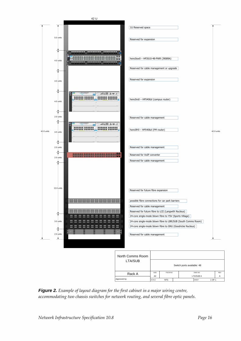
Major wiring centres may require one cabinet laid out in suitable form to accommodate
one or more chassis switches for network routing, as illustrated below.
Major wiring centres may require one cabinet reserved for Facilities Management
equipment including but not limited to AV equipment, CCTV equipment, Access
control equipment, etc. Allowance will be made for third-party equipment such as
CCTV equipment and cabinet space will be allocated by University of York IT Services
following receipt of space requirements from third parties.
Fibre panels shall be installed starting at the bottom of cabinets, leaving 2U (3.5”) at the
bottom of the cabinet for cable management.

Network Infrastructure Specification 10.8 Page 15
42.0 units
42 U
Sydney Smith Court
WCA1
LSM/A/0.??
Rack A
Approved by:
Switch ports available: 336
SIZE FSCM NO DWG NO REV
A4 LSM A (Bldg A) WC1 A A
SCALE NTS SHEET 1 OF 1
2.0 units
4.0 units
4.0 units
Reserved for Mediatrix VoIP converter
1.0 units
1 2 3 4 5 6 7 8 9 10 11 12 13 14 15 16 17 18 19 20 21 22 23 24
1 2 3 4 5 6 7 8 9 10 11 12 13 14 15 16 17 18 19 20 21 22 23 24
ProCurve
Power
Fault
Locator
Console22
21
24
23
20181614
19171513
121086
11975
42
31 ModeLinkModeLink ModeLink
Mode ModeLink Link
Mode
Mode Mode
ModeLink
Link
Link Link
Off = 10Mbps, Flash = 100Mbps, On = 1000Mbps*
Link Mode
Use only ProCurve mini-GBICs and SFPs
Gig
-T P
orts
SF
P P
orts
Spd Mode: 49
37
3836343230
35333129
2826
2725
46
45
48
47
444240
434139
50
5251
Reset Clear
LEDMode
Test
Status
FDx
Act
*PoE
Spd
RPS
PoE
EPS
Fan
All RJ-45 ports (1 - 50) are Auto-MDIXPoE-Integrated 10/100Base-TX Ports (1-48)ProCurve Switch
2610-48-PWR
J9089A
Reserved for future expansion
2.0 units
lsma1sw1 – HP2610-48-PWR (J9089A)
42.0 units
Reserved for cable management
Reserved for cable management or upgrade
24-core single-mode blown fibre from previous wiring centre
3.0 units 24-core single-mode blown fibre to next wiring centre)
Reserved for cable management or upgrade
4.0 units
1 2 3 4 5 6 7 8 9 10 11 12 13 14 15 16 17 18 19 20 21 22 23 24
1 2 3 4 5 6 7 8 9 10 11 12 13 14 15 16 17 18 19 20 21 22 23 24
ProCurve
Power
Fault
Locator
Console22
21
24
23
20181614
19171513
121086
11975
42
31 ModeLinkModeLink ModeLink
Mode ModeLink Link
Mode
Mode Mode
ModeLink
Link
Link Link
Off = 10Mbps, Flash = 100Mbps, On = 1000Mbps*
Link Mode
Use only ProCurve mini-GBICs and SFPs
Gig
-T P
orts
SF
P P
orts
Spd Mode: 49
37
3836343230
35333129
2826
2725
46
45
48
47
444240
434139
50
5251
Reset Clear
LEDMode
Test
Status
FDx
Act
*PoE
Spd
RPS
PoE
EPS
Fan
All RJ-45 ports (1 - 50) are Auto-MDIXPoE-Integrated 10/100Base-TX Ports (1-48)ProCurve Switch
2610-48-PWR
J9089A
lsma1sw0 – HP2610-48-PWR (J9089A)
Reserved for cable management or upgrade
4.0 units
1 2 3 4 5 6 7 8 9 10 11 12 13 14 15 16 17 18 19 20 21 22 23 24
1 2 3 4 5 6 7 8 9 10 11 12 13 14 15 16 17 18 19 20 21 22 23 24
ProCurve
Power
Fault
Locator
Console22
21
24
23
20181614
19171513
121086
11975
42
31 ModeLinkModeLink ModeLink
Mode ModeLink Link
Mode
Mode Mode
ModeLink
Link
Link Link
Off = 10Mbps, Flash = 100Mbps, On = 1000Mbps*
Link Mode
Use only ProCurve mini-GBICs and SFPs
Gig
-T P
orts
SF
P P
orts
Spd Mode: 49
37
3836343230
35333129
2826
2725
46
45
48
47
444240
434139
50
5251
Reset Clear
LEDMode
Test
Status
FDx
Act
*PoE
Spd
RPS
PoE
EPS
Fan
All RJ-45 ports (1 - 50) are Auto-MDIXPoE-Integrated 10/100Base-TX Ports (1-48)ProCurve Switch
2610-48-PWR
J9089A
lsma1sw2 – HP2610-48-PWR (J9089A)
Reserved for cable management or upgrade
4.0 units
1 2 3 4 5 6 7 8 9 10 11 12 13 14 15 16 17 18 19 20 21 22 23 24
1 2 3 4 5 6 7 8 9 10 11 12 13 14 15 16 17 18 19 20 21 22 23 24
ProCurve
Power
Fault
Locator
Console22
21
24
23
20181614
19171513
121086
11975
42
31 ModeLinkModeLink ModeLink
Mode ModeLink Link
Mode
Mode Mode
ModeLink
Link
Link Link
Off = 10Mbps, Flash = 100Mbps, On = 1000Mbps*
Link Mode
Use only ProCurve mini-GBICs and SFPs
Gig
-T P
orts
SF
P P
orts
Spd Mode: 49
37
3836343230
35333129
2826
2725
46
45
48
47
444240
434139
50
5251
Reset Clear
LEDMode
Test
Status
FDx
Act
*PoE
Spd
RPS
PoE
EPS
Fan
All RJ-45 ports (1 - 50) are Auto-MDIXPoE-Integrated 10/100Base-TX Ports (1-48)ProCurve Switch
2610-48-PWR
J9089A
lsma1sw3 – HP2610-48-PWR (J9089A)
Reserved for cable management or upgrade
4.0 units
1 2 3 4 5 6 7 8 9 10 11 12 13 14 15 16 17 18 19 20 21 22 23 24
1 2 3 4 5 6 7 8 9 10 11 12 13 14 15 16 17 18 19 20 21 22 23 24
ProCurve
Power
Fault
Locator
Console22
21
24
23
20181614
19171513
121086
11975
42
31 ModeLinkModeLink ModeLink
Mode ModeLink Link
Mode
Mode Mode
ModeLink
Link
Link Link
Off = 10Mbps, Flash = 100Mbps, On = 1000Mbps*
Link Mode
Use only ProCurve mini-GBICs and SFPs
Gig
-T P
orts
SF
P P
orts
Spd Mode: 49
37
3836343230
35333129
2826
2725
46
45
48
47
444240
434139
50
5251
Reset Clear
LEDMode
Test
Status
FDx
Act
*PoE
Spd
RPS
PoE
EPS
Fan
All RJ-45 ports (1 - 50) are Auto-MDIXPoE-Integrated 10/100Base-TX Ports (1-48)ProCurve Switch
2610-48-PWR
J9089A
lsma1sw4 – HP2610-48-PWR (J9089A)
Reserved for cable management or upgrade
4.0 units
1 2 3 4 5 6 7 8 9 10 11 12 13 14 15 16 17 18 19 20 21 22 23 24
1 2 3 4 5 6 7 8 9 10 11 12 13 14 15 16 17 18 19 20 21 22 23 24
ProCurve
Power
Fault
Locator
Console22
21
24
23
20181614
19171513
121086
11975
42
31 ModeLinkModeLink ModeLink
Mode ModeLink Link
Mode
Mode Mode
ModeLink
Link
Link Link
Off = 10Mbps, Flash = 100Mbps, On = 1000Mbps*
Link Mode
Use only ProCurve mini-GBICs and SFPs
Gig
-T P
orts
SF
P P
orts
Spd Mode: 49
37
3836343230
35333129
2826
2725
46
45
48
47
444240
434139
50
5251
Reset Clear
LEDMode
Test
Status
FDx
Act
*PoE
Spd
RPS
PoE
EPS
Fan
All RJ-45 ports (1 - 50) are Auto-MDIXPoE-Integrated 10/100Base-TX Ports (1-48)ProCurve Switch
2610-48-PWR
J9089A
lsma1sw5 – HP2610-48-PWR (J9089A)
Reserved for cable management or upgrade
1 2 3 4 5 6 7 8 9 10 11 12 13 14 15 16 17 18 19 20 21 22 23 24
1 2 3 4 5 6 7 8 9 10 11 12 13 14 15 16 17 18 19 20 21 22 23 24
ProCurve
Power
Fault
Locator
Console22
21
24
23
20181614
19171513
121086
11975
42
31 ModeLinkModeLink ModeLink
Mode ModeLink Link
Mode
Mode Mode
ModeLink
Link
Link Link
Off = 10Mbps, Flash = 100Mbps, On = 1000Mbps*
Link Mode
Use only ProCurve mini-GBICs and SFPs
Gig
-T P
orts
SF
P P
orts
Spd Mode: 49
37
3836343230
35333129
2826
2725
46
45
48
47
444240
434139
50
5251
Reset Clear
LEDMode
Test
Status
FDx
Act
*PoE
Spd
RPS
PoE
EPS
Fan
All RJ-45 ports (1 - 50) are Auto-MDIXPoE-Integrated 10/100Base-TX Ports (1-48)ProCurve Switch
2610-48-PWR
J9089A
lsma1sw6 – HP2610-48-PWR (J9089A)
20-pair telephony multicore on 25-way panel
4.0 units
Reserved for cable management
2.0 units Reserved for future fibre expansion
Reserved for cable management
Figure 1. Example of standard cabinet layout diagram, accommodating 14 patch panels
and up to 336 data outlets; space has been left for one more set.
Network Infrastructure Specification 10.8 Page 16
42.0 units
42 U
North Comms Room
LTA/SUB
Rack A
Approved by:
Switch ports available: 48
SIZE FSCM NO DWG NO REV
A4 LTA/SUB A A
SCALE NTS SHEET 1 OF 1
2.0 units
Power
Fault
Locator
E F
C D
A
ProCurve NetworkingHP Innovation
zlProCurve
24p Gig-T
zl Module
J8702A PoE-Integrated 10/100/1000Base-T Ports (1-24) - Ports are IEEE Auto MDI/MDI-X
1 5
62
3
4
7 11
128
9
10
13 17
1814
15
16
19 23
2420
21
22 zlProCurve
24p Gig-T
zl Module
J8702A PoE-Integrated 10/100/1000Base-T Ports (1-24) - Ports are IEEE Auto MDI/MDI-X
1 5
62
3
4
7 11
128
9
10
13 17
1814
15
16
19 23
2420
21
22
ConsoleReset Clear
Auxiliary Port
ProCurve Switch 5400zl
Management Module
J8726A
Internal
PowerPoE
Pwr
2
1
2
4
1
3
PoE
Temp
Fan
Flash
DIMM
Mgmt
ChasTest
LED ModeModules
Status
Act
FDx
Spd Usr
PoE
H
J
LK
I
G
F
D
B
E
C
A
ProCurve
Switch 5406zl
J8699A PoE
Use
zl Modules
only
B
4.0 units
10.0 units
Reserved for VoIP converter
4.0 units
5.0 units
henc0fr0 – HP5406zl (FM router)
1 2 3 4 5 6 7 8 9 10 11 12 13 14 15 16 17 18 19 20 21 22 23 24
1 2 3 4 5 6 7 8 9 10 11 12 13 14 15 16 17 18 19 20 21 22 23 24
ProCurve
Power
Fault
Locator
Console22
21
24
23
20181614
19171513
121086
11975
42
31 ModeLinkModeLink ModeLink
Mode ModeLink Link
Mode
Mode Mode
ModeLink
Link
Link Link
Off = 10Mbps, Flash = 100Mbps, On = 1000Mbps*
Link Mode
Use only ProCurve mini-GBICs and SFPs
Gig
-T P
orts
SF
P P
orts
Spd Mode: 49
37
3836343230
35333129
2826
2725
46
45
48
47
444240
434139
50
5251
Reset Clear
LEDMode
Test
Status
FDx
Act
*PoE
Spd
RPS
PoE
EPS
Fan
All RJ-45 ports (1 - 50) are Auto-MDIXPoE-Integrated 10/100Base-TX Ports (1-48)ProCurve Switch
2610-48-PWR
J9089A
2.0 units
Reserved for future fibre expansion
2.0 units
henc0sw0 – HP2610-48-PWR (J9089A)
42.0 units
Reserved for cable management
4.0 units
1U Reserved space
Reserved for cable management
Reserved for cable management2.0 units
4.0 unitsReserved for expansion
Reserved for cable management
24-core single-mode blown fibre to GNU (Goodricke Nucleus)
Power
Fault
Locator
E F
C D
A
ProCurve NetworkingHP Innovation
zlProCurve
24p Gig-T
zl Module
J8702A PoE-Integrated 10/100/1000Base-T Ports (1-24) - Ports are IEEE Auto MDI/MDI-X
1 5
62
3
4
7 11
128
9
10
13 17
1814
15
16
19 23
2420
21
22 zlProCurve
24p Gig-T
zl Module
J8702A PoE-Integrated 10/100/1000Base-T Ports (1-24) - Ports are IEEE Auto MDI/MDI-X
1 5
62
3
4
7 11
128
9
10
13 17
1814
15
16
19 23
2420
21
22
ConsoleReset Clear
Auxiliary Port
ProCurve Switch 5400zl
Management Module
J8726A
Internal
PowerPoE
Pwr
2
1
2
4
1
3
PoE
Temp
Fan
Flash
DIMM
Mgmt
ChasTest
LED ModeModules
Status
Act
FDx
Spd Usr
PoE
H
J
LK
I
G
F
D
B
E
C
A
ProCurve
Switch 5406zl
J8699A PoE
Use
zl Modules
only
B
henc0rs0 – HP5406zl (campus router)
3.0 units
24-core single-mode blown fibre to YSV (Sports Village)
24-core single-mode blown fibre to LBR/SUB (South Comms Room)
Reserved for cable management or upgrade
Reserved for expansion
possible fibre connections for car park barriers
Reserved for future fibre to LCE (Langwith Nucleus)
Reserved for cable management
Figure 2. Example of layout diagram for the first cabinet in a major wiring centre,
accommodating two chassis switches for network routing, and several fibre optic panels.

Network Infrastructure Specification 10.8 Page 17
42.0 units
42 U
JB Morrell Library
WC0
(Room LMO/0.05)
Rack B
Approved by:
FM equipment and fibre connections
Edge switch ports available: 0
SIZE FSCM NO DWG NO REV
A4 LMO-WC0-B A
SCALE NTS SHEET 1 OF 1
5.0 units
3.0 units
2.0 units
lmo0rf0 – HP5304xl
4.0 units
2.0 units
42.0 units
Reserved for cable management
Reserved space
Reserved for future expansion
Reserved for resilient fibres to ITS and BSDC
16.0 units
Reserved for cable management
10.0 units
1.0 units
Console
BA
C D
Power
Fault
Self
Test
Fan
Fault
Reset ClearLED Mode Select
1 2 A B C D
Power
Status
Modules
Act FDx Max
hp procurve
switch 5304xl
J4850A use xl modules only
xlhp procurve
mini-GBIC
xl Module
J4878B
J4878B 4 port mini-GBIC
1
1
2
2
3
3
4
4
mini-GBIC Ports
J4859C
1000 LX-LC
J4859C
1000 LX-LC
J4859C
1000 LX-LC
xlhp procurve
100/1000TX
xl Module
J4907A8
J4907A 16 port Gig-T/GBIC
7
14
6
13
5
12
4
11
3
10
2
9
1
81
14
715 16T MMT
xlhp procurve
mini-GBIC
xl Module
J4878B
J4878B 4 port mini-GBIC
1
1
2
2
3
3
4
4
mini-GBIC Ports
xlhp procurve
mini-GBIC
xl Module
J4878B
J4878B 4 port mini-GBIC
1
1
2
2
3
3
4
4
mini-GBIC Ports
J4859C
1000 LX-LC
J4859C
1000 LX-LC
AMG Vison
System 2000
12-core MM first floor
CCTV analogue video chassis
24-core Security fibre
24-core MM RBL
12-core OM2 IT Services
12-core MM second floor
Indigo
Vision Indigo Vision CCTV chassis
Reserved for 5406 FM router
Power
Fault
Locator
E F
C D
A
ProCurve NetworkingHP Innovation
zlProCurve
24p Gig-T
zl Module
J8702A PoE-Integrated 10/100/1000Base-T Ports (1-24) - Ports are IEEE Auto MDI/MDI-X
1 5
62
3
4
7 11
128
9
10
13 17
1814
15
16
19 23
2420
21
22 zlProCurve
24p Gig-T
zl Module
J8702A PoE-Integrated 10/100/1000Base-T Ports (1-24) - Ports are IEEE Auto MDI/MDI-X
1 5
62
3
4
7 11
128
9
10
13 17
1814
15
16
19 23
2420
21
22
ConsoleReset Clear
Auxiliary Port
ProCurve Switch 5400zl
Management Module
J8726A
Internal
PowerPoE
Pwr
2
1
2
4
1
3
PoE
Temp
Fan
Flash
DIMM
Mgmt
ChasTest
LED ModeModules
Status
Act
FDx
Spd Usr
PoE
H
J
LK
I
G
F
D
B
E
C
A
ProCurve
Switch 5406zl
J8699A PoE
Use
zl Modules
only
B
1.0 units
2.0 units
Reserved for cable management
Reserved for cable management
8.0 units
Reserved for cable management
14.0 units
Figure 3. Example of layout diagram for a “Facilities Management” cabinet in a major wiring
centre, accommodating third-party equipment and associated fibre optic panels.

Network Infrastructure Specification 10.8 Page 18
5.3 Installation
Wiring centres, including the exterior and interior of data cabinets, shall be cleaned and
free of dust and debris before installation of any active equipment.
Patch panels and other equipment shall be fitted using M6 pan-head Pozidrive screws
only, secured to M6 cage nuts.
All equipment shall be aligned vertically on 1U boundaries.
By prior agreement with University of York IT Services only, equipment which is not
inherently rack-mounting may be installed on a fixed shelf which shall be aligned on a
1U boundary.
Within cabinets, cable bundles shall
be enclosed in cable socks up to the
point at which the bundles are split
out in to individual cables, and shall
be affixed to cable trays with Velcro
or equivalent non-crushing cable
ties.
Sufficient slack shall be left in cable
bundles to allow minor
repositioning of panels, to at least 1U
up or down.
Cables in cabinets shall be suitably
dressed such that there is clear space
for unimpeded installation of active
equipment to the full depth of the
cabinet between any two adjacent
patch panels.
In multi-storey buildings, outlet
terminations for each floor or
equivalent aggregated area shall be
made on its own group or groups of
panels, and wherever practical in its
own data cabinet.
Figure 4. Cabinet layout after patching with 0.25m
patch leads, showing groups of two 1U 24-port
Cat.6A patch panels, located above and below a 48
port PoE switch. Note gaps left to facilitate
maintenance and airflow. Note also the dressing of
the cables to facilitate the switch installation.
Network Infrastructure Specification 10.8 Page 19
When additional outlets are installed from any wiring centre, unused sections of patch
panels shall be utilised before adding additional patch panels.
Data patch panels must be high-density i.e. 24 sockets per 1U height.
Each patch panel must be earthed to the manufacturer’s specifications.
Data outlets, RJ45 patch panels and fibre optic patch panels shall be labelled in
accordance with Section 6.
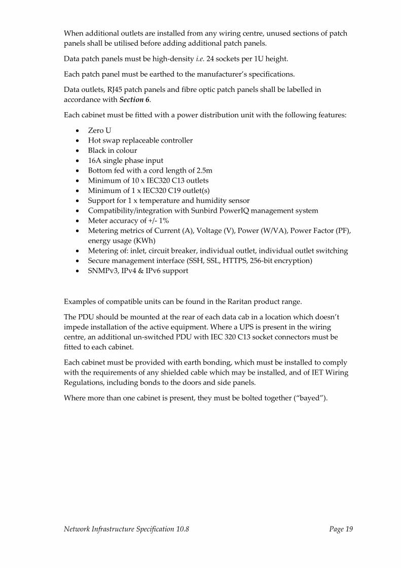
Each cabinet must be fitted with a power distribution unit with the following features:
Zero U
Hot swap replaceable controller
Black in colour
16A single phase input
Bottom fed with a cord length of 2.5m
Minimum of 10 x IEC320 C13 outlets
Minimum of 1 x IEC320 C19 outlet(s)
Support for 1 x temperature and humidity sensor
Compatibility/integration with Sunbird PowerIQ management system
Meter accuracy of +/- 1%
Metering metrics of Current (A), Voltage (V), Power (W/VA), Power Factor (PF),
energy usage (KWh)
Metering of: inlet, circuit breaker, individual outlet, individual outlet switching
Secure management interface (SSH, SSL, HTTPS, 256-bit encryption)
SNMPv3, IPv4 & IPv6 support
Examples of compatible units can be found in the Raritan product range.
The PDU should be mounted at the rear of each data cab in a location which doesn’t
impede installation of the active equipment. Where a UPS is present in the wiring
centre, an additional un-switched PDU with IEC 320 C13 socket connectors must be
fitted to each cabinet.
Each cabinet must be provided with earth bonding, which must be installed to comply
with the requirements of any shielded cable which may be installed, and of IET Wiring
Regulations, including bonds to the doors and side panels.
Where more than one cabinet is present, they must be bolted together (“bayed”).

Network Infrastructure Specification 10.8 Page 20
6. Labelling
6.1 External cabling
External fibre optic cables shall be labelled at each end and in each access chamber
using a suitably durable marker e.g. Critchley, Traffolyte or laser-etched perspex.
Cable markers should use the following convention:
Department code (University of York four digit code),
Space character,
Endpoint ID (two building codes up to 7 characters each, separated by a
hyphen),
Space character,
Sequence number (one digit)
Example 1:
The second of two IT Services cables running between Alcuin College D block and
Alcuin Teaching Block) will be labelled 0087 A/D-ATB 2
Example 2:
A single IT Services cable , running between Goodricke College Baker Court block
A2 and Goodricke College Sheldon Court Substation: 0087 GBA/A2-GSH/SUB 1
Commonly used departmental codes are:
0087 IT Services
0244 Telephony
0238 Estates and Campus Services
0246 Security Services
0006 Computer Science
Micro ducts shall be labelled at each end, in each access chamber and where they are
diverted or “tee’d” from the rest of the bundle, in the same style as fibre optic cables.
6.2 Fibre optic patch panels
Fibre optic panels shall be labelled with the number of cores, the type of cable (single
mode or multimode), and the source and destination. For example:
24-core single mode Alcuin WC1 to IT Services WC 1
6.3 Data outlets
Rooms and other spaces must be allocated their final space codes before labelling data
outlets or patch panels. Outlets and patch panels shall not be labelled with interim
numbers which may be indicated on, for example, architect’s plans prior to completion
of building works.
By convention the University of York numbers rooms with three digits, of which the
first is the floor number. For example, room A/D/131 is located on the first floor of
Alcuin College D block. All building codes and space codes will be supplied by the
University.
Network Infrastructure Specification 10.8 Page 21
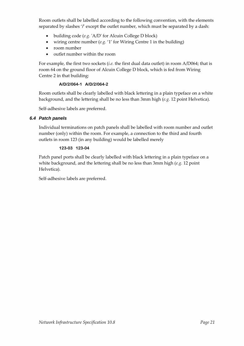
Room outlets shall be labelled according to the following convention, with the elements
separated by slashes ‘/’ except the outlet number, which must be separated by a dash:
building code (e.g. 'A/D' for Alcuin College D block)
wiring centre number (e.g. ‘1’ for Wiring Centre 1 in the building)
room number
outlet number within the room
For example, the first two sockets (i.e. the first dual data outlet) in room A/D064; that is
room 64 on the ground floor of Alcuin College D block, which is fed from Wiring
Centre 2 in that building:
A/D/2/064-1 A/D/2/064-2
Room outlets shall be clearly labelled with black lettering in a plain typeface on a white
background, and the lettering shall be no less than 3mm high (e.g. 12 point Helvetica).
Self-adhesive labels are preferred.
6.4 Patch panels
Individual terminations on patch panels shall be labelled with room number and outlet
number (only) within the room. For example, a connection to the third and fourth
outlets in room 123 (in any building) would be labelled merely
123-03 123-04
Patch panel ports shall be clearly labelled with black lettering in a plain typeface on a
white background, and the lettering shall be no less than 3mm high (e.g. 12 point
Helvetica).
Self-adhesive labels are preferred.

Network Infrastructure Specification 10.8 Page 22
7. Acceptance testing and documentation
7.1 Structured cabling
University of York IT Services will not patch or “make live” data outlets until they are
in receipt of the necessary documentation described here.
All data cable related work, including cable installation, re-installation, rework,
modification, or movement of data outlets, trunking or containment replacement, and
any other work that involves adding, repairing or moving outlets or their cabling shall
be tested and (re)certified according to the approved regime and standards.
Acceptance of data cabling and associated infrastructure by University of York IT
Services is conditional on receipt of as-fitted drawings showing positions of the dual
data outlets with correct outlet labelling, schedules of panel connections, and valid test
results.
All wiring installations shall be tested to ensure conformity with Category 6A (or 5e
where applicable), BS EN 50173 or IEC 11801, or better. Note that European standards
are revised from time to time and adoption of the latest standards will normally be
expected.
Test results shall be delivered in electronic form as Fluke Linkware files or Ideal
DataCenter showing the complete test results to Cat.6A or Cat.5e standards as
appropriate, for each outlet.
As-fitted drawings shall be delivered in electronic format as PDF and DWG documents
and shall be of sufficient resolution to read data outlet designations when printed at A3
size. They shall consist of one or more A3 pages per floor, if necessary with floors split
over multiple pages with an overlap to allow for recombination.
All wiring installations must be supported by a manufacturer’s Performance Warranty
or equivalent, valid for a minimum of 20 years. Documentary evidence in the form of
the manufacturer’s certificate for the specific installation must be provided in support
of this.
7.2 Fibre optic installations
Fibre optics shall be terminated in pairs on LC duplex connectors fitted to patch panels
in accordance with Section 2.3. The fibre optic cables shall be labelled in accordance
with Section 6.1 and the panels shall be labelled in accordance with Section 6.2.
Each pair in a fibre optic installation shall be fitted as a crossover. Because fibre optic
connections require overall Tx-to-Rx crossover connections, this is essential in order to
preserve an odd number of Tx-to-Rx crossovers when patching.
All fibre installations shall be tested to produce measurements of both ILM (Insertion
Loss Measurement) and OTDR (Optical Time Domain Reflectometry). ILM tests shall be
conducted from both ends. The test results shall be provided to IT Services in electronic
form, either as EXFO files or Fluke Linkware files.
Acceptance of fibre optic cabling and associated infrastructure by University of York IT
Services is conditional on correct outlet labelling and receipt of valid test results.
Network Infrastructure Specification 10.8 Page 23
8. Connected equipment
8.1 Registration
Unless otherwise directed by University of York IT Services Network Operations staff,
equipment shall not be connected to any part of the University network until it has been
properly registered in the LAN database, an IP address and a hostname has been
allocated, and the relevant part of the “Facilities Network” has been made accessible.
Requests for allocation of IP addresses for “Facilities Management” type devices such as
BMS, CCTV, EPoS, Access Control, emergency lighting, alarm systems, and other
equipment can be made via the “Moves & Changes” web-based system or by raising a
call with the IT Service Desk see Section 11.
Only the contractor actually installing the equipment may request device registration.
Note that it may take several days to satisfy IP address requests, especially where the
secured parts of the “Facilities Network” have to be created specially.
Equipment shall be labelled with the hostname allocated by University of York IT
Services, and this name must be included in any communication with University of
York IT Services.
If any equipment is relocated or replaced, University of York IT Services must be
informed of the change of location or MAC address and the new or relocated
equipment shall not be (re)connected until authorised. In some cases this may require
allocation of a different hostname.
8.2 Prohibitions
All standard active network equipment (routers, switches and WiFi access points) shall
be funded by the construction/refurbishment project but specified and/or provided by
the University of York IT Services. Other, specialist equipment that include an element
of networking may be provided by contractors but can only be connected to the
network through consultation with University of York IT Services.
No local or private network switches or wireless devices are permitted on the
University network. All devices must be connected directly to University network
outlets.
No other equipment operating in the 2.4GHz or 5GHz bands is permitted on the
University campus, except for certain very-low-power devices operating at 2.4GHz
with the written permission of University of York IT Services.
All other network-connected equipment shall be installed by the relevant contractor, in
compliance with safety and positioning requirements advised by University of York IT
Services, and shall be connected directly to a data outlet.

Network Infrastructure Specification 10.8 Page 24
9. Approved manufacturers and cabling systems
9.1 Augmented Category 6 (Cat.6A) infrastructure
Solutions are welcomed from the following manufacturers:
Brand Rex Cat 6A. U/FTP
Brand Rex Cat 6A. F/FTP
Hellerman Tyton unshielded Cat 6A
Hellerman Tyton shielded Cat 6A
Nexans shielded LANmark 6A F1/UTP
Nexans shielded LANmark 6A F/FTP
9.2 Enhanced Category 5 (Cat.5e) infrastructure
Solutions are welcomed from the following manufacturers:
Brand Rex Cat 5e
Hellerman Tyton cat 5e
Nexans LANmark 5
9.3 Blown fibre components
Blown fibre solutions are welcomed from the following manufacturers:
Brand Rex
Emtelle
TFK
Nexans

Network Infrastructure Specification 10.8 Page 25
10. Compliance
10.1 Legislative compliance
All solutions must comply with current legislation in particular, but not limited to, Part
M Building Regulations 2013 specifically, ‘Access to and use of buildings’.
10.2 Estates requirements
All contractors must comply with University of York contractor competency
requirements. Please see ‘Contractor Competency Check List’ on the following web
page:
https://www.york.ac.uk/admin/estates/operations/business/helpdesk/Contractorinfo.ht
ml
(N.B. – University control may not be necessary if operating in a CDM or “closed” site).
10.3 Technical compliance
All structured cabling systems and their installation must comply with the following
standard as applicable:
BS EN 50173
BS EN 50174
BS EN 50310
BS EN 50346
IEC/ISO 11801
BS6701
BS7671
10.4 Approved installers
For reasons of warranty, all installations must be undertaken by a contractor that is a
manufacturer approved installer for the system being installed (see Section 9).

Network Infrastructure Specification 10.8 Page 26
11. Document updates, website references and IT Service Desk details
11.1 General requirements
This document will be updated periodically. Anybody using this document especially
contractors and Project Managers should ensure they are working to the latest version
by visiting:
http://www.york.ac.uk/it-services/info/contractors/
11.2 Useful websites
To request device registration and obtain IP addressing details please visit:
http://www.york.ac.uk/it-services/facilities/moves/
Or
contact the IT Service Desk (See Section 11.3)
11.3 IT Service Desk details
To contact the It Service Desk to request a device registration or raise a general enquiry
please ring 01904 323838 or e-mail: [email protected] or visit:
http://www.york.ac.uk/it-services/

Network Infrastructure Specification 10.8 Page 27
12. University of York staff
Job title Post holder Responsible for Contact details
Head of
Networking
Mr J R
Mason
Strategic planning; University
committee representation; IT
Services budgets; network
architecture and design;
procurement
Email:
Tel: 01904 323813
Network
Operations
Manager
Mrs E
Coultish
Network operations; installation
and commissioning;
procurement; IP Telephony;
wireless networking; contractor
and Estates Services liaison
Email:
Tel: 01904 328467
IT Infrastructure
Projects Manager
Mr G
Borwell
Project management; contractor
and Estates Services liaison
Email:
Tel: 01904 323888
Network
Technician
Mr D
Munday
Installation and commissioning;
contractor and Estates Services
liaison
Email:
Tel: 01904 328469
Data Centre
Manager
Mr S
Wielgosz
Data Centre operations and
development
Email:
Tel: 01904 323826