GENERAL INFRASTRUCTURE SPECIFICATION
127
GENERAL INFRASTRUCTURE SPECIFICATION (Based on Relevant Australian Standards &Vic Roads Specifications) August 2012 © Note: Contract specifications as provided on approved drawings shall take precedence, unless stated otherwise
Transcript of GENERAL INFRASTRUCTURE SPECIFICATION

GENERAL INFRASTRUCTURE SPECIFICATION (Based on Relevant Australian Standards &Vic Roads Specifications)
August 2012 © Note: Contract specifications as provided on approved drawings shall take precedence, unless stated otherwise

HRCC INFRASTRUCTURE SPECIFICATION
Page 2 of 127

HRCC INFRASTRUCTURE SPECIFICATION
Page 3 of 127
Revision History
Date Version Name Reason
05/08/2012 1.0 Priyan Wijeyeratne HRCC Specification
31/01/2014 1.1 Ram Upadhyaya & Priyan Wijeyeratne
HRCC Specification
25/02/2014 1.2 Priyan Wijeyeratne Up dated
28/08/2017 1.3 Lyndon White E39 INSPECTION OF DRAINAGE LINES added
Approval History
Date Name and title Signature
05/08/2012 Priyan Wijeyeratne PW
31/01/2014 Priyan Wijeyeratne PW
25/02/2014 Priyan Wijeyeratne PW
28/08/2017 Lyndon White LW

HRCC INFRASTRUCTURE SPECIFICATION
Page 4 of 127
CONTENTS
PART A - GENERAL PROVISIONS ...................................................................................................................... 5
PART B – EARTHWORKS & ROAD PAVEMENT .............................................................................................. 11
PART D - KERB AND CHANNEL ........................................................................................................................ 35
PART E - CULVERTS AND DRAINS .................................................................................................................... 40
PART F - FOOTPATHS .......................................................................................................................................... 53
PART G - REINSTATEMENT OF NATURESTRIPS ........................................................................................... 61
PART H - SPRAY SEALS ...................................................................................................................................... 62
PART I – ASPHALT ................................................................................................................................................ 74
PART J - SIGNAGE ................................................................................................................................................ 93
PART K - PAVEMENT MARKINGS AND DELINEATION .................................................................................. 98
PART L - MINOR BRIDGES AND CULVERTS ................................................................................................. 112
Note: In general HRCC supply & install all signage & pavement marking required throughout the municipality, unless decided otherwise.
Testing of material & works must be as per the specification and as directed by the Superintendent. The contractor shall bear the cost of testing and reporting.
Hold-points and milestones must be followed as per the Contract and/or as discussed and agreed by all parties
prior to commencement of workS.
Contractor must sign a statutory declaration before final payment is made by the HRCC that it has paid all its suppliers and sub-contractors and there are no outstanding payments to them.

HRCC INFRASTRUCTURE SPECIFICATION
Page 5 of 127
PART A - GENERAL PROVISIONS
A1. EXTENT OF CONTRACT
The whole of the works to be carried out under the Contract shall conform to the requirements of this specification, the accompanying Plans and Drawings, and General Conditions of Contract AS 2124: , and shall be carried out under the direction and to the satisfaction of the Superintendent of HRCC’s Technical Services Department or his representative.
A2. COPIES OF PLANS AND SPECIFICATIONS
These Plans and Specifications are the property of the Council. Copies of the Plans and Specifications will be supplied to tenderers without payment of a deposit, but shall remain a property of HRCC.
A3. QUANTITIES
The quantities attached to this specification and shown on the Plans have been taken out with care, and are furnished only for the guidance of tenderers. They are not guaranteed by the Council and form no part of the specification.
A4. NATURE OF GROUND
The Contractor shall be responsible for satisfying himself as to the nature and extent of the specified works and the physical and legal conditions under which the works will be carried out, including the means of access, extent of clearing, nature of the ground, including subsoil, rocks, boulders, roots, dead timber, etc., type of mechanical plant required, location and suitability of water supply for construction and testing purposes and any other like matters affecting the construction of the works, as no claims for extras on account of these will afterwards be admitted; the prices stated on the Schedule being held to include all risks incidental to, and works required for the performance of this Contract.
A5. DRAWINGS
The works covered by this Specification shall be in accordance with the following plans and drawings:
Drawing Title Drawing No:
HRCC
HRCC
HRCC
HRCC
IDM
VicRoads
A6. SETTING OUT WORKS
The Superintendent shall provide the Contractor with level and alignment details necessary for the setting out of the works. The Contractor shall, at his own expense, set out adequately according to the Drawings and Specifications all the work comprised in this contract, and any variation thereof; and the Contractor shall be solely responsible for this work being set out and executed. The Contractor shall be responsible for the preservation and maintenance in their true position of all pegs put in, or reference marks fixed by the Superintendent or his representative in accordance with the provisions of this clause and he shall check all such pegs to satisfy himself as to their accuracy. In event of these pegs or reference marks being disturbed or obliterated the Contractor shall immediately notify the Superintendent who shall arrange for their replacement at the Contractor’s expense.
A7. CONTRACT SECURITY DEPOSIT
The successful tenderer shall lodge a security deposit to the amount of 5% of the Tender, which must be lodged after the contract is accepted and before works are commenced as a guarantee of performance. Council will hold this deposit as performance security for the due compliance with conditions of contract. This sum will be forfeited by the Council as damages for such failure to comply. Council may also retain this security deposit in lieu of retention moneys over the defects liability period.

HRCC INFRASTRUCTURE SPECIFICATION
Page 6 of 127
The principal also reserves the right to make deductions equal to the amount of the required security, if the deposit is not lodged as required by the Contract. Retention/security monies shall not bear any interest on balance for the duration held.
A8. INSURANCES
Insurance responsibilities are in accordance with the General Conditions of Contract AS 2124 1992 as determined in Annexure A of AS 2124 General Conditions of Contract.
A9. RISE AND FALL
This Contract is not subject to adjustment to compensate for rise and fall of costs.
A10. STANDARDS
The minimum requirement for methods, workmanship and materials used in the Contract are those Standards and Codes of Practice laid down in publications of the Standards Association of Australia, Vic Roads and Infrastructure Design Manual (IDM). When any Standard provides for witnessed tests and/or certificates of compliance of a material with the specification, the Contractor must assume that these are required and wanted by the Superintendent even though it may not be specifically stated hereinafter.
Where any Standard provides for varying grades or degrees of accuracy or tolerance, the Contractor must assume that the Superintendent expects the best grades, the maximum degree of accuracy and the minimum degrees of tolerance. Where any standard provides for additional tests, reports or evidence to be at the expense of the Principal, Council will have such tests carried out as it requires at its own expense. Wherever reference or inference is made to an Standard or Specification, the latest edition of each shall be used. Contract specifications & notes stated on approved construction drawings shall take precedence over these general Infrastructure specifications unless stated otherwise.
A11. OTHER CONTRACTORS
The Contractor shall, at all times, co-operate and co-ordinate with other Contractors and/or Service/Utility Authorities working in the area. i.e.: Roadworks, Water Supply, Gas and Fuel, Telstra, Powercor, etc. HRCC will not be liable for any losses to the Contractor for time delays due to utility authority works, except that the lost time (in days) will be added to the approved works program.
A12. TIME OF COMMENCEMENT
The Contractor shall commence the work of this Contract, as agreed and stipulated on the ‘Letter of Acceptance’.
A13. PAYMENTS
Claims for payment will be processed if received by the Superintendent one week prior to Council’s finance meetings.
A14. BY LAWS FEES AND NOTICES
The contractor shall comply with all By-Laws and Regulations of Local and Statutory Authorities having jurisdiction over the works and be responsible for the payment of all fees and customary charges and the giving and receiving of all necessary notices.
A15. PROGRAMME OF WORKS
(a) When so directed in the Letter of Acceptance or subsequently in writing by the Superintendent, the Contractor shall submit within 14 days of such direction, or within such other time as may be notified, a programme of works setting out in detail, and to any extent specified, his proposed order of works and his planned dates for completion of the various parts of the works, after taking into account all factors including supply of materials or works to be effected by the Council.
(b) If the Superintendent considers that the programme submitted does not show sufficient detail, or is impracticable, or will not result in completion of the whole of the Works by the Date for Practical Completion, he may direct the Contractor to amend the programme to his satisfaction within 7 days of a written notice to do so.

HRCC INFRASTRUCTURE SPECIFICATION
Page 7 of 127
(c) The Programme of Works submitted under part (a) hereof together with amendments under part (b) and any subsequent amen thereto submitted by the Contractor and accepted by the Superintendent, shall be termed the “Programme’ and shall become part of the Contract.
(d) Failure by the Contractor to submit within the time specified a programme which is acceptable to the Superintendent may be deemed by the Superintendent to be a breach of the Contract.
A16. REVIEW OF PROGRESS OF WORKS
At intervals not exceeding one month, the Contractor and the Superintendent, together, shall review the actual progress of the work in comparison with the programme.
A17. EXPLANATION OF DELAYS AND CONTRACTOR’S PROPOSALS FOR COMPLETION OF PROGRAMMED WORKS
At any time the Superintendent may require the Contractor to submit in writing within 14 days:
(i) an explanation of delays in execution of the works in comparison with the programme or any specified programme of works, together with any justifiable claims for extensions of time for completion of the works.
(ii) an amended works programme which is practicable and which is acceptable to the Superintendent.
Should the Contractor fail to do so the Superintendent may deem such failure to be a breach of the Contract.
A18. WORKS NOT PROGRAMMED
Where no programme is specified, and the Contractor has not been required to submit a programme under part (a) of Clause A15, the Contractor shall execute the works with diligence, dispatch and continuity. Should the Superintendent consider that the rate of progress is at any time too slow to ensure completion by the Date for Practical Completion he may direct the Contractor to submit within 14 days written details of his intended procedure for the execution of the balance of the works. Should the Contractor fail to do so, or should the Superintendent deem that such procedure is not practical or cannot result in completion of whole of the works by the date for Practical Completion, he may declare the Contractor’s failure to maintain a satisfactory rate of progress a breach of the Contract.
A19. ADVERSE WEATHER CONDITIONS
The Contractor’s tender will be deemed to include an allowance for any working time lost due directly or indirectly to adverse weather conditions that could reasonably be expected during the period of the Contract. Any claim for an extension of time due to the effect of unexpected adverse weather conditions shall be substantiated to the satisfaction of the Superintendent by relating records of the weather conditions prevailing at the work site during the period of the Contract to relevant historical information and by providing evidence that the progress of the work under the Contract was seriously affected by the unexpected adverse weather conditions and that all efforts to re-arrange the construction programme to minimize the effect of the unexpected adverse weather conditions were taken.
A20. INDUSTRIAL MATTERS
The Contractor shall keep the Superintendent informed concerning any industrial matter which could affect the progress of the work under the Contract. The Contractor shall inform the Superintendent immediately if bans are applied to the work under the Contract or if work under the Contract ceases due to industrial action, and shall also inform the Superintendent of measures being taken to resolve such action. Except as may be provided elsewhere in the Contract for adjustment for rise and fall in costs, the Contractor shall make no claim against the Council for increased labour costs, or for additional costs, loss or damage arising from increased labour costs, incurred by or as result of:
(a) any variation to any Award of the Australian Conciliation and Arbitration Commission or to any Award of the State Industrial Relations Commission, whether by consent or by formal arbitration;
(b) any agreement, award, settlement, fee or like payment made by the Contractor or any organization or any person acting on behalf of the Contractor with any union or any other body or any person;
(c) any industrial action through which occurs a strike, work stoppage, work ban or work limitation of any kind.

HRCC INFRASTRUCTURE SPECIFICATION
Page 8 of 127
Provided that any industrial action causing lost time does not arise from factors within the control of the Contractor, the Contractor may be granted an extension of time for completion pursuant to the General Conditions of Contract.
A21. NOTICE OF HOURS OF WORK
The Contractor shall give the Superintendent prior notice of the hours during which he intends to work; and unless written permission is given at least 24 hours in advance, the Contractor shall not work at night or during holidays or at weekends. It is the responsibility of the Contractor to arrange the completion of his Contract within the ordinary hours of work; but if work outside normal hours is agreed to in respect of some emergency, no claim for extra payment will be entertained and the Council may charge the Contractor for extra cost of supervision, if permission to work outside normal hours is denied then the Contractor will not be entitled to extra time to complete the Contract.
A22. CONTRACTOR’S REPRESENTATIVES
Before commencement of work the Contractor shall advise the Superintendent in writing of the names, addresses and telephone numbers of his representatives who can be contacted in any emergency which may require repairs to the work under the Contract or the replacement or maintenance of signs and devices. Any proposed changes of representatives, addresses or telephone numbers shall be notified promptly to the Superintendent and confirmed in writing to the Superintendent.
A23. ASSISTANCE TO THE SUPERINTENDENT
During the course of this Contract, the Contractor shall provide at his cost, such labour necessary to assist the Superintendent in carrying out testing, supervising, measuring, levelling, checking and examining, the works of the Contractor (This clause applies to all sections of this specification).
A24. SUBCONTRACTORS
Subcontractors may be employed by the Contractor subject to the Superintendent’s approval. The Contractor shall be responsible for all works, including that completed by Subcontractors.
A25. MATERIALS TO BE SUPPLIED BY CONTRACTOR
All materials required for satisfactory completion of the works shall be supplied by the Contractor.
A26. DELIVERY OF MATERIALS
All materials to be supplied by the Council will be available for collection by the contractor at the Council Depot, Selkirk Drive, Horsham. All items are to be loaded, transported, and unloaded by the Contractor, after inspection by the Superintendent.
A27. MEASURING INSTRUMENTS
The Contractor shall have available at the site of the works instruments including templates, straight edges, boning rods and spirit levels approved by the Superintendent for the measurement of length and the establishment and checking of lines and levels and cambers. These instruments shall be properly maintained and may be checked by the Superintendent at any time.
A28. PLANT, TOOLS AND MATERIALS
Unless otherwise specified the Contractor shall supply all plant, labour, tools, forms, templates, and materials necessary for the proper and full completion of the works.
A29. CONTRACTOR TO INFORM ITSELF OF MAINS & SERVICES
Prior to commencing any of the works of this contract, the Contractor shall obtain all relevant information from the appropriate authorities (Dial-before-you-dig) concerning the location of stormwater drains and any water, sewerage, electrical, telephone or gas mains or cables which may be affected by the works of this contract.
A30. ALTERATIONS TO SERVICES
Should any of these services require alterations due to the contract work, such alterations will be carried out by the Authority concerned. The Contractor will advise the Superintendent three days in advance of the day when the service or main is required to be altered and the Superintendent will arrange for the work to be carried out, free of charge to the Contractor.

HRCC INFRASTRUCTURE SPECIFICATION
Page 9 of 127
A31. DAMAGE TO SERVICES
The Contractor shall be responsible for any damage which, in the opinion of the Superintendent, has been caused to any of the above services by any works or operations under his control. The conditions contained in this clause shall extend for an indefinite period beyond the Defects Liability Period of the Contract.
A32. POLLUTION
The Contractor shall take all reasonable precaution to prevent pollution of any drain, dam or watercourse, and take steps to minimise the nuisance of dust, dirt and noise. Spillage of oil or fuel during servicing and fuelling operations shall be minimized and any harmful spillage shall be removed.
A33. SUPPRESSION OF DUST
The Contractor shall take measures necessary to keep airborne dust to a minimum. Such measures shall include the watering of stockpiles, haul roads and other work areas. Unless otherwise specified no separate payment will be made for the suppression of dust. If the Contractor fails to achieve adequate dust control, particularly where the safety and convenience of the public are affected, the Superintendent may take any action necessary and deduct the cost of such action from moneys due or becoming due to the Contractor. The Superintendent may direct the suspension of work at any time where that work in the Superintendent’s opinion creates a dust hazard or nuisance to the public, personnel working on the site or property such as crops, stock and houses in the vicinity of the work. Where the Superintendent has directed a suspension of work and considers that the Contractor could not have been expected to have adequately controlled the dust, the Superintendent may consider an extension of time pursuant to the General Conditions of Contract. No claim for increased costs due to such suspension will be considered.
A34. HEALTH AND WELFARE
The Contractor shall comply with all Regulations and Statutes associated with Health and Welfare, in relation to first aid facilities, sanitary facilities, canteens, changing rooms and protective clothing for employees. The Contractor shall produce his WorkCover Registration Number as required under Clause A8.
A35. SAFETY OF THE WORKS
Further to the Conditions of Contract, the Contractor shall be responsible for the implementation of safe site operations and methods of construction. The Contractor shall be responsible for ensuring that all employees are instructed concerning the hazards of the work under the Contract and that safe working practices are observed.
A36. SAFETY OF PERSONNEL
Further to the Conditions of Contract, the Contractor shall take necessary steps to ensure safe working conditions are maintained on the site. All relevant Regulations and recommendation, together with instructions given by the Superintendent shall be complied with at the Contractor’s expense. The Contractor shall notify the Superintendent of any accident or injury immediately.
A37. SAFETY OF THE PUBLIC
Further to Conditions of Contract, the Contractor shall ensure that the public are free of risks associated with excavations, working plant and obstructions, both during and outside of normal working hours. Plant must not be located in such a position as to cause any obstruction to, or be a danger to traffic. The Contractor, whilst engaged on the works of this Contract, shall bear in mind that he/she is acting on behalf of the Council and shall at all times be courteous when dealing with the public and the Contractor shall instruct his/her employees accordingly.
A38. CARE OF SITE
The Contractor shall keep the works site drained and clean and tidy as the works proceed and shall regularly remove from the site rubbish and surplus material arising from the execution of the works, or the performance of the maintenance requirements.

HRCC INFRASTRUCTURE SPECIFICATION
Page 10 of 127
Upon completion of the works, the Contractor shall in addition remove all buildings, workshops, temporary works and equipment which he may have been constructed or brought to the site for carrying out the works and shall remove any remaining rubbish or material and leave the site in a clean and tidy condition. At all times when his workmen are on site the Contractor shall render immediate assistance without charge to any person whose passage through the work zone may be obstructed or made difficult by or as a result of the Contractor’s operations. The Contractor shall be held responsible for any loss or damage arising from the neglect or insufficiency of precautions for the safety of traffic.
A39. PROVISION FOR TRAFFIC
The Contractor shall make provision for traffic, including pedestrians, in accordance with this section and the relevant parts of the Road Management Act 2004, Worksite Safety – Traffic Management Code of Practice, hereinafter referred to as the Code. The Contractor shall make such provision for traffic notwithstanding anything contained in the General Conditions of Contract. The number, type and location of signs and devices shall be not less than the standards set out in the Code as applicable and shall also meet the requirements of this section. Work shall not commence or continue at any location until all appropriate signs, devices and, traffic control are in place. At all times when the Contractor's employees are on site, the Contractor shall render immediate assistance without charge to any person whose lawful passage through a work area may be obstructed or made difficult by or as a result of the Contractor's operations. The Contractor must prepare a Traffic Management Plan in accordance with the Worksite Safety - Traffic Management Code of Practice and keep a copy of the plan onsite at all times. Signs must be erected in strict compliance with the Traffic Management Plan and must at all times after placement be kept clean, legible and placed using suitable stands that will withstand traffic and weather conditions likely to be encountered. The Contractor is responsible for conducting regular surveillance over the term of the contract to ensure that compliance with the Traffic Management Plan has been achieved at all times. Suitable records must be kept and made available to the Superintendent on demand.

HRCC INFRASTRUCTURE SPECIFICATION
Page 11 of 127
PART B – EARTHWORKS & ROAD PAVEMENT
EARTHWORKS
B1. DESCRIPTION
This part covers the forming and grading of earthworks including excavation, placement and compaction of filling, disposal of surplus and unsuitable materials, and the trimming of batters, surface drains and formations. The clauses contained in Part A, General Provisions, shall be read in conjunction with the clauses contained below in Part B, Earthworks and Pavement Construction.
B2. CONFORMITY WITH DRAWINGS
All earthworks shall be finished to conform to the lines and levels specified or shown on the drawings or as directed by the Superintendent. The levels for all earthworks shall be checked by the Superintendent during the course of the contract and as directed by the Superintendent.
B3. SETTING OUT WORKS
Survey pegs, level pegs, and bench marks shall not be covered or removed or otherwise disturbed without the authority of the Superintendent.
(a) The Contractor shall set out the work in accordance with the drawings.
(b) The alignment and level pegs will be checked and approved on the site by the Superintendent prior to the commencement of work. (See also Part A, General Provisions, Clause A6)
MATERIAL SUPPLY
B4. GENERAL
Unless otherwise specified, the Contractor shall make his own arrangements to obtain all materials required to satisfactorily complete the work specified. The requirements of Clauses B25 - B29 ”Procurement and Transport of Materials” shall be strictly observed.
B5. AUSTRALIAN STANDARDS
All materials supplied by the Contractor shall conform to the relevant Australian Standard or where no standard exists, shall be of a quality approved by the Superintendent.
B6. MATERIALS SOURCE
The Contractor shall inform the Superintendent of the source from where the various materials will be procured, supplied or of the places of their manufacture, and shall, at least two days in advance, submit samples of the material to the Superintendent for inspection and/or testing.
B7. SAMPLES AND TESTING
Adequate samples of each kind of material shall be submitted to the Superintendent and, when these samples are approved, the respective materials shall conform to them in every respect. Whenever directed by the Superintendent, samples of the required size, number and description shall be prepared by the Contractor and submitted to tests as specified or to such additional tests as may be required. If any of the samples so tested do not fully comply with the required standards, the materials from which the samples have been taken and all materials of similar manufacture and all articles made there from may be absolutely rejected, in which case they shall be replaced by the contractor with new and sound materials which shall be again submitted to test if required.
B8. NOTICES FOR MATERIALS
The Contractor shall give sufficient notice to the Superintendent or his representatives to enable any materials brought upon the site to be examined and all materials shall be stacked as directed to facilitate this examination. All materials, that in the opinion of the Superintendent are unsuitable for the work shall be immediately removed from the site and in the event of the Contractor refusing or failing to effect this removal within 24 hours from the

HRCC INFRASTRUCTURE SPECIFICATION
Page 12 of 127
time that he received instructions to do so, the Superintendent may affect the removal at the Contractor’s expense. All material testing done as required must be done at a (National Association of Testing Authorities) NATA accredited laboratory.
B9. FILLING MATERIAL
I. Materials used for fill construction shall be subject to the approval of the Superintendent and shall be free
from broken concrete, bricks, perishable matter and other material which, in the opinion of the Superintendent, would render the material unsuitable.
II. Material conforming to the following descriptions shall be used for particular purposes as and when specified or directed by the Superintendent:
(a) Topsoil
Topsoil is fertile, friable soil containing organic matter and is reasonably free from subsoil, refuse, tree roots, noxious weeds, clay lumps and stones.
(b) Select Filling
Select filling is filling obtained during site excavation which is free from clay lumps and free from material having a maximum dimension after compaction greater than 75mm or half the layer thickness whichever is the lesser.
(c) Borrow Excavation
Borrow excavation shall be excavation other than site excavation and shall include handling of excavated material to the point of disposal. Borrow excavation will not be permitted where sufficient suitable material from site excavation is available.
Borrow material may be obtained from one or more sources provided that:
(i) The Contractor has submitted a sample from any proposed source prior to the advertised
date of closing of tenders, or not less than 7 days prior to a proposed change to a new source during the period of Contract.
(ii) Delivery does not commence from any source until the sample from that source has been approved by the Superintendent.
(iii) Quality similar to that of the approved sample is maintained. Where, in the opinion of the Superintendent, borrow excavation is necessary because of the Contractor’s negligence or use of inappropriate methods the borrow excavation shall be carried out by the Contractor and no additional payment will be made for this work.
B10. WATER
Water required for construction purposes, testing, or watering will be supplied free of charge from the Principal’s existing facilities or as specified by the Superintendent. Any required modifications to or extensions from existing facilities shall be carried out at the Contractor’s expense, and to the satisfaction of the Superintendent. The Contractor shall use water sparingly and, if in the opinion of the Superintendent water is being wasted, the Contractor shall be liable to a charge of fifty cents per kilolitre or at cost, whichever is the greater, for the quantity of water, which in the Superintendent’s opinion, has been unnecessarily wasted.
UNSUITABLE MATERIALS
B11. GENERAL
Unsuitable materials include those materials which are specified as such or which in the opinion of the Superintendent are soft, excessively wet or unstable or otherwise not suitable for the specified use. Unless otherwise specified, or approved by the Superintendent, material used to replace excavated unsuitable material shall be obtained from site excavation.
B12. AREAS UPON WHICH FILLING IS TO BE PLACED
After completion of clearing, grubbing and stripping of areas upon which filling is to be placed, the Superintendent may direct or authorise that any unsuitable material immediately below these areas shall be treated in situ or

HRCC INFRASTRUCTURE SPECIFICATION
Page 13 of 127
excavated to depths as directed or authorised and replaced with approved material which shall be spread and compacted as specified. Payment will be made for the full volume of material directed or authorised by the Superintendent to be so treated or excavated and replaced except that, where in the opinion of the Superintendent material has become unsuitable due to the Contractor’s negligence or use of inappropriate methods, no additional payment will be made for this work.
B13. FILLS
Unsuitable materials in fills shall be treated in situ or excavated and replaced and no additional payment will be made for this work.
B14. DISPOSAL
Excavated unsuitable material shall be used on the site or removed from the site as specified, or directed or approved by the Superintendent.
B15. SITE CLEARANCE
The Contractor shall clear and grub the site, generally within the topsoil strip area as shown on the drawing, or as specified by the Superintendent, of all shrubs, bushes, trees, hedges, undergrowth, fences, miscellaneous buildings and structures, and rocks, All rubbish and dead timber shall be entirely removed or burnt off from any lands set apart for the proposed works. All holes made by grubbing or otherwise shall be filled in, in an approved manner. The cost of all such clearing, grubbing and filling in is to be covered by and included in the Schedule of Rates for excavation.
TOPSOIL
B16. REMOVAL OF TOPSOIL
The Contractor shall strip the productive or other topsoil to an average depth of 150mm (or such other depths as specified or shown on the drawings) from the area of the work site, as indicated on the drawings and all areas likely to be damaged or contaminated by the Contractor’s activities, and stockpile it on site as directed by the Superintendent. A portion of the quantity stockpiled may be required by the Contractor for final reinstating of the work site. The remainder shall remain a property of the Principal. The Contractor shall be required to either dispose or transport stockpile to a designated location for further use later, at Contractors own cost.
B17. TOPSOIL CONTAMINATION
The Contractor shall not allow the topsoil to become contaminated by foreign objects or substances such as any subsoil, refuse, tree roots, noxious weeds, clay lumps, stones or oil and shall bring to the Superintendent’s notice the occurrence of any significant variation in topsoil depth or quality.
B18. PLACEMENT OF TOPSOIL
The topsoil shall be taken from the stockpile, or from another source as approved by the Superintendent, and shall be spread and compacted to a uniform depth of 150mm (or such other depths as specified or shown on the drawings) by an approved type compaction roller.
EXCAVATION
B19. GENERAL
All excavation shall be to the widths, depths, lengths and grades required to satisfactorily complete the works in accordance with the specification, drawings, Bill of Quantities and the requirements of any Statutory Authority. The levels for all excavations shall be checked by the Superintendent from time to time and as specified by the Superintendent.
B20. UNSUITABLE MATERIAL
The bottom of the excavation shall be carefully trimmed to the required level, grade or profile and thoroughly examined by the Contractor for naturally occurring soft, unsound or weak material in the formation, which shall be brought to the attention of the Superintendent. All material which, in the opinion of the Superintendent is unsuitable, shall be removed and replaced as directed at the Principal’s cost, except where such material is considered by the Superintendent to have become unsuitable due to the neglect of the Contractor, then it shall be replaced at the Contractor’s expense.

HRCC INFRASTRUCTURE SPECIFICATION
Page 14 of 127
B21. PROTECTION OF EXCAVATION
The Contractor shall provide and be considered to have allowed for any pumping equipment, well-point system, deep-well system, sumps, ditches, drains, dams, retarding basins that may be required to prevent and protect the excavation from the entry of seepage water from existing water courses, surface runoff ground water and water for construction, and remove such water from the excavation and working area without damage to scour to the site and surrounding property. The Contractor shall so conduct his operations that the area outside the limits of the excavation is not unduly disturbed. Any falls or slips of material that occur due to the Contractor’s negligence or use of inappropriate methods shall be removed and the area reinstated by the Contractor and no additional payment will be made for this work.
B22. USE OF EXPLOSIVES
If permitted, the use of explosives shall be strictly in accordance with the requirements of the Mines Department, and the Contractor shall nominate in writing the employee or person responsible and licensed to handle, charge and detonate explosives in each area where they are to be used. No charge shall be detonated until proper precautions have been observed.
B23. DISPOSAL OF EXCAVATED EARTH
Excavated earth shall be disposed of as follows:
(a) Earth as required shall be placed as filling in accordance with the drawings.
(b) The remainder of the earth shall be delivered to a site not more than 4 kilometres from the works as directed by the Superintendent. If the Contractor requires such excavated earth for his own use he shall state in his tender the amount per cubic metre (solid) that he is prepared to pay for such earth. The total amount of such earth purchased shall be deducted from payments due to the Contractor. The total amount of excavation shall be estimated from the plans and sections and the filling deemed to have been used by the Contractor shall be the difference between the total quantities used for satisfaction of Sub- clause “(a)” above. Where filling is measured loose a baulking factor of 1.25 shall be adopted for the purpose of this.
B24. PREPARATION OF ROADBED
The pavement bed shall be prepared or restored by removing all vegetation and other objectionable material, excavating and removing all materials encountered above the required levels, filling all depressions occurring below the specified levels and grading, shaping and compacting the roadbed and shoulder formation to the required levels, grade, profile and density. Unless otherwise specified, all holes, ruts and other depressions shall be filled with materials similar to those existing in the roadbed. Areas of yielding or unstable material shall be excavated and backfilled with approved material as directed by the Superintendent. Construction and traffic shall not be allowed on unpaved roadbed while it is in a wet condition. Excessively wet material shall be dried or removed from the site and replaced by the Contractor at his expense with approved material of suitable moisture content. At locations where it would be impracticable to use mobile power compacting equipment, filling shall be compacted to the specified requirements by an approved method that will obtain the specified compaction. The finished bed shall be kept trimmed and rolled for approximately 150 metres in advance of paving, and any damage resulting from traffic or any other cause shall be made good at the Contractor’s expense.
PROCUREMENT AND TRANSPORT OF MATERIALS
B25. GENERAL
Except where otherwise specified or directed the Contractor shall make his own arrangements and provide sufficient approved materials to satisfactorily complete the works under this contract.
B26. OBTAINING MATERIALS FROM PRIVATE LANDS
(a) Where the Contractor proposes to obtain borrow excavation and/or pavement materials from private lands by agreement with the landowners concerned, the amount of cash compensation prepared to be paid to the owners and occupiers of such land, and the cost of reinstatement or alternative treatment of the affected areas to the satisfaction of the owner shall be included in the relevant items of the schedule.
(b) The cash compensation shown shall be deemed to be fill settlement of any claims for damages by the owners and/or occupiers. The price shown for the reinstatement shall be deemed to be fill payment for the

HRCC INFRASTRUCTURE SPECIFICATION
Page 15 of 127
Contractor carrying out all requirements for partial or complete restoration agreed with the owners and occupiers.
(c) The Council reserves the right to deduct an amount equal to the total compensation on the quantity of material to be removed at the rate stated by the Contractor in his tender, and to issue to the Contractor as its agent an Authority or Authorities to enter private lands, only for the purposes of obtaining material for the works in this contract. In this event part (c) of this clause shall apply.
(d) Where any materials are obtained from private property by agreements between the Contractor and owners of property involved, the following conditions shall be included in such agreements unless the Superintendent approved otherwise.
(i) The Contractor shall be responsible for the payment of all claims by the landowners and
occupiers for compensation and damages arising from the removal and transport of the material.
(ii) The Contractor shall give at least one weeks’ notice in writing to the occupier before entering any property.
(iii) In all cases where fences require to be cut by the Contractor, he shall erect and preserve a proper swing gate or gates in the gap during the period of working and shall thereafter restore the fence to its proper condition. Where the fences are rabbit proof the gates erected must also be kept and made rabbit proof.
The Contractor shall if necessary appoint a special employee to control any such gates and to prevent disturbances to or improper movements of stock.
(iv) Any pit or hole which has been made or taken out shall be sufficiently fenced off while being used.
(v) When no longer required, such pit or hole shall be reinstated or treated as agreed with the owner and to the satisfaction of the Superintendent.
(vi) Excavations shall be so worked and the location, construction and usage of any access track shall be so arranged as to prevent, reduce or control soil erosion and all disturbed areas shall be reinstated as far as practicable and left in a condition conducive to their most speedy rehabilitation.
Before final payment is made the Contractor shall produce to the Superintendent a written certificate from the owners of the property involved that all claims for compensation and damages are paid, and that the land has been left in a satisfactory condition.
(e) If the Council considers it necessary an Authority will be given to the Contractor to enter upon private lands, as provided in the Local Government Act, for the purpose of obtaining materials for the works in this contract. In this case conditions (ii) to (v) of Part (b) of this clause shall apply, but the Contractor shall take materials only from such parts of private land as may be directed by the Superintendent. Further, the Superintendent may direct the Contractor regarding the location, construction and usage of any access track or approach road, and the manner in which any excavation shall be worked and all disturbed areas reinstated after the necessary material has been removed.
B27. MATERIAL FROM CROWN LANDS
No material for the works of this contract shall be taken from any Crown Lands, road reserves or from any river, creek or watercourse without the written approval of the Superintendent. Access to Crown Lands through private property shall be in accordance with all relevant provisions of Clause B26
B28. TRANSPORT BY ROAD
All road transport vehicles used in connection with the works of this contract shall comply with the provisions of all relevant Australian ACTs, Victorian Police, Vic Roads & Local Government regulations Notwithstanding anything contained in the above Acts & regulations, the Contractor shall observe any load or speed restriction which the Council or other relevant Authority has fixed for any road or bridge. In the case where the use of any vehicle operated in connection with this contract is subject to the requirements of the Transport Regulation Acts the Contractor shall hold the appropriate licence to do the particular work. The Contractor when requested must produce the necessary authority or licence. The attention of tenderers is directed to the Commercial Goods Vehicles Act which requires the owner of every commercial goods vehicle of load capacity exceeding 4 tonnes to pay to the Transport Regulation Board a charge at the rate prescribed in the Act. An allowance for this charge must be included in the tendered price for all transport required in this contract and no additional payment for cartage will be considered by the Council.

HRCC INFRASTRUCTURE SPECIFICATION
Page 16 of 127
All Transport vehicles engaged by Contractors are encouraged to use Vic Roads arterial roads where possible and keep out of local roads.
B29. DAMAGE TO ROADS
Any damage caused to any roads, bridges or other structures by carting material for this contract shall be repaired at the Contractor’s expense to the satisfaction of the Superintendent. The Contractor shall only cart along such roads or parts thereof as are approved by the Superintendent, and shall submit clearances from any local authorities concerned before final payment is made for work done under the contract. Contractors are advised that Municipal Councils have legal power under the Local Government Act to recover cost of excessive repairs to roads.
B30. DRAINAGE OF SITE
The Contractor shall maintain floor sloping to the outlet during construction, to assist with the drainage and dewatering of the excavation. Precautions shall be taken to prevent injury to works by water due to flood or other causes.
SUBSOIL DRAINAGE
B31. DESCRIPTION
This work shall consist of the supply and installation of subsoil drain pipes and filter material where shown on the drawings or directed by the Superintendent.
B32. MATERIALS
(a) Pipes Pipes supplied for this work shall be of the size and type shown on the drawings and shall comply with all relevant provisions of the standard shown hereunder, or as directed by the Superintendent.
Type of Pipe Standard (& as amended)
1 Perforated corrugated steel pipes with connectors. AS 2041 - 1998 2 Concrete Pipes AS 4058 - 1992 3 Terra cotta agricultural pipes Approved sample 4 Vitrified Clay pipes AS 1741 - 1991 5 PVC pipes AS 1254 - 1991
Where required, the Contractor shall submit one sample length of pipe for the approval of the Superintendent before work is commenced. This sample when approved shall be retained as a standard, and all pipes supplied shall be at least equal in all respects to such standard.
(b) Filter Material Filter material for use in backfilling trenches, under, around and over pipes shall consist of a mixture of hard, durable, clean sand and gravel or crushed stone, free from clay balls and organic matter.
B33. PIPE INSTALLATION
Trenches shall be excavated to the dimensions and grade shown on the drawings. Drainage pipes of the type and size specified shall then be laid true to line and grade with adjacent lengths butted together or connected where necessary. Open joints shall be suitably wrapped to permit entry of water and to prevent entry of the filter material. Perforated or slotted pipes shall be laid with the openings down. Spigot and socket type pipes shall be laid butted together with the socket end upgrade and with mortar placed between the pipes at the joints around the lower one-third of the circumference. After the pipe installation has been inspected and approved, filter material shall be placed to a height of 300mm above the top of the pipe, and then compacted, care being taken not to displace the pipe or the covering at open joints. The remainder of the backfill filter material shall then be placed and compacted in layers to the approval of the Superintendent up to the height indicated.

HRCC INFRASTRUCTURE SPECIFICATION
Page 17 of 127
Any remaining portion of the trench shall then be backfilled with impervious material placed and compacted in layers to the approval of the Superintendent.
FILL AND EMBANKMENT CONSTRUCTION
B34. GENERAL
Embankment or fill construction includes the preparation and compaction of areas upon which fills are to be constructed and the selection, placement and compaction of filling.
B35. AREAS UPON WHICH FILLS ARE TO BE CONSTRUCTED
Areas upon which fills are to be constructed shall be prepared as follows: (a) Material immediately below the surface exposed after stripping of topsoil or removal of existing pavements
shall, unless otherwise directed by the Superintendent, be scarified to a depth of not less than 150mm, watered as required to attain a moisture content within the range of 85% to 115% of the optimum moisture content and compacted with a vibrating sheepsfoot roller to 95% of the maximum dry density as determined by the Australian Standard AS 1289.
(b) All existing pavements, which are not required to be salvaged, shall be scarified to a depth of not less than 150mm.
(c) Where groundwater or seepage is encountered, or in the opinion of the Superintendent is likely to be encountered, any action to be taken shall, unless otherwise specified, be as directed by the Superintendent.
The Contractor shall not commence placing any filling on the prepared areas until the Superintendent has inspected these areas and has given his consent to proceed. The Superintendent may, if a significant delay occurs between compaction of the natural formation material as described above and the commencement of placement of fill material, require re-testing of the formation’s density and shall not allow any material to be placed where the compaction is less than the standard specified and will require removal or additional treatment in accordance with the above.
B36. MOISTURE CONTENT
Before commencement of compaction and from time to time during construction of the bank, tests for moisture content will be carried out by the Superintendent. The Contractor will receive notification from the Superintendent as to the optimum moisture content for compaction for each type of material as determined by the tests. The allowable tolerance of moisture content shall be within the range of from 85% to 115% of the optimum moisture content as established by tests carried out in accordance with Australian Standard AS 1289. Material which in the Superintendent’s opinion is too damp for compaction shall be allowed to dry out to a moisture content satisfactory to the Superintendent before rolling is commenced or continued or such material shall be removed at the Contractor’s expense. If the material is too dry for compaction, it shall be watered at the direction of the Superintendent. This shall be by sprinkling in place on the earth fill or, if practicable, by sprinkling the material in the excavation.
B37. PLACING OF FILLING
Filling shall be placed and spread in uniform layers and shall be compacted as specified. Spreading of material in any layer shall not commence without the prior consent of the Superintendent. Each layer shall be spread and compacted as specified as soon as practical after the previous layer has been compacted and the Superintendent’s consent has been given. The previous layer shall be kept in good condition during spreading of the layer. Until compaction has been completed and the consent of the Superintendent has been given, no further material shall be spread. Any rocky material present in the filling for any layer shall be uniformly distributed within the layer and the whole shall be compacted as specified. Unless otherwise specified or approved by the Superintendent, the loose thickness of each layer shall not exceed 200mm except where rocky material containing by volume 25% or more of material which will not break down significantly during compaction and which is too large to be compacted in layers 200mm thick is used. Such rocky material shall be confined to the lower layers of fills as far as is practical and at least 150mm below sub-grade level or 300nun below final surface level, whichever is the greater. Unless otherwise specified or approved by the Superintendent the loose thickness of layers of rocky material shall not exceed 300mm and the size of the material shall not exceed 100mm. Rocky or lumpy material having an average size exceeding 100mm shall be disposed of in such places and in such manner as specified or approved by the Superintendent.

HRCC INFRASTRUCTURE SPECIFICATION
Page 18 of 127
The fill or embankment shall be such that after compaction it will be homogeneous and free from lenses, pockets, streaks or other imperfections in order to ensure the best practical degree of stability. During the filling operation the surface of each layer shall be kept generally parallel to the surface of the sub-grade except that the outer edges shall be kept higher than the remainder of the fill. Prior to the cessation of work each day the top of the fill shall be shaped and compacted to minimise damage resulting from wet weather. The Superintendent may direct that the smooth surface of any layer shall be lightly scarified before any subsequent layer is placed.
B38. COMPACTION
The whole of the material in the fill or embankment shall be compacted to the approval of the Superintendent, using 10 to 15 passes of a vibrating sheepsfoot roller, exerting a pressure of not less than 2750 kPa of projected area of tampering feet actually in contact with the ground at one time, and these feet projecting for a length of not less than 230mm. The Contractor shall, at the direction of the Superintendent, make a greater or lesser number of passes than the ten minimum specified above, if with the required moisture content, such change is necessary to obtain the desired compaction. In the event of a different roller or procedure being used, any adjustment required will be made by the Superintendent to conform to the intent of this part of the Specification.
B39. COMPACTION IN CONFINED SPACES
In the event of confined spaces restricting proper compaction, the Superintendent may direct that mechanical tampers be used. The degree of compaction shall be equivalent to that required elsewhere on the embankment.
B40. COMPACTION TESTING
Before the commencement of compaction and from time to time thereafter, the Contractor will receive notification from the Superintendent as to the maximum dry density of the fill material as determined by the on-site testing, to be carried out by the Superintendent’s representatives using a Nuclear Density Meter. The required degree of compaction is to be not less than 95% of the maximum dry density as determined by the Australian Standard AS 1289, or shall generally comply with the requirements for testing and acceptance of compaction as specified in Table 1 below, or as specified by the Superintendent.
Table 1
POSITION OF LAYER
CHARACTERISTIC VALUE OF RELATIVE COMPACTION
ACTION TO BE TAKEN BY CONTRACTOR
Within 150mm of sub-grade level in cuts and within accepted 0.5m of sub-grade level in fills; structural filling.
>98.0
96.5 to 97.9
<96.5
No action required, lot will be accepted. Re-roll as directed by the Superintendent. Rip, rework and re-present for testing.
Elsewhere in earthworks including top 150mm of areas under fill.
>95.0
93.5 to 94.9
<93.5
No action required, lot will be accepted. Re-roll as directed by the Superintendent. Rip, rework and re-present for testing.
When the first layer or layers of fill material has been spread and rolled, the Superintendent may, in order to carry out compaction tests, direct the Contractor to discontinue placing material over this compacted layer for a period not exceeding 24 hours. The Contractor will subsequently be called upon to discontinue work for reasons associated with testing of materials, only if other excavated material differs significantly from this first layer of fill.
B41. GRASSING OF AREAS
Prior to sowing, the topsoiled area shall be harrowed twice using light agricultural harrows. The area shall be fertilized using Pivot 400 or similar approved type, and spread at a rate of 125kg/hectare. The seed shall be Tall fescue (hound dog variety) or other approved seed, and shall be spread at a rate of 40kg/hectare. If seed and fertilizer are to be premixed, this shall be carried out no longer than 24 hours prior to application. After broadcasting the seed, the surface shall be lightly harrowed and rolled to cover the seed. Other methods of seed sowing may only be used with the approval of the Superintendent.

HRCC INFRASTRUCTURE SPECIFICATION
Page 19 of 127
Any areas of poor or uneven germination after fourteen days shall be raked over and re-sown at the same rate, but without fertilizer. Topsoil areas shall not be deemed to have been completed until grass has become properly established.
B42. COMPLETION OF EARTHWORKS
The earthworks shall be completed in every respect including neat trimming to correct lines and levels in accordance with this Specification and accompanying plans. The works area shall be left to the satisfaction of the Superintendent in a clean and tidy condition at the completion of works. On completion of the work the Contractor shall remove all machinery, equipment, the Contractor’s office buildings and rubbish and shall tidy up the works and restore all surfaces as directed by the Superintendent.
ROAD PAVEMENT CONSTRUCTION
B43. SUBGRADE
Sub-grade shall be formed at required depth below finished surface. Remove soft and yielding and other unsuitable material replaced by approved materials and compact sub-grade. After compaction carry out a number of dry density tests as instructed by the Superintendent / Project Manager of HRCC and provide test results to HRCC and seek further instructions to proceed with works. A minimum of 98% of the maximum dray density should be obtained in the Modified Compaction Test as carried out by VicRoads. Costs incurred for testing will be borne by the Contractor.
B44. BASE COURSES
Base courses shall be constructed over the full width of the paving plus 100mm minimum extra side where possible and shall consist of 100mm minimum compacted depth of 20mm nominal class 3 FCR stabilised with 3% cement over sub-grade. Base course shall be compacted in layers not exceeding 75mm base with approved mechanical rollers and rammers to not less than 98% of the maximum dry density obtained in the Modified Compaction Test as carried out by VicRoads. The base layer through driveway areas shall be 125mm minimum compacted depth and cement stabilised at a rate of 3% cement.
CONSTRUCTION OF CRUSHED ROCK AND GRAVEL PAVEMENT COURSES
B45. DESCRIPTION
This part covers the supply, delivery, spreading and compacting of crushed rock, gravel, and including mixtures thereof and materials broken to size on the roadbed, for the construction of pavement courses including shoulders.
B46. CONFORMITY WITH DRAWINGS
Base and sub-base pavement courses, each consisting of one or more layers, shall be finished to reasonably smooth and uniform surfaces and after compaction shall conform within the following limits to the levels, lines, grades, thicknesses and cross sections shown on the drawings or specified or directed by the Superintendent.
(a) Level
The level of the top of each pavement course shall not differ from the specified level by more than 10mm. Where base course is to be constructed to the lip level of kerb and channel it shall be constructed flush with the lip of the channel or not more than 5mm above.
(b) Thickness
The thickness of the sub-base course at any point shall be not less than the specified thickness by more than 15mm and where the sub-base consists of two or more layers the thickness of the top layer at any point shall be not less than that specified by more than 10mm. The thickness of the base course at any point shall be not less than the specified thickness by more than 10mm and where the base consists of two or more layers the thickness of the top layer at any point shall be not less than that specified by more than 5mm. The average thickness of base as determined from measurements at 6 sites selected at random by the Superintendent over any 100m on any lane shall be not less than the specified thickness. The combined thickness of sub-base and base courses at any point shall be not less than the specified thickness by more than 15mm.
(c) Alignment

HRCC INFRASTRUCTURE SPECIFICATION
Page 20 of 127
The edges of the bottom of pavement not placed against an edging shall be not more than 50mm inside, nor more than 100mm outside, the designed offset from centreline or design line. Within these tolerances, the rate of change of offset of the edge of the layer shall be not greater than 25mm in 10m.
(d) Width
The width at the bottom of pavement not placed between edgings shall be not less than the design width by more than 50mm, nor greater than the design width by more than 100mm and the average width at the bottom over any 300m shall be not less than the design width. The face of the boxing shall be vertical or slope outwards to the least practical extent.
(e) Shape
No point on the surface of each layer of base or sub-base shall lie more than 10mm below a 3m straightedge laid parallel to the centreline of the pavement or below a template placed at right angles to the centreline.
B47. MATERIALS SUPPLY
Unless otherwise specified, the Contractor shall make his own arrangements to obtain all materials required to satisfactorily complete the work specified, and all materials supplied shall be in accordance with Clause 0 of this specification.
B48. SPREADING OF PAVEMENT MATERIAL
Spreading shall include running material from delivery vehicles and, as necessary, breaking to size, mixing and watering to produce material of uniform appearance in the roadbed. Spreading of any layer of material shall not commence before pavement bed levels have been checked and found correct, and without the prior consent of the Superintendent. Each layer shall be spread and compacted as soon as practical after the previous layer has been compacted and the Superintendent’s approval and consent has been given. The previous layer shall be kept in good condition during spreading of the layer. Until compaction has been completed and the consent of the Superintendent has been given, no further material shall be spread. Pavement materials shall be spread by running from the tailboards or trucks in even layers or by the use of an approved device. Tipping from the trucks in heaps on the sub-grade will not be permitted without the prior approval of the Superintendent. When tipping in heaps is permitted all materials so tipped shall be completely removed from their dumped position and spread to the required layer thickness by power grade. Unless otherwise specified, the pavement material shall be spread in even and equal layers to the width shown on the drawings, at such a rate that after compaction the thickness of any layer of any course shall not exceed 120mm or be less than 2.5 times the nominal size of the material unless the nominal size exceeds 40mm in which case the Superintendent may consent to a greater thickness. Care shall be taken to prevent segregation of pavement materials into fine and course components. Where segregation does occur the materials shall be re-mixed and re spread to the approval of the Superintendent.
B49. MOISTURE CONTENT
Unless otherwise specified, sufficient water shall be mixed with the pavement materials to attain a moisture content within the range 85% to 115% of the optimum moisture content as determined in the Australian Standard AS 1289. After completion of compaction of a layer the moisture content of the material in the layer shall be maintained within the range specified until the subsequent layer is placed or, when no subsequent layer is to be placed as part of the Contract, until the work is sealed or sufficiently completed to the satisfaction of the Superintendent.
COMPACTION
B50. GENERAL
Compaction shall commence promptly after spreading, and all material spread each day shall be compacted sufficiently to provide a dense surface to minimize the entry of water in the event of rain. On sections of pavement with one-way crossfall, compaction shall begin at the low side of the pavement and progress to the high side. On crowned sections, compaction shall begin at the sides of the pavement and progress to the crown. The roller shall travel parallel to the centreline of the carriageway and each pass shall uniformly overlap the preceding pass. Any deficiencies in level shall be made good as compaction proceeds. Watering and compaction plant shall not be allowed to remain standing on pavement being compacted or on newly compacted pavement.

HRCC INFRASTRUCTURE SPECIFICATION
Page 21 of 127
Where the work of the Contract includes preparation of the surface for sealing, the top of the base course shall be rolled with a pneumatic tyred roller of mass not less than 15 tonne to provide a hard dense surface capable of being swept with a rotary broom to leave a tight surface free from loose material. In any event, each layer of FCR must not exceed a maximum depth/thickness of 150mm and compaction must be carried out in layers. Layers of 150mm deep must be compacted down to 100mm depth.
B51. CRUSHED ROCK
If supplied direct to the road from the crusher bins the Contractor shall provide for the addition of water to the crushed rock as it is discharged from bin to truck at the rate of not less than 70 litres nor more than 80 litres per loose cubic metre, less any quantity directed by the Superintendent on account of moisture already contained in the material in the bins. The water shall be supplied uniformly in the form of a fine spray as the crushed material is loaded, and the rate of application of water shall be regulated so that the specified quantity of water is sprayed on the crushed rock during the time taken to load each truck to capacity. The arrangement of the water supply system and the type of sprinkler to be used shall be subject to the approval of the Superintendent. The subsequent addition of water to material which has been loaded dry into trucks will not be permitted. If the crushed rock is stockpiled before spreading, it shall be watered as specified above when loaded into trucks and kept wet in the stockpile to prevent the loss of the finer materials. Crushed rock being spread from stockpiles shall have a moisture content between 5% and 8% when spread (approximately 70 to 80 litres per cubic metre) The Contractor shall have sufficient plant on the job during spreading operations to adequately water the crushed rock being spread if so required by the Superintendent. Each layer of material shall be filly compacted separately using compaction equipment approved by the Superintendent, until the required maximum dry density as specified in Clause 0 of this specification is reached.
B52. ROADMAKING GRAVEL AND SAND
Roadmaking gravel and sand containing material retained on a 19mm AS Sieve shall be compacted at a moisture content within the range 85% to 115% of optimum moisture content until the maximum dry density of the compacted material reaches not less than the value specified in Clause 0 of this specification. Compaction shall commence immediately after spreading and before existing moisture in the material has evaporated. Where necessary the Contractor shall water the material to assist in compaction. All material spread each day shall be compacted sufficiently to provide a dense surface to prevent the entry of excessive amounts of water in the event of following rain. Any unstable areas which develop shall be removed, replaced and re-compacted before further layers are added. Each layer of material shall be fully compacted separately using compaction plant approved by the Superintendent.
COMPACTION TESTING AND TEST ROLLING
B53. COMPACTION TESTING
Prior to the placement of subsequent layers of pavement material and from time to time the Superintendent may require testing of the compacted pavement material to determine the maximum dry density and moisture content of the material. The Contractor shall be notified of the test results within 24 hours of the tests being carried out. Compaction test site locations are to be in accordance with the formula contained in Australian Standard AS 1289 and where the formula does not provide for test sites within 600mm of the edge of the pavement or kerb lip, then two additional test are to be undertaken per 100 metre length of pavement, one left and one right located within 600mm of the edge of pavement or kerb lip. The required degree of compaction is to be not less than 98% of the maximum dry density as determined by the Australian Standard AS 1289, or shall generally comply with the requirements for testing and acceptance of compaction as specified in the Table 2 below, or as specified by the Superintendent.

HRCC INFRASTRUCTURE SPECIFICATION
Page 22 of 127
Table 2
MEAN VALUE OF RELATIVE COMPACTION
BASE OR TOP 150mm SUB-BASE OR BELOW 150mm
ACTION TO BE TAKEN BY CONTRACTOR
≥100.0 ≥98.0 No action required, lot will be accepted.
98.0 to 99.9 96.0 to 97.9 Re-roll as directed by the Superintendent.
<98.0 <96.0 Rip, re-work and re-present for testing.
B54. TEST ROLLING
All pavement layers shall be compacted so that they are capable of withstanding test/proof rolling, without visible deformation or springing with a smooth wheeled roller of approximately 12 tonne mass, and with a load intensity on the rear wheels of not less than 6 tonne per metre of width or a pneumatic tyred roller loaded to not less than 4.5 tonne per tyre, and tyres inflated to 700 kPa. Test rolling shall be carried out by the Contractor in the presence of, and to the satisfaction of the Superintendent immediately prior to the placing of the next layer of pavement material. The final layer should be test rolled immediately following completion and compaction; but if test rolled at some later date, the surface shall be watered and given not less than eight coverages of the testing roller by the Contractor at his expense before the test rolling commences. Any unstable areas detected by test rolling shall be rectified by the Contractor using methods agreed by the Superintendent. Notwithstanding the above, the Superintendent reserves the right to undertake other manual testing procedures as he deems necessary. The Contractor shall not proceed with construction of a new layer without the approval of the Superintendent.
B55. PREPARATION FOR SEALING
On completion of pavement construction and at a time approved or directed by the Superintendent, the pavement surface shall be prepared for sealing by scarifying, watering, grading and rolling to produce a hard dense surface capable of being swept with rotary brooms to leave a tight surface free from loose material and true to shape and level in accordance with requirements of Clause B46 of this specification. The surface so prepared shall be free of scaling and scabbing. The pavement shall comply with the density requirements of Clause B40 of this specification, and shall be uniform in texture with no laminations within 75mm of the finished surface. Where the pavement is specified to be sealed by the Contractor, the prepared pavement shall be approved by the Superintendent before sealing is commenced. Where the pavement is not specified to be sealed by the Contractor, the pavement shall be maintained by the Contractor at his expense for-three (3) clear working days after approval or until the pavement is primed, whichever period is the lesser. The Superintendent may direct in writing that the surface shall be maintained for a period longer than three (3) clear working days, and in this case the Contractor shall receive additional payment at a rate fixed by the Superintendent.
B56. MAINTENANCE PRIOR TO BITUMINOUS SURFACING
Following the Superintendent’s acceptance of the prepared surface and until bituminous surfacing is completed the Contractor shall protect the prepared surface by watering, light rolling and grading of a loose protection layer as appropriate. Suitable construction plant, including a water tanker with a spray bar capable of issuing a fine spray and uniformly distributing water, shall be available for use at all times.
(a) Where work under the Contract includes bituminous surfacing:
Where the work under the Contract includes bituminous surfacing, surfacing of the works shall not commence without the consent of the Superintendent. Following consent to proceed, the Contractor shall maintain the pavement in the specified condition until surfacing works are completed. Should the pavement prove to have been inadequately prepared when rotary broomed or the pavement condition deteriorates before surfacing works are completed and consent to proceed with surfacing is withdrawn by the Superintendent the Contractor shall re-prepare the pavement and re-present the pavement for acceptance.
(b) Where bituminous surfacing will be done by others:
Where bituminous surfacing will be done by others and the Superintendent has accepted the prepared surface, the Contractor shall maintain the pavement in the approved condition until surfacing works are

HRCC INFRASTRUCTURE SPECIFICATION
Page 23 of 127
completed. Should the pavement prove to have been inadequately prepared when rotary broomed or the pavement condition deteriorates before surfacing works are completed and approval to proceed with surfacing is withdrawn by the Superintendent, the Contractor shall re-prepare the pavement present the pavement for acceptance. If the surfacing work is not complete within the 3 calendar days following the acceptance of the prepared surface, the Superintendent will determine an additional payment for any maintenance or required in excess of 3 calendar days-and not due to the Contractor’s inadequate preparation, negligence or use of inappropriate methods.
B57. SETTING OUT FOR BITUMINOUS SURFACING
On the day on which bituminous surfacing is to proceed, or at an earlier time if directed by the Superintendent the Contractor shall jointly with the Superintendent, set out the centre line of the surfacing, as specified or shown on the drawings, using a water based road marking paint to place marks at a spacing of no more than 10m. Spots to be swept clean of loose material.
B58. COMPLETION OF THE WORKS
The Works shall be completed in every respect including neat trimming to correct lines and levels in accordance with this Specification and accompanying plans. The works area shall be left to the satisfaction of the Superintendent in a clean and tidy condition at the completion of works. On completion of the work the Contractor shall remove all machinery, equipment, the Contractor’s office buildings and rubbish and shall tidy up the works and restore all surfaces as directed by the Superintendent.
PART C - MATERIALS FOR SUBBASE AND BASE PAVEMENT
GRAVEL, SAND AND SOFT OR RIPPED ROCK FOR PAVEMENT BASE AND SUBBASE
C1. DESCRIPTION
This section covers the requirements for naturally occurring or partly processed gravel, scoria tuff, sand and soft or ripped rock, including mixtures thereof and materials to be broken to size on the roadbed.
C2. DEFINITIONS
Gravel
Gravel is a naturally occurring mixture of angular or rounded rock fragments substantially retained on a 4.75 mm AS sieve, with or without some finer material, and all passing a 75 mm AS sieve.
Scoria and Tuff
Scoria and tuff are pyroclastic materials which generally form unconsolidated deposits which are rippable and require minimal processing.
Sand
Sand is a product of rock weathering substantially passing a 4.75 mm AS sieve, and is generally siliceous and free from appreciable quantities of clay and silt.
Soft or Ripped Rock
Soft or ripped rock is rock extracted from a deposit without blasting and not requiring processing through a crushing plant for reduction of size.
C3. MATERIAL SOURCE
Prior to the commencement of work, the Contractor shall confirm the source from which the material will be obtained.
C4. PHYSICAL PROPERTIES AND GRADINGS
The material shall meet the relevant requirements of Table 3 and Table 4 and shall be free from vegetable matter and lumps or balls of clay or other deleterious matter.

HRCC INFRASTRUCTURE SPECIFICATION
Page 24 of 127
Where specified by means of a cross (+) in Table 4 the Contractor shall supply to the Superintendent for approval, grading figures to indicate the average grading of the material proposed for supply.
The approved average grading shall become the target grading for material to be supplied. The permitted range of grading about the target is specified in Table 5. All material supplied shall comply with the grading limits.
Table 3 - Physical Properties
Type of Material and Use
(Base or Subbase)
All Passing Sieve Size AS (mm)
Liquid Limit (%/max)
Plasticity Index Texas Ball Mill (max)
Plasticity Index
% passing 0.425 mm
(max)
California Bearing Ratio
* (%/min) (min) (max)
Base 75 25 3 10 30-45 500 90
Subbase 75 35 3 17 30-45 500 80
*Value applicable to material passing 19.0 mm sieve: initially at optimum moisture content and 98% of maximum
dry density as determined by test using Modified compactive effort, but then soaked for 4 days prior to the CBR test.
Table 4 - Grading Requirements (percentage by mass)
Type of Material And Use (Base or Subbase)
Sieve Size - AS Sieve (mm)
150 75 37.5 26.5 19.0 13.2 9.50 4.75 2.36 0.425 0.075
100 100 70-100 75-96 70-94 65-87 59-79 40-69 30-61 20-42 10-23
+Contractor shall supply to the Superintendent for approval, grading figures to indicate the average grading of
material proposed for supply.
Table 5 - Permitted Range of Grading
Sieve Size AS (mm) Permitted Range of
Grading
±±±± (%, by mass)
150, 75, 37.5 20
26.5, 19.0, 13.2, 9.50, 4.75, 2.36 15
0.425 10
0.075 5
If the Contractor proposes to use scoria or scoria blends, the source of the scoria shall have an assigned Los Angeles Value not exceeding that specified in Table 6.
Table 6 - Scoria Source Rocks, Hardness Requirements
Pavement Course/Layer
Assigned Los Angeles Value (maximum)
Base 40
Upper Subbase 45
Lower Subbase 50
If at any time the contractor proposes to obtain scoria from another source without an assigned LA value the Superintendent shall be notified in sufficient time to allow a quarry investigation to be completed prior to the commencement of delivery.

HRCC INFRASTRUCTURE SPECIFICATION
Page 25 of 127
C5. ADDITION OF WATER
Water added to the product shall be clean and substantially free from detrimental impurities such as oils, salts, acids, alkalis and vegetable substances. Water supplied from sources where dissolved salts are known or likely to be present shall be tested for electrical conductivity prior to use. The electrical conductivity shall not be more than 3500 µS/cm. Water sources classified by the relevant Water Authority as potable water shall be exempt from this requirement.
C6. MINIMUM TESTING REQUIREMENTS
The Contractor shall test the material at a frequency which is sufficient to ensure that all material supplied under the contract complies with the specified requirements. The frequency shall not be less than that shown in Table 7, except that the Superintendent may agree to a lower frequency where the Contractor has implemented a system of statistical process control and can demonstrate that such lower frequency is adequate to assure the quality of the product.
Table 7 - Minimum Frequency of Testing
Test Minimum Frequency of Testing
1. Grading 1. One test per 5,000 tonne or once per contract, whichever is the lesser.
2. Plasticity Index 2. One test per 5,000 tonne or once per contract, whichever is the lesser.
3. Texas Ball Mill 3. One test per 10,000 tonne or once per contract, whichever is the lesser.
4. California Bearing Ratio
4. One test per 10,000 tonne or once per contract, whichever is the lesser.
CRUSHED ROCK FOR BASE AND SUBBASE PAVEMENT
C7. DESCRIPTION
This section covers the requirements of crushed rock and plant mixed wet-mix crushed rock for Classes 1 and 2* base of 20 mm nominal size, Class 3 subbase of 20 mm and 40 mm nominal size and for Class 4 crushed rock subbase. The material class, pavement course use and nominal sizes shall be as specified in the special clauses and/or the drawings and/or the schedule. Products shall be supplied as Plant Mixed Wet Mixed Crushed Rock (PMWMCR) if specified.
C8. DEFINITIONS
Additive A fine graded clayey colluvial granitic sand and/or very fine clayey filler material that may be added to the crushed rock mixture in a small quantity to improve its grading and cohesion and/or to reduce its permeability.
Assigned Los Angeles Value The assigned Los Angeles Value is a hardness rating derived from Los Angeles Value test results and is assigned to each source by Horsham Rural City Council on the basis of past test data obtained from testing products.
Coarse Aggregates For the purposes of this specification the coarse aggregates shall be the portion of the crushed rock mixture retained on the 4.75 sieve.

HRCC INFRASTRUCTURE SPECIFICATION
Page 26 of 127
Crushed Rock Crushed rock is composed of crushed rock fragments with or without additives, produced in a controlled manner to close tolerances for grading and plasticity.
For the purpose of this specification crushed rock is to be supplied in various in classes broadly defined as follows: Class 1: is normally specified as a premium cohesive pavement base material for unbound pavements where a very high standard of surface preparation for a sprayed sealed or thin asphalt surfacing is required. It has a minimum plasticity index requirement and may have additional requirement for maximum permeability when used for heavy duty unbound pavements. Class 2: is normally specified as a high quality pavement base material for unbound flexible pavements in locations where a very high standard of surface preparation may not be required. Class 2 crushed rock does not have a minimum plasticity index or a maximum permeability requirement. Class 3: is normally specified as a high quality upper subbase material for heavy duty unbound flexible pavements. It may have a minimum permeability requirement to provide positive drainage to the sub-surface drains. Class 4: is normally specified as a lower subbase material for heavy duty pavements or a subbase material for most other types of pavements. It may have a maximum permeability requirement if used as a capping material.
Fine Aggregates For the purposes of this specification, the fine aggregates shall be the portion of the crushed rock mixture passing the 4.75 sieve.
Plant Mixed Wet-Mix Crushed Rock (PMWMCR) Plant mixed wet-mix crushed rock is a mixture of crushed rock and water, produced at a controlled mixing plant to close tolerances of grading and moisture content based on the modified optimum moisture content of the material.
C9. COMPONENTS
(a) Coarse Aggregates
Unless otherwise approved by the Superintendent, coarse aggregates shall consist of clean, hard, durable, angular rock fragments of uniform quality complying with unsound and marginal rock requirements specified in Table 10.
(b) Fine Aggregates Unless otherwise approved by the Superintendent, fine aggregates shall consist of clean, hard, durable, angular rock fragments and quarry fines of uniform quality. All fine aggregates will be accepted in so far as soundness is concerned if produced from exactly the same bench and location within the source as the coarse aggregates such that on any day, the quality of the fine aggregates are represented by the Unsound and Marginal Rock Content tests undertaken on the coarse aggregates. If all or part of the fine aggregates are produced from a different bench or location within the source to that of the coarse aggregates, such that on any day are not represented by the Unsound and Marginal Rock Content tests undertaken on the coarse aggregates, the combined fraction of fine aggregates shall be tested for Degradation Factor – Crusher Fines at the frequency specified in Table 21. The Degradation Factor – Crusher Fines of a sample of the combined fine aggregates prior to mixing in of additives, shall not be less than 60. If all or part of the fine aggregates are to be imported from a different source or manufactured from a different rock type to that of the coarse aggregates, the Contractor shall first obtain approval of the Superintendent prior to use. The Contractor shall provide details of the exact location of the source and nature of the fine aggregates and the proposed percentage by mass to be added to the crushed rock mixture. If approved for use, all imported fine aggregates produced from igneous and metamorphic rock sources shall have a Degradation Factor – Crusher Fines of not less than 60.
(c) Additives Fine clayey colluvial granitic sand or fine clayey filler additives may be incorporated into the crushed rock mixture to improve its grading and cohesion and/or to reduce its permeability. The total amount of additive permitted shall not exceed 15% of total dry mass of the crushed rock product. If clayey filler is used as all or part of the total additive, the total amount of clayey filler additive shall not exceed 8% of the total dry mass of the crushed rock product.

HRCC INFRASTRUCTURE SPECIFICATION
Page 27 of 127
The Contractor shall obtain approval of the Superintendent to the proposed source and the amount and type of additive prior to use. Unless otherwise specified or approved by the Superintendent, additive shall be: (i) supplied and/or processed to conform to the grading and plasticity requirements specified in Table 8; (ii) free of vegetable matter; (iii) screened if necessary to remove all oversize particles, lumps and balls of clay exceeding 10 mm in the
case of a clayey colluvial sand or exceeding 4 mm in the case of a clayey filler; (iv) stored and maintained in a dry and free flowing state and added to the crushed rock as a separate
component at any stage after completion of primary crushing; (v) distributed into the crushed rock by a method that is capable of verifying that the pre-determined
distribution rate has been achieved; (vi) uniformly mixed through the crushed rock by use of a pug mill unless otherwise approved by the
Superintendent.
Table 8 - Grading and Plasticity Requirements for Additive
AS Sieve Size (mm) Clayey Colluvial Sand % Passing by mass
Clayey Filler % Passing by mass
9.5 100 100
4.75 90 - 100 100
2.36 75 - 95 95 - 100
0.425 45 - 65 70 - 100
0.075 30 - 50 50 - 90
Plasticity Index Range 10 - 20 15 - 85
Emerson Class No. (max) No Requirement 6
(d) Blending of Products Containing Coarse Aggregates Two or more crushed products containing coarse aggregates from different sources or rock types shall not be combined together without prior approval of the Superintendent. Any proposal to blend products containing coarse aggregates from different sources or rock types shall clearly state the proportions by mass retained on each sieve for each rock type that will be used in the blend. Blending of products containing coarse aggregates shall be subject to the following conditions being met: (i) all rock types in the blend shall individually comply with the relevant requirements specified in Table 10 of
this specification for each rock type prior to blending; (ii) all material to be blended shall be fully crushed and screened to the maximum aggregate size permitted in
the product prior to blending; (iii) all fine aggregates in the blend shall comply with the relevant requirements of Clause C9(b); (iv) if the blend has not been subjected to field placement and compaction, the Contractor shall, prior to
general use, prove that the material is capable of consistently meeting all requirements of this specification including the post compaction requirements;
(v) once a suitable blend has been developed, the total proportions by mass of each rock type in the blend shall not be varied by more than 5% by mass without the approval of the Superintendent.

HRCC INFRASTRUCTURE SPECIFICATION
Page 28 of 127
C10. PRODUCT
(a) Crushed rock shall be free from vegetable matter and lumps or balls of clay and shall comply with the relevant test requirements of Table 9.
Table 9 - Test Requirements
Test Test Value
Class 1 Class 2 Class 3 Class 4
Liquid Limit % (max) 30 30 35 40
Plasticity Index (range) 2 - 6 (+) 0 - 6 0 - 10 0 - 20
California Bearing Ratio (%) (min) (++) - - - 15
Flakiness Index (%) (max) 35 35 - -
PI x 0.425 mm sieve (max) - - - 450
Crushed Particles (%) (min) (+++) 60 60 50 -
Permeability (m/sec) (++++) 5 x 10
-8 m/sec
(max) - 5 x 10
-8 m/sec
(min) 1 x 10
-9 m/sec
(max)
(+) Until the post compaction Plasticity Index is known or unless otherwise specified or directed, the Plasticity Index shall initially be targeted to the middle of the range.
(++) Value applicable to material passing 19.0 mm sieve: initially at optimum moisture content and 98% of maximum dry density as determined by test using Modified compactive effort, but then soaked for 4 days prior to the CBR test.
(+++) Applicable to crushed river gravels if approved for use.
(++++) Value applicable to material passing 19.0 mm sieve: initially at optimum moisture content and 98% of maximum dry density as determined by test using Modified compactive effort. The Contractor shall provide to the Superintendent, the target grading and Plasticity Index required to satisfy the specified permeability requirement.
(b) Unsound and marginal rock in that fraction of the product retained on a 4.75 mm AS sieve shall not exceed the percentages specified in Table 10.
Table 10 - Unsound and Marginal Rock Content
Class Total of Marginal and
Unsound Rock % (max)
Unsound Rock % (max)
1 10 5
2 10 5
3 20 10
4 - -
(c) For PMWMCR, the aggregates and water shall be mixed in a pug mill unless otherwise approved by the Superintendent. PMWMCR shall be supplied at the moisture content as nominated by the Contractor to suit the weather conditions and the methods used for spreading and compaction of the material in the roadbed.
PMWC shall be supplied to the roadbed as specified in Table 11. If not specified, material may either be supplied as PMWMCR or as crushed rock.
Table 11 - Material Permitted to be Supplied as PMWMCR
Location Material
Class 1 Class 2 Class 3 Class 4
Base Course: Yes Yes N/A N/A
Sub-Base: Yes Yes Yes N/A

HRCC INFRASTRUCTURE SPECIFICATION
Page 29 of 127
(d) Sulphide Mineralisation Crushed rock produced from sources identified in the current Quarry Investigation Report as containing sulphide/ sulphate mineralisation shall not be used unless the fraction of the crushed rock product passing the 2.36 mm AS sieve, complies with the pH and conductivity test requirements specified in Table 12.
Table 12 - pH and Conductivity Test Requirements
Test Test Value Soil to Water
Ratio
pH (units) 6.0 (min) 1 : 2.5
Conductivity (S/cm) 1500 (max) 1 : 1
Materials that do not comply with the specified requirements of Table 12 may be accepted subject to the approval of the Superintendent. The Contractor is required to specify the method and amount of hydrated or quick lime to be combined with the product to meet the requirements of Table 13.
Table 13 - pH of Material after Addition of Lime
Test Test Value
pH (units) 10.0 (minimum)
Where it is intended to stockpile base or subbase crushed rock which contains sulphide mineralisation exceeding the test values contained in Table 12 the lime stabilising agent shall be added at the time of production of the crushed rock and before stockpiling.
(e) Assessment of Plasticity Index (PI)
The PI shall be tested for compliance with the limits specified in Table 9 at the frequency specified in Table 21 on a representative sample of the material.
C11. ADDED WATER
Water used for producing PMWMCR or where water is added to the crushed rock prior to delivery, such water shall be clear and substantially free from detrimental impurities such as oils, salts, acids, alkalis and vegetable substances. Water supplied from sources where dissolved salts are known or likely to be present shall be tested for electrical conductivity prior to use. The electrical conductivity shall not be more than 3500 µS/cm. Water sources classified by the relevant Water Authority as potable water shall be exempt from this requirement.
C12. GRADING OF UNCOMPACTED CRUSHED ROCK AND PMWMCR BASE
After completion of production, but before compaction, Class 1 and Class 2 crushed rock and PMWMCR base shall comply with the relevant grading requirements of Table 14 and Table 15 corresponding to the assigned Los Angeles Value of the material. The grading shall not extend from the coarse limit on one sieve to the fine limit on the following sieve or vice versa.
The grading of 20 mm Class 1 or 2 crushed rock base manufactured from an igneous or metamorphic source rock (other than granitic source rock) with an Assigned Los Angeles Value 25 or less shall comply with the requirements of Table 14.

HRCC INFRASTRUCTURE SPECIFICATION
Page 30 of 127
Table 14 - Grading Limits for 20mm Class 1 or 2 Base for all Rocks (except Granitic Rocks) with a Los Angeles value of 25 or less
Sieve Size AS (mm)
Test Value before Compaction
Limits of Grading (% Passing by
Mass)
Retained between Sieves
(% by Mass)
26.5
19.0
13.2
9.5
4.75
2.36
0.425
0.075
100
95 - 100
78 - 92
63 - 83
44 - 64
30 - 48
14 - 22
7 - 11
0 - 5
7 - 18
10 - 16
14 - 24
10 - 20
14 - 28
6 - 13
The grading of 20 mm Class 1 or 2 crushed rock base manufactured from an igneous and metamorphic source rock and all granitic source rock and where permitted for use, sedimentary source rock, with an Assigned Los Angeles Value 26 or greater shall comply with the requirements of Table 15.
Table 15 - Grading Limits for 20mm Class 1 or 2 Base from Granitic Rocks and all other Rocks with a Los Angeles value of 26 or more
Sieve Size AS (mm)
Test Value before Compaction
Limits of Grading (% Passing)
% Retained between Sieves
26.5
19.0
13.2
9.5
4.75
2.36
0.425
0.075
100
95 - 100
78 - 92
63 - 83
44 - 64
29 - 48
13 – 21
5 - 9
0 - 5
7 - 18
10 - 16
14 - 24
10 – 20
15 – 29
7 - 14
C13. GRADING OF UNCOMPACTED CRUSHED ROCK AND PMWMCR SUBBASE
(a) Class 3 Crushed Rock Subbase After completion of production, but before compaction, Class 3 crushed rock and PMWMCR subbase shall comply with the relevant grading requirements of Table 16 to Table 19 corresponding to the assigned Los Angeles Value and the nominal size of the material. The crushed rock grading shall not extend from the coarse limit on one sieve to the fine limit on the following sieve or vice versa.
The grading of 20 mm Class 3 subbase manufactured from an igneous (other than granitic) and metamorphic source rock with an Assigned Los Angeles Value 25 or less shall comply with the requirements of Table 16.

HRCC INFRASTRUCTURE SPECIFICATION
Page 31 of 127
Table 16 - Grading Limits for 20mm Class 3 Subbase from all Rocks (except Granitic Rocks) with a Los Angeles value of 25 or less
Test Value before
Compaction –
Limits of Grading
(% Passing by mass)
26.5 100
19.0 95 – 100
13.2 75 – 95
9.5 60 – 90
4.75 42 – 76
2.36 28 – 60
0.425 14 – 28
0.075 6 – 13
The grading of 20 mm Class 3 subbase manufactured from an igneous and metamorphic source rock with an Assigned Los Angeles Value 26 or greater and all sedimentary and granitic source rock shall comply with the requirements of Table 17.
Table 17 - Grading Limits for 20mm Class 3 Subbase from Granitic Rocks and all other Rocks with a Los Angeles value of 26 or more
Sieve Size AS (mm)
Test Value before Compaction –
Limits of Grading (% Passing by mass)
26.5 100
19.0 95 – 100
13.2 75 – 95
9.5 60 – 90
4.75 42 – 76
2.36 28 – 60
0.425 10 – 28
0.075 2 – 10
The grading of 40 mm Class 3 subbase manufactured from an igneous (other than granite) and metamorphic source rock with an Assigned Los Angeles Value 25 or less shall comply with the requirements of

HRCC INFRASTRUCTURE SPECIFICATION
Page 32 of 127
Table 18 - Grading Limits for 40mm Class 3 Subbase from all Rocks (except Granitic Rocks) with a Los Angeles value of 25 or less
Sieve Size AS (mm)
Test Value before Compaction –
Limits of Grading (% Passing by mass)
53.0 100
37.5 95 - 100
26.5 75 - 95
19.0 64 - 90
9.5 42 - 78
4.75 27 - 64
2.36 20 - 50
0.425 10 - 23
0.075 6 - 12
The grading of 40 mm Class 3 Subbase manufactured from an igneous and metamorphic source rock with an Assigned Los Angeles Value 26 or greater and all sedimentary and granitic source rock shall comply with the requirements of Table 19.
Table 19 - Grading Limits for 40mm Class 3 Subbase for Granitic Rocks and all other Rocks with a Los Angeles value of 26 or more
Sieve Size AS (mm)
Test Value before Compaction –
Limits of Grading (% Passing by mass)
53.0 100
37.5 95 - 100
26.5 75 - 95
19.0 64 - 90
9.5 42 - 78
4.75 28 - 64
2.36 20 - 50
0.425 7 - 23
0.075 2 - 9
(b) Class 4 Crushed Rock Subbase After completion of production, but before compaction, Class 4 crushed rock subbase shall comply with the relevant grading requirements of Table 20. The crushed rock grading shall not extend from near the coarse limit on one sieve to near the fine limit on the following sieve or vice versa. Class 4 subbase crushed rock of nominal size differing from that specified may be accepted by the Superintendent provided it meets the grading requirements of Table 20 corresponding to a nominal size adjacent to that specified.

HRCC INFRASTRUCTURE SPECIFICATION
Page 33 of 127
Table 20 - Grading Requirements for Class 4 Crushed Rock
Sieve Size AS (mm)
Test Value before Compaction - Limits of Grading (% Passing by mass)
Nominal Size (mm)
50 40 30 25 20 14 10
75.0 100
53.0 100
37.5 100 100
26.5 100
19.0 54-75 64-90 100 100
9.5 48-70 54-75
4.75 42-76 54-75 64-84
2.36
0.425 7-21 7-23 9-24 10-26 10-28 15-32 18-35
0.075 2-10 2-12 2-12 2-13 2-14 6-17 7-18
C14. MOISTURE CONTENT
(a) Crushed Rock Where payment is to be made on a mass basis, the average moisture content of crushed rock at the plant shall not exceed 4% by mass unless otherwise specified or unless the Contractor has, at the time of tendering, nominated an upper limit of average moisture content greater than 4%. In the latter case the difference between the nominated value and the specified value will be taken into account when tenders are being considered. The average moisture content of crushed rock supplied on any one day will be determined from three samples taken at random on that day. If the average moisture content is greater than that specified or nominated, the material may be rejected. If material is accepted, payment will be made for the mass determined by deducting the calculated mass of excess moisture from the net mass shown on the delivery dockets.
(b) Plant Mixed Wet Mixed Crushed Rock Where the work of the Contract includes supply and delivery only, the moisture content of the mixture, expressed as a percentage by mass, shall be within plus 0.5 to minus 1.0 of the target nominated from time to time by the Superintendent.
C15. MATERIAL SUPPLIED TO STOCKPILE
If the Contractor elects or is required to supply PMWMCR or crushed rock to stockpile prior to delivery to the roadbed the following requirements shall be met: (a) the product, after recovery from the stockpile, complies with this specification;
(b) the stockpile site is clean, adequately paved, and well drained;
(c) if a stockpile is constructed in more than one layer, each layer is fully contained within the area occupied by the upper surface of the preceding layer;
(d) unless otherwise specified or approved by the Superintendent, all crushed rock supplied to stockpile shall have a minimum moisture content of 3.5% by mass unless the stockpile is located at the supply point for producing PMWMCR;
(e) all PMWMCR delivered stockpile shall be supplied at a moisture content of not less than the optimum moisture content unless the material is to be wet mixed again prior to delivery to the roadbed where the minimum moisture content in stockpile shall be not less than 3.5% by mass;
(f) the surface of the stockpile shall be kept damp to prevent a net loss of moisture and to minimise the generation of airborne dust.

HRCC INFRASTRUCTURE SPECIFICATION
Page 34 of 127
C16. HANDLING OF CRUSHED ROCK PRODUCTS
Handling of crushed rock including stockpiling and loading of trucks shall be effected in such a manner as to minimise segregation.
C17. MINIMUM TESTING REQUIREMENTS
The Contractor shall test the crushed rock and PMWMCR at such a frequency to ensure that the material consistently complies with specified requirements. The test frequency shall initially not be less than that shown in Table 21, except that the test frequency for Grading, Plasticity Index, Unsound Rock Content, pH and Conductivity, and Degradation Factor, may be halved where a the most recent 10 test results in succession have met specification requirements. If any subsequent test result fails to meet specification requirements, another test shall be immediately undertaken. If the second test fails the test frequency shall revert to the minimum test frequency specified in Table 21 and the Contractor shall not return to half the test frequency until a further 10 successive test results comply with specification requirements.
Table 21 - Minimum Frequency of Testing
Test Minimum Frequency of Testing
Grading - Final Product - Additives
On each production day - One per 300 tonnes or part thereof On each production day - One per 100 tonne or part thereof of additive used
Unsound Rock Content (+) One per production day of a sample taken from the final product or from individual rock components before blending
Moisture Content - Crushed Rock (++) - PMWMCR
One per production day On each production day - One per 500 tonnes or part thereof
Plasticity Index Class 1 Base
In each production week - One per 2500 tonne or part thereof
Class 2 Base and Classes 3 and 4 Subbase
In each production month - One per 5000 tonne or part thereof
California Bearing Ratio (+++) Prior to the commencement of work and at other times when in the opinion of the Superintendent, the nature and/or physical properties of the material have changed
Degradation Factor - Crusher Fines (+) One per production day as required
Permeability as specified in Table 9 Prior to commencement of work and at other times when in the opinion of the Superintendent, the nature and/or physical properties of the material have changed
pH and Conductivity (++++) One per production day
Flakiness Index One per production month
Crushed Particles (+++++) One per production month
(+) Not applicable to Class 4 subbase unless otherwise specified
(++) Applicable only when payment is to be made on a mass basis
(+++) Applicable to Class 4 subbase
(++++) Applicable only to sources identified in the current Quarry Investigation Report as containing sulphide/sulphate mineralisation
(+++++) Applicable to crushed river gravels

HRCC INFRASTRUCTURE SPECIFICATION
Page 35 of 127
PART D - KERB AND CHANNEL
D1. GENERAL
The whole of the works to be carried out under the contract shall conform to the requirements of this specification, the accompanying drawings and plans, and shall be carried out under the direction and to the satisfaction of the Superintendent.
D2. TEMPORARY WORKS AND PROTECTION OF PROPERTY
The Contractor shall make provision for the safe discharge of drainage and stormwater at all times during the construction of the works. Before obstructing any waterway, channel, culverts, or pipes, temporary provision shall be made for the deviation of same to the approval of the Superintendent. The Contractor shall protect efficiently all excavation openings, work or plant both by day and by night. The Contractor shall take every precaution necessary to protect the property, including fences, buildings, poles, trees, hedges and shrubs of public or private owners on or adjacent to the works. The Contractor shall carry out the works so that interference to traffic is a minimum. Cement sand or stone shall not be dumped on the roadway pavement without the consent of the Superintendent.
D3. TOLERANCES ON LINE, LEVEL AND SHAPE
All surfaces shall be finished in conformity with the lines, grades, thicknesses and cross sections shown on the drawings or specified or directed by the Superintendent within the following limits: Section dimensions shall not differ from those shown on the drawings by more than 5mm except that overall width shall not exceed the specified width by more than 15mm and on dimensions less than 25mm the tolerance shall be 3mm. The Allowable deviation of the finished work from:
(i) line at any point shall be 5mm; and
(ii) level at any point shall be 3mm.
D4. SETTING OUT
Survey pegs, level pegs, and bench marks shall not be covered or removed or otherwise disturbed without the authority of the Superintendent. The Contractor shall set out the work in accordance with the drawings. The alignment and level pegs will be checked and approved on the site by the Superintendent prior to the commencement of work. (See also Part A, General Provisions, Clause A6)
D5. MATERIALS
Unless otherwise specified, the Contractor shall make his own arrangements to obtain all materials required to complete the work covered by this part. Concrete Materials Concrete materials shall comply with the requirements of the following Australian Standards as applicable:
AS 3972 - 1997 Portland and Blended Cements AS 2758.1 - 1998 Aggregates and Rock for Engineering Purposes AS 1478 - 1992 Chemical Admixtures for Use in Concrete
The water used shall be free from all substances harmful to concrete and its reinforcement. Ready Mixed Concrete The mixing and delivery of ready mixed concrete or concrete mixed in central plant shall comply with:
AS 1379 -1997 Ready Mixed Concrete

HRCC INFRASTRUCTURE SPECIFICATION
Page 36 of 127
D6. STRENGTH
Except as specified below, concrete shall develop the following cylinder strengths:
Age of Cylinder (days) Compressive Strength(MPa)
7 15 28 20
Concrete used in kerb extrusion machines will not be subject to these compressive strength requirements but shall have a minimum cement content of 280 kg per cubic metre of finished concrete.
D7. MATCHING EXISTING KERBS
Where it is necessary to blend with an existing kerb or kerb and channel of different shape, the change of shape shall be made at a rate between 10mm and 20mm per metre, or as directed by the Superintendent, so as to present a regular appearance. A straight edge, or similar instrument, shall be used at all times to match channel levels between the new kerb & channel and existing kerb & channel.
D8. CROSSINGS
Where shown on the drawings or directed by the Superintendent, vehicle and pedestrian crossings shall be constructed in accordance with the detailed HRCC standard drawings. Crossings shall be constructed immediately after kerb and channel has been extruded adjacent proposed entrance crossing. During and immediately after the placing operation, the concrete shall be thoroughly compacted by tamping, or other means approved by the Superintendent.
D9. HOUSEHOLD DRAINAGE CONNECTIONS
Unless otherwise specified existing household drains shall be altered as necessary and connected through the kerbing to drain into the channel. Provision shall also be made for connection of future household drains between building line and kerb, at locations directed by the Superintendent. The cost of such connections and of alterations to existing drains within 1 metre of the rear of the kerb shall be included in the relevant tendered rate for construction of kerbs and channels.
D10. EXCAVATION
The Contractor shall excavate to such lines and levels as may be necessary for the proper completion of the works. Material so excavated shall be deposited clear of the works and shall later be removed by the Contractor.
D11. BEDDING PREPARATION
Where the kerbing is so located that concrete will be laid directly on to pavement material of not less than 150mm thickness, the bedding shall be trimmed to the appropriate levels.
Where the kerbing is to be laid on any other material the beds shall be excavated to not less than 150mm below finished level and brought to level with properly compacted fine crushed rock, or other approved material. Where it is necessary to excavate existing pavement in order to construct the kerb, the limit of the excavation width shall be 150mm, from the lip of the channel or face of kerb.
The Contractor shall give the Superintendent 24 hours’ notice of readiness to place the concrete in order that the Superintendent or his representative may examine and approve in writing the bedding.
Immediately before the concrete is poured the bedding shall be moistened. There shall be no free water on the surface of the bedding.
D12. SUB-SOIL DRAINAGE PIPES
65mm diameter slotted PVC agricultural pipe, as detailed on approved construction drawings, shall be laid true to line and level where shown on alignment plan, before the kerb and channel is laid.

HRCC INFRASTRUCTURE SPECIFICATION
Page 37 of 127
D13. CONCRETE MIXER
The Contractor shall provide a suitable mechanical mixer for use on the job, or alternatively ready mix concrete may be used.
D14. KERB EXTRUSION MACHINES
Kerb extrusion machines maybe used subject to the approval by the Superintendent of a test section not less than 15 metres long. Concrete used shall be of such consistency that after extrusion it will maintain the shape of the kerb section without support. It shall contain the maximum amount of water which will achieve this result. The grade line for the top of the kerb shall be indicated by an off-set guide line set by the Contractor. The forming tube portion of the extrusion machine shall be readily adjustable vertically during the forward motion of the machine to provide when necessary a variable height of kerb conforming to the specified grade. A grade line gauge or pointer shall be attached to the machine in such a manner that a continual comparison can be made between the kerb being placed and established kerb grade as indicated by the off-set guide line. Instead of the above method for maintaining the kerb grade, the extrusion machine may be operated on rails or forms set parallel to the specified grade for the top of the kerb. Concrete shall be fed to the machine at a uniform rate. The machine shall be operated under sufficient uniform restraint to forward motion to produce a well compacted mass of concrete free from surface pitting larger than 5mm diameter. The kerb shall be rendered to produce a surface as specified in Clause D21 of this specification. Joints shall be constructed at regular intervals not exceeding 2.5 metres by a method approved by the Superintendent (See Clauses D19 & D20, Joints).
D15. FORMS
Forms shall conform to the shape, lines and dimensions required in the finished concrete. Forms shall be rigid, water tight and braced and fixed so that they will maintain position and shape during casting of the concrete. Forms shall be constructed so that they can be moved without damage to the concrete. Timber formwork shall be in long length free of loose knots and surface defects and uniform in thickness. Form materials before re-use shall have all protruding nails withdrawn, holes stopped and surfaces to be in contact with concrete thoroughly cleaned. Forms shall not be re-used if bulged or warped. Before reinforcement of concrete is placed in the forms, the inside surfaces of forms shall be coated with non-staining mineral oil, grease or other approved agent to ensure non-adhesion of the mortar. The forms shall be inspected immediately preceding the placing of the concrete and any bulging, warping or lack of support shall be remedied. All dirt, sawdust, shavings or other debris within the forms shall be removed. Where timber spreaders are used inside forms or between the inside faces of forms adequate measures shall be taken to ensure their removal before or during placing of concrete. The formwork for each monolithic section of the work shall be completely constructed before concreting of that section is commenced. Placing of concrete will not be permitted to commence until the formwork has been checked and approved by the Superintendent. Such approval will not relieve the Contractor from responsibility of any defects to formwork which may become apparent during or after casting of concrete.
D16. REMOVAL OF FORMS
Forms shall not be removed without the permission of the Superintendent.
D17. MIXING OF CONCRETE
Concrete shall be mixed with mechanically operated mixers in sound mechanical condition, which discharge concrete with such degree of uniformity that when samples taken at the one-quarter and three-quarter points of the batch volume are tested, the difference between the two slumps shall not exceed 25mm. The volume of concrete mixed in any mixer shall not exceed the manufacturer’s rated capacity of that mixer. The interior of the drum and the mixer blades shall be kept clean and free of hardened concrete or mortar by cleaning at frequent intervals. The first batch mixed in a cleaned mixer shall contain an excess of cement, sand,

HRCC INFRASTRUCTURE SPECIFICATION
Page 38 of 127
and water, over the nominal batch volume, sufficient to coat the inside of the mixer without adversely affecting the properties of the batch. Each batch shall be completely discharged from the mixer before any materials are placed therein for the next batch.
D18. PLACING OF CONCRETE
Concrete shall not be placed until the Superintendent has examined both formwork and reinforcement in place, and given his consent to proceed. Consent to proceed will not be given when the shade temperature is below 5
0C
or above 400C or when the temperature of the concrete is less than 10
0C or more than 30
0C.
After mixing, concrete shall be placed in the forms without delay and, in the case of ready mixed concrete or concrete mixed at a central mixing plant within 1 hour and 30 minutes of the addition of cement to the aggregates. The methods of transport, handling, and placing concrete shall be such as to minimize segregation or loss of ingredients. Concrete shall not be dropped through a distance greater than 1.5 metres without the consent of the Superintendent. Depositing a large quantity of concrete at any point and moving it or working it along the forms will not be permitted. Concrete which has developed its initial set, or which has not been placed in the forms and compacted within 20 minutes after discharge from the agitator or on-site mixer, shall not be used. Concrete shall be placed in one continuous operation between ends of members and construction joints, and within such intervals of time that the contact surface of the preceding concrete is still in plastic condition.
D19. CONSTRUCTION JOINTS
Construction joints shall, be constructed where work terminates between pours, and shall consist of two 10mm rods, 600mm long inserted into kerb base. Where it is necessary to construct such a joint in a position not shown on the plans, it shall be constructed at a location and in a manner approved or directed by the Superintendent. Joints in the concrete due to stopping work shall be avoided as far as possible.
D20. CONTRACTION JOINTS
Unless otherwise directed by the Superintendent, contraction joints shall be constructed at right angles to both the back of edgings and the edge of surfacing. Joints in surfacing shall be opposite joints in adjacent edges. Contraction joints shall be constructed at regular intervals not exceeding 2.5 metres. In extruded edgings this shall be done by a method which has been approved by the Superintendent and which does not damage or distort the adjacent surfaces; in edging constructed using fixed forms, templates shall be removed as soon as practicable after finishing the work. The guillotine (for extruded work) or template (for fixed form work) shall cut 70% of the area of the section. In both cases the resultant slot in the edging shall be tooled to a depth of 10mm to produce a neat groove not less than 5mm wide on the exposed surfaces .
D21. RENDERING OF KERBS
The concrete after screening to template shall be left rough to receive a rendering of cement mortar consisting of 1 part Portland cement and 2 parts fine aggregate, mixed with sufficient water to produce a mix of suitable consistency as approved by the Superintendent. The mortar shall be placed within 30 minutes after placing the concrete and steel trowelled to a smooth uniform surface. The whole of the work shall present a smooth neat appearance. All arises shall be sharp and clean, no ragged edges shall be left and all bullnoses shall be regular and of uniform radius. The surface shall be consistently smooth and of uniform colour and all discoloured concrete shall be cleaned by the Contractor at his expense. When a straight edge 3 metres long is laid on the top or face of the kerb or on the channel the surface shall not vary more than 5mm from the edge of the straight-edge except at grade changes or curves.
D22. FINISH OF EXPOSED SURFACES
Exposed surfaces shall be true and free from depressions or projections. Rough or porous areas and holes shall be filled with mortar. Bolts, wires and other items passing through the concrete to hold the forms shall be cut off or set back 25mm below the surface and any resultant holes shall be filled with mortar.

HRCC INFRASTRUCTURE SPECIFICATION
Page 39 of 127
D23. DEFECTIVE CONCRETE
The Contractor shall be fully responsible for the adequacy of forms, and for employing effective methods of mixing, placing, protecting and curing concrete. Approval of any such work or methods by the Superintendent or his representative will not relieve the Contractor of this responsibility. Concrete not placed and completed in accordance with this specification of which; in the opinion of the Superintendent, is defective, shall be removed within the limits assigned by the Superintendent and replaced by the Contractor at his expense.
D24. TESTING
(a) All tests shall be conducted in accordance with the relevant Australian Standard.
Test Test Method No.
Cement Content 140.01
Tests for Incidental Concrete 401
(b) Where test cylinders are made by the Superintendent, the Contractor shall provide suitable storage for them at the site where they shall be kept undisturbed and sheltered from sun and winds, and protected from extremes of temperature.
The Superintendent will remove the cylinders not later than four days after casting.
D25. CURING
Until hard set has occurred, freshly finished surfaces shall be effectively protected from rain or injury from other sources. Concrete surfaces exposed to conditions which might cause premature drying shall be protected for a period of not less than 24 hours after placing the concrete. The surface shall be kept moist in a manner approved by the Superintendent, either by flushing or sprinkling or by covering with impermeable material or permeable material kept moist. Curing compounds may used only with the consent of the Superintendent. When in the opinion of the Superintendent, frosts or freezing temperatures are likely, special precautions shall be taken to maintain the concrete temperature at the surface of the setting concrete above 5
0C.
D26. BACKFILLNG
As soon as the concrete has set sufficiently, crushed rock material approved by the Superintendent shall be placed and thoroughly compacted behind and up to the level of the invert of the kerb and channel. Filling approved by the Superintendent shall then be placed and compacted to the level of the top of the kerb. Where the kerb and channel has been constructed against an existing pavement, the space between the front of the kerb or channel and the pavement shall be filled to the surface level of the pavement with either No. 10 nominal size bituminous concrete or cement treated crushed rock as approved by the Superintendent.

HRCC INFRASTRUCTURE SPECIFICATION
Page 40 of 127
PART E - CULVERTS AND DRAINS
CULVERTS
E1. DESCRIPTION
This work includes the supply, delivery and laying of all precast concrete culverts and underground stormwater drains, together with the construction of inlet and outlet structures (endwalls, catchpits, stilling basins, etc.), and the removal and relaying of existing underground stormwater drains, as set out in the accompanying schedule or shown on the drawings, or as directed by the Superintendent. The general term “culverts” shall be taken to refer also to underground stormwater drains for the purpose of this specification.
E2. MATERIALS
Culvert Sections
Culvert sections supplied by the Contractor for work under this specification will comply with the following Australian Standards, or as directed by the Superintendent:
1 Rigid Type Culverts: Standard
Reinforced concrete pipes AS 4058 - 1992 Precast reinforced concrete box culverts AS 1597* Inverted U type precast box culverts AS 1597.1 – 1974, Rubber Joint Rings: AS 1646-1992
2 Earthenware Culverts:
Vitrified Clay Pipes AS 174 1-1991.
* For reinforced concrete pipes and box culverts, the concrete used shall have a 28 day cylinder strength not less than 45MPa.
Bedding and Backfill Materials
Unless otherwise specified or approved, materials used for bedding and backfilling shall be free from perishable matter and shall consistently conform to the appropriate grading requirements as tabled below:
Table 22
Sieve Size AS (mm)
Material 75.0 37.5 19.0 2.36 0.075
Percentage Passing (by mass)
Bedding - - 100 - 10-40
Selected backfill - 100 - - 10-40
Ordinary backfill 100 - - 40-100 -
Concrete
Concrete for incidental construction, such as endwalls and catchpits, shall comply with the requirements of Clause E15 of this specification.
Mortar
Mortar used in the laying of box culvert sections or as jointing for pipes shall consist of three parts of sand to one part of cement, by mass, with sufficient water to produce a mix of consistency appropriate to the intended use. The cement shall comply with the requirements of Australian Standard AS 3972 – 1997, Portland and Blended Cements
E3. SUPPLY AND DELIVERY OF CULVERT SECTIONS
All culvert sections required under this contract shall be supplied by the Contractor. All pipes shall be tested for soundness immediately prior to laying. Any defective pipes shall be removed from the site of the works. All joints in pipes shall be tested and external interlocking type, or if not available Spigot and Faucet type joints may be used. Use of plain butt jointed pipes will not be permitted.

HRCC INFRASTRUCTURE SPECIFICATION
Page 41 of 127
E4. CONFORMITY WITH DRAWINGS
The Superintendent will check, adjust where necessary, and confirm the position of all culverts. The culverts constructed at the positions so confirmed shall be constructed true to the line and level as shown on the plans, or as specified by the Superintendent. Where no invert levels are specified, unless the Superintendent directs otherwise, the minimum cover to finished surface level over Class 2 reinforced concrete pipes shall be 0.60m under pavement or shoulders, or 0.30m under verges or medians, and the: minimum cover over box culverts shall be 0.10m. However, these minimum clearances may be superseded by the approved construction plans as designed.
E5. PROVISION FOR TRAFFIC
The Contractor shall make provision for traffic in accordance with Part A, General Provisions, Clause A39. Deliveries of materials to the site shall be made in such a manner as to minimise interference to traffic. Materials shall not be dumped or stored on any carriageway or footpath without the consent of the Superintendent.
E6. DIVERSION OF WATER
During the progress of these works the Contractor shall provide for the effective diversion and disposal of surface water to the approval of the Superintendent. The Contractor shall provide at his expense, equipment for effective de-watering of excavation during the period of the works, and shall be solely responsible for all damage to any portion of the works or surrounding properties due to inadequate drainage diversion or dewatering equipment.
E7. EXCAVATION
The Contractor shall excavate trenches to receive culverts laid to levels shown on the drawings. Each trench shall be of sufficient width to allow backfilling firmly around the culvert and the width of the trench shall be sufficient to provide a 150mm clearance on each side of the culvert or as shown on the plans. In all cases for whatever type of joint or connection required, sufficient clearance shall be left to properly joint or connect the culverts. Excavation of trenches shall include all timbering, shoring, bridges, used or required by the Council and all excess excavations. All slips shall be made good with selected filling to the Superintendent satisfaction. The Contractor shall comply with the requirements of the Mines (Trenches) Regulations 1982, with respect to trench excavations in excess of 1.5 metres deep. The Contractor must satisfy himself as to the different kinds of ground likely to be met with during construction. Irrespective of the excavated materials no variation in the rates for the excavation will be made. No section of the trench shall be opened up anywhere until sufficient pipes are on the ground ready for laying and no greater length than 60 lineal metres shall be opened up at one time without the written consent of the Superintendent. All excavations shall be taken out so as to allow for the sand bed where shown on the drawings. The base of the completed trench shall be firm and uniform for its fill 1ei so as to avoid any unequal settlement along the length of the culvert. Where directed and authorised in writing by the Superintendent, soft, wet or unstable areas of depths exceeding 150mm below the level of the minimum required thickness of culvert bedding shall be excavated and backfilled with gravel or other approved stable material spread in layers not exceeding 150mm loose thickness and thoroughly compacted to ensure an unyielding foundation. The Contractor shall allow for and include the cost of this excavation and replacement of unsuitable material below the level of the minimum required thickness of culvert bedding in his tender price and no additional payment will be made for work of this nature. Soft, wet or unstable areas of depths less than 150mm below the level of the minimum required thickness of culvert bedding and all soft, wet or unstable areas of any depths which, in the opinion of the Superintendent, have been caused by the Contractor’s negligence or improper methods shall be excavated and replaced with gravel or other approved stable material spread and compacted as above by the Contractor at his own expense.
E8. CULVERT BEDDING
Standard bedding shall be provided for all culverts except where concrete cradle bedding, cement stabilized fine crushed rock bedding or cement stabilized gravel bedding is specified or is approved by the Superintendent.

HRCC INFRASTRUCTURE SPECIFICATION
Page 42 of 127
Standard Bedding for Concrete Pipes
The pipes shall be bedded on a compacted layer of gravel, sand or sandy soil all of which passes a 19mm sieve and not more than 40 per cent of which passes a 0.075mm sieve. (Refer to the Table 22). The bedding material shall be shaped to fit the pipe for a width equal to not less than 60 per cent of the outside diameter of the pipe. When narrow trench excavation is specified the bedding material shall be shaped to fit the pipe for a width equal to not less than 90 per cent of its diameter. For earth foundations the compacted thickness of the culvert bedding shall be not less than 75mm. For foundations of rock or other hard material the compacted thickness of the culvert bedding shall be not less than 15mm for each 300mm of filling to be placed over the culvert, with a minimum of 200mni and the minimum width of the bedding shall be not less than the outside diameter of the culvert plus 200mm.
Concrete Cradle Bedding for Concrete Pipes
The pipe shall be continuously supported on a cradle of un-reinforced concrete 200mm wider than the external diameter of the pipe. The minimum depth of this cradle below the pipe shall be not less than one-quarter of the external diameter of the pipe in the case of earth foundations,, and not less than twice the maximum size of the course aggregate in the concrete with’ a minimum of 50mm in the case of rock foundations. The cradle shall extend up the barrel of the pipe for a vertical distance equal to one quarter of the external diameter of the pipe, and is to consist of well compacted Portland cement concrete constructed in accordance with the requirements of Clause E15 of this specification. Pipe sections shall be placed on temporary supports while the concrete cradle is cast, and no filling shall be placed around the pipes until at least three days after concreting is completed. These temporary supports shall be removed after the concrete has taken its initial set.
Standard Bedding for Precast Reinforced Box Culverts and Inverted U Type Precast Box Culverts.
The culverts shall be bedded on a compacted layer of gravel, sand or sandy soil, all of which passes a 19mm sieve and not more than 40 per cent of which passes a 0.075mm sieve. This bedding shall be trimmed uniformly to provide a uniform bearing throughout the length of the culvert. The compacted thickness of the bedding shall be not less than 75mm for earth foundations and not less than 150mm when the foundation is rock or other hard material.
Cement Stabilized Fine Crushed Rock Bedding and Cement Stabilized Gravel Bedding
When specified or approved by the Superintendent, cement stabilized fine crushed rock or cement stabilized gravel bedding shall be used instead of the standard bedding material. The compacted thickness, width and shape shall comply with the requirements for the relevant standard bedding. The bedding material shall be approved material containing not less than 2 per cent nor more than 4 per cent by weight of cement thoroughly mixed.
E9. LAYING CULVERTS
Unless otherwise specified, or approved by the Superintendent, laying of all culverts shall commence at the downstream end, and proceed upstream there from. Rebated and socket ends of rigid pipe sections and the outside circumferential laps of flexible culverts shall be placed facing upstream and the longitudinal laps or seams of flexible culverts shall be placed at the sides. The lower segment of each culvert section shall be in contact with the shaped bedding throughout its full length and adjoining sections of rigid culverts shall be firmly butted together, with the ends of rebated and socketed pipes fully entered, and the inner surfaces flush and even. The major axis of elliptical flexible culverts and the vertical axis of rigid pipes as marked by the manufacturer shall be set within 5 degrees of a vertical plane through the longitudinal axis of the culvert. The top and bottom sections of precast box culverts of both standard and inverted U types shall be matched together and shall not be lapped over adjoining sections. After the bottom sections have been lined up the surface of the bearing area which supports the top section shall be cleaned, thoroughly wetted and then covered with a layer of mortar 5mm to 10mm thick, the mortar consisting of one part of approved Portland cement to two parts of clean sand. The top sections shall then be seated on the bottom sections before the mortar is set, so that a uniform bearing will be obtained.

HRCC INFRASTRUCTURE SPECIFICATION
Page 43 of 127
Where a cast in situ base slab is used, inverted U type precast units shall be bedded on mortar as specified above. Except where otherwise specified, multiple reinforced concrete box culverts shall be laid with culvert sections in one line firmly butted against sections in the adjoining line, and all multiple pipe culverts shall be laid with a clear distance between adjoining culverts not less than one-half of the internal pipe diameter of 900mm, whichever is the less. Sections for multiple culverts shall be matched and laid so that the overall lengths of adjoining lines of culverts are the same.
STRUTTING OF PIPES
Concrete Pipe Culverts All concrete pipe culverts exceeding 900mm in diameter shall be strutted with struts of round or square timber. The struts shall bear on timber plates set along the invert and crown of the pipes, and shall be held in a vertical position by gently tapered timber wedges driven to maintain light contact. The wedges shall be nailed with the nails protruding so that any necessary adjustments can be made. Struts shall be spaced not more than 1200mm apart, one strut being placed 600mm from each joint. The sizes of struts and plates shall be as follows:
Diameter of Pipe Minimum Size of Plate Minimum size of Strut
Under 1370mm 75 x 50mm 75 x 50 x 100 dia
Under 1830mm 100 x 75mm 100 x 75 x 130 dia
Over 1830mm 100 x 100mm 100 x 100 x 100 dia
Struts shall be placed in straight lines so as to present the minimum obstruction to the flow of water. They shall be placed in position before backfilling over the top of the pipe is commenced, and shall be left in position until the end of the Maintenance Period, when they shall be removed unless the Superintendent directs otherwise. The Contractor shall keep all culverts clear of debris and shall make good any damage resulting from floods until the end of the maintenance period.
E10. JOINTING OF RIGID PIPES
No jointing is required for interlocking and butt-jointed type pipes 600mm diameter or less unless specified or shown on the drawings. Where interlocking and butt jointed type pipes are supplied for pipes over 600mm diameter the jointing space shall be filled from inside the pipe, after completion of embankment construction, using 2 to 1 cement mortar mixed sufficiently dry to remain in position when forced in with a trowel or rammer. Where spigot and socket type pipes are supplied they shall be jointed with 3 to 1 cement mortar or rubber rings when specified or approved, before backfilling is commenced.
E11. BACKFILLING
General After the culvert is installed the trench shall be backfilled with selected approved filling. Filling for concrete and earthenware culverts shall consist of loam, sand or gravel free from vegetable matter and from stones retained on a 19mm sieve and lumps exceeding 75mm maximum size. Granular material containing a small amount of silt or clay is ideal because it can be compacted readily to a dense stable fill. Backfilling shall be uniform in composition and shall have a uniform moisture content between 85 per cent and 115 per cent of the optimum moisture content found in the Standard Compaction Test (AS 1289). Backfilling shall be placed in layers not exceeding 150mm loose thickness, each layer being separately compacted to a dry density not less than 95 per cent of the maximum value obtained in the Standard Compaction Test. In the case of multiple pipe culverts particular care shall be taken to thoroughly compact the backfilling between the culverts. To avoid unbalanced loading on the culvert all backfilling and embankment filling shall be placed and compacted simultaneously on both sides of the culvert for a distance of two culvert diameters to a level sufficient to provide the minimum cover specified in Clause E4.

HRCC INFRASTRUCTURE SPECIFICATION
Page 44 of 127
Mechanical plant or other traffic shall not be allowed to pass over culverts until the minimum cover in accordance with Clause E4, together with any strutting required in accordance with Clause 0, has been provided. Above this level, filling shall be placed and compacted as specified in Part B, Earthworks and Pavement Construction.
Backfilling of Trenches Through Roads and Pavements
The excavation shall be backfilled to the level of the pavement sub-grade with crushed rock material complying with the requirements of class 3 crushed rock. This material shall be compacted at or near optimum moisture content in layers not exceeding 150mm thickness to a dry density not less than 95 per cent of the maximum value obtained in the Standard Compaction Test. Approved pavement materials shall then be placed and filly compacted in layers to the approval of the Superintendent. In all cases the final surface shall be shaped to conform to the general profile of the road or surrounding surface.
E12. REMOVAL AND/OR RELAYING OF EXISTING CULVERTS
Removal of Culverts
Where existing culverts are to be removed and salvaged the Contractor shall uncover the culvert to a depth sufficient to enable it to be removed without damage, but the width of the excavation shall be kept to a minimum consistent with ease in removing the culvert. Due care shall be exercised by the Contractor and any culvert section or sections damaged through negligence or improper methods shall be replaced by the Contractor at his expense. All material excavated shall be removed from the site and used in fills or dumped to waste unless otherwise approved by the Superintendent.
Stacking of Salvaged Culvert Sections
Where salvaged culvert sections are not to be re-laid they shall be cleaned and neatly stacked at such locations as may be directed by the Superintendent.
Relaying of Salvaged Culvert Sections
Where the salvaged culvert sections are to be re-laid, they shall be carefully cleaned by the Contractor for examination by the Superintendent, and only such sections as he may designate shall be re-laid. Where such sections are re-laid, the method of laying and jointing shall be as hereinbefore specified.
E13. INSTALLATION OF CULVERTS UNDER EXISTING ROADS
Where a culvert is to be installed under an existing road any danger or inconvenience to traffic shall be reduced to a minimum, and the Contractor shall be responsible for the safety of traffic. He shall erect and maintain all necessary warning signs, lights and barriers, and will be held responsible for any damage arising from the neglect or insufficiency of such precautions. The work shall be carried out in stages so that an adequate width of pavement is available for traffic at all times in accordance with the Clause A39 ‘Provision for Traffic”. All material excavated shall be removed from the site and used in fills or dumped to waste, unless otherwise approved by the Superintendent. The culvert shall be laid and jointed as hereinbefore specified and the excavation shall be backfilled as specified in Clause E11 in such a manner that at least one section of culvert shall remain uncovered until the adjoining section has been laid and jointed. No backfilling shall be placed without the approval of the Superintendent.
E14. END-WALLS AND CATCHPITS
Where indicated in the schedule of culverts and underground stormwater drains or shown in the drawings, culverts shall be fitted with endwalls or catchpits as specified and constructed in accordance with the accompanying drawings and this specification. The footings of endwalls and catchpits shall extend to the depths indicated on the plans or to such further depths as may be directed by the Superintendent in order to secure a satisfactory foundation. Where the Superintendent considers that the unsuitability of the foundation is due to neglect or improper methods used by the Contractor no payment will be made for any additional costs incurred. All concrete work shall be in accordance with Clause D16 of this specification.
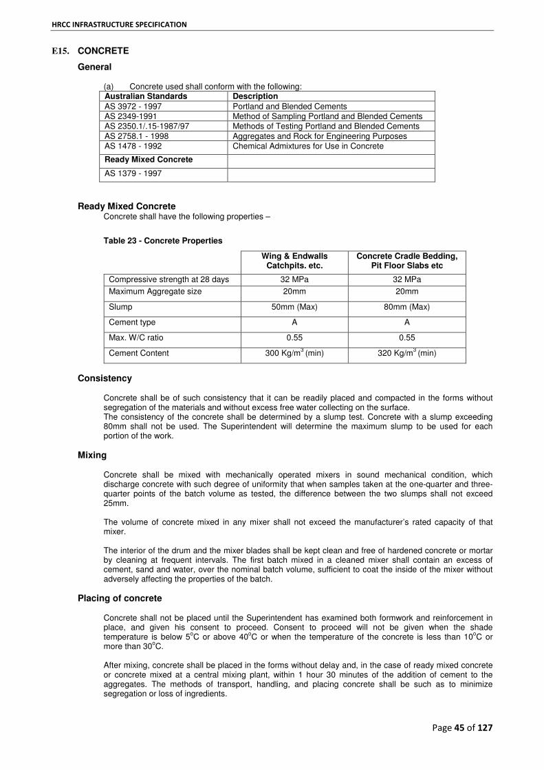
HRCC INFRASTRUCTURE SPECIFICATION
Page 45 of 127
E15. CONCRETE
General
(a) Concrete used shall conform with the following: Australian Standards Description
AS 3972 - 1997 Portland and Blended Cements AS 2349-1991 Method of Sampling Portland and Blended Cements AS 2350.1/.15-1987/97 Methods of Testing Portland and Blended Cements AS 2758.1 - 1998 Aggregates and Rock for Engineering Purposes AS 1478 - 1992 Chemical Admixtures for Use in Concrete
Ready Mixed Concrete
AS 1379 - 1997
Ready Mixed Concrete Concrete shall have the following properties –
Table 23 - Concrete Properties
Wing & Endwalls Catchpits. etc.
Concrete Cradle Bedding, Pit Floor Slabs etc
Compressive strength at 28 days 32 MPa 32 MPa
Maximum Aggregate size 20mm 20mm
Slump 50mm (Max) 80mm (Max)
Cement type A A
Max. W/C ratio 0.55 0.55
Cement Content 300 Kg/m3
(min) 320 Kg/m3
(min)
Consistency
Concrete shall be of such consistency that it can be readily placed and compacted in the forms without segregation of the materials and without excess free water collecting on the surface. The consistency of the concrete shall be determined by a slump test. Concrete with a slump exceeding 80mm shall not be used. The Superintendent will determine the maximum slump to be used for each portion of the work.
Mixing
Concrete shall be mixed with mechanically operated mixers in sound mechanical condition, which discharge concrete with such degree of uniformity that when samples taken at the one-quarter and three-quarter points of the batch volume as tested, the difference between the two slumps shall not exceed 25mm. The volume of concrete mixed in any mixer shall not exceed the manufacturer’s rated capacity of that mixer. The interior of the drum and the mixer blades shall be kept clean and free of hardened concrete or mortar by cleaning at frequent intervals. The first batch mixed in a cleaned mixer shall contain an excess of cement, sand and water, over the nominal batch volume, sufficient to coat the inside of the mixer without adversely affecting the properties of the batch.
Placing of concrete
Concrete shall not be placed until the Superintendent has examined both formwork and reinforcement in place, and given his consent to proceed. Consent to proceed will not be given when the shade temperature is below 5
oC or above 40
oC or when the temperature of the concrete is less than 10
oC or
more than 30oC.
After mixing, concrete shall be placed in the forms without delay and, in the case of ready mixed concrete or concrete mixed at a central mixing plant, within 1 hour 30 minutes of the addition of cement to the aggregates. The methods of transport, handling, and placing concrete shall be such as to minimize segregation or loss of ingredients.

HRCC INFRASTRUCTURE SPECIFICATION
Page 46 of 127
Concrete shall not be placed under water or dropped through a distance greater than 1.5m without the consent of the Superintendent. Depositing a large quantity of concrete at any point and moving it or working it along the forms will not be permitted. Concrete which has developed its initial set, or which has not been placed in the forms and compacted within 20 minutes after discharge from the agitator or on-site mixer, shall not be used. Concrete shall be placed in one continuous operation between ends of members and construction joints, and within such intervals of time that the contact surface of the preceding concrete is still in a plastic condition.
Compaction of Concrete
During and immediately after the placing operation concrete shall be thoroughly compacted by tamping, vibration, or other means approved by the Superintendent. During compaction, neither reinforcement nor formwork shall be displaced. Care shall be taken to fill every part of the forms, to force and concrete under and around the reinforcement, to work coarse aggregate back from form surfaces and faces, and to eliminate voids. Vibration shall be supplemented by such hand tamping as is necessary to achieve these aims. Vibrations shall be of type and design approved by the Superintendent, and shall have a minimum frequency of vibration of 100 Hz. The intensity of vibration shall be such as to visibly affect a mass of concrete having a slump between 20 and 30mm over a radius of at least 0.5m. Vibration shall be applied to freshly deposited concrete. The vibrators shall be inserted into and withdrawn from the concrete slowly. The vibration shall be of sufficient duration and intensity to thoroughly compact the concrete, but shall not be continued so as to cause segregation or produce localized areas of grout. Application of vibrators shall be at points uniformly spaced and not farther apart than twice the radius over which the vibration is visibly effective. Vibration shall not be applied directly or through the reinforcement to sections or layers of concrete which have hardened to the degree that the concrete ceases to be plastic under vibration. It shall not be used to make concrete flow in the forms over distances so great as to cause segregation.
Construction Joints
Construction joints shall be constructed where shown on the plans. Where it is necessary to construct such a joint in a position not shown on the plans, it shall be constructed at a location and in a manner approved or directed by the Superintendent. Joints in the concrete due to stopping work shall be avoided as far as possible. Before placing new concrete against concrete which has set, the forms shall be re tightened if necessary and the surface of the set concrete shall be roughened and cleaned of foreign matter, laitance, and loose material. Immediately prior to placing further concrete the contact surface shall be covered uniformly with a thin coat of cement water paste of creamy consistency. This surface preparation work shall be completed to the satisfaction of the Superintendent before concreting proceeds.
Curing
Until hard set has occurred, freshly finished surfaces shall be effectively protected from rain or injury from other sources. Concrete surfaces exposed to conditions which might cause premature drying shall be protected for a period of not less than 24 hours after placing the concrete. The surface shall be kept moist in a manner approved by the Superintendent, either by flushing or sprinkling, or by covering with impermeable material or permeable material kept moist. Curing compounds may be used only with the consent of the Superintendent. When in the opinion of the Superintendent, frosts or freezing temperatures are likely, special precautions shall be taken to maintain the concrete temperature at the surface of the setting concrete above 5
oC.
Removal of Forms
Forms shall not be removed without the permission of the Superintendent.
Finish of Exposed Surfaces
Exposed surfaces shall be true and free from depressions or projections. Rough or porous areas and holes shall be filled with mortar. Bolts, wires and other items passing through the concrete to hold the forms shall be cut off or set back 25mm below the surface and resultant holes shall be filled with mortar.

HRCC INFRASTRUCTURE SPECIFICATION
Page 47 of 127
Defective Concrete
The Contractor shall be fully responsible for the adequacy of forms, and for employing effective methods of mixing, placing, protecting and curing concrete. Approval of any such work or methods by the Superintendent will not relieve the Contractor of this responsibility. Concrete not placed and completed in accordance with this specification or which, in the opinion of the Superintendent, is defective shall be removed within the limits assigned by the Superintendent and replaced by the Contractor at his expense.
Testing
(a) All tests shall be conducted in accordance with the relevant Australian Standards.
Test Test Method No
Cement Content 140.01
Test for Incidental Concrete 401
(b) Where test cylinders are made by the Superintendent, the Contractor shall provide suitable storage for them at the site where they shall be kept undisturbed and shelter from sun and
(c) wind, and protected from extremes of temperature. The Superintendent will remove the cylinders not later than four days after casting.
STEEL REINFORCEMENT
All steel reinforcement shall be fabricated, cut and placed to the tolerances and standards as stated in AS 3600 - 1994, Concrete Structures and as shown on the Drawings. Placing of Reinforcement
Reinforcement shall be carefully formed to the dimensions and shapes shown on the drawings. For mild steel reinforcing bars cold bends shall be made around a pin of diameter not less than four times the nominal diameter of the bars. Reinforcement shall not be bent or straightened in a manner that will damage the material. Where splicing of reinforcement is necessary, this shall be done either by overlapping the bars or mesh for a distance not less than 40 times the nominal diameter of the bars or wires being lapped, or by welding in such a manner as to maintain the full strength of the bars. Reinforcement shall be accurately placed in the positions shown on the drawings. During the placing and compacting of concrete, reinforcement shall be securely held by methods approved by the Superintendent. Bars shall be tied at all intersections except where spacing is less than 300mm in any direction when alternative intersections shall be tied. Unless otherwise shown on the drawings, the minimum clear cover to reinforcement shall be 1.5 times the diameter of the bars or 50mm whichever is greater. The placing of bars or layers of fresh concrete as the work progresses and the adjustment of bars during the placing of concrete will not be permitted. Slab reinforcement shall be supported on bar chairs placed at a maximum spacing of 600mm. For off form concrete surfaces, plastic tipped wire bar chairs shall be used. No metal part of any device used for connecting bars or for maintaining reinforcement in the correct position shall remain permanently within the specified minimum cover to the reinforcement.
Welding of Reinforcement
Welding shall not be carried out on bar reinforcement unless shown on the Drawings or approved by the Superintendent. If approved, welding shall comply with AS 1554.3 - 1983, Welding of Reinforcing Steel.
Fittings
The Contractor shall make allowances for pipework penetrations, services penetrations, fixtures, cast iron metalwork, and pockets for anchor bolts.
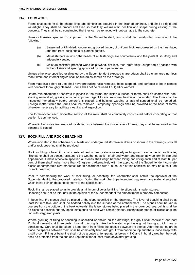
HRCC INFRASTRUCTURE SPECIFICATION
Page 48 of 127
E16. FORMWORK
Forms shall conform to the shape, lines and dimensions required in the finished concrete, and shall be rigid and watertight. They shall be braced and fixed so that they will maintain position and shape during casting of the concrete. They shall be so constructed that they can be removed without damage to the concrete. Unless otherwise specified or approved by the Superintendent, forms shall be constructed from one of the following:
(a) Seasoned or kiln dried, tongue and grooved timber; of uniform thickness, dressed on the inner face, and free from loose knots or surface defects.
(b) Metal shutters in which the heads of all fastenings are countersunk and the joints flush fitting and adequately sealed.
(c) Moisture resistant pressed wood or plywood, not less than 5mm thick, supported or backed with timber of size and spacing approved by the Superintendent.
Unless otherwise specified or directed by the Superintendent exposed sharp edges shall be chamfered not less than 20mm and internal angles shall be filleted as shown on the drawings. Form materials before re-use shall have protruding nails removed, holes stopped, and surfaces to be in contact with concrete thoroughly cleaned. Forms shall not be re-used if bulged or warped. Before reinforcement or concrete is placed in the forms, the inside surfaces of forms shall be coated with non-staining mineral oil, grease, or other approved agent to ensure non-adhesion of the mortar. The form shall be inspected immediately before concrete is placed, and bulging, warping or lack of support shall be remedied. Foreign matter within the forms shall be removed. Temporary openings shall be provided at the base of forms wherever necessary to facilitate cleaning and inspection. The formwork for each monolithic section of the work shall be completely constructed before concreting of that section is commenced. Where timber spreaders are used inside forms or between the inside faces of forms, they shall be removed as the concrete is placed.
E17. ROCK FILL AND ROCK BEACHING
Where indicated in the schedule of culverts and underground stormwater drains or shown in the drawings, rock fill and/or rock beaching shall be provided. Rock for filling or beaching shall consist of field or quarry stone as nearly rectangular in section as is practicable; ‘The stone shall be dense, resistant to the weathering action of air and water, and reasonably uniform in size and appearance. Unless otherwise specified all stones shall weigh between 22 kg and 68 kg each and at least 60 per cent of them shall’ weigh more than 45 kg each. Alternatively with the approval of the Superintendent concrete blocks of comparable size manufactured in accordance with Clause D17 of this specification may be substituted for rock beaching. Prior to commencing the work of rock filling, or beaching, the Contractor shall obtain the approval of the Superintendent to the proposed materials. During the work, the Superintendent may reject any material supplied which in his opinion does not conform to the specification. Rock fill shall be placed so as to provide a minimum of voids by filling interstices with smaller stones. Beaching shall not be laid, until in the opinion of the Superintendent the embankment is properly compacted. In beaching, the stones shall be placed at the slope specified on the drawings. The layer of beaching shall be at least 225mm thick and shall be bedded solidly into the surface of the embankment. The stones shall be laid in courses from the bottom of the bank upwards, the larger stones being placed in the lower courses. Joints shall be as close as possible but any open joints shall be filled with smaller stones. Rectangular stones or blocks shall be laid with staggered joints. Where grouting of filling or beaching is specified or shown on the drawings, the grout shall consist of one part Portland cement and three parts of sand, thoroughly mixed with water to produce grout having a thick creamy consistency. Care shall be taken to keep earth from filling the spaces between the stones. After the stones are in place the spaces between them shall be completely filled with grout from bottom to top and the surface swept with a stiff broom Filling or beaching shall not be grouted at temperatures below 4.4
oC and in hot dry weather the work
shall be protected from the sun and kept moist for at least three days after grouting.

HRCC INFRASTRUCTURE SPECIFICATION
Page 49 of 127
E18. EXIT AND ENTRY CHANNELS
Where necessary to ensure easy flow into and out of the culverts, channels of sufficient area to take the flow of water shall be excavated to the shape and alignment shown on the drawings or to the approval of the Superintendent. Channels shall be of regular shape, and care shall be taken to prevent excavation below the required grade. Any such low areas shall be filled with suitable material and thoroughly compacted by the Contractor at his expense. Material obtained from channel excavation shall be disposed of to the approval of the Superintendent.
E19. UNSATISFACTORY WORK
Any work carried out by the Contractor, which in the opinion of the Superintendent does not comply with the requirements of this specification, shall not be paid for and rejected concrete shall be removed by the Contractor at his own expense.
UNDERGROUND STORMWATER PIPES The following standards apply to all underground stormwater pipes.
Type of Pipe Standard (& as amended)
1 Concrete Pipes AS 4058 - 1992 2 PVC pipes (for property connections) AS 1254 - 1991
E20. AGE OF PIPES
No pipe shall be transported from the place of manufacture until the minimum 28 days strength has been attained, or without the approval of the Superintendent or the representative.
E21. HANDLING OF PIPE SECTIONS
The Contractor shall employ adequate means of handling pipe sections, and shall be responsible for all damages done to these in unloading from delivery trucks, cartage to the site and laying in positions. All pipe sections damaged in these operations shall be replaced by Contractor at Contractor’s expense.
E22. CONFORMITY WITH DRAWINGS
The Contractor shall set out drainage works in accordance with the drawings or as specified or as directed by the Superintend.
E23. DE-WATERING
Any de-watering required shall be carried out by the contractor at contractor’s expense as directed by the Superintendent.
E24. EXCAVATION FOR PIPE LAYING
Excavation for installation of pipes shall include all excavation necessary to prepare the pipe foundation, and to provide the full specified depth of pipe bedding. Trenches shall be excavated to a minimum width (external diameter of the pipes + 2 x 300mm) sufficient to allow for proper jointing of the pipe sections and thorough compaction of the bedding and backfill material under and around the pipe. Where practicable trench walls shall be vertical. Excavations shall be supported by satisfactory means to ensure the safety of workmen and traffic. The base of the completed trench shall be firm and uniform for its full length so as to avoid any unequal settlement along the length of a pipe. Excess excavation below the required level shall be backfilled at the Contractor's expense with sand, gravel or other materials directed by the Superintendent's Representative, and thoroughly compacted. No claim will be considered on the account of any rock or other materials met within the trench excavation. Where directed and authorised in writing by the Superintendent's Representative, soft, wet or unstable areas below the level of the minimum required thickness of pipe bedding shall be excavated and backfilled with gravel or other approved stable material spread in layers not exceeding 150mmloose thickness and thoroughly compacted to ensure an unyielding foundation.

HRCC INFRASTRUCTURE SPECIFICATION
Page 50 of 127
Payment for authorised excavation and replacement of unsuitable material below the level of the minimum required thickness of pipe bedding shall be made at the schedule rate applicable for this work. Wet or unstable areas of any depths which, in the opinion of the Superintendent’s Representative, have been caused by the Contractor's negligence or improper methods shall be excavated and replaced with gravel or other approved stable material spread and compacted as above by the Contractor at his own expense.
E25. SUPPORTS FOR TRENCH WALLS
The Contractor shall supply and fix at his own expense strong and sufficient timber, when necessary, to support the side sand/or bottom of the excavations in open cut or trench in accordance with the relevant codes of practice and to the satisfaction of the Superintendent’s Representative. The Superintendent's Representative may order the ground to be close timbered wherever it may appear to him to be necessary, and no extra charge shall be made for this by the Contractor. Notwithstanding the above requirements, procedures and precautions as set out in the WorkSafe Victoria publication Safety Precautions in Trenching Operations are to be adhered to. The Contractor shall be responsible for any injury to workers, and any consequential damage caused or arising out of the removal of timbering, and advice, permission or approval given by the Superintendent's Representative relative to the removal of timbering shall not relieve the Contractor from the responsibility here defined. Before commencing any excavation in which the depth of face exceeds 1.5 metres, or any tunnelling operation, the Contractor shall read, understand and follow WorkSafe Victoria publication, “Safe Precautions in Trenching Operations”. Contractor shall be liable for all accidents and claims arising from such trenching operations that occurs without adequate safety measures being undertaken before and while trenching is carried out.
10.10 PIPE BEDDING AND LAYING
E26. PIPE BEDDING & LAYING
The Contractor shall lay and joint accurately all pipes to line, level and grade and shall be particularly careful to lay all pipes with the top as indicated by the manufacturer in its correct position. Care must be taken to see that the invert of each pipe length at the joints fit accurately with the next. Pipes shall only be laid in a dry trench. All pipes shall be bedded so as to bear evenly for the full length on a 50mm compacted bed of 20mm crushed rock class 3 or 5 to7mm aggregate. Pipe laying shall commence at the outlet unless otherwise directed by the Superintendent’s Representative. Pipes shall not be laid before the trench and bed has been inspected and approved by the Superintendent’s Representative.
E27. JOINTING OF PIPES
Spigot and socket pipes and interlocking joint pipes shall be properly jointed with cement mortar. Rubber ring jointed pipes shall be jointed with a neatly fitting rubber ring. In the case of internally jointed pipes, the mortar shall be struck off flush with the bore of the pipe.
E28. HOUSEHOLD / PROPERTY DRAINS
The Contractor shall supply and lay house drains associated with easement drainage to each allotment where shown on the drawings or where directed by the Superintendent’s Representative and shall allow for connection of existing house drains from property line to existing drain pipe or kerb & channel. Property Inlet Pits are to be located at low points of each allotment in accordance with the standard drawings or where directed by the Superintendent’s Representative. Where connections are to be made to existing drainage pipes the use of manufactured “T” piece subject to approval by the Superintendent’s Representative or as per standard drawings.
E29. FINE CRUSH ROCK AROUND PIPES
After pipe laying and jointing has been approved by the Superintendent’s Representative, the Contractor shall place a layer of either 20mm crushed rock class 3 or 5 to 7mm aggregate and or other material around the pipe and up to a level equal to half the diameter of the pipe. Such material shall be mechanically rammed in layers so as to ensure that it is compacted to a density of not less than 95%. AS. Standard Maximum Dry Density under and around the pipes. If necessary water may be added to the fine crushed rock to achieve the desired compaction. Before any backfilling is commenced the material around the pipes shall be approved by the Superintendent’s Representative.

HRCC INFRASTRUCTURE SPECIFICATION
Page 51 of 127
E30. BACK-FILLING
No joints are to be covered or trench backfilled until pipe laying and jointing has been approved by the Superintendent’s Representative. It shall be the Contractor's responsibility to ensure the inspection and approval of the pipe drain prior to the backfilling. The Contractor shall backfill the pipe trench with approved material of uniform composition as specified and without organic material. The maximum size of backfill material shall be 150mm.Each trench shall be backfilled in layers not more than 150mmloose thickness. Each layer shall be rammed with an approved type of mechanical rammer to the following densities and with a uniform moisture content in the range 85% to 115% of the optimum moisture content determined in the Standard Compaction Test :- (a) Within paved areas - not less than 100% of A.S. Standard Maximum Dry Density. (b) Within other areas - not less than 95% of A.S. Standard Maximum Dry Density.
The Contractor shall be required to provide Compaction Test results to the Superintendent’s Representative and shall allow in the amount tendered for drainage, to engage a Soils Consultant or independent N.A.T.A. laboratory ( approved by the Superintendent’s Representative) to carry out compaction testing on trench backfill. Within paved areas, the tests shall be carried out (where the depth of backfilling exceeds 1.00m ) at 15m intervals along the length of the trench and at 1.00m depth intervals and subgrade level. At least one set of tests shall be taken between pits on each pipeline. Within other areas, the tests shall be carried out (where the depth of backfilling exceeds 1.00m) at 20m intervals along the length of the trench and at 1.00m depth intervals and subgrade level. At least one set of tests shall be taken between pits on each pipeline. It will be an expressed Condition of this Contract that the Contractor allows for the cost of compaction testing in accordance with this Clause in the tendered price for the works. The Superintendent’s Representative may require additional testing over and above the nominated testing interval set out above. The Contractor shall be reimbursed from the prime cost sum for material and compaction testing for these tests. The costs for testing backfill which is found to be faulty together with the cost of replacing and re-compaction of the faulty backfill material shall be borne by the Contractor. When high density polyethylene or uPVC pipe is being used the contractor shall cover the pipe to a depth of 150mm above the pipe with bedding material.
E31. PIPE DRAINS UNDER PAVED AREAS
Backfilling of pipe trenches under areas to be paved for roadways, drive-ways, directly behind kerb and channel, or car parks shall consist of either 20mm Class 2 crushed rock or 5 to 7mm Aggregate for the full depth of the trench extending to the subgrade level, unless otherwise noted on the drawings.
E32. CONSTRUCTION LOADING ON PIPES AND PIPE CULVERTS
Care must be taken to ensure that at least the minimum compacted thickness of cover has been provided over any pipe or pipe culvert before allowing construction traffic to cross the drainage line. Temporary embankments may be required to provide the necessary cover and to protect the works.
E33. DRAINAGE PITS
Pits shall be constructed at the locations shown on the drawings and to the dimensions and requirements shown on the relevant Standard Drawings. Provision shall be made for the connection of all stormwater drainage pipes and subsurface drains as shown on the drawings. The ends of pipes entering or leaving pits shall be neatly trimmed off flush with the inside walls and pointed up with cement mortar and at exit pipe from pit, rounded with a minimum radius of 50mm. Pit walls may be poured against free standing excavation, provided there is no possibility of earth being dislodged onto freshly deposited concrete. However, the uppermost section of the outside of pits walls shall be formed for a depth of 150mm. All forms shall be fixed and rigidly braced and shall be approved by the Superintendent’s Representative prior to concrete placement. Where possibility of earth dislodgement exists, the whole of the outside of pit walls shall be formed.
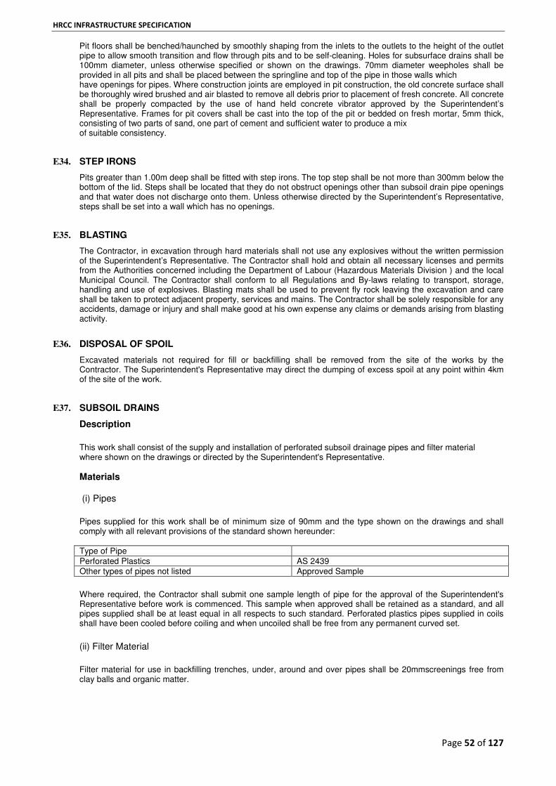
HRCC INFRASTRUCTURE SPECIFICATION
Page 52 of 127
Pit floors shall be benched/haunched by smoothly shaping from the inlets to the outlets to the height of the outlet pipe to allow smooth transition and flow through pits and to be self-cleaning. Holes for subsurface drains shall be 100mm diameter, unless otherwise specified or shown on the drawings. 70mm diameter weepholes shall be provided in all pits and shall be placed between the springline and top of the pipe in those walls which have openings for pipes. Where construction joints are employed in pit construction, the old concrete surface shall be thoroughly wired brushed and air blasted to remove all debris prior to placement of fresh concrete. All concrete shall be properly compacted by the use of hand held concrete vibrator approved by the Superintendent’s Representative. Frames for pit covers shall be cast into the top of the pit or bedded on fresh mortar, 5mm thick, consisting of two parts of sand, one part of cement and sufficient water to produce a mix of suitable consistency.
10.19 STEP IRONS
E34. STEP IRONS
Pits greater than 1.00m deep shall be fitted with step irons. The top step shall be not more than 300mm below the bottom of the lid. Steps shall be located that they do not obstruct openings other than subsoil drain pipe openings and that water does not discharge onto them. Unless otherwise directed by the Superintendent’s Representative, steps shall be set into a wall which has no openings.
E35. BLASTING
The Contractor, in excavation through hard materials shall not use any explosives without the written permission of the Superintendent’s Representative. The Contractor shall hold and obtain all necessary licenses and permits from the Authorities concerned including the Department of Labour (Hazardous Materials Division ) and the local Municipal Council. The Contractor shall conform to all Regulations and By-laws relating to transport, storage, handling and use of explosives. Blasting mats shall be used to prevent fly rock leaving the excavation and care shall be taken to protect adjacent property, services and mains. The Contractor shall be solely responsible for any accidents, damage or injury and shall make good at his own expense any claims or demands arising from blasting activity.
E36. DISPOSAL OF SPOIL
Excavated materials not required for fill or backfilling shall be removed from the site of the works by the Contractor. The Superintendent's Representative may direct the dumping of excess spoil at any point within 4km of the site of the work.
10.22 SUBSOIL DRAINS
E37. SUBSOIL DRAINS
Description
This work shall consist of the supply and installation of perforated subsoil drainage pipes and filter material where shown on the drawings or directed by the Superintendent's Representative.
Materials (i) Pipes
Pipes supplied for this work shall be of minimum size of 90mm and the type shown on the drawings and shall comply with all relevant provisions of the standard shown hereunder: Type of Pipe Perforated Plastics AS 2439 Other types of pipes not listed Approved Sample
Where required, the Contractor shall submit one sample length of pipe for the approval of the Superintendent's Representative before work is commenced. This sample when approved shall be retained as a standard, and all pipes supplied shall be at least equal in all respects to such standard. Perforated plastics pipes supplied in coils shall have been cooled before coiling and when uncoiled shall be free from any permanent curved set.
(ii) Filter Material
Filter material for use in backfilling trenches, under, around and over pipes shall be 20mmscreenings free from clay balls and organic matter.

HRCC INFRASTRUCTURE SPECIFICATION
Page 53 of 127
E38. SUBSOIL DRAIN PIPE INSTALLATION
Trenches shall be excavated to the dimensions and grade required by the drawings or directed by the Superintendent’s Representative. Pipes shall be a minimum of 750mm below the top of the kerb. The minimum trench width shall be the pipe diameter plus 100mm with the maximum width of trench of 300mm and the pipes shall be laid true to line and grade to discharge into pits or in accordance with the drawings. The pipes of the type and size specified shall be laid firmly embedded in the bedding material with adjacent lengths butted together or connected where necessary. Open joints shall be suitably wrapped to permit entry of water. Perforated or slotted pipes shall be laid preferably without the openings facing down. Subsoil drain shall not be laid more than 150mm below any stabilised subgrades unless otherwise directed by the Superintendent’s Representative. After the pipe installation has been inspected and approved, 20mm screenings shall be placed to within 150mm of the top of the kerb, care being taken not to displace the pipe or the covering at open joints The final 150mm shall be filled with approved top soil material, except in paved areas where the top of the screenings is level with the sub-base of the pavement.
E39. INPECTION OF DRAINAGE LINES
Unless approved otherwise by the Superintendent, all drainage lines constructed shall be inspected, after completion of earthworks to subgrade level and prior to construction of pavement layers, by an independent testing organisation using closed circuit television (CCTV). Reporting of the CCTV inspections shall be in accordance with WSA 05 2013 – Conduit Inspection Reporting Code of Australia, published by Water Services Association of Australia. The report shall be provided to the Superintendent, with a copy of the CCTV record and a summary of the location of any defects detected by the survey. Any sections of damaged pipe shall be removed and replaced prior to construction of the pavement layers and a further CCTV survey shall be undertaken to verify correction of the defects.

HRCC INFRASTRUCTURE SPECIFICATION
Page 54 of 127
PART F - FOOTPATHS
REINFORCED CONCRETE F1. GENERAL
The whole of the works to be carried out under the contract shall conform to the requirements of this specification, the accompanying plans and standard drawings (HRCC - STD 3 / 32 or 39 as relevant), and shall be carried out under the direction and to the satisfaction of the Superintendent.
F2. EXCAVATION
The Contractor shall excavate to such line and level as may be necessary for the, proper completion of the works. Materials so excavated shall be deposited clear of the works and shall be later removed by the Contractor.
F3. FOUNDATIONS
Foundations for concrete work shall be neatly cut true to line and level and properly consolidated before work proceeds. A bed of sand 50 millimetres in thickness shall be spread, watered and consolidated along the bottom of all excavations before the concrete is placed.
F4. SUPPLY OF MATERIALS
Concrete aggregate shall be obtained from the McKenzie Creek area and shall consist of 20 nm crushed rock concrete aggregate. Sand shall be of good quality obtained from Dooen or alternatively quarry dust may be used in lieu of sand. Water for mixing, curing etc. can be supplied from the water mains and a hydrant will be made available to the Contractor on application, at no cost. The Contractor shall supply all materials required for the work. All materials supplied shall be of quality which conforms to Australian Standards for concrete in building.
F5. CONCRETE
General (a) Concrete & Ready Mixed Concrete used shall conform with the following Australian Standards:
Description Standard
Portland and Blended Cements AS 3972 - 1997
Method of Sampling Portland and Blended Cements AS 2349-1991
Methods of Testing Portland and Blended Cements AS 2350.1/.15-1987/97
Aggregate & Rock for Engineering Purposes AS 2758.1 - 1998
Chemical Admixtures for Use in Concrete AS 1478 - 1992
Ready Mixed Concrete AS 1379 -1997
The mixing and delivery of ready mixed concrete or concrete mixed in a central plant shall comply with:
Property Value
Compressive strength at 28 days: 20 MPa
Max. Aggregate size: 20mm
Slump: 80mm
Cement type: A
Max W/C ratio: 0.55
Cement Content: 320 kg/m (min.)

HRCC INFRASTRUCTURE SPECIFICATION
Page 55 of 127
Consistency
Concrete shall be of such consistency that it can be readily placed and compacted in the forms without segregation of the materials and without excess free water collecting on the surface. The consistency of the concrete shall be determined by a slump test. Concrete with a slump exceeding 80mm shall not be used. The Superintendent will determine the maximum slump to be used for each portion of the work.
Mixing
Concrete shall be mixed with mechanically operated mixers in sound mechanical condition, which discharge concrete with such degree of uniformity that when samples taken at the one quarter and three quarter points of the batch volume as tested, the difference between the two slumps shall not exceed 25mm. The volume of concrete mixed in any mixer shall not exceed the manufacturer’s rated capacity of that mixer. The interior of the drum and the mixer blades shall be kept clean and free of: hardened concrete or mortar by cleaning at frequent intervals. The first batch mixed in a cleaned mixer shall contain an excess of cement, sand and water over the nominal batch volume, sufficient to coat the inside of the mixer without adversely affecting the properties of the batch. The water used shall be free from all substances harmful to concrete and its reinforcement. Each batch shall be completely discharged from the mixer before any materials are placed therein for the next mix.
Placing the Concrete
Concrete shall not be placed until the Superintendent has examined both formwork and reinforcement in place, and given his consent to proceed. Consent to proceed will not be given when the shade temperature is below 5°C or above 40°C or when the temperature of the concrete is less than 10°C or more than 30°C. After mixing, concrete shall be placed in the forms without delay and, in the case of ready mixed concrete or concrete mixed at a central mixing plant, within 1 hour 30 minutes of the addition of cement to the aggregates. The methods of transport, handling, and placing concrete shall be such as to minimize segregation or loss of ingredients. Concrete shall not be placed under water or dropped through a distance greater than 1.5m without the consent of the Superintendent. Depositing a large quantity of concrete at any point and moving it or working it along the forms will not be permitted. Concrete which has developed its initial set, or which has not been placed in the forms and compacted within 20 minutes after discharge from the agitator or onsite mixer, shall not be used. Concrete shall be placed in one continuous operation between ends of members and construction joints, and within such intervals of time that the contact surface of the preceding concrete is still in a plastic condition.
Compaction of Concrete
During and immediately after the placing operation concrete shall be thoroughly compacted by tamping or other means approved by the Superintendent. During compaction neither reinforcement, nor formwork shall be displaced. Care shall be taken to fill every part of the forms, to force the concrete under and around, the reinforcement, to work coarse aggregate back from form surfaces and faces, and to eliminate voids. Vibration shall be supplemented by such hand tamping as is necessary to achieve these aims.
Construction Joints
Construction joints shall be constructed where shown on the plans. • Where it is necessary .to construct such a joint in a position not shown on the plans, it shall be constructed at a location and in a manner approved or directed by the Superintendent. Joints in the concrete-due to stopping-work shall be avoided as far as possible. Before placing concrete against concrete which has set, the forms shall be re-tightened if necessary and the surface of the set concrete shall be roughened and cleaned of foreign matter, laitance, and loose

HRCC INFRASTRUCTURE SPECIFICATION
Page 56 of 127
material. Immediately prior to placing further concrete the contact surface shall be covered uniformly with a thin coat of cement-water paste of creamy consistency. This surface preparation work shall be completed to the satisfaction of the Superintendent before concreting proceeds.
Contraction Joints
To form a contraction joint, a piece of pinus timber measuring 20mm (tolerance 1mm) square shall be nailed across and at right angles to the formwork for the sides, with its lower edge at the level of the prepared base for the concrete. Nails shall be driven into the top edge of the formwork to mark the location of the timber. After pouring the concrete a grooving tool shall be used to make a groove at least 20mm deep directly over the pinus board. Reinforcing shall be continuous through the joint, and shall be at least 25mm clear of the lower timber groove former. Reinforcing MUST NOT be lapped over a contraction joint, but the overlapping portion at joins in reinforcing must be kept at least 150mm away from the contraction joints.
Spacing of Contraction Joints
Where ever there is; irregularity of section, caused by telecommunication cable boxes or other similar obstruction, contraction joints shall be so placed that the angles between any two adjacent sides on any one shall be not less than 800 nor more than 1700 measured internally. Re-entry angles on any block shall not be permitted. At other places joints shall be placed at not more than 1800mm spacing except in vehicular crossing sections where there shall be no joints of any kind.
Expansion Joints
Expansion joints shall be constructed as shown in the drawings and shall be placed at preferably 12 metre intervals with a maximum interval of 15 metres. These joints shall be placed as far as practicable at dividing fence line between properties and clear of driveways. Expansion joint material shall be supplied by the Contractor who shall allow for placing such material at his own expense and in strict accordance with instructions. All reinforcement shall be placed as shown in the drawings. Except for the 10mm diameter bars, the reinforcement shall terminate 75mm from each side of every expansion joint. One end the 10mm diameter bar shall be cast in the concrete and. the other end greased and sleeved in 10mm diameter P.V.C. pipe to allow for longitudinal movement of the slab. Concrete shall be 150mm thick at expansion joints, terminating 150mm past expansion rods. Where it is necessary to interrupt the laying of concrete for meal breaks or at the end of the days section an expansion joint shall be placed in accordance with the plan.
Curing
Until hard set has occurred, freshly finished surfaces shall be effectively protected from rain or injury from other sources. Concrete surfaces exposed conditions which might cause premature drying shall be protected for a period of not less than 24 hours after placing the concrete. The surface shall be kept moist in a manner approved by the Superintendent, either by flushing or sprinkling, or by covering with impermeable material or permeable material kept moist. Curing compounds may be used only with the consent of the Superintendent. When in the opinion of the Superintendent, frosts or freezing temperatures are likely, special precautions shall be taken to maintain the concrete temperature at the surface of the setting concrete above 5°C.
Removal of Forms
Forms shall not be removed without the permission of the Superintendent.
Finish of Exposed Surfaces
Exposed surfaces shall be true and free from depressions or projections. Rough or porous areas and holes shall be filled with mortar Bolts, wires and other items passing through the concrete to hold the forms shall be cut off or set back 25mm below the surface and any resultant holes shall be filled with mortar.

HRCC INFRASTRUCTURE SPECIFICATION
Page 57 of 127
Defective Concrete
The Contractor shall be fully responsible for the adequacy of forms, and for employing effective methods of mixing, placing, protecting and curing concrete. Approval of any such work or methods by the Superintendent will not relieve the Contractor of this responsibility. Concrete not placed and completed in accordance with this specification or which, in the opinion of the Superintendent, is defective shall be removed within the limits assigned by the Superintendent and replaced by the Contractor at his expense.
Testing
(a) All tests shall be conducted in accordance with the relevant Australian Standard.
Test Test Method No.
Cement Content 140.01
Test for Incidental Concrete 401
(b) Where test cylinders are made by the Superintendent, the Contractor shall provide suitable storage for them at the site where they shall be kept undisturbed and shelter from sun and wind, and protected from extremes of temperature. The Superintendent will remove the cylinders not later than four days after casting.
F6. STEEL REINFORCEMENT
Placing of Reinforcement
Reinforcement shall be carefully formed to the dimensions and shapes shown on the drawings. For mild steel reinforcing bars cold bends shall be made around a pin of diameter not less than four times the nominal diameter of the bars. Reinforcement shall not be bent or straightened in a manner that will damage the material. Where splicing of reinforcement is necessary, this shall be done either by overlapping the bars or mesh for a distance not less than 40 times the nominal diameter of the bars or wires being lapped, or by welding in such a manner as to maintain the full strength of the bars. Reinforcement shall be accurately placed in the positions shown on the drawings. During the placing and compacting of concrete, reinforcement shall be securely held by methods approved by the Superintendent. Bars shall be tied at all intersections except where spacing is less than 300mm in any direction when alternate intersections shall be tied. Unless otherwise shown on the drawings, the minimum clear cover to reinforcement shall be 1.5 times the diameter of the bars or 50mm whichever is greater. The placing of bars or layers of fresh concrete as the work progresses and the adjustment of bars during the placing of concrete will not be permitted. Reinforcement shall be continuous throughout the length of the work except at:
(i) Joins in the reinforcement where the longitudinal bars only shall be overlapped by at least 150mm.
(ii) Expansion joints where it shall terminate 75mm each side of such joints.
Slab reinforcement shall be supported on bar chairs placed at a maximum spacing of 600mm. For off form concrete surfaces, plastic tipped wire bar chairs shall be used. No metal part of any device used for connecting bars or for maintaining reinforcement in the correct position shall remain permanently within the specified minimum cover to the reinforcement.
Welding of Reinforcement
Welding shall not be carried out on bar reinforcement unless shown on the Drawings or approved by the Superintendent. If approved, welding shall comply with AS 1554 Part 3, Welding of Reinforcing Steel.
Fittings
The Contractor shall make allowance for pipework penetration, services penetration, fixtures, cast iron metalwork, and pockets for anchor bolts.

HRCC INFRASTRUCTURE SPECIFICATION
Page 58 of 127
F7. FORMWORK
All forms, templates, screeds etc. required for the proper placing of the concrete shall be supplied by the Contractor. Forms shall conform to the shape, lines and dimensions required in the finished concrete, and shall be rigid and watertight. They shall be braced and fixed so that they will maintain position and shape during casting of the concrete. They will be so constructed that they can be removed without damage to the concrete. Unless otherwise specified or approved by the Superintendent, forms shall be constructed from one of the following:
(a) Seasoned or kiln dried, tongue and grooved timber, of uniform thickness, dressed on the inner face, and free from loose knots of surface defects.
(b) Metal shutters in which the heads of all fastenings are counter-sunk and the joints flush fitting and adequately sealed.
(c) Moisture resistant pressed wood or plywood, not less than 5mm thick, supported or backed with timber of size and spacing approved by the Superintendent.
Unless otherwise specified or directed by the Superintendent exposed sharp edges shall be chamfered not less than 20mm and internal angles shall be filleted as shown on the drawings. Form materials before re-use shall have protruding nails removed, holes stopped, and surfaces to be in contact with concrete thoroughly cleaned. Forms shall not be re-used if bulged or warped. Before reinforcement or concrete is placed in the forms, the inside surfaces of forms shall be coated with non-staining mineral oil, grease, or other approved agent to ensure non-adhesion of the mortar. The forms shall be inspected immediately before concrete is placed, and bulging, warping or lack of support shall be remedied. Foreign matter within the forms shall be removed. Temporary openings shall be provided at the base of forms wherever necessary to facilitate cleaning and inspection. The formwork for each monolithic section of the work shall be completely constructed before concreting of that section is commenced. Where timber spreaders are used inside forms or between the inside faces of forms, they shall be removed as the concrete is placed.
F8. UNSATISFACTORY WORK
Any work carried out by the Contractor, which in the opinion of the Superintendent does not comply with the requirements of this specification shall not be paid for and rejected concrete shall be removed by the Contractor at his own expense.
F9. EMPLOYMENT OF LABOUR
All workmen employed by the Contractor shall be efficient at their respective tasks and shall be paid at least award rates of pay and shall be covered by insurance under the Worker’s Compensation Act. The Contractor may be required to produce evidence that these requirements have been met before payments shall be made.
F10. VEHICULAR CROSSINGS
The pavement thickness shall be 150mm. (unless directed. otherwise) over the entire width of the vehicular crossings, and an additional 225mm each side of the gateway openings as shown on the drawings. No grooving or construction joints shall be permitted in vehicular crossings.
F11. BACKFILLING
Backfilling and reinstatement along the edges of the pavement shall be done to the approval of the Superintendent. PAVERS
F12. CONTRACTORS RESPONSIBILITY

HRCC INFRASTRUCTURE SPECIFICATION
Page 59 of 127
The Contractor shall be entirely responsible for ensuring that all operations and methods of construction, set out, materials and workmanship are safe, sufficient and in accord with the specifications.
F13. LOCATION OF EXISTING SERVICES
The Contractor will be held responsible for bearing the cost of making good any damage to existing services and mains, whether or not these are shown on drawings. Services in close proximity to proposed works shall be exposed by hand before work is to commence. It is the sole responsibility of the Contractor to fully inform himself of the location of services and to make the necessary provisions.
F14. CLEANING UP
The Contractor shall remove all equipment and debris from the site at the completion of the works of the contract and at the end of the contract. The site shall be left tidy and ready for immediate use. At the end of each working day piles of rubbish shall be removed, leaving the site in a tidy condition.
F15. MAKE GOOD
On completion of the work, the Contractor shall “make good” all footpaths, grassed areas, easements and other surfaces disturbed by the works, do all other necessary repairs, property clean up leave the site in a condition satisfactory to the Project Supervisor. The contract is to meet all costs associated with the removal and dumping of all rubbish and rubble from the site.
F16. EXISTING DRAINS PROTECTION
The Contractor shall cover all stormwater grates and take care to avoid soil entering pits or drains during the site works contract. He shall remove (not by washing down the pipe) any material which enters pits.
F17. SCOPE OF WORKS
- Excavation where required for paving to such line and level as set by the Superintendent which may be necessary for the proper completion of works. - Preparation and compaction of all sub-grades for pavement. - Materials so excavated shall be disposed of by the Contractors directed by the Superintendent. - Supply and construction of crushed rock base courses to pavement areas. Work shall include excavation and filling, as required to achieve necessary sub-grade levels and compaction.
F18. BEDDING
Bedding shall be 25 mm approved sand over the Base Course. F19. SAMPLES
Samples of all paving materials will be subject to inspection by and approval of the Project Supervisor. F20. CONCRETE INTERLOCKING PAVING UNITS
The pavers shall be charcoal grey in colour and be free from cracks, damage to surface, edges and corners. Any damaged pavers are to be removed and replaced at the Contractors expense.
F21. PAVER EDGING TO GARDEN BEDS:
- Where complete pavers are used these are to be interlocked with other paving units using “sides”, “ends” or “halves”. - Where part pavers are installed as a result of required cutting, and interlocking is not satisfactory, a mortar haunching is to be provided, neatly trowel finished and kept 25mm below the finished paving level.
F22. CONCRETE INTERLOCKING PAVING:
- Interlocking paving is to be laid on a 100mm minimum depth compacted 20mm FCR sub-base and 25 mm minimum thickness dry sand bed. - All pavers are to be butt jointed.
F23. LAYING OF PAVERS WITH BUTT JOINTS
Paving shall be laid true to lines and level. Pavers shall be bedded onto dry mix specified above and lightly tamped in. Pavers shall be laid in straight lines parallel to property boundaries, except for curved borders. Paving units shall be butt jointed between courses. Joints shall be even.

HRCC INFRASTRUCTURE SPECIFICATION
Page 60 of 127
� Paving units shall be neatly cut to a mitred joint at each change of direction.
� Paver units shall be laid to prevent variation of surface levels between adjacent pavers that may cause ponding of water or a safety hazard.
� Where paving meets service poles, pits, kerb and channel etc. pavers shall be cut as necessary to fit neatly up to the structure.
� Where paver cutting is required, use a bench mounted masonry saw. Bolster, or guillotine cutting will not be permitted.
� Stone dust is to be broomed into all gaps.
F24. COMPLETION
On completion, thoroughly clean down by sweeping and washing down with clean water.
F25. SEALING
Pavers shall be sealed using approved proprietary sealing product and applied in accordance with the Manufacturer’s specifications.

HRCC INFRASTRUCTURE SPECIFICATION
Page 61 of 127
PART G - REINSTATEMENT OF NATURESTRIPS
G1. GRASSED AREAS
The nature strips or road reserves designed as being grassed within the terms of this Contract are to be trimmed to ensure adequate drainage away from private property and where possible drained into construction drainage system. The final trim of the nature strips is to provide an even well graded surface a minimum of 30mm below finished grades to accommodate the placement and spreading of an approved sandy loam material. Prior to the placement of the approved sandy loam all compacted and glazed areas of exposed surface soils are to be lightly scarified or harrowed. The approved sandy loam is to be placed and spread over all designated nature strip areas to a minimum depth of 30mm with the final levelling providing adequate drainage away from private property and safe access and egress for pedestrian traffic. Prior to sowing, the area shall be fertilised using Pivot 400 at a rate of 200kg/hectare, or an approved lawn starter type fertiliser at the recommended rate. The seed to be sown shall be a turf type tall fescue or other approved seed, sown at the rate of 5kg/i 00m The seed is to be evenly broad cast over the entire area and lightly harrowed or raked into the loam surface and where possible lightly rolled in. Other methods of seed sowing may only be used with the approval of the Superintendent. Any areas of poor or uneven germination after 28 days shall be raked over and re-sown at the above rate, but without fertiliser. Any soil subsidence or erosion which may occur after the sowing of areas shall be made good for a period of six weeks after the practical completion.
G2. GRAVEL DRIVEWAYS
Gravel / crushed rock pathways and pedestrian access are to be reinstated using Class 2 crushed rock or equivalent approved material. A minimum depth of 100mm compacted crushed rock for vehicular access paths / driveways and a minimum depth of 75mm compacted crushed rock for pedestrian pathways is the minimum requirement. The finished surfaces are to be even and well compacted to provide for safe access to and from properties and shall ensure satisfactory drainage away from private property.

HRCC INFRASTRUCTURE SPECIFICATION
Page 62 of 127
PART H - SPRAY SEALS
AGGREGATES FOR SPRAYED BITUMINOUS SURFACING
H1. DESCRIPTION
This section covers the requirements for Classes A, B and C aggregate produced by crushing and screening for use in sprayed bituminous surfacing. The requirements relate to quality of rock, aggregate properties, and supply, delivery and stacking to template.
The classes and sizes of aggregate to be supplied shall be as specified in the schedule and/or the Aggregate Order.
H2. DEFINITIONS
Aggregate
Aggregate consists of substantially one-sized mineral particles used as a cover material applied to a thin film of bituminous material.
Assigned Los Angeles Abrasion Loss
The assigned Los Angeles Abrasion Loss is a hardness rating derived from Los Angeles Abrasion Loss test results and is assigned to each source by VicRoads on the basis of past test data obtained from testing products.
Assigned Polished Stone Value
The assigned Polished Stone Value is a friction rating derived from Polished Stone Value test results and is assigned to each source by VicRoads on the basis of past test data obtained from testing products.
Crushed Aggregate An aggregate produced by crushing and screening of quarry spalls into angular fragments.
Partly Crushed Aggregate
An aggregate produced by washing, crushing and screening of a gravel material where a minimum of 75% by mass of aggregate particles have two or more faces produced by crushing.
H3. SOURCE ROCK
Class A aggregate shall be produced from a source having an assigned Polished Stone Value not less than 48.
H4. PRECOATING OF AGGREGATE
Where specified or shown on the Aggregate Order, aggregate shall be precoated with cutback bitumen precoating material. Prior to precoating, aggregate shall be tested for compliance with the requirements of Clause H5 (a) to (f). The precoating material shall have a viscosity in the range 0.003 to 0.020 Pa.s at 60°C and contain a bitumen residue of between 25% and 40% by mass and 1% by volume of an adhesion agent at normal concentration. The type of adhesion agent used shall be subject to approval by the Superintendent. Aggregate shall be precoated such that each particle is uniformly coated to the satisfaction of the Superintendent. The use of alternative precoating materials will be considered. Specific proposals shall be submitted to the Superintendent for approval prior to use.

HRCC INFRASTRUCTURE SPECIFICATION
Page 63 of 127
H5. TESTING AND ACCEPTANCE OF AGGREGATE
(a) General Requirements (i) Crushed aggregate shall consist of clean, hard, durable, angular fragments of igneous, metamorphic or
sedimentary rock and shall be free from clay, organic matter and elongated particles. Granitic rocks, river gravel, and calcrete and other sedimentary rocks shall not be used for the production of Class A aggregate.
(ii) Partly crushed aggregate shall be produced by crushing clean, hard, durable particles of gravel and shall be
free from clay, organic matter and elongated particles.
At least 75% by mass of the particles of crushed or partly crushed aggregate shall have two or more faces produced by crushing. The use of aggregate produced without crushing may be considered for use as a Class C aggregate subject to the approval by the Superintendent.
(b) Testing of Aggregate
Unless otherwise specified, testing of aggregate shall be based on lot testing. A lot shall consist of not more than 200 m
3 of aggregate of the same class and size, and which is uniform in appearance and has been produced
under essentially uniform conditions. Each lot shall be assigned a unique identification number. Three samples shall be taken essentially at random from each lot prior to delivery to stack sites. The samples shall be taken not more than 30 days prior to delivery of material in the lot and tested for compliance with the specified requirements in accordance with both the individual test results and the mean of the individual test results for each lot. Any aggregate which appears not to comply with the specification shall be excluded from the lot before sampling commences and where necessary shall be tested separately. The Superintendent may agree to lot sizes up to 500 m
3 for sources of consistent material based on a history of satisfactory test results.
(c) Unsound and Marginal Rock
The percentage by mass of unsound and marginal rock in that fraction of a sample retained on a 4.75 mm AS sieve shall not exceed the values specified in Table 24. Notwithstanding the requirements of Clause H5(b) regarding lot size, where daily production of the same class of aggregate exceeds 200 m
3 per day, the lot testing
for unsound and marginal stone may be reduced to one lot per day.
Table 24
Class of Aggregate
Total of Marginal and Unsound Rock (max % by mass)
Unsound Rock (max % by mass)
Individual Test
Mean of Lot
Individual Test
A
12
10
5
B
18
15
7
C
24
20
10
The Superintendent will provide reference specimens necessary for use with Test Methods RC 372.01. (d) Flakiness Index
(i) For all sources (except granitic sources) with an assigned Los Angeles Abrasion Loss value of 25 or less, the flakiness index of aggregate shall not exceed the values specified in Table 25.

HRCC INFRASTRUCTURE SPECIFICATION
Page 64 of 127
Table 25
Class of Aggregate
Flakiness Index (max % by mass)
Individual Test
Mean of Lot
A
30
25
B
35
30
C
40
35
(ii) For all sources with an assigned Los Angeles Abrasion Loss value of more than 25 and for all granitic sources the flakiness index of aggregate shall not exceed the values in Table 26.
Table 26
Class of Aggregate
Flakiness Index (max % by mass)
Individual Test
Mean of Lot
B
25
20
C
30
25
Aggregate which does not comply with Table 25 and Table 26 but has a proven satisfactory
performance may be accepted for use subject to approval by the Superintendent. (e) Grading
The grading by mass of one sized aggregate shall conform to the relevant requirements of Table 27, Table 28 and Table 29.
Table 27 - Specified Size
Size Passing
AS Sieve
Retained AS Sieve
Min % (by mass)
Individual
Test
Mean of Lot
20
19.0
13.2
60
65
14
13.2
9.50
55
60
10
9.50
6.70
60
65
7
6.70
3.35
60
65
5
4.75
2.36
55
60

HRCC INFRASTRUCTURE SPECIFICATION
Page 65 of 127
Table 28 - Tolerance on Oversize
Size
Passing
AS Sieve
Min %
(by mass) Individual
Test
Retained AS Sieve
Max % (by mass)
Individual
Test
Mean of
Lot
20
26.5
100
19.00
20
15
14
19.0
100
13.20
20
15
10
13.2
100
9.50
20
15
7
9.5
100
6.70
20
15
5
6.7
100
4.75
20
15
Table 29 - Tolerance on Undersize
Size
Passing
AS Sieve
Max % (by mass)
Passing AS Sieve
Max % (by mass)
Individual
Test
Mean of
Lot
Individual
Test
Mean of
Lot
20
9.50
10
7
2.36
2.0
1.0
14
6.70
10
7
2.36
2.0
1.0
10
4.75
15
10
2.36
3.0
2.0
7
2.36
15
10
0.600
3.0
2.0
5
1.70
15
10
0.600
3.0
2.0 (f) Acceptance of Aggregate (i) If all of the individual test results and, where appropriate, the mean of the individual results for each lot
comply with the relevant requirements of Table 24 to Table 29 the aggregate represented by the lot will be accepted at the relevant scheduled rates.
(ii) If all of the individual test results comply with the relevant requirements of this Clause but one or more of the
mean of the individual results for each lot fail to comply with the relevant requirements the aggregate represented by the lot will either be rejected or accepted on the basis of a variation being made to the Contract in accordance with the following formula:
Reduced Rate = S x 100 - (d1 + d2 + d3 + d4 + d5 + 10d6)
100 Where: S is the total of the relevant scheduled rate(s) for supply, delivery and stacking of aggregate.
Where: d1 is related to the marginal and unsound rock content test (Table 24)
d2 is related to the flakiness index (Table 25 and Table 26)
d3 is related to the specified size (Table 27)
d4 is related to the "Retained" tolerance on oversize (Table 28)
d5 and d6 are related to the coarser and finer tolerances respectively on undersize (Table 29)
For d1 to d5 the respective d is the whole number of percentage points by which the mean test result exceeds or falls short of, as appropriate, the relevant limits specified and d6 is the percentage expressed to the first decimal point by which the mean test result exceeds the limit for the finer sieve. Aggregate which is subject to the application of this formula shall not be supplied or delivered without the approval of the Superintendent. Where the Contract is a Lump Sum Contract the relevant scheduled rate will be that shown in the Schedule of prices accompanying the lump sum tender for variations. If no such rate is provided, a variation will be considered in accordance with Clause 40.2 of the General Conditions of Contract - Valuation of variations.
(iii) If any of the individual test results do not comply with the relevant requirements of this clause the aggregate in the lot will be rejected.

HRCC INFRASTRUCTURE SPECIFICATION
Page 66 of 127
H6. AVERAGE LEAST DIMENSION
For Size 10 aggregate and larger the Contractor shall determine the average least dimension of aggregate in each lot and shall give the Superintendent written notification of the values prior to delivery.
H7. DELIVERY
Delivery shall be made to stack sites as specified and shall be completed for each site by the date specified for that site or by the date shown on the order as appropriate. The Contractor shall give the Superintendent written notification of the lot identification number for each stack. Where aggregate from more than one lot is delivered to the same stack site, separate stacks shall be made for aggregate from each lot.
H8. STACKS
Stacks shall be so placed that they do not unduly reduce sight distance at locations such as intersections and curves. Stacks shall not be placed under or immediately adjacent to electric power lines or under trees or structures where the overhead clearance is less than 6 m. Stacks shall be placed clear of the road formation, drains, gateways and side tracks and the toes of the stacks shall be not less than 1 m from any obstructions which could impede the operation of mechanical loading equipment.
H9. STACKING TO TEMPLATE
Unless otherwise directed or approved by the Superintendent, aggregate shall be stacked to one of the following templates:
Bed width 4.0 m, top width 1.0 m, vertical height 0.8 m (nominally 2.0 m2 per metre run)
Bed width 5.0 m, top width 2.0 m, vertical height 1.0 m (nominally 3.5 m
2 per metre run)
SPRAYED BITUMINOUS SURFACING
H10. GENERAL
This section covers the requirements for materials, design and application of sprayed bituminous surfacings including primes, primers and sprayed seals of various types.
H11. DEFINITIONS
Adhesion Agent:
A wetting agent designed to promote adhesion of binder or primer binder to stone.
Aggregate Retention:
Retention of aggregate particles by the binder or primerbinder under normal traffic conditions. The degree of aggregate stripping is measured to assess aggregate retention.
Polymer Modified Binder (PMB)
A bituminous binder with altered or enhanced properties achieved by the addition of a polymer or crumb rubber.
Prime:
The application of a bituminous primer as a preliminary treatment without cover aggregate to a prepared granular pavement base or concrete surface.
Primerseal:
The application of a bituminous primerbinder and covered with sand or aggregate to provide a temporary bituminous surfacing to a prepared bound or unbound granular pavement base.
Residual Binder:
The volume of bituminous binder at 15° C including the volume of any polymer, granular rubber and flux oil but does not include the volume of any cutter, water, emulsifier or adhesion agent.
Sprayed Seal:

HRCC INFRASTRUCTURE SPECIFICATION
Page 67 of 127
The sprayed application of bituminous binder to a pavement surface followed by an application of aggregate to form an all-weather skid resistant road surfacing. Types of sprayed seals include: Conventional (C), where the bituminous binder is Class 170 bitumen; High Stress Seal (HSS), where the bituminous binder is a lightly modified PMB or has five parts of crumbed rubber added to aid aggregate retention on heavily trafficked roads; Strain Alleviating Membrane (SAM), where the bituminous binder is a heavily modified PMB, or has 18 parts of crumbed rubber added to treat cracked pavements; Strain Alleviating Membrane Interlayer (SAMI), where the bituminous binder is a heavily modified PMB or has 20 parts crumbed rubber added to inhibit cracks reflecting through to an overlying surface; A Geotextile Reinforced Seal (GRS) is a type of SAM or SAMI seal where the bituminous binder is reinforced with a geotextile fabric to treat extensively cracked pavements; A Fibreglass Reinforced Seal (FRS) is a type of SAM or SAMI seal where the bituminous binder is reinforced by the inclusion of chopped fibreglass strands to treat cracked pavements.
Surface Enrichment (SE)
A light application of cutback bitumen or bitumen emulsion to an existing highly textured bituminous surfacing in very low or non-trafficked areas to rejuvenate an existing sprayed seal or asphalt surface.
Surface Pre-Treatments
Surface pre-treatments include any sprayed bitumen, aggregate, combination of sprayed bitumen and aggregate, or other treatment approved by the Superintendent.
H12. COMMENCEMENT OF WORK
(a) Periodic Resurfacing and Maintenance Works Within 2 weeks of the Date of Award of Contract the Contractor shall submit to the Superintendent for review the sealing program for the whole of the works. During the period of the Contract, the Contractor shall submit by the preceding Thursday a detailed program of planned sealing jobs for the following week for review by the Superintendent, including planned dates for each sealing job.
(b) Construction Projects
The Contractor shall include details of all sprayed bituminous surfacing works on the Construction Program. During the period of the Contract, the Contractor shall submit by the preceding Thursday a detailed program of planned sprayed bituminous surfacing works for the following week for review by the Superintendent, including the planned sprayed bituminous surfacing works for each day. On the day prior to the works being carried out, the Contractor shall provide written confirmation of the works that will be undertaken the following day and obtain agreement from the Superintendent to any variation in the design rates of application to those provided under Clause H18.
HP Work shall not commence until the Contractor and the Superintendent have agreed that the road or pavement surface is fit and ready for surfacing.
H13. LIMITS OF WORK
The limits of work at the start and finish chainages plus the limit in any side road have been marked on the pavement surface. The Works shall include all existing tapers, bell mouths at intersecting roads, pavement widenings (turn lanes), traffic lanes and sealed shoulders. The Superintendent may increase or decrease the limits of work listed in Schedule 1. The Contractor will be notified in writing prior to works commencing of such adjustments to the limits of work for any job. The Contract Sum shall be adjusted on a pro-rata basis using the Item price tendered in Schedule 1 and the difference in area of the revised works. The areas for items covered by this clause are accurate to ±5%.

HRCC INFRASTRUCTURE SPECIFICATION
Page 68 of 127
H14. INCLUSION AND DELETION OF JOB ITEMS
The Superintendent may cancel any work, subject to notice of cancellation being given one week prior to the proposed commencement date. The Contractor will be notified in writing of such deletion and the Contract Sum adjusted by the price tendered in Schedule 1 for the job item/s deleted. No additional payment will be made as a result of the deletion of any job item. However, where the deletion of job items results in a Contract Sum reduction of more than 20% of the original Contract Sum, the deletion of job items in excess of this amount will be treated as a variation under Clause 40 of the General Conditions of Contract. In the event of aggregate having been delivered to a job stacksite and the job is deleted in accordance with this clause, the cost of the removal of the aggregate and any loss of aggregate shall be treated as a variation under Clause 40 of the General Conditions of Contract. The Superintendent may request the Contractor to undertake additional sealing works at sites not listed in Schedule 1. These works will be treated as a variation under Clause 40 of the General Conditions of Contract.
H15. CALIBRATION OF BITUMEN SPRAYERS
All sprayers used for application of bituminous materials shall have a current Certificate of Calibration showing compliance with Austroads Test Methods for Calibration of Bitumen Sprayers. The Certificate of Calibration shall be renewed every 12 months. If any sprayer has its spray equipment overhauled or replaced, it shall be issued with a new Certificate of Calibration prior to use.
H16. BITUMINOUS MATERIALS
(a) Adhesion Agent
Adhesion agent may be added to the aggregate precoat, binder or primerbinder to promote adhesion to the cover aggregate and/or pavement surface. The type of adhesion agent and the percentage to be used shall be subject to the Contractor providing evidence that the proprietary product has satisfactory field performance. When adhesion agent is added to the binder or primerbinder, the total volume of adhesion agent and diluent shall not exceed 1% by mass of the binder.
(b) Aggregate Precoating Material
Aggregate precoating material shall be distillate or distillate based product, cutback bitumen, emulsion based product or proprietary product subject to the Contractor providing evidence that the proprietary product has demonstrated satisfactory field performance for a period of at least 3 years. Restricted use of untried products on a trial basis shall be subject to the approval of the Superintendent.
(c) Bitumen
Bitumen shall be Class 170 complying with the requirements of the current Australian Standard for Residual bitumen for pavements. In addition, the minimum time to reach the specified apparent viscosity level shall be 9 days when tested in accordance with the Australian Standard.
(d) Bitumen Emulsion
Bitumen emulsion of Class ARS or CRS shall comply with the requirements of the current Australian Standard for Bituminous emulsions for the construction and maintenance of pavements. Any non-standard proprietary classes of bitumen emulsion shall be subject to the Contractor providing evidence that the product has demonstrated satisfactory field performance for a period of at least 3 years. Restricted use of untried products on a trial basis shall be subject to the approval of the Superintendent.
(e) Cutback Bitumen
Cutback bitumen shall comply with the requirements of the current Australian Standard for Cutback bitumen, or an equivalent product subject to the Contractor providing evidence that the proprietary product has demonstrated satisfactory field performance for a period of at least 3 years. Restricted use of untried products on a trial basis shall be subject to the approval of the Superintendent.
(f) Cutter
Cutter shall comply with the current Australian Standard for Oils for reducing the viscosity of residual bitumen for pavements. Other cutters or methods of temporarily lowering the viscosity of the binder may be used subject to the Contractor providing evidence that such methods or products have demonstrated
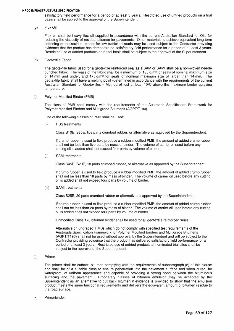
HRCC INFRASTRUCTURE SPECIFICATION
Page 69 of 127
satisfactory field performance for a period of at least 3 years. Restricted use of untried products on a trial basis shall be subject to the approval of the Superintendent.
(g) Flux Oil
Flux oil shall be heavy flux oil supplied in accordance with the current Australian Standard for Oils for reducing the viscosity of residual bitumen for pavements. Other materials to achieve equivalent long term softening of the residual binder for low trafficked roads may be used subject to the Contractor providing evidence that the product has demonstrated satisfactory field performance for a period of at least 3 years. Restricted use of untried products on a trial basis shall be subject to the approval of the Superintendent.
(h) Geotextile Fabric
The geotextile fabric used for a geotextile reinforced seal as a SAM or SAMI shall be a non-woven needle punched fabric. The mass of the fabric shall be a minimum of 135 g/m² for seals of nominal maximum size of 14 mm and under, and 175 g/m² for seals of nominal maximum size of larger than 14 mm. The geotextile fabric shall have a melting point (determined in accordance with the requirements of the current Australian Standard for Geotextiles – Method of test at least 10ºC above the maximum binder spraying temperature.
(i) Polymer Modified Binder (PMB)
The class of PMB shall comply with the requirements of the Austroads Specification Framework for Polymer Modified Binders and Multigrade Bitumens (AGPT/T190). One of the following classes of PMB shall be used:
(i) HSS treatments
Class S10E, S35E, five parts crumbed rubber, or alternative as approved by the Superintendent. If crumb rubber is used to field produce a rubber modified PMB, the amount of added crumb rubber shall not be less than five parts by mass of binder. The volume of carrier oil used before any cutting oil is added shall not exceed four parts by volume of binder.
(ii) SAM treatments Class S45R, S20E, 18 parts crumbed rubber, or alternative as approved by the Superintendent. If crumb rubber is used to field produce a rubber modified PMB, the amount of added crumb rubber shall not be less than 18 parts by mass of binder. The volume of carrier oil used before any cutting oil is added shall not exceed four parts by volume of binder.
(iii) SAMI treatments Class S25E, 20 parts crumbed rubber or alternative as approved by the Superintendent. If crumb rubber is used to field produce a rubber modified PMB, the amount of added crumb rubber shall not be less than 20 parts by mass of binder. The volume of carrier oil used before any cutting oil is added shall not exceed four parts by volume of binder. Unmodified Class 170 bitumen binder shall be used for all geotextile reinforced seals Alternative or ‘ungraded’ PMBs which do not comply with specified test requirements of the Austroads Specification Framework for Polymer Modified Binders and Multigrade Bitumens (AGPT/T190) shall not be used without approval by the Superintendent and will be subject to the Contractor providing evidence that the product has delivered satisfactory field performance for a period of at least 3 years. Restricted use of untried products at nominated trial sites shall be subject to the approval of the Superintendent.
(j) Primer
The primer shall be cutback bitumen complying with the requirements of subparagraph (e) of this clause and shall be of a suitable class to ensure penetration into the pavement surface and when cured, be waterproof, of uniform appearance and capable of providing a strong bond between the bituminous surfacing and the pavement. Proprietary classes of bitumen emulsion may be accepted by the Superintendent as an alternative to cut back bitumen if evidence is provided to show that the emulsion product meets the same functional requirements and delivers the equivalent amount of bitumen residue to the road surface.
(k) Primerbinder

HRCC INFRASTRUCTURE SPECIFICATION
Page 70 of 127
The primerbinder to be used shall be a cutback bitumen or a bitumen emulsion. The primerbinder shall be waterproof and capable of penetrating into and adhering to the pavement surface while retaining sufficient binder on the surface to hold the aggregate in place.
H17. AGGREGATE
(a) Aggregate Specification
Unless specified otherwise aggregate, including sands must comply with the following VicRoads Specifications:
801 - Source Rock for the Production of Crushed Rock and Aggregates
831 - Aggregate for Sprayed Bituminous Surfacing
832 - Sands for Sprayed Bituminous Surfacing.
(b) Aggregate Precoating
The Contractor shall either supply plant precoated aggregate from the aggregate supplier or field precoated aggregate from the stacksite.
H18. APPLICATION OF BITUMINOUS MATERIAL, AGGREGATE AND GEOTEXTILES
(a) Design Rates of Application
The Contractor shall determine the design rates of application for primer, primerbinder, binder, surface pre-treatments, remedial works and aggregate in accordance with the procedures set out in the current Update of the Austroads Sprayed Seal Design Method. All rates of application of bituminous material shall be expressed in litres/m². In the case of binder, rates of application shall refer to residual binder at 15°C. At least 1 week prior to the commencement of work, the Contractor shall submit the design rates of application for bituminous material, aggregate, and rates for pre-treatment for review by the Superintendent.
(b) Surface Pre-treatment Surface pre-treatments to correct variable surface texture shall be allowed for by the Contractor and carried out as part of the works to meet the requirements of Surface Texture and Aggregate Loss specified in Table 32 and Table 33. Where the Superintendent has included a requirement for pre-treatment, this does not limit the Contractor’s responsibility for pre-treatments on all jobs. The cost of surface pre-treatments shall be included in the lump sum works. The acceptance criteria for Surface Texture and Aggregate Loss specified in Table 32 and Table 33 will not be waived for any job item.
(c) Geotextiles
Geotextile reinforced seals shall be placed at a minimum pavement temperature of 20°C. Geotextile fabric shall be fixed to the pavement surface free of wrinkles and/or folds. This minimum temperature requirement shall not apply where the geotextile is placed as a Strain Alleviating Membrane Interlayer (SAMI) treatment underneath an asphalt wearing course. Transverse joins shall be butt jointed. Longitudinal joins in geotextile fabric shall be overlapped by approximately 150 mm and be located along lane lines. The Contractor shall make an allowance for additional binder to be applied along the join so that both geotextile layers are adequately saturated with bitumen. This allowance shall be included in the Contractor’s seal design. Unless otherwise specified, unmodified Class 170 bitumen binder shall be used for all geotextile reinforced seals.
H19. REMOVAL OF LOOSE AGGREGATE
The Contractor shall remove and dispose of all loose aggregate, within the maximum time limits as specified in Table 30 below. This includes loose aggregate on all trafficked areas, and areas where loose aggregate has been swept, or moved by traffic onto sealed shoulders or non-trafficked areas, or into other areas such as concrete channels, traffic islands, medians, open drains, drainage pits, footpaths, nature strips, or verges.

HRCC INFRASTRUCTURE SPECIFICATION
Page 71 of 127
Table 30 - Maximum Time Limit for Removal of Loose Aggregate
Traffic Volume (AADT) * Maximum Time Limit
>5000 and all Freeways Within 8 hours of sealing
>2000 to 5000 Within 24 hours of sealing
>500 to 2000 Within 48 hours of sealing
<500 Within 5 days of sealing
* Annual Average Daily Traffic - refer to Superintendent for AADT for each Job Item Until loose aggregate is removed from the sealed surface, traffic speed shall be controlled by signing and installation of road works speed limits in accordance with the VicRoads Work Site Traffic Management Code of Practice. Loose aggregate shall not be removed until the aggregate has properly bedded down into the binder by either trafficking or additional rolling. Any damage to the seal resulting from removal of loose aggregate shall be repaired by the Contractor. Rotary brooms and/or suction sweepers are permitted to remove loose aggregate from the trafficked areas unless otherwise directed by the Superintendent.
For seals of nominal size 10 mm and over, including multiple application seals:
After the removal of loose aggregate and at any time during the Defects Liability Period of the Contract, no more than 40 loose stones in any square metre of pavement shall remain. This includes stones that have originated from the area sealed under the Contract and which have accumulated on adjacent sealed areas such as intersections, additional traffic lanes (in either direction), shoulders, and flanks. On job items where 40 loose stones or more are measured warning signs shall be erected within eight hours, and the site shall be reswept, or the loose stones removed within 48 hours of measurement.
For seals of nominal size 7 mm and under:
After the removal of loose aggregate and at any time during the Defects Liability Period, no more than 60 loose stones in any square metre of pavement shall remain. This includes stones that have originated from the area sealed under the Contract and which have accumulated on adjacent sealed areas such as intersections, additional traffic lanes (in either direction), shoulders, and flanks. On job items where 60 loose stones or more are measured warning signs shall be erected within eight hours, and the site shall be reswept, or the loose stones removed within 48 hours of measurement.
H20. ACCEPTANCE OF WORK
(a) Rates of Application for Binder The Contractor shall produce evidence to show that the actual rate of application for a particular job, or segments of a job with different design rates of application, complies with the design rates of application. Variation between the actual rates and the design rates will be assessed in accordance with Table 31. If a payment deduction or rectification is required in respect of unsatisfactory surface texture or aggregate loss as specified in parts (b) and (c) of this clause, deductions under Table 31 will not be applied.

HRCC INFRASTRUCTURE SPECIFICATION
Page 72 of 127
Table 31 - Variation in Rates of Application of Bituminous Material
Variation from the Design Rates of Application for Bituminous Material (l/m²) *
Assessment
< 0.1 l/m² below the design rate of application Accept
> 0.1 l/m² to 0.2 l/m² below the design rate of application
Deduct $0.50/m² for the affected area provided that minimum texture and aggregate retention requirements are met
> 0.2 l/m² below the design rate of application Deduct $1.00/m² for the affected area provided that minimum texture and aggregate retention requirements are met
* The variation from the Design Rate of Application for SAM seals or SAMIs may be increased by 0.05 l/m². Acceptance or otherwise of the criteria specified in Table 31 shall not relieve the Contractor from its obligations under the Defects Liability Period.
(b) Surface Texture Acceptance of work for surface texture and surface enrichment shall be based on visual assessment, however in marginal cases the Superintendent may request that nominated areas be tested in accordance with VicRoads Test Method for Surface Texture of Sprayed Seals and assessed in accordance with Table 32. The test lot size shall not be less than 100 m of single traffic lane or more than 600 m of single traffic lane. For any testing undertaken on areas other than within traffic lanes, the minimum lot size shall be not less than 400 m² or more than 2500 m².
Table 32 - Test Requirements for Surface Texture
Treatment Mean Texture Depth (mm)
Action Required Size 5 Size 7 Size 10 Size 14
Seals (All Types)(1)
1.0 to 1.6 1.3 to 1.8 1.5 to 2.5 2.0 to 4.0 Accept
0.8 to 1.0 or
1.6 to 1.8
1.2 to 1.3 or
1.8 to 2.0
1.3 to 1.5 or
2.5 to 3.0
1.7 to 2.0 or
4.0 to 4.5
The Superintendent may require rectification of the works or elect to reduce payment for the lot by $1.00/m²
< 0.8 or
> 1.8
< 1.2 or
> 2.0
<1.3 or
> 3.0
< 1.7 or
> 4.5
Work to be rectified
Primerseals(2)
N/A 1.0 to 2.0 1.2 to 3.0 N/A Accept
N/A < 1.0 or
> 2.0
< 1.2 or
> 3.0
N/A Work to be rectified
Surface Enrichment(1)
N/A 0.8 Accept
N/A < 0.8 Work to be rectified
Notes: (1) Surface texture measurements for seals and surface enrichment may be undertaken at any time during the Defects Liability Period, but final acceptance of works is not affected until the end of the Defects Liability Period.
(2) Surface texture measurements for primerseals shall be undertaken no sooner than 10 weeks after placement, and no later than 15 weeks after placement. If tests are not undertaken in this period and later test results require the works to be rectified, the later test results are to be used for acceptance of the works.
(c) Aggregate Retention
Acceptance of work for aggregate retention shall be based on visual assessment however in marginal cases, the Superintendent may request that nominated areas be tested in accordance with the VicRoads Test Method for Stripping of Aggregate from Sprayed Seals and assessed in accordance with Table 33. Depending on the measured Degree of Aggregate Stripping, the Contractor shall take action as specified in Table 33. The test lot size shall not be less than 100 m of single traffic lane or more than 600 m of single traffic lane. For any testing undertaken on areas other than within traffic lanes, the minimum lot size shall be not less than 400 m
2 or more than 2500 m
2.
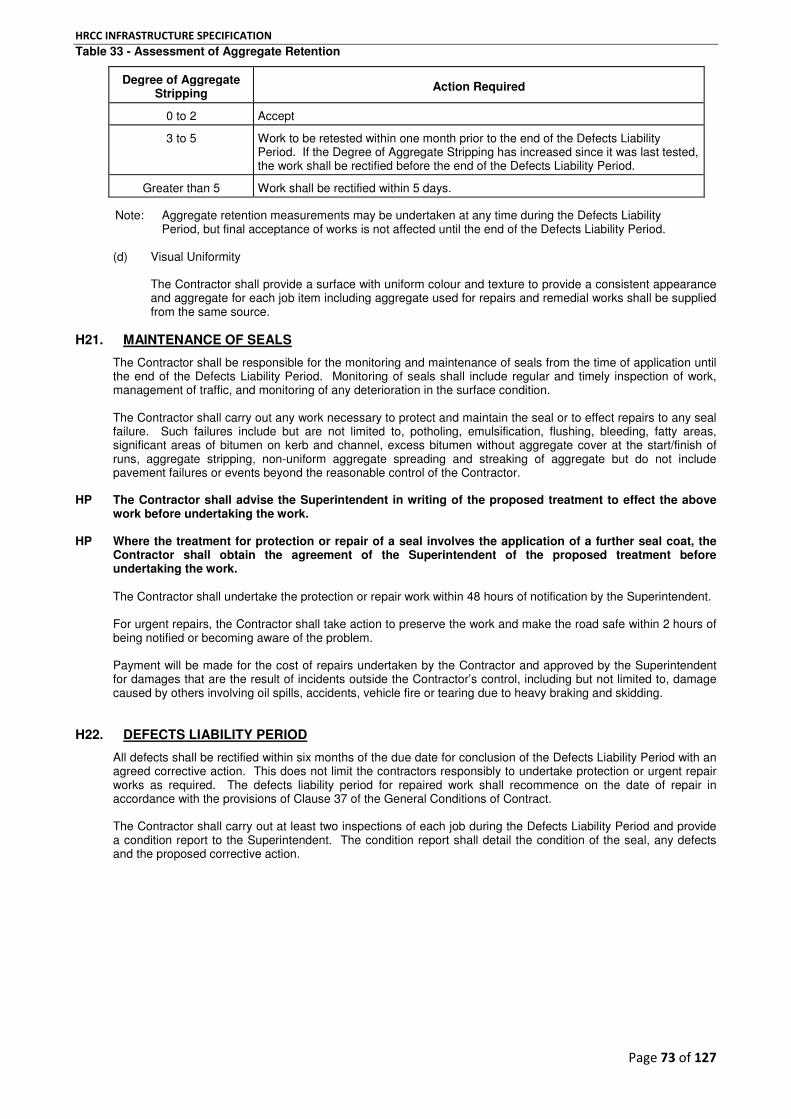
HRCC INFRASTRUCTURE SPECIFICATION
Page 73 of 127
Table 33 - Assessment of Aggregate Retention
Degree of Aggregate Stripping
Action Required
0 to 2 Accept
3 to 5 Work to be retested within one month prior to the end of the Defects Liability Period. If the Degree of Aggregate Stripping has increased since it was last tested, the work shall be rectified before the end of the Defects Liability Period.
Greater than 5 Work shall be rectified within 5 days.
Note: Aggregate retention measurements may be undertaken at any time during the Defects Liability Period, but final acceptance of works is not affected until the end of the Defects Liability Period.
(d) Visual Uniformity
The Contractor shall provide a surface with uniform colour and texture to provide a consistent appearance and aggregate for each job item including aggregate used for repairs and remedial works shall be supplied from the same source.
H21. MAINTENANCE OF SEALS
The Contractor shall be responsible for the monitoring and maintenance of seals from the time of application until the end of the Defects Liability Period. Monitoring of seals shall include regular and timely inspection of work, management of traffic, and monitoring of any deterioration in the surface condition. The Contractor shall carry out any work necessary to protect and maintain the seal or to effect repairs to any seal failure. Such failures include but are not limited to, potholing, emulsification, flushing, bleeding, fatty areas, significant areas of bitumen on kerb and channel, excess bitumen without aggregate cover at the start/finish of runs, aggregate stripping, non-uniform aggregate spreading and streaking of aggregate but do not include pavement failures or events beyond the reasonable control of the Contractor.
HP The Contractor shall advise the Superintendent in writing of the proposed treatment to effect the above work before undertaking the work.
HP Where the treatment for protection or repair of a seal involves the application of a further seal coat, the Contractor shall obtain the agreement of the Superintendent of the proposed treatment before undertaking the work. The Contractor shall undertake the protection or repair work within 48 hours of notification by the Superintendent. For urgent repairs, the Contractor shall take action to preserve the work and make the road safe within 2 hours of being notified or becoming aware of the problem. Payment will be made for the cost of repairs undertaken by the Contractor and approved by the Superintendent for damages that are the result of incidents outside the Contractor’s control, including but not limited to, damage caused by others involving oil spills, accidents, vehicle fire or tearing due to heavy braking and skidding.
H22. DEFECTS LIABILITY PERIOD
All defects shall be rectified within six months of the due date for conclusion of the Defects Liability Period with an agreed corrective action. This does not limit the contractors responsibly to undertake protection or urgent repair works as required. The defects liability period for repaired work shall recommence on the date of repair in accordance with the provisions of Clause 37 of the General Conditions of Contract. The Contractor shall carry out at least two inspections of each job during the Defects Liability Period and provide a condition report to the Superintendent. The condition report shall detail the condition of the seal, any defects and the proposed corrective action.
HRCC INFRASTRUCTURE SPECIFICATION
Page 74 of 127
PART I – ASPHALT
HOT MIX ASPHALT
I1. GENERAL
This section covers the requirements for the manufacture and placement of hot mix asphalt, including quality of materials, mix design, supply and placing of the asphalt.
I2. DEFINITIONS
Asphalt Base Course
Asphalt base course is that part of an asphalt pavement supporting the intermediate and wearing courses. It rests on the subgrade or pavement subbase.
Asphalt Course
An asphalt course comprises one or more layers of a single asphalt type.
Asphalt Intermediate Course
Asphalt intermediate course is that part of the asphalt pavement immediately under the wearing course. It rests on the asphalt base course.
Asphalt Layer
An asphalt layer comprises a single paving run of uniform asphalt.
Asphalt Pavement
Asphalt pavement comprises the combined thickness of all asphalt courses.
Asphalt Regulating Course
Asphalt regulating course is an asphalt course of variable thickness applied to the road surface to adjust the shape prior to the wearing course or any other bituminous surfacing or re-surfacing.
Asphalt Types (Dense Graded)
Dense graded asphalt types L, N, V and H series mixes primarily used for wearing and regulation courses, and Type S series mixes are primarily used as structural mixes for intermediate and base courses. A brief description for the various types of dense graded asphalt is shown in Table 34.

HRCC INFRASTRUCTURE SPECIFICATION
Page 75 of 127
Table 34 - Types of Dense Graded Asphalt
Mix Designation Description
L A light duty Size 7 or 10 wearing course with low air voids and higher binder content for use in very lightly trafficked pavements.
N A light to medium duty Size 7, 10 or 14 wearing course or regulating course for use in light to moderately trafficked pavements.
H A heavy duty Size 7, 10 or 14 asphalt wearing course or regulating course for use in most heavily trafficked pavements.
V A heavy duty Size 10 or 14 asphalt wearing course for heavily trafficked intersections.
HG A multipurpose heavy duty Size 10 or 14 wearing course asphalt incorporating multigrade binder where a high resistance to deformation is required, particularly at heavily trafficked intersections.
HP A high performance Size 10 or 14 heavy to very heavy duty wearing course asphalt incorporating a Polymer Modified Binder (PMB) where a high resistance to deformation and flexural cracking is required (formerly designated as Type Hm).
SI A multipurpose Size 14 or 20 structural asphalt for intermediate course in heavy duty pavements or base course in medium duty pavements (formerly designated as Asphalt Type T).
SF A fatigue resistant Size 20 structural base course asphalt for heavy duty asphalt pavements with a total asphalt thickness in excess of 175 mm (formerly designated as Asphalt Type R).
SP A high performance heavy to very heavy duty Size 20 structural intermediate course asphalt incorporating a Polymer Modified Binder (PMB) for high resistance to deformation and flexural cracking.
SG A multipurpose heavy duty Size 20 structural intermediate course asphalt incorporating a multigrade binder for high resistance to deformation particularly at very heavily trafficked intersections.
SS A very stiff Size 20 structural intermediate course asphalt sometimes used to increase pavement stiffness for very large scale heavy duty asphalt pavements (formerly designated as Type T600).
Asphalt Wearing Course
Asphalt wearing course is the final part of the pavement upon which the traffic travels except for Open Graded Asphalt (OGA) where the wearing course is the layer beneath the OGA.
Assigned Polished Stone Value
Assigned polished stone value is a friction rating derived from test results and is assigned to each source by VicRoads on the basis of past test data obtained from testing products.
Binder
Binder is bitumen, multigrade binder or polymer modified binder (PMB) used to hold a mixture of aggregates together as a cohesive mass.
Binder Film Index
Binder film index is an empirical calculation of theoretical thickness of the binder film around each aggregate particle within the asphalt mix having regard to the aggregate grading, surface area of the aggregates and binder content.
Bulk Density
Bulk density is the mass per unit volume of the compacted mix where the volume is the gross volume of the mix including the air voids.
Coarse Aggregates
Coarse aggregates are aggregates retained on a 4.75 mm AS sieve.
Cold Joints

HRCC INFRASTRUCTURE SPECIFICATION
Page 76 of 127
Cold joint are where asphalt is placed against the exposed edge of an existing asphalt mat, where the existing mat has cooled to less than 80˚C for bitumen and multigrade binders or to less than 100˚C in the case of PMBs.
Filler
Filler is that portion of the aggregates passing the 0.075 mm sieve. It includes the combined mass of crusher dust, any added recycled fines from asphalt plant dust extraction filters and any added filler required to enhance the mix properties.
Fine Aggregates
Fine aggregates are aggregates passing a 4.75 mm AS sieve.
Glass Fines
Glass fines are recycled glass cullet crushed to a cubic shape and passing the 4.75 mm AS sieve.
Hot Mix Asphalt (Asphalt)
Asphalt is a designed and controlled mixture of coarse and fine aggregates, filler and binder which is mixed, spread and compacted to a uniform layer while hot. Asphalt types are designated by the use of
symbols.
In situ Air Voids
In situ air voids represents the air voids in the field compacted mix on-site. It is based on a ratio of field density to maximum density.
Manufactured Sand
Manufactured sand is a material passing the 4.75 mm AS sieve produced by crushing igneous or metamorphic rock spalls or washed gravel.
Mineral Matter
Mineral matter includes coarse and fine aggregates, plus filler.
Placing
Placing is the spreading and compacting of asphalt, including operations necessary for preparation of the surface.
Reclaimed Asphalt Pavement (RAP)
Reclaimed asphalt pavement is asphalt removed from an existing asphalt pavement, and re-processed by crushing and/or screening for recycling into new asphalt.
Registered Mix
Registered mix is an asphalt mix which has been placed on the VicRoads Asphalt Mix Design Register.
Voids Free Bulk Density (VFBD)
Voids free bulk density is the maximum theoretical density of an asphalt mix if it were possible to compact it to zero air voids.
I3. AGGREGATES
(a) General
Aggregates shall consist of clean, hard, durable, angular rock fragments of uniform quality from a source approved by the Superintendent.
(b) Crushed Aggregate Products

HRCC INFRASTRUCTURE SPECIFICATION
Page 77 of 127
(i) The Flakiness Index of each separate sized coarse aggregate fraction, with a nominal size of 10 mm or larger, shall comply with Table 35.
(ii) The unsound and marginal rock in that fraction retained on a 4.75 mm AS sieve excluding any
RAP, shall not exceed the relevant percentages specified in Table 35.
Table 35 - Quality of Coarse Aggregates
Type of Asphalt Flakiness Index
(%) (max)
Total of Marginal and Unsound Rock
(% by mass) (max)
Unsound Rock (% by mass)
(max)
H and V Series 35 8 3
L, N, and S Series 35 10 5
(d) Crusher Fines and Manufactured Sand
Crusher fines and manufactured sand shall: (i) consist of a uniformly graded product of separate particles from the crushing of rock
appropriate to the asphalt type being produced; (ii) be free from lumps and aggregations; (iii) comply with the grading limits specified in Table 36.
Table 36 - Grading of Crusher Fines and Manufactured Sand
Sieve Size AS (mm)
Crusher Fines Percentage Passing
(by mass)
Manufactured Sand Percentage Passing
(by mass)
6.70 100 100
4.75 70 – 100 80 – 100
0.600 20 – 55 30 – 70
0.075 5 – 23 0 – 10
(iv) comply with the relevant requirements specified in Table 37.
Table 37 - Quality of Crusher Fines and Manufactured Sand
Test Value
Degradation Factor - Crusher Fines
(min)
Plasticity Index (max)
60 3
(e) Natural Sand
Natural sand extracted from natural sand deposits shall consist of clean, hard, durable grains free from lumps, clay, mica and organic or harmful matter. Where natural sand is accepted as washed sand for the registered mix, the Sand Equivalent Value of any such sand supplied for asphalt production shall not be not be less than 45. Where natural sand is accepted as unwashed sand for the registered mix, the Plasticity Index of any sand supplied for asphalt production shall not be more than 3.
(f) Glass Fines
Glass fines shall: (i) consist of a uniformly graded product with a maximum particle size of 5 mm, manufactured by
crushing of recycled glass cullet

HRCC INFRASTRUCTURE SPECIFICATION
Page 78 of 127
(ii) be generally free of contaminants such as paper, corks, metals, and other harmful materials
(maximum limit of 2% by mass). Glass cullet shall be primarily container glass and shall not include glass from ceramics, cathode ray tubes, fluorescent light fittings and laboratory glassware
(iii) comply with the grading limits specified in Table 36 for manufactured sand (iv) be cubical in shape, not sharp edged or elongated. The use of glass fines as a replacement for natural sands shall be limited to intermediate and base course layers.
(g) Aggregates for Asphalt Used as Wearing Course
(i) Coarse aggregates shall be a mixture of separate one-sized aggregates blended together. (ii) Coarse aggregates for Type, H, HG and HP asphalt shall have a minimum assigned Polished
Stone Value (PSV) of 48. Coarse aggregates for Type V asphalt shall have a minimum PSV of 54.
(iii) Fine aggregates shall be a mixture of one or more sands and crusher fines. For mixes designed by the Marshall method, the fraction passing the 4.75 mm AS sieve shall contain not less than 20% of natural sand. For wearing course mixes designed by the Austroads method using gyratory compaction, the quantity of natural sand may be less than 20%. No mix shall contain more than 65% by mass of natural sand.
(h) Aggregates for Asphalt Used as Intermediate or Base Course The combined aggregates shall consist either of crushed material or a mixture of crushed material and natural sands. The fraction of the mix passing the 4.75 mm AS sieve shall contain not more than 50% by mass of natural sands.
I4. FILLER
Mineral filler shall comply with the requirements of Table 38 and Table 39. If any of the following added fillers are specified or required, they shall comply with the corresponding requirements below: (a) hydrated lime complying with AS 1672 - Lime and limestones - Lime for building, and the requirements
of Table 39 (b) cement kiln dust complying with the requirements of Table 38 and Table 39 (c) ground limestone complying with the requirements of Table 38 and Table 39 (d) ground granulated blast furnace slag (GGBFS) complying with AS 3582.2 and the requirements of
Table 39 (e) portland cement complying with AS 3972 (f) fly ash produced from the combustion of black coal complying with Table 38 and Table 39.
Table 38 - Grading Limits (fillers other than Hydrated Lime, Cement and GGBFS)
AS Sieve Size (mm)
Percentage Passing by Mass
0.600 100
0.300 95 – 100
0.075 75 – 100

HRCC INFRASTRUCTURE SPECIFICATION
Page 79 of 127
Table 39 - Test Requirements for Filler
Filler Type Test Test Limit (%)
Total Combined Filler * Dry Compacted Voids 38 (Min)
All Added Fillers Moisture Content 3 (Max)
Cement Kiln Dust Water Soluble Fraction 20
Note on Table 41
* The total combined filler is the total amount of all filler in the mix including any added filler. I5. BITUMINOUS MATERIALS
(a) Binders
The class of binder for each asphalt type shall be as specified in Table 40.
Table 40 - Class of Binder
Asphalt Type Binder Class
L and N C170 or C320 *
H, V, SI and SF C320
HG and SG M500/170
HP and SP A10E ** PMB
SS C600
Notes on Table 42 * C170 Binder shall be used if the mix contains more than 10% RAP. ** PMB Class A10E shall be used unless otherwise specified. Classes 170, 320 and 600 bitumen used for production of asphalt shall comply with AS 2008 Residual bitumen for pavements. Bitumen used for Asphalt Types L, N, V and H shall comply with the additional requirement specified in Table 41.
Table 41 - Durability of Bitumen
Class of Bitumen
Durability * Minimum time to reach the specified apparent viscosity level (SAVL) days
170 9
320 7
Note on Table 43. * Test for resistance to hardening when exposed to heat and air. The viscosity of bitumen recovered from a sample of mixed asphalt prior to placement or from the roadbed after compaction, shall comply with the requirements specified in Table 42 and tested at the frequency specified in Table 46.

HRCC INFRASTRUCTURE SPECIFICATION
Page 80 of 127
Table 42 - Viscosity Range of Bitumen Recovered from Mixed Asphalt
Class of Bitumen
Viscosity Range at 25°°°°C kPa.s
Wearing Course
Intermediate Course
Base Course
170 200 - 600 200 - 1100 200 – 1600
320 500 - 1600 500 - 2300 500 – 3000
600 - 800 - 5500 800 – 5500
(b) Polymer Modified Binder (PMB) and Multigrade Binder All PMB and multigrade binders shall comply with the test requirements specified in the Austroads Specification Framework for Polymer Modified Binders and Multigrade Bitumens. The Contractor shall comply with the following requirements for supply and handling multigrade binder and PMB: (i) material shall be handled in accordance with the manufacturer's requirements (ii) a product quality certificate and test report from the manufacturer shall be obtained for each
delivery of material (iii) material shall be transported and stored in such a manner to avoid contamination and/or
deterioration of the product to the extent that it no longer complies with specified test properties.
(c) Bitumen Emulsion
Bitumen emulsion used for tack coating shall be a cationic rapid setting type complying with AS 1160, Bitumen emulsions for construction and maintenance of pavements. Emulsion diluted with water shall have a bitumen content of not less than 30%.
I6. MIX DESIGN
All asphalt mixes proposed for use on VicRoads works shall be registered in accordance with VicRoads Code of Practice RC500.01. All mix designs registered with VicRoads are issued a status according to compliance as: General Complies with the requirements of Code of Practice RC500.01. Non Standard Proprietary and other mixes that do not comply in all respects with the requirements of Code of Practice RC500.01 but where successful field trials have been undertaken for a period of at least three years and the mix performance continues to be closely monitored. Conditional Mixes which do not comply in all respects with the requirements of Code of Practice RC500.01 but which are considered appropriate for use subject to conditions attached to the registration. Experimental A mix that does not comply with the requirements of Code of Practice RC500.01 and for which there is little or no history of successful performance and requires more trials to be undertaken and monitored before it is registered as a Non Standard or Conditional mix. Superseded Superseded by another registered mix but details are retained for record purposes. Withdrawn Withdrawn from use because of unsatisfactory field performance but details are retained for record purposes.
HP No asphalt shall be supplied until the mix has been registered and the Superintendent approves the mix for use. The Contractor shall only use asphalt mixes that are registered by VicRoads as ‘General’ mixes. Approval of a registered mix for use under the Contract does not guarantee the handling properties or performance of the mix nor relieve the Contractor from contractual obligations in regards to rectification of defects. The Superintendent shall be notified of any proposed changes to the components or proportions of components used in the registered mix.

HRCC INFRASTRUCTURE SPECIFICATION
Page 81 of 127
New mix designs shall be carried out: where it is proposed to change the source grading or nature of the components or binders; and when current registered mix designs are more than two years old. If a registered mix has unsatisfactory handling or field performance, the Contractor or Superintendent may request the mix be de-registered in accordance with Code of Practice RC500.01.
I7. TOLERANCES ON MIX PRODUCTION
The production tolerances on the grading aim of the mix before compaction shall be as specified in Table 43. The tolerance on the binder content in the mix shall be ± 0.3% of the total mix by mass.
Table 43 - Production Tolerances for Mix Grading
Sieve Size AS (mm)
Tolerance on Percentage Passing (by mass)
Tolerance for Asphalt Types L, N, V, S and H series
(% by Mass)
Tolerance for Asphalt Type S
series (% by Mass)
Size 7 Size 10 Size 14 Size 20
37.5 Nil Nil Nil Nil
26.5 Nil Nil Nil Nil
19.0 Nil Nil Nil ±6
13.2 Nil Nil ±6 ±6
9.5 Nil ±6 ±6 ±6
6.70 - 4.75 ±6 ±6 ±6 ±6
2.36 - 0.600 ±5 ±5 ±5 ±5
0.300 - 0.150 ±3 ±3 ±3 ±3
0.075 ±1.0 ±1.0 ±1.0 ±1.0
Note on Table 44
If post compaction grading is checked by binder extraction and sieve analysis after placement, the positive tolerances shall be increased by one percentage point.
I8. PRODUCTION OF ASPHALT
(a) Temperatures
The temperature of binder and aggregates at the mixing plant and the temperature of the asphalt as it is discharged from the mixing plant shall not exceed the limits specified in Table 44. Asphalt manufactured at temperatures in excess of the limits specified in Table 44 shall not be used.
Table 44 - Maximum Mixing Temperatures
Material Temperature °°°°C
(max)
Binder plant storage 185 *
Aggregates before binder is added 200
Asphalt at discharge from mixing plant 175
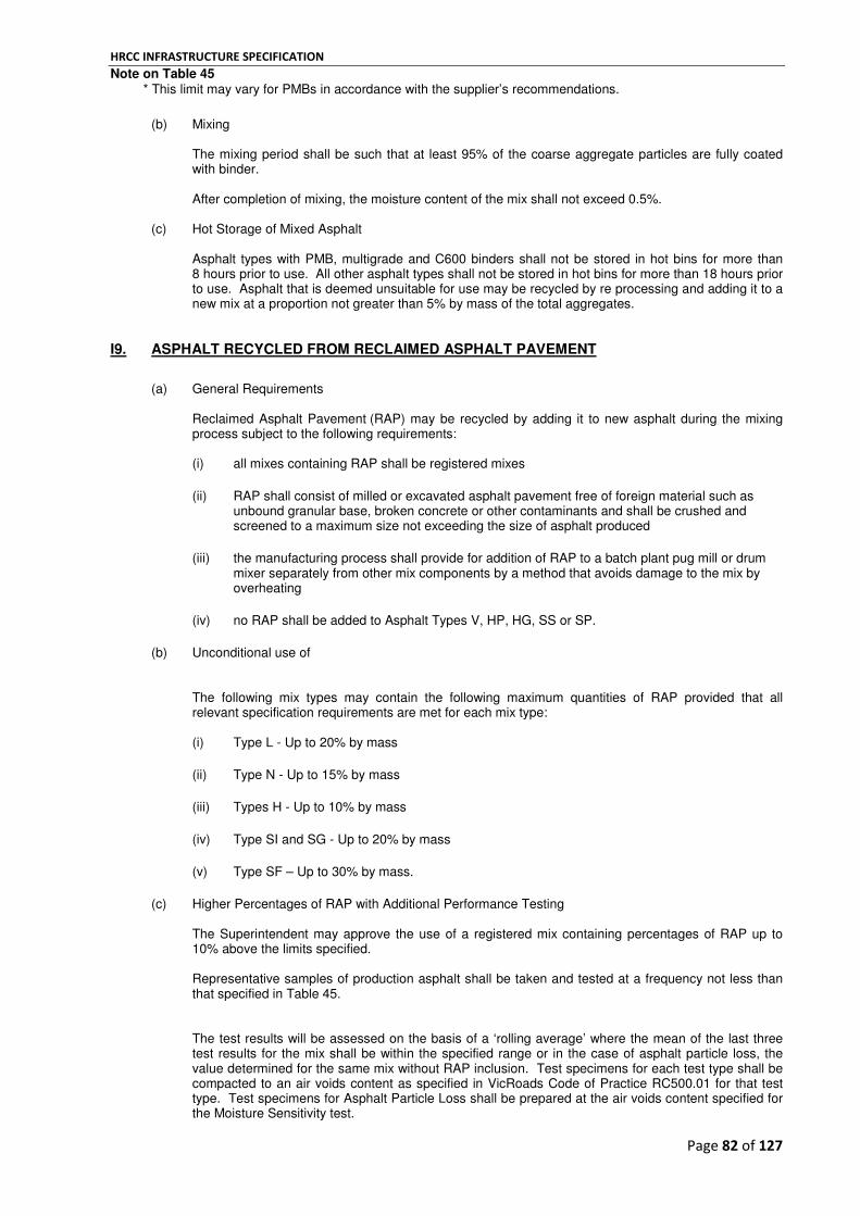
HRCC INFRASTRUCTURE SPECIFICATION
Page 82 of 127
Note on Table 45 * This limit may vary for PMBs in accordance with the supplier’s recommendations.
(b) Mixing The mixing period shall be such that at least 95% of the coarse aggregate particles are fully coated with binder. After completion of mixing, the moisture content of the mix shall not exceed 0.5%.
(c) Hot Storage of Mixed Asphalt
Asphalt types with PMB, multigrade and C600 binders shall not be stored in hot bins for more than 8 hours prior to use. All other asphalt types shall not be stored in hot bins for more than 18 hours prior to use. Asphalt that is deemed unsuitable for use may be recycled by re processing and adding it to a new mix at a proportion not greater than 5% by mass of the total aggregates.
I9. ASPHALT RECYCLED FROM RECLAIMED ASPHALT PAVEMENT
(a) General Requirements
Reclaimed Asphalt Pavement (RAP) may be recycled by adding it to new asphalt during the mixing process subject to the following requirements: (i) all mixes containing RAP shall be registered mixes
(ii) RAP shall consist of milled or excavated asphalt pavement free of foreign material such as unbound granular base, broken concrete or other contaminants and shall be crushed and screened to a maximum size not exceeding the size of asphalt produced
(iii) the manufacturing process shall provide for addition of RAP to a batch plant pug mill or drum mixer separately from other mix components by a method that avoids damage to the mix by overheating
(iv) no RAP shall be added to Asphalt Types V, HP, HG, SS or SP.
(b) Unconditional use of
The following mix types may contain the following maximum quantities of RAP provided that all relevant specification requirements are met for each mix type: (i) Type L - Up to 20% by mass
(ii) Type N - Up to 15% by mass
(iii) Types H - Up to 10% by mass
(iv) Type SI and SG - Up to 20% by mass
(v) Type SF – Up to 30% by mass.
(c) Higher Percentages of RAP with Additional Performance Testing The Superintendent may approve the use of a registered mix containing percentages of RAP up to 10% above the limits specified. Representative samples of production asphalt shall be taken and tested at a frequency not less than that specified in Table 45. The test results will be assessed on the basis of a ‘rolling average’ where the mean of the last three test results for the mix shall be within the specified range or in the case of asphalt particle loss, the value determined for the same mix without RAP inclusion. Test specimens for each test type shall be compacted to an air voids content as specified in VicRoads Code of Practice RC500.01 for that test type. Test specimens for Asphalt Particle Loss shall be prepared at the air voids content specified for the Moisture Sensitivity test.

HRCC INFRASTRUCTURE SPECIFICATION
Page 83 of 127
The results shall be presented in such a way that trends can be readily ascertained for each asphalt type so corrective action can be taken when required.
Table 45 - Frequency of Testing for Mixes with High Percentages of RAP
Check Required Minimum Frequency
Indirect Tensile Modulus In each production month - One per 2,000 tonnes or part thereof.
Moisture Sensitivity (Minimum Wet Strength and Tensile Strength Ratio)
In each production quarter – One per 10,000 tonnes or part thereof.
Mix Cohesion (Asphalt Particle Loss Test on moisture conditioned and unconditioned specimens)
In each production quarter – One per 10,000 tonnes or part thereof.
(d) RAP Stockpile Management Requirements
For the use of high RAP content asphalt mixes the asphalt manufacturer’s quality plan shall include a RAP stockpile management plan meeting the following requirements: • all RAP materials used for asphalt production shall be processed by blending, crushing and stockpiling • testing of the processed RAP stockpile to ensure uniformity of grading and binder content • ensure uniformity of the RAP stockpile properties by matching the registered asphalt mix design RAP gradings and bitumen content data with those RAP gradings and bitumen contents determined from multiple samples taken from the processed RAP stockpile • quality control testing of RAP stockpiles including a statistical assessment to measure variability of the product • once the processed RAP stockpile has been assessed for compliance there shall be no more processed RAP added to that stockpile • address issues such as contamination, mixing of various sources of RAP during processing, fractionating of the processed RAP, and storage or stockpiling of the compliant processed RAP in a manner that ensures materials removed are representative of the cross section of the processed RAP stockpile. During asphalt production, one sample shall be taken and tested for gradings and bitumen content from the processed RAP stockpile for every 1000 tonnes used.
I10. FREQUENCY OF INSPECTION AND TESTING AT THE MIXING PLANT
The frequency shall not be less than that shown in Table 46, except that the Superintendent may agree to a lower frequency where the Contractor has implemented a system of statistical process control and can demonstrate that such lower frequency is adequate to assure the quality of the product.

HRCC INFRASTRUCTURE SPECIFICATION
Page 84 of 127
Table 46 - Frequency of Inspection and Testing
Checks Required Minimum Frequency
Unsound rock content and particle size distribution of each aggregate and sand component including processed RAP
On each production day: One test on each component unless certification of specification compliance is received for each delivery to the mixing plant.
Degradation Factor of crusher fines At monthly intervals.
Plasticity Index of crusher fines and natural sand supplied as unwashed sand
At monthly intervals.
Sand Equivalent of natural sand supplied as washed sand
At monthly intervals.
Flakiness Index of coarse aggregate 10 mm and larger
At monthly intervals.
Viscosity of bitumen and multigrade binder at 60˚C
Certification of specification compliance for each delivery of bitumen supplied to the mixing plant.
At weekly intervals: where bitumen has been stored above 150˚C for more than 14 days without the storage tank being topped up by more than 50% of its capacity.
In cases where two or more bitumen classes are blended together to correct the viscosity, a viscosity test at 60˚C shall be taken prior to use and at weekly intervals thereafter.
Viscosity at 165˚, Torsional Recovery, and Softening Point of PMB
At weekly intervals: For PMB that has been stored above 165˚ for more than three days or between 140˚C and 165˚C for more than seven days without the storage tank being topped up by more than 50% of its capacity.
Scrutiny for segregation, uncoated particles, separated binder, excess binder or overheating before dispatch from the plant
Each loaded truck.
Temperature of asphalt before dispatch from the plant
Each loaded truck or at intervals of 15 minutes if more than one truck is dispatched in 15 minutes.
Binder Content and Full Sieve Analysis of Asphalt (full extraction test)
On each production day: One test per 250 tonnes or part thereof of the asphalt plant production on a representative sample taken from a delivery truck.
Moisture Content, Binder Content and Full Sieve Analysis of RAP (full extraction test)
At weekly intervals: One test on a representative sample of each 1,000 tonnes of RAP prior to use.
Viscosity of Recovered Bitumen at 25˚C As directed by the Superintendent – the average of three tests where asphalt Type V, H or Type SS is reasonably suspected of being over-heated or over-mixed.
The Contractor shall make available all completed work sheets, check lists and test reports for inspection at the mixing plant.
I11. RATE OF DELIVERY
Asphalt shall be placed at the highest practicable rate in order to minimise the time traffic is disrupted and to avoid intermittent paving.
I12. AMBIENT CONDITIONS FOR PLACING
The surface on which asphalt is to be placed shall be essentially dry and free from surface water.
(a) Intermediate and Base Courses Asphalt shall not be placed when the majority of the area to be paved has a surface temperature of less than 5°C. Asphalt mixes with PMB and Class 600 binder shall not be placed when the majority of area to be paved has a surface temperature less than 10°C.
(b) Wearing Course Wearing course asphalt shall not be placed when the majority of the area to be paved has a surface temperature of less than 10°C. Asphalt mixes with polymer modified binder shall not be placed when the majority of the area to be paved has a surface temperature less than 15°C.

HRCC INFRASTRUCTURE SPECIFICATION
Page 85 of 127
I13. SURFACE PREPARATION AND RAISING OR LOWERING OF MANHOLE AND VALVE COVERS
All manhole and valve covers shall be raised or lowered to the new surface level prior to asphalt work commencing. Temporary ramping around each cover shall be provided and removed prior to asphalt surfacing being placed. Prior to tack coating and placing of asphalt, the Contractor shall remove all harmful material and sweep clean the area upon which asphalt is to be placed.
I14. TACK COAT
A tack coat shall be applied to the cleaned asphalt or sealed surface on which asphalt is to be placed unless the unsealed surface has been primed. Tack coat shall consist of cationic bitumen emulsion and shall be applied only to a clean, essentially dry surface, free from surface water. Tack coat shall be sprayed in a uniform film over the entire road surface. The application rate for bitumen emulsion tack coat shall be 0.15 to 0.30 litres/m
2 (60% Bitumen content) or
0.30 to 0.60 litres/m2 (30% bitumen content), except for joints and chases where rates shall be doubled.
Before asphalt is placed, sufficient time shall be allowed for the free water to evaporate and for the tack coat to cure and change in colour from brown to black. Any tack coat not covered by asphalt shall be covered with clean grit or sand before the road is opened to traffic. Where asphalt is to be spread over clean, freshly laid asphalt, or over a clean, primed surface, or where the depth of the layer exceeds 50 mm, the Contractor may omit the tack coat.
I15. DELIVERY
(a) General Delivery shall only be made during the hours listed for possession of site. Asphalt delivered to the site, which is segregated, has been overheated, is too cold, contains separated binder or uncoated particles which does not comply with the Specification shall be removed from the site.
(b) Delivery Dockets
Delivery dockets shall show: (i) name of supplier and location of plant
(ii) docket number
(iii) name of user
(iv) project name and location (or contract number)
(v) registered number or fleet number of the vehicle
(vi) date and time of loading
(vii) size and type of asphalt
(viii) empty and loaded mass of the vehicle, or the total of the electronically measured batch weights printed on the docket
(ix) class of binder, and proprietary name of modified binder
(x) temperature of load at mixing plant when measured.
Where asphalt is scheduled for measurement by mass, a copy of the delivery docket for each load shall be provided at the point of delivery, or delivered to the Superintendent at the end of each day's work.

HRCC INFRASTRUCTURE SPECIFICATION
Page 86 of 127
Where asphalt is measured by other means and for Lump Sum Contracts, the Contractor shall make delivery dockets available for inspection on request by the Superintendent.
I16. JOINTS AND JUNCTIONS
(a) General The location of all joints shall be planned before work commences to achieve the specified offsets between layers and the final position of joints in the wearing course. The number of joints shall be minimised by adopting good asphalt paving practices. If requested by the Superintendent, the Contractor shall produce drawings showing the location of longitudinal joints of asphalt layers in respect to the traffic lane lines. All joints shall be well bonded and sealed and the surface across the joint. All cold joints and abutting concrete edges shall be heavily tack coated. Where cold joints are constructed, any loose or poorly compacted existing asphalt on the exposed edge shall be trimmed back to produce a face of fully compacted asphalt along the exposed edge before fresh asphalt is placed.
(b) Transverse Joints All transverse joints shall be offset from layer to layer by not less than 2 m.
(c) Longitudinal Joints
(i) Longitudinal joints in the wearing course shall coincide with the location of intended traffic lane lines.
(ii) Longitudinal joints in intermediate and base courses shall be offset from layer to layer by not less than 150 mm and shall be within 300 mm of the traffic lane line or the centre of traffic lane. Where new pavement abuts an existing pavement, the existing pavement shall be removed in steps to achieve an offset from layer to layer of not less than 150 mm.
(iii) Longitudinal joints shall be parallel to the traffic lanes.
(iv) Cold joints shall be avoided either by matching up all longitudinal joints over the full width of the carriageway each day or such lesser period depending on the rate of cooling of asphalt placed in the preceding run or by paving with two or more pavers in echelon.
Subject to approval by the Superintendent, a longitudinal joint in the wearing course may be located up to 300 mm from the traffic lane line, or 300 mm from the centre of a traffic lane.
(d) Junctions
At junctions where the new asphalt mat is required to match the level of existing pavement surface at the limits of work, chases shall be cut into the existing pavement by cold planing. The chase shall be cut by removal of a wedge of asphalt tapering from zero to a depth of 2.5 times the nominal size of the asphalt from the existing pavement to the minimum width as follows: • at side streets and median openings - 600 mm • on through carriageways with a speed limit of 80 km/h or less - 3 m • on through carriageways with a speed limit of more than 80 km/h - 6 m.
(e) Treatment of Exposed Edges under Traffic
On completion of each day's work and prior to opening to traffic, the following treatment of exposed edges shall be adopted for asphalt work.
(i) Longitudinal Edges
All longitudinal joints within the trafficked area shall be matched up between paver runs except for a short section required to achieve the minimum offset between transverse joints. Any exposed longitudinal edges within the trafficked area shall be ramped down at a slope of not steeper than 5 horizontal to 1 vertical by constructing a temporary wedge of hot mixed or cold mixed asphalt. In

HRCC INFRASTRUCTURE SPECIFICATION
Page 87 of 127
unusual situations such as the sudden onset of inclement weather, a longer length of longitudinal joint may be exposed provided it is ramped down as specified. (ii) Transverse Edges
At the end of the paving run in the transverse direction, the new asphalt mat shall be squared up to a straight line and ramped down by constructing a temporary wedge of hot mixed or cold mixed asphalt. Temporary ramping shall not be steeper than shown in Table 47.
Table 47 - Maximum Grade of Temporary Ramping
Posted Speed Limit (km/hr)
Maximum Ramp Grade (Horizontal to Vertical )
40 20 to 1
60 30 to 1
80 40 to 1
> 80 50 to 1
(iii) Removal of Temporary Ramping
Before commencement of each day's work, all temporary ramping shall be removed by cutting back along a straight line to expose a vertical face of fully compacted asphalt at the specified layer depth.
I17. COMMENCEMENT OF PLACING
HP The placement of asphalt on the sub-base or granular base for a new pavement or for an overlay of an
existing bituminous surfaced pavement shall not commence until approval to proceed is obtained from the Superintendent.
I18. REGULATING COURSE
A regulating course of asphalt of the type and size specified shall be placed for correction of longitudinal and transverse pavement shape so that the resulting surface is parallel with the finished surface. I19. SPREADING
(a) General Asphalt shall be spread in layers at the compacted thicknesses shown on the drawings or specified. All asphalt shall be spread with an asphalt paver except for small areas where use of a paver is not practicable.
(b) Level Control Asphalt paver screed levels shall be controlled by a suitable combination of manual and automatic controls operating from fixed or moving references.
(c) Spreading
All asphalt shall be spread with a purpose designed asphalt paving machine to form a uniformly smooth asphalt mat without segregation, tearing or gouging. The Contractor shall conduct spreading operations to ensure that the paver speed matches the rate of supply so that stoppages are minimised. If the paver is required to stop and asphalt in front of the screed cools to below 120˚C, a transverse joint shall be constructed. For asphalt work carried out on a road to be opened for traffic at the completion of work each day, each layer of asphalt shall cover the full width of the trafficked area. The requirements of Clause I16 shall be followed in respect of the treatment required for exposed edges.

HRCC INFRASTRUCTURE SPECIFICATION
Page 88 of 127
(d) Spreading by Hand
Hand spreading shall only be used for small areas where it is not practical to use a paver.
(e) Echelon Paving
Where specified, two pavers in echelon shall be used in locations where a full carriageway wider than 6 m is available clear of traffic. The width of a single paving run shall not exceed 6 metres unless paving in echelon is proposed.
(f) Trafficking of Type SF Asphalt
Trafficking or placement of asphalt over Type SF asphalt is not permitted unless the majority of the Type SF asphalt has a surface temperature of 50˚C or less and falling. Where trafficking of the Type SF results in deformation of the asphalt, further trafficking shall cease until such time that the Type SF asphalt has adequately cooled to allow works to proceed without further damage.
I20. COMPACTION
Asphalt shall be uniformly compacted as soon as the asphalt has cooled sufficiently to support the rollers without undue displacement.
I21. REQUIREMENTS FOR TESTING AND ACCEPTANCE OF COMPACTION
(a) General
Work shall be tested and accepted for compaction on either a test lot basis or on an approved procedural basis acceptable to the Superintendent. Where the total quantity of the particular size and/or type of asphalt supplied under the contract exceeds 300 tonnes, compaction shall be tested and accepted on a test lot basis. Acceptance of compaction for all other asphalt work will be on a procedural basis.
(b) Testing and Acceptance of Compaction on a Lot Basis
The density of extracted cores for the purposes of determining the bulk density for acceptance purposes or to check or assign offsets to a nuclear gauge shall be undertaken in accordance with VicRoads Codes of Practice 500.05 and 500.16. A lot presented for testing consists of that part of a particular layer of asphalt which is placed in one day under uniform conditions and is essentially homogeneous in respect to material and appearance. Sites for density testing shall be selected on an essentially random basis provided that no site shall be selected within 200 mm of a joint constructed against a cold edge. For core sample tests, the layer thickness is the mean thickness of the core samples and for nuclear gauge tests, the layer thickness is the nominal layer thickness. Asphalt Density Ratio is defined as the percentage ratio of the field bulk density to the assigned bulk density of the approved laboratory mix design. The Characteristic Value of Density Ratio is the calculated value of x - 0.92S for six tests per lot where x and S are respectively the mean and standard deviation of the individual density ratio test values for the lot. The work represented by a lot of six tests shall be assessed as shown in Table 48.

HRCC INFRASTRUCTURE SPECIFICATION
Page 89 of 127
Table 48 - Limits for Characteristic Density Ratio 9 (Six Tests)
For layers less than 50 mm thickness For layers 50 mm thickness or greater
Characteristic Value of the Density Ratio
(Rc) Assessment
Characteristic Value of the Density Ratio
(Rc) Assessment
94.0% or more Accept lot 96.0% or more Accept lot
91.0% to 93.9% Lot may be accepted at a reduced rate calculated by P = 10 Rc - 840
91.0% to 95.9% Lot may be accepted at a reduced rate calculated by P = 6 Rc - 476
(Rc) is the Characteristic Value of the density ratio for the lot and (P) is the percentage of the relevant scheduled rate to be paid which shall not be greater than 100%. Where the Contract is a lump sum Contract the relevant scheduled rate will be that shown in the ‘Rates for Variation Purposes’ schedule accompanying the lump sum tender. If no such rate is provided a variation will be considered in accordance with Clause 40.2 of the General Conditions of Contract - Valuation of Variations. Where one or more individual core thicknesses are less than the relevant values shown in Table 49, they shall be discarded and the acceptance assessment modified in accordance with Table 50 provided that there remain at least four test values.
Table 49 - Minimum Thickness of Cores Extracted from the Pavement
Size of Asphalt Individual Core Thickness (mm)
min
7 14
10 20
14 28
20 40
Table 50 - Mean Density Ratio (less than six cores)
For layers less than 50 mm thickness For layers 50 mm thickness or greater
Mean Value of the Density Ratio
(Rm) Assessment
Mean Value of the Density Ratio
(Rm) Assessment
95.5% or more Accept lot 97.0% or more Accept lot
92.5% to 95.4% Lot may be accepted at a reduced rate calculated by P = 10 Rm - 855
92.0% to 95.9% Lot may be accepted at a reduced rate calculated by P = 6 Rm - 482
(Rm) is the mean of the individual density ratios for the lot and (P) is the percentage of the relevant scheduled rate to be paid which shall not be greater than 100%. In situ Air Voids and Characteristic In situ Air Voids shall be reported for each lot. Percentage In situ Air Voids is defined as the ratio of In situ Air Voids to the Voids Free Bulk Density. Percentage In situ Air Voids represents the Air Voids of the compacted asphalt as placed onsite, and shall be determined as follows:

HRCC INFRASTRUCTURE SPECIFICATION
Page 90 of 127
In situ Air Voids = VFBD – field bulk density
x 100 VFBD
The Characteristic Value of In situ Air Voids is the calculated value of x + 0.92S for six tests per lot wherex and S are the mean and standard deviation of the individual In situ Air Void test values for the lot, respectively.
(c) Acceptance of Compaction on a Procedural Basis
Acceptance of work as far as compaction is concerned shall be based on the adoption of approved placing procedures and a density test check plan that provides for a minimum test frequency of 5% of relevant lots to be tested. The test check plan shall provide for additional testing to demonstrate correction of non-conformance. Placing procedures shall be in accordance with AS 2150 – Hot mix asphalt.
I22. SURFACE FINISH AND CONFORMITY WITH DRAWINGS
(a) General For all asphalt works the following requirements shall apply for conformance with location, shape, alignment, and width. (i) Surface Finish
The finished surface of asphalt wearing course shall be of uniform appearance, free of dragged areas, cracks, open textured patches and roller marks. (ii) Kerb and Channel
Where asphalt is placed against kerb and channel the surface at the edge of the wearing course shall be either flush with or not more than 5 mm above the lip of the channel.
(iii) Shape
No point on the finished surface of the wearing course shall lie more than 4 mm below a 3 m straight edge laid either parallel to the centreline of the pavement or, except on crowned sections, at right angles to the centreline. For intermediate and base course layers, the distance below the straight edge shall not exceed 6 mm and 10 mm respectively. (iv) Alignment
Where asphalt pavement is not +placed against a concrete edging, the edge of asphalt layers shall not be more than 50 mm inside nor more than 100 mm outside, the designed offset from centreline or design line. Within these tolerances, the rate of change of offset of the edge of layer shall not be greater than 25 mm in 10 m. (v) Width
Where asphalt pavement is not placed against a concrete edging, the width of asphalt layers shall not be less than the design or specified width of layer by more than 50 mm or greater than the design or specified width by more than 100 mm. The average width over any 300 m shall not be less than the design or specified width.
(b) Conformity with Drawings for New Pavements and Major Pavement Rehabilitation Projects
For pavement works where design drawings show the finished surface level and thickness of each pavement course, the surface level of each asphalt course shall be measured in accordance with the requirements of this specification. (i) Scale A and B Surface Level Requirements
Each level measurement shall be taken at random locations over the area of the lot in accordance with the relevant Test Method and the number of measurements taken within each lot shall not be less that the number specified in Table 51. The mean surface level and the variation in surface level for the base, intermediate and wearing courses within each lot shall meet the requirements of Table 52.

HRCC INFRASTRUCTURE SPECIFICATION
Page 91 of 127
Table 51 - Minimum Number of Level Measurements per Lot
Scale of Surface Level
Measurement
Minimum Number of Measurements Per Lot
Scale A 80
Scale B 40
Table 52 - Average Surface Level Tolerances for the Subbase and Pavement Courses
Scale of Surface Level
Measurement
Granular or Cement Treated Subbase
Asphalt Layers
Max. Range (mm)
Max. S (mm)
Max. Range (mm)
Max. S (mm)
Scale A +4 to –8 8 ± 5 8
Scale B +6 to -12 13 ± 8 10
Notes on Table 54.
x is the mean value of all level readings taken in the lot (a negative value designates a measured departure below the design level and positive value designates a surface level above the design level)
S is the standard deviation of all level readings taken in the lot.
For Scale A and Scale B level requirements, the Superintendent may agree to accept a lot which does not conform with the limits of Table 52 at a reduced payment, in accordance with Table 53.
Table 53 - Payment Deduction for Surface Level
Variation Payment reduction
Mean (x ) outside the specified limit up to a maximum of 25% of the limit.
8% plus 4% reduction for each 1 mm the mean value extends outside the tabulated limit
Standard Deviation (S) exceeding the specified limit up to a maximum of 35% of the limit.
8% plus 4% reduction for each 1 mm the Standard Deviation extends outside the tabulated limit
Note to Table 54. If both (x ) and (S) vary by more than the specified limit, the payment reduction shall be the sum of the
payment reductions for both (x ) and (S).
(ii) Scale C Surface Level and Thickness Requirements
The level of the top of each asphalt course shall not differ from the specified level by more than 15 mm for intermediate and base courses and 10 mm for wearing course. Where a uniform thickness of new asphalt pavement construction is specified, the mean thickness of a lot of asphalt shall be not less than the combined thickness of all asphalt courses specified or shown on the drawings. For the purpose of this clause, the maximum lot size shall be not more than 4,000 m
2 of pavement area.
(c) Asphalt Overlays
Where a minimum average or nominal thickness of overlay is specified, and no existing pavement or finished levels are available, the average thickness of the overlay shall be calculated by:
T = M
x 1000 D x A

HRCC INFRASTRUCTURE SPECIFICATION
Page 92 of 127
Where: T is the thickness of overlay in millimetres A is the area of the job in square metres D is the mean field density of placed asphalt in tonnes/m
3.
M is the mass of asphalt used in tonnes The average thickness of the overlay shall not be less than the specified thickness.

HRCC INFRASTRUCTURE SPECIFICATION
Page 93 of 127
PART J - SIGNAGE
SIGN INSTALLATION
J1. SCOPE
This section covers the installation of signs and sign supports that comply with: the VicRoads Traffic Engineering Manual Volume 2 - Signs and Markings; the VicRoads Manual of Standard Drawings for Road Signs; Australian Standard AS 1742 Manual of uniform traffic control devices and AS 1743 Road Signs – Specifications. Cantilever sign structures and sign gantries are outside of the scope of this document. Note: In general HRCC supplies & erect signage throughout the municipality for all its requirements, unless decided otherwise.
J2. SUPPLY OF MATERIALS AND COMPONENTS
All materials shall be supplied by the Contractor.
J3. TRANSPORT, HANDLING AND STORAGE OF SIGNS
The Contractor shall collect signs and sign components from the specified storage location and transport them to the specified sign location. Signs shall be transported, handled stored in a manner that prevents damage to and deterioration of sign components. If any damage or deterioration should occur to sign components, the Contractor shall repair or replace the affected item. Repairs shall restore the sign to the original condition using proprietary materials obtained from the sign manufacturer or alternative materials compatible with the original.
J4. CONFORMITY WITH DRAWINGS
The sign installation shall be as described in the sign schedule and as shown on the contract drawings. If the Contractor proposes to use an alternative method of installation, the Contractor shall submit full details not later than four weeks before the commencement of sign installation to the Superintendent for approval.
J5. TOLERANCES
(a) Foundations
The finished surface of concrete foundations shall be between 50 mm and 100 mm above the finished surface at the base of the sign and shall be shaped to ensure free drainage of water away from the base of the post.
(b) Posts
(i) shall be straight;
(ii) shall be vertical with a maximum deviation of 1 in 100;
(iii) post tops shall be 50 mm ± 10 below the top edge of the sign.
(c) Signs
(i) Signs shall be mounted level with a maximum deviation of 1 in 100.
(ii) Signs shall be mounted symmetrically on their posts unless the drawings indicate that an offset is required or if directed by the Superintendent.

HRCC INFRASTRUCTURE SPECIFICATION
Page 94 of 127
(iii) Where the sign comprises two or more signs above each other, the individual sign faces shall be mounted with the adjacent edges touching unless otherwise shown on the sign drawings.
(iv) Sign faces shall present an even surface free from twists, cracks, indentations or any other faults after erection.
J6. POSTS AND FOUNDATIONS
HP The required positions of all posts and signs shall be as directed by the Superintendent who shall confirm the positions before the erection of posts commences. Post details shall be as shown on the Sign and Post Schedule and in accordance with the contents of Chapter 6 of the Traffic Engineering Manual Volume 2. If the Contractor proposes the use of an alternative post and sign installation, full details of the proposals shall be supplied to the Superintendent for review not later than four weeks before installation. (a) Steel and Timber Posts
The Contractor shall conform to the requirements of Clause J4 and the Sign and Post Schedule. Where posts are to be mounted in sockets, the post shall be securely fixed into the socket by an approved vandal-proof method. Signs to be mounted on two or more posts shall have posts positioned such that the sign face is rotated away from the approaching traffic to avoid direct reflection. Posts shall be positioned such that the sign is rotated away from the cross section by an amount equal to one tenth of the width of the sign (approximately 5º). Posts specified as frangible hardwood shall be set at a level such that the centre of the lower hole of each post is 75 mm above the finished surface at the base of the post.
(b) Coatings for Sign Supports Steel posts shall be hot-dip galvanized in accordance with the Australian Standard for Hot-dip galvanized (zinc) coatings on fabricated ferrous articles. Sign supports shall be unpainted unless otherwise shown on the drawings. Any paints shall be in accordance with the relevant Australian Standard.
(c) Foundations All posts shall be set in concrete foundations to the depths shown in the Sign and Post Schedule and with the following hole diameters:
Foundation Hole Diameter
Post size and type (mm) Diameter (mm)
32 mm and 50 mm nominal bore steel 225
80 mm to 150 mm nominal bore steel 300
180mm x 100 mm frangible hardwood 300
Concrete used in foundations shall be 20 MPa at 7 days and 32 MPa at 28 days.
(d) Posts in Sockets If a sign is located in a paved area or in a location where the sign may be struck by a vehicle, e.g. at the end of an urban median or where it may be necessary to remove the sign to accommodate the swept path of over-dimensional vehicles, the post should be inserted into a socket cast into the ground. Suitable socket sizes for posts are as follows:

HRCC INFRASTRUCTURE SPECIFICATION
Page 95 of 127
Socket Size
Post size (mm) Socket Size (mm)
32 mm nominal bore tube 50 mm nominal bore tube
50 mm nominal bore tube 65 mm nominal bore tube
The depth of the socket should the same as the depth in ground nominated in Table 6.1 of the Traffic Engineering Manual Volume 2. The socket should protrude 50 mm above a soil surface or 25 mm above a paved surface. The sign post must penetrate a minimum 450 mm into the socket. The sign post should be securely fixed into the socket by an approved vandal-proof method. The sockets shall be plugged at the bottom and protrude between 20 mm and 30 mm above the finished surface of the concrete foundation.
(e) Backfilling of Post Holes
(i) 32 and 50 mm Nominal Bore Steel Posts
• posts holes shall be back-filled with concrete with a nominal strength of 10 MPa.
(ii) 180 mm x 100 mm Frangible Hardwood Timber Posts
• frangible Hardwood Posts shall be erected in accordance with the drawings; • post-holes for frangible hardwood posts shall be filled with a mixture of gravel and cement (4% by weight). (iii) Slip Base Strutted Aluminium Posts
• slip base strutted aluminium sign posts shall be erected in accordance with the drawings; • all foundations shall be 400 mm diameter and 1200 mm deep; • footing plates shall be set in concrete such that the top of the footing plate is between 50 mm and 125 mm above the finished surface at the base of the post or strut; • vertical posts shall be supplied cut to correct length and with post base and cap installed; • struts shall be supplied over-length with only the adjustable base installed; • the Contractor shall cut the strut to the correct length and install the strut-to-post clamp.
J7. INSTALLATION OF SIGNS
Installation of signs shall be in accordance with the Sign and Post Schedule. Fittings shall be appropriate to the size and type of sign and shall ensure that the sign face is securely connected to the post. (a) Signs shall be attached to the post(s) or structures using the type and number of fittings as specified in
the schedule or as follows:

HRCC INFRASTRUCTURE SPECIFICATION
Page 96 of 127
Size of Sign Number of Fittings per Post
Signs up to 200 mm in depth One
Signs 201 to 900 mm in depth Two
Signs 901 to 1200 mm in depth Three
One extra fitting shall be provided per post for each 400 mm increment or part thereof above 1200 mm.
(b) For braced signs, the sign shall be attached to the post at every intersection point between the sign bracing member and the post.
(c) Where a sign assembly consists of two or more signs, the signs shall be mounted in accordance with
the sign assembly drawings. (d) Signs shall be positioned in accordance with the following tolerances:
(i) ± 40 mm of the height specified in the Sign and Post Schedule measured from the bottom of the sign or sign assembly to the lip of the kerb or edge of shoulder nearest the sign;
(ii) ± 100 mm of the pegged sign location or specified location.
(e) When a sign is to be mounted on frangible posts on a cut batter having a slope steeper than or equal to 2:1, the mounting height at the shorter post may be reduced providing that:
(i) the uphill corner of the sign is a minimum of 800 mm above the ground;
(ii) the sign at the longer post is 2200 mm minimum above the ground.
(f) If required on the drawings sign faces shall be mounted on existing roadside poles, lighting columns, traffic signal pedestals. Where a sign is to be mounted with stainless steel straps, the brackets shall be attached to the pole using stainless steel straps of 12 mm minimum width and a minimum tensile strength 6.5 kN. Small signs with an area of not exceeding 0.3 m² shall be attached to steel or concrete electricity distribution poles, tramway poles, lighting columns and signal pedestals or mast arms by banding or other proprietary fittings. Signs exceeding 0.3 m² in area may be attached to existing poles (other than electricity distribution poles) provided that the pole has sufficient strength to support the additional loading due to the sign and that special joint-use supports are used. If the Contractor proposes to mount a sign on an existing pole, the strength of the pole and any other effects of mounting the sign in this way such as fatigue and durability shall be checked by an experienced structural engineer. Evidence of the structural checking shall be submitted to the Superintendent for review. The Contractor shall obtain permission shall for use of structures which are not VicRoads property. The maximum signboard areas which may be attached to joint-use structures are: • standard 114 mm OD signal pedestal - 1.0 m² • special 165 mm OD signal pedestals - 2.7 m² • joint use traffic signal/lighting column or traffic signal mast arm - 1.6 m² less the area of any traffic signal target boards facing in the same direction. Minimum lateral and vertical clearances adjacent and under the sign shall be maintained.
(g) Where the drawings indicate that a sign is to face oncoming traffic, it shall be mounted on posts which
have been rotated in accordance with the requirements of Clause J6(a), with the exception of signs mounted on structures over traffic lanes.
(h) Where signs are to be removed or relocated, as specified in the schedule, the Contractor shall
dismantle and transport the signs, posts and fittings to the specified new location or as directed by the Superintendent. Post holes shall be backfilled and compacted to the finished surface. Relocated signs shall be erected in their new position as specified.

HRCC INFRASTRUCTURE SPECIFICATION
Page 97 of 127
(i) After erection of each sign all stiffening bars are to be removed. (j) Single post mounting for large signs shall be provided if required on the drawings and the schedule.
Otherwise single post mountings shall be designed in accordance with Chapter 6 of the Traffic Engineering Manual Vol 2. Such supports are not to be made as breakaway supports.
(k) Installation of proprietary signs approved by VicRoads shall be in accordance with the supplier’s
recommendations as modified by VicRoads conditions of approval. J8. MASKING OF SIGNS
Where indicated in the schedule, the Contractor shall mask the nominated sign(s) by placing a porous cloth or similar covering that conceals the sign text under both wet and dry conditions and does not void the sign material warranty. The masking material shall be held in position by wire mesh over the sign. Adhesive material shall only be applied to the masking material and not be applied to either the front or rear face of the signboard. Signs marked ‘m’ in the Sign and Post Schedule shall be masked. The size of the masking material and its method of attachment shall be such that the sign is:
• effectively and securely covered; • wholly or partly covered, as required; • covered at all times and under all conditions.

HRCC INFRASTRUCTURE SPECIFICATION
Page 98 of 127
PART K - PAVEMENT MARKINGS AND DELINEATION
GUIDE POSTS K1. GENERAL
This specification sets out the requirements for the supply and installation of guide posts. Note: In general HRCC supplies & marks pavements throughout the municipality for all its requirements, unless decided otherwise.
K2. DEFINITIONS
Delineator Small retro reflective panel or sheeting attached to guide posts to provide a consistent pattern of delineation of the edges of road carriageways to aid road users during night time driving. Flexible Guide Post A guide post which deflects when impacted and then returns to a vertical position, without maintenance intervention. Guide Post Posts used to mark the edge of the road carriageway and give road users a good impression of the approaching alignment and geometry of the road. Rigid Guide Post A guide post which fractures or remains intact and straight, but not vertical when impacted. Semi-Flexible Guide Post A guide post which fails by bending when impacted and can be reinstated to vertical position with maintenance intervention.
K3. PRODUCT REQUIREMENTS
All guide posts including delineators installed in a section of road shall be uniform material and design. (a) General Requirements
Guide posts shall be between 90 mm and 100 mm across the face visible by traffic. The tops of guideposts shall be flat, the bottom ends made to suit the method of installation as recommended by the manufacturer. Guide posts shall be straight, smooth, structurally sound and of a shape that allows delineators to be permanently and securely attached. The above ground section of each guide post shall be free of sharp edges and burrs and discoloration or other defects that may affect its appearance and/or serviceability. The supplier shall state the type of material used in manufacture of the guide posts as well as recommended methods of installation, anchoring depth, cleaning, removal, and disposal. Test certification shall be submitted to the Superintendent for consideration, addressing post strength, flexibility, impact performance, durability, heat resistance, fire retardant ability, corrosion resistance and cold resistance. The supplier shall provide a performance guarantee statement clearly indicating the nature of the guarantee and the service life expectancy. Where a product is a VicRoads approved guide post product, or where directed by the Superintendant, the above shall not be required. All types of guideposts shall respond in a safe manner when struck, and not present a further danger in their damaged condition.
(b) Delineators The Contractor shall fix retro reflective type delineators to guide posts on both sides of the carriageway to expose to approaching traffic a red delineator on the left and a white delineator on the right. Delineators shall be either:

HRCC INFRASTRUCTURE SPECIFICATION
Page 99 of 127
(i) circular 80 mm diameter Type A corner cube retro reflectors conforming with Type ‘A’
delineator in AS 1906.2; or
(ii) Class 1A retro reflective sheeting having a total minimum reflective output equivalent to 100 cm2, as defined in AS/NZS 1906.1. The nominal dimension of retro reflective material shall be 50 mm x 200 mm. Delineators made from retro reflective sheeting shall be installed such that the sheeting manufacturer's preferred orientation for optimum performance is followed.
Delineators shall be placed centrally between the edges of posts, with the top of the delineator 50 mm below the top edge. Delineators shall be attached to posts following completion of final protective coatings by a vandal-proof and weatherproof means so they can be replaced if necessary without damaging the post.
(c) Markings To enable traceability of the manufacturer, each post shall be legibly and indelibly marked with the manufacturer’s name, date of manufacture and warranty period with lettering no greater than 10 mm high. The markings shall be placed at the bottom of the guide post just above recommended ground level installation depth. Guide posts shall be clearly marked to show the recommended ground level installation depth. Markings shall be installed on one side of the guide post only, and remain visible for the full life expectancy of the guide post.
K4. PERFORMANCE REQUIREMENTS
The finished surface of guide posts shall be uniform and free from discontinuities, areas of discoloration, blisters, runs and other surface defects which affect appearance and serviceability. Guide post surfaces shall be durable gloss or semi-gloss opaque white capable of being repeatedly cleaned. All materials used shall retain 85% of the original colour, appearance and physical properties and be resistant to ultraviolet radiation for at least ten (10) years when exposed to all weather conditions experienced in Victoria. Guide posts shall be designed to resist bending, twisting and displacement due to wind. They must be effective in resistance to vertical displacement of +5 mm for the life of the guidepost, with the exception of any displacement associated with impact or physical force. Flexible guide posts shall return to within +5 mm of the original vertical position following impact or physical force application for the life of the guide post.
K5. INSTALLATION
Installation of guide posts includes setting out, excavation, supply, placement, backfilling, erection, driving, removal and disposal of guide posts. Guide posts shall be installed in accordance with the requirements of Chapter 23 Traffic Engineering Manual Volume 2, as shown on the drawings, or as specified by the Superintendent. Guide posts shall be placed at a uniform distance from the road pavement edge with the widest face presenting to oncoming traffic. Posts shall be set into the ground so that the posts are vertical and the tops present a uniform profile. Guide posts shall be installed such that the exposed length above ground is nominally 1000 mm and minimum anchoring depths recommended by the manufacturer to achieve the specified performance requirements under service conditions. Allowance shall be made in the height of guide posts above the ground for the effects of superelevation and other road geometry in order to keep guide posts within the range of the beam of vehicle headlights. Guideposts shall be installed as per the manufacturer’s recommendation. Where guide posts are to be set in the ground they shall be erected in excavated holes which are subsequently backfilled and compacted to a density that is not less than that of the adjacent undisturbed ground. Guide posts shall be installed such that they effectively resist removal by persons other than personnel using recommended removal tools. Where guide posts are to be installed directly onto concrete, asphalt of any other hard wearing surface, the Contractor shall submit to the Superintendent the details of the proposed installation method. (a) Wire Rope Safety Barrier Installations
Where new installations of Wire Rope Safety Barrier (WRSB) are proposed on the edge of shoulder, and will conflict with guide post installation locations, WRSB posts shall be converted into guide posts

HRCC INFRASTRUCTURE SPECIFICATION
Page 100 of 127
in accordance with the above product requirements. Posts shall be spaced in accordance with the Drawings or the requirements of Chapter 23 Traffic Engineering Manual Volume 2. The Contractor shall submit to the Superintendent the details of the proposed installation.
(b) Underground Services Underground service locations shall be determined prior to installation of posts.
(c) Tolerances
Maximum installation tolerances are as follows: (i) within 3 degrees of true vertical position
(ii) within +5 mm across the face visible by traffic
(iii) within +50 mm of the uniform profile height (nominally 1000 mm)
(iv) within 200 mm longitudinally of the design spacing requirement and 100 mm transversely of the plan position with reference to the design line for the road, or as per the requirements of Chapter 23 Traffic Engineering Manual Volume 2.
(d) Removal and Disposal of Existing Guideposts Existing guide posts where required, are to be removed as directed by the Superintendent. All holes left after removal shall be backfilled and compacted to a density that is not less than that of the adjacent undisturbed ground, or the same characteristics of the shoulder material from where they were removed. All existing guide posts removed by the Contractor shall be disposed of off site or as directed by the Superintendent. Existing guideposts manufactured from recyclable materials shall be recycled.
FIXING RAISED PAVEMENT MARKERS
K6. DESCRIPTION
This section covers the fixing of both reflective and non-reflective raised pavement markers to asphalt, concrete or sealed pavements using epoxy adhesive or hot melt bitumen adhesive.
K7. TOLERANCES ON POSITION
Markers shall be affixed to the pavement at the positions shown on the drawings, or specified or directed by the Superintendent within the following limits, unless otherwise specified.
(a) Markers in Line with Broken Line Segments
Transverse position within 25 mm of the centreline of the segments. Longitudinal position within 0.5 m of the specified position.
(b) Markers in a Longitudinal Group
Transverse position of the centre of each marker within 25 mm of the specified position and within 10 mm of a line joining the centres of the end markers of the group. Longitudinal position of the end markers of the group within 0.5 m of the specified position. Spacing of markers within the group within 50 mm of the specified spacing.
(c) Markers Adjacent to Unbroken Line
Clearance to edge of line within 5 mm of that specified. Longitudinal mismatch between markers in transverse pairs at barrier line not more than 25 mm. Longitudinal position of markers within 0.5 m or 10% of the specified spacing, whichever is the less.
(d) Orientation of Reflective Markers

HRCC INFRASTRUCTURE SPECIFICATION
Page 101 of 127
Lower edge of the reflective face at 85° to 95° to the centreline of the roadway or any adjacent line.
K8. MATERIALS
The Contractor shall supply all materials required to complete the work covered by this section, unless otherwise specified. (a) Markers
Markers shall comply with the relevant requirements of AS 1906, Part 3. Only markers approved for use by the Superintendent shall be used and all raised non-reflective pavement markers shall be of the ultra hard plastic type unless otherwise directed.
(b) Adhesive
Epoxy adhesive shall be Standard Set or Rapid Set adhesive complying with the relevant requirements of AS 3554. Only adhesives approved for use by the Superintendent shall be used.
K9. MIXING EPOXY ADHESIVE
Adhesive components shall be batched so that the mixed adhesive contains not less than 45% nor more than 55% by volume of either component. Before starting work each day, or when changing to a different batch of adhesive, a hand-mixed colour standard shall be prepared for reference during the day. When machine mixing is used the mixing equipment shall use positive displacement pumps which proportion the two components in the specified range. At the beginning of each day and at any other time ordered by the Superintendent, the Contractor shall check the proportions in the presence of the Superintendent. Adhesive which has remained in the mixing head for longer than 90 seconds for rapid set adhesive or 180 seconds for standard set adhesive shall be discharged to waste. When hand-mixing is used not more than 500 g of each component shall be mixed at any time. The components shall be mixed on a flat surface and the mixed adhesive shall be used within 10 minutes of the time the two components are brought together. Only standard set adhesive shall be mixed by hand, unless the Superintendent consents otherwise.
K10. PREPARING HOT MELT ADHESIVE
Hot melt bitumen adhesive shall not be used on days of total fire ban without the written approval of the Country Fire Authority. Two nine kilogram Dry Powder extinguishers and one knapsack sprayer shall be carried at all times. The hot melt bitumen adhesive shall be heated in accordance with the manufacturer's specification in a heater designed specifically for the purpose. It shall be regularly stirred in the heater during the laying operation to maintain uniformity of the component proportions.
K11. PAVEMENT PREPARATION
The Contractor shall sweep or air blast each marker site as necessary to remove loose material before placing markers. Markers shall only be placed at locations where the pavement is free from dirt, oil, grease, paint, or any other material which would adversely affect the bond of the adhesive to the pavement, unless otherwise specified.
K12. PLACING MARKERS
Markers shall not be placed in any of the following circumstances: when the pavement is wet; when the relative humidity is greater than 80%; when the ambient temperature or the temperature of the road surface is less than 15°C for standard set adhesive or 0°C for rapid set or hot melt adhesive.
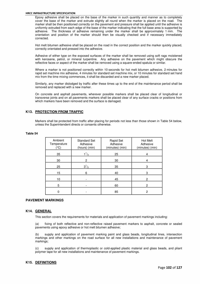
HRCC INFRASTRUCTURE SPECIFICATION
Page 102 of 127
Epoxy adhesive shall be placed on the base of the marker in such quantity and manner as to completely cover the base of the marker and extrude slightly all round when the marker is placed on the road. The marker shall be then positioned correctly on the pavement and pressure shall be applied until the adhesive is uniformly extruded from each edge of the base of the marker indicating that the full base area is supported by adhesive. The thickness of adhesive remaining under the marker shall be approximately 1 mm. The orientation and position of the marker should then be visually checked and if necessary immediately corrected. Hot melt bitumen adhesive shall be placed on the road in the correct position and the marker quickly placed, correctly orientated and pressed into the adhesive. Adhesive of either type on the exposed surfaces of the marker shall be removed using soft rags moistened with kerosene, petrol, or mineral turpentine. Any adhesive on the pavement which might obscure the reflective faces or aspect of the marker shall be removed using a square-ended spatula or similar. Where a marker is not positioned correctly within 10 seconds for hot melt bitumen adhesive, 2 minutes for rapid set machine mix adhesive, 4 minutes for standard set machine mix, or 10 minutes for standard set hand mix from the time mixing commences, it shall be discarded and a new marker placed. Similarly, any marker dislodged by traffic after these times up to the end of the maintenance period shall be removed and replaced with a new marker. On concrete and asphalt pavements, wherever possible markers shall be placed clear of longitudinal or transverse joints and on all pavements markers shall be placed clear of any surface cracks or positions from which markers have been removed and the surface is damaged.
K13. PROTECTION FROM TRAFFIC
Markers shall be protected from traffic after placing for periods not less than those shown in Table 54 below, unless the Superintendent directs or consents otherwise.
Table 54
Ambient Temperature
(°C)
Standard Set Adhesive
(hours) (min)
Rapid Set Adhesive
(minutes) (min)
Hot Melt Adhesive
(minutes) (min)
35
1
1/4
25
4
30
2
30
4
25
3
1/2
35
3
15
6
40
3
10
-
45
2
5
-
60
2
0
-
85
2
PAVEMENT MARKINGS K14. GENERAL
This section covers the requirements for materials and application of pavement markings including: (a) fixing of both reflective and non-reflective raised pavement markers to asphalt, concrete or sealed pavements using epoxy adhesive or hot melt bitumen adhesive; (b) supply and application of pavement marking paint and glass beads, longitudinal lines, intersection markings and other markings on the road surface for all new installations and maintenance of pavement markings; (c) supply and application of thermoplastic or cold-applied plastic material and glass beads, and pliant polymer tape for all new installations and maintenance of pavement markings.
K15. DEFINITIONS

HRCC INFRASTRUCTURE SPECIFICATION
Page 103 of 127
Pavement Marking The term used to define all linemarking, roadmarking and raised pavement markers
Linemarking The term used to define all longitudinal lines such as centre, lane, edge, turn and continuity lines.
Roadmarking The term used to define all transverse lines and markings applied by hand such as Stop/Give Way lines, pedestrian lines, arrows, and legends.
Maintenance of Pavement Markings Refers to the refreshing or replacement of an already existing pavement marking.
New Pavement Markings Refers to applying pavement markings to a new surface where no pavement marking exists i.e. after reseals, asphalt resurfacing, newly constructed pavements, major projects, and modifications to existing pavement markings.
Raised Pavement Marker A device placed on a pavement which may be a: Non Reflective Marker A device to provide a degree of delineation during daylight owing to the contrasting colour, reflection and profile with respect to the pavement surface. Also a device which reflects ambient light during the day-time and to a limited degree when illuminated at night.
Reflective Marker A device which produces an effective point source of light at normal highway viewing distances by reflecting incident light in directions close to the direction from which it came. Also a device to provide a degree of delineation during daylight owing to the contrasting colour, reflection and profile with respect to the pavement surface.
Temporary Reflective Marker A temporary device performing the same function as a Reflective Marker but with an intended life of not more than two weeks under average traffic conditions.
Retroreflectivity A property of some materials, such as solid glass beads, to reflect incident light in directions close to the direction from which it came. Retroreflectivity is the value of reflected light measured in millicandella / lux / square metre and is used as a measure of light reflected by pavement markings.
Retroreflectometer A device used to measure retroreflectivity. For the purpose of this contract the geometry of the retroreflectometer shall be based on 30 m observation geometry.
Urban Area An area in which: (a) a speed limit of 60 kilometres per hour or less applies and is not a speed limit which applies only because of a temporary reason such as roadworks or a street event; or (b) there are buildings on land next to the road or where the street lighting poles are not more than 100 m apart for -
(i) a distance of at least 500 m; or
(ii) if the length of the road is less than 500 m, over the full length of the road.
Rural Area An area that is not an Urban Area.
K16. STANDARDS
The dimensions and colour of pavement markings shall conform to the following standards:
(a) VicRoads Traffic Engineering Manual, Volume 2 ; (b) the linemarking drawings included in Section 5 Supporting Documents Plans and Drawings:.

HRCC INFRASTRUCTURE SPECIFICATION
Page 104 of 127
Paint and long life material shall be white, except in snow areas and Fairway tramline markings which shall be yellow or as otherwise specified or required in Traffic Engineering Manual, Volume 2.
K17. SCOPE OF WORK
The scope of work includes the supply of all materials and placement of pavement markings in accordance with this specification. (a) New Pavement Markings
For new pavement marking the following works shall be undertaken as part of the works and in accordance with this section K: (i) immediately prior to resurfacing, removal of any existing reflective and non reflective markers
(ii) placement of temporary reflective pavement markers including removal of protective covers after surfacing works
(iii) initial placement of pavement markings, including reinstatement of any adjoining pavement markings blackened but not necessarily covered by the surfacing activity, comprising -
reinstatement and/or placement of raised pavement markers and removal of temporary raised reflective pavement markers temporary replacement of profiled lines with painted lines reinstatement and/or placement of other long life pavement markings reinstatement and/or placement of painted pavement markings (iv) second coat of painted pavement markings, including temporarily replaced lines
(v) reinstatement of profiled lines temporarily replaced with paint.
(b) Maintenance of Pavement Markings Maintenance works shall entail preparing the site and refreshing the existing pavement markings with the same material as the existing markings in accordance with this specification.
K18. LIMIT OF WORK
(a) For new pavement markings the limit of pavement marking works shall be the same as the limit of the new surfacing or as shown in Section 5 Supporting Documents Plans and Drawings. (b) For the maintenance of existing pavement markings the works shall include all existing tapers, bell mouths at intersecting roads, pavement widening and traffic lanes. The limits of work at typical intersections are shown in Section 5 Supporting Documents Plans and Drawings.
K19. INCLUSION AND DELETION OF JOB ITEMS
(a) The Superintendent may delete any work, subject to notice of deletion being given one month prior to the proposed programmed date. The Contractor will be notified in writing of such deletion and the contract sum adjusted by the price tendered in Schedule 1 for the job item(s) deleted. (b) No additional payment will be made as a result of the deletion of any work or job item. However, where the deletion of job items results in a contract sum reduction of more than 20 per cent of the original contract sum, the deletion of job items in excess of this amount will be treated as a variation under Clause 40 of the General Conditions of Contract. (c) The Superintendent may request the Contractor to undertake additional pavement marking works at nominated sites. These works will be treated as a variation under Clause 40 of the General Conditions of Contract, except that the work shall be valued using Schedule 2 – Rates for Variation Purposes.
K20. EXCLUSION OF ROADWORKS
For works involving the maintenance of pavement markings, the Contractor will not be responsible for maintaining pavement markings unless otherwise directed by the Superintendent where it is evident that roadworks are taking place or will shortly take place which will interfere with the installation of the markings or which will damage the completed markings.

HRCC INFRASTRUCTURE SPECIFICATION
Page 105 of 127
The Contractor shall record the location of any road lengths not maintained and notify the Superintendent of the locations at least 24 hours prior to the pavement marking work being undertaken adjacent to the road lengths.
K21. MATERIALS
Pavement marking materials shall conform to the following standards. (a) Linemarking and Roadmarking Paint
All paints shall be approved under the Australian Paint Approval Scheme (APAS). In addition: (i) Initial Markings
For initial marking on reseals and other new surfaces, paint shall comply with the requirements of AS 4049.1 for solvent-borne paint or AS/NZS 4049.3 for water-borne paint .
(ii) Temporary Markings
For temporary markings, paint shall comply with the requirements of AS 4049.1 for solvent-borne paint or AS/NZS 4049.3 for water-borne paint or other material as approved by the Superintendent.
(b) Glass Beads
(i) Glass beads shall be used on all applications of material and for all pavement markings and shall conform to the requirements in AS/NZS 2009 and the Australian Paint Approval Scheme (APAS) Specification 0042.
(ii) Intermix glass beads for use in long life material applications shall conform to AS/NZS 2009 and the Australian Paint Approval Scheme (APAS) Specification 0042.
(iii) The amount of heavy metals in the beads shall not be greater than that specified in APAS Specification 0042.
(c) Thermoplastic Pavement Marking Material
Thermoplastic pavement marking material used under this Contract shall comply with the requirements of AS 4049.2. Thermoplastic pavement marking material intended for use under this Contract to provide profiled lining shall provide a functional service life of at least six years. The material shall, as a minimum, comply with the requirements of AS 4049.2.
(d) Cold-applied Plastic Pavement Marking Material Cold-applied plastic pavement marking material used under this Contract shall be a Poly Methyl Methacrylate resin based pavement marking material conforming with the colour, luminance and bead content requirements of AS 4049.2.
(e) Pliant Polymer Pavement Marking Tape
Pliant polymer pavement marking tape intended for use under this Contract shall be approved by the Superintendent.
K22. PROGRAM
(a) For new pavement markings the Contractor shall undertake pavement marking works in accordance with the following requirements.
(i) After Resurfacing Works
The initial coat of paint, long life pavement markings (other than profiled linemarking) and raised pavement markers (reflective and non-reflective) on newly surfaced pavements shall be installed in accordance with the following timeframes: AADT ≥5,000 within 24 hours of opening to traffic AADT ≥1,000 and ≤4,999 within 3 days of opening to traffic

HRCC INFRASTRUCTURE SPECIFICATION
Page 106 of 127
AADT < 1000 within 5 days of opening to traffic (ii) The Contractor shall apply the second/final coat of painted pavement markings not less than
four weeks and not more than eight weeks after the initial paint treatment.
(iii) Profiled lines shall be reinstated no earlier than four weeks and no longer than eight weeks following the application of the painted temporary line.
(iv) For new works constructed clear of traffic, all pavement markings shall be completed prior to opening to traffic.
K23. REMOVAL OF PAVEMENT MARKINGS
Where required the Contractor shall remove existing pavement markings to the standard approved by the Superintendent and appropriate to the marking being removed.
K24. LAYOUT OF MARKINGS
The Contractor shall be responsible for the layout of and spotting out for markings in accordance with the VicRoads Traffic Engineering Manual Volume 2.
K25. POSITION OF MARKINGS
Pavement markings shall be positioned in accordance with the following requirements. (a) New pavement markings shall be:
(i) set out by the Contractor in conformance with the appropriate standard
(ii) applied within the tolerances specified in Clause K26.
(b) Maintenance Pavement Markings shall be:
(i) reinstated by the Contractor at locations where the existing markings are badly worn, out of standard, or are missing altogether. The Contractor shall reinstate the marking in conformance with the appropriate standard.
(ii) applied within the tolerances specified in Clause K26.
K26. TOLERANCES ON PAVEMENT MARKINGS
(a) New Pavement Markings
The Contractor shall install new painted and long life pavement markings so that the: (i) distance between the centreline of the marking and the centreline of the set out mark is less
than 30 mm
(ii) apparent line of the markings is a smooth, continuous alignment when viewed in the direction of the line
(iii) width of completed markings is within ±10 mm of the specified dimensions, except long life materials where the tolerance is -0 mm to +10 mm
(iv) length of completed stripes and blocks is within - 0% to +10% of the specified length
(v) gap between double lines is within -10 mm to +0 mm of the required 100 mm gap
(vi) paint, long life material and bead application rates are within -0% to +50% of the specified rate.
(b) Maintenance of Pavement Markings The Contractor shall maintain painted and long life pavement markings so that the:

HRCC INFRASTRUCTURE SPECIFICATION
Page 107 of 127
(i) distance between the centreline of the completed marking and the centreline of the previous marking is less than 15 mm
(ii) apparent line of the completed markings is a smooth, continuous alignment when viewed in the direction of the line
(iii) width of completed markings is within ±10 mm of the specified dimensions, except long life materials where the tolerance is -0 mm to +10 mm
(iv) previously applied markings that are visible which have a total width equal to or exceeding the standard width plus the above tolerances, application of the maintenance marking shall not increase the total width of all applications
(v) length of completed stripes and blocks is within -0% to +10% of the specified length
(vi) position of either the start or finish of a completed stripe or block is less than 5% of the specified length of the stripe or block beyond the start or before the finish of the existing stripe or block respectively
(vii) paint and glass bead application rate is within -0% to +50% of the specified rate
(viii) gap between double lines is within -10 mm to +0 mm of the required 100 mm gap or if the gap between the existing lines is 90 mm or less the gap shall not be reduced by the maintenance application.
(c) Pavement Markers for New and Maintenance Work The Contractor shall affix raised pavement markers within the following limits: (i) Markers in Line with Broken Line Segments
Transverse position within 25 mm of the centreline of the segments. Longitudinal position within 0.5 m of the specified position. (ii) Markers in a Longitudinal Group
Transverse position of the centre of each marker within 25 mm of the specified position and within 10 mm of a line joining the centres of the end markers of the group. Longitudinal position of the end markers of the group within 0.5 m of the specified position. Spacing of markers within the group within 50 mm of the specified spacing.
(iii) Markers Adjacent to Unbroken Line
Clearance to edge of line within 5 mm of that specified. Longitudinal mismatch between markers in transverse pairs at barrier line not more than 25 mm. Longitudinal position of markers within the lesser of 0.5 m or 10% of the specified spacing. (iv) Orientation of Reflective Markers
Lower edge of the reflective face at 85º to 95º to the centreline of the roadway or any adjacent line.
(d) Temporary Reflective Markers Temporary reflective markers for new works shall be placed at the following minimum spacings on all longitudinal lane lines, except that on any curve less than 500 m in radius the spacing shall not be more than 12 metre centres: AADT ≥5,000 12 metre centres AADT ≥1,000 and <5,000 24 metre centres AADT <1,000 48 metre centres
(e) Profiled Lines for New and Maintenance Works
The Contractor shall install thermoplastic profiled lines within the following limits:
HRCC INFRASTRUCTURE SPECIFICATION
Page 108 of 127
(i) Tolerances on dimension
Line width +20 mm, -5 mm
Line height +2 mm, -0 mm
Extrusion breadth +10 mm, -0 mm
Extrusion spacing ±15 mm
Extrusion shape ±25 mm at any point from rectangular shape.
(ii) Tolerances on position
The distance between the centreline of the marking and the centreline of the setout mark is less than 30 mm. The apparent line of the markings is a smooth, continuous alignment when viewed in the direction of the line. The length of the completed lines is within -0% to +5% of the specified length. The longitudinal position of individual extrusions is within ±50 mm of any previously applied profiled lining.
K27. PROTECTION OF WORK
The Contractor shall be responsible for protecting the work by an appropriate means until the work can be trafficked without the glass beads being disturbed from their embedded position, or the paint being picked up and/or spread by passing traffic. If paint pick-up or glass bead disturbance does occur, the Superintendent may direct that the marking be re-applied, and paint or long life material spread by traffic be removed.
K28. ACCEPTANCE OF WORK
Pavement marking shall comply with the specified requirements as detailed in the following clauses: (a) K21 Materials (b) K26 Tolerances on Pavement Marking (c) K29 Acceptance of Retroreflectivity (d) K30 Acceptance of Colour
Where a particular item fails to satisfy any of the above requirements the Superintendent will determine the extent of re-marking or other the remedial work that is required to be carried out at the Contractor’s expense. Where removal of unsuitable pavement marking is required, the method of removal shall be approved by the Superintendent.
K29. ACCEPTANCE OF RETROREFLECTIVITY
Acceptance of the retroreflectivity of any line or road marking will be based on a lot basis. Each lot shall achieve a minimum level of reflectivity of 200 mcd/lux/m
2 measured during the period between three and five
weeks after application of the second/final coat of material. Additional measurements shall be taken between five and six months after application of the second/final coat of material, and the acceptance of the retroreflectivity of any line or road marking will be based on the marking achieving a minimum level of retroreflectivity of 150 mcd/lux/m
2.
The Contractor shall measure the level of retroreflectivity using the procedure set out in the current revision of VicRoads Test Method RC424.01 – Determination of Retroreflectivity of Pavement Markings. Measurements shall be forwarded to the Superintendent no later than five days from when the measurements were taken.

HRCC INFRASTRUCTURE SPECIFICATION
Page 109 of 127
K30. ACCEPTANCE OF COLOUR
White markings - the colour match test for white materials shall be based on luminance factor and conducted in accordance with AS 4049.4, using Field Method 2 of AS 4049.4 Appendix H4.3 as. All markings shall have a colour difference detected as whiter than Natural Colour System (NCS) swatch S 2000-N, at all times. Yellow markings – the colour match test for non-white (yellow) materials shall be conducted in accordance with AS 4049.4 using Field Method 2 of AS 4049.4 Appendix H4.3, using the reference swatch sample NCS S 1070-Y20R. All yellow markings shall be an approximate match to Natural Colour System (NCS) swatch S 1070-Y20R. Measurements shall be forwarded to the Superintendent upon request no later than five days from when the measurements were taken.
PAINTED PAVEMENT MARKINGS
K31. GENERAL
Linemarking shall be applied by a self-propelled machine, and stencils shall be used with all roadmarking. Completed markings shall be uniform in appearance from all angles of observation, texture, width and thickness and the surface shall be free from streaks, overlaps, unbeaded areas, tyre marks, stencil breaks or other defects. Edges and cut-offs should be neat and sharp, and there shall be no visible run-off, overspray, dribbles, splash or spillage on to the surrounding area, or on to parked or passing vehicles. The Contractor shall be responsible for the cost of removal of paint from such vehicles. Glass beads shall be applied to the paint to produce a uniform coverage and be properly embedded and bonded over the whole painted surface. Glass beads shall be applied to all markings. The Contractor shall be responsible for any spillage on to the surrounding area, and cost of any remedial action required.
K32. NEW MARKINGS
All markings are to be set out in accordance with the dimensions and spacing as required by the appropriate standard in Clause K5.
HP Painting shall not commence until the Superintendent has inspected the set out and given consent to proceed, unless an exemption has been granted in writing by the Superintendent. All new pavement markings shall receive two applications of paint. The second/final application shall be applied between four and eight weeks after the initial application.
K33. MINIMUM REQUIREMENTS
The minimum requirements of paint and glass beads shall be as shown in Table 55. The Contractor shall allow for any extra material required when placing on coarse chip seals. This includes the retained quantity of glass beads, to counter the phenomenon of reduced retroreflectivity due to road surface texture and directional visibility limitations.

HRCC INFRASTRUCTURE SPECIFICATION
Page 110 of 127
Table 55 - Minimum Requirements - Paint and Glass Beads
Paint (1)
Glass Beads (2)
Linemarking
New Markings (initial application only) 0.3 mm minimum dry film thickness Type B
Re-marking (including second application on new markings)
0.3 mm minimum dry film thickness Type D
Roadmarking
All Marking 0.3 mm minimum dry film thickness Type B
(1) The minimum dry paint film thickness specified above shall be the end product thickness measured on a
200 mm x 100 mm sheet metal test plate without beads. Consideration shall be given to the texture of the road surface and the method of application used to achieve the requirements of this section.
(2) A minimum of 250 g/m
2 shall be retained in the painted marking for all glass beads.
K34. EXCLUSION OF LONG LIFE MARKINGS
Existing markings which are in ‘Longlife’ i.e. thermoplastic, cold-applied plastic, pliant polymer roadmarking tape, or other long durability non-paint product shall not be maintained in paint, unless prior approval has been given by the Superintendent. Missing or badly worn long life markings shall be reported to the Superintendent who may direct the Contractor to maintain the markings in paint.
LONG LIFE PAVEMENT MARKINGS
K35. GENERAL
Long life pavement marking materials shall be prepared and used in accordance with the manufacturer's specification. All linemarking shall be applied using a self-propelled ride-on machine except Statcon centre-lines unless otherwise recommended by the marking manufacturer and approved by the Superintendent. Glass beads shall be applied to all long life markings. Glass beads shall be sprinkled or sprayed on to the long life material while it is in a fluid state immediately after it has been applied to the pavement to ensure that the beads are embedded by a nominal 60%. The surface beads shall be distributed to give a uniform coverage over the whole surface of the long life material. Completed markings shall be uniform in appearance, texture, width and thickness and the surface shall be free from blisters, air bubbles, tears, lumps, streaks, overlaps, unbeaded areas, tyre marks or other defects. Edges and cut-offs shall be neat and sharp, and there shall be no visible run-off, overspray, dribbles, splash or spillage on to the surrounding area, or on to parked or passing vehicles. The Contractor shall be responsible for the removal of pavement marking material from such vehicles.
K36. NEW MARKINGS
All markings are to be set out in accordance with the dimensions and spacings as required by the appropriate standard in Clause K5.
HP Application of material shall not commence until the Superintendent has inspected the set out and given consent to proceed, unless an exemption has been granted in writing by the Superintendent.
K37. MINIMUM REQUIREMENTS
The minimum requirements of long life materials and glass beads shall be as shown in Table 56. The Contractor shall allow for any extra material required when placing on coarse chip seals. This includes the retained quantity of glass beads, to counter the phenomenon of reduced retroreflectivity due to road surface texture and directional visibility limitations.

HRCC INFRASTRUCTURE SPECIFICATION
Page 111 of 127
Table 56 - Minimum Requirements - Long Life and Glass Beads
Material Applied Minimum Thickness, Glass Bead and Other Requirements
Thermoplastic
sprayed markings 2.0 mm minimum thickness with a minimum of 250 g/m2 of Type B drop-on glass
beads retained on the marking surface
extruded line markings (1)
2.0 mm minimum thickness on longitudinal lines containing intermix beads and a minimum of 250 g/m
2 of Type Ddrop-on glass beads retained on the marking
surface
extruded road markings (1)
3.0 mm minimum thickness on intersections containing intermix beads and a minimum of 250 g/m
2 of Type B drop-on glass beads retained on the marking
surface
preformed markings 2.3 mm with a minimum skidding resistance value of 45 BPN (British Pendulum Number)
profiled lines (1)
8.0 mm minimum thickness with a minimum of 250 g/m2 of Type B drop-on glass
beads retained on the marking surface
Cold-applied Plastic
sprayed line markings (2)
1.0 mm minimum thickness for longitudinal line markings only with a minimum of 250 g/m
2 of Type D glass beads retained in and on the marking surface
sprayed road markings (2)
2.0 mm minimum thickness for all road markings containing intermix beads and a minimum of 250 g/m
2 of Type B drop-on glass beads retained on the marking
surface
trowelled, screeded, or extruded markings
(1)
2.0 mm minimum thickness of markings containing intermix beads and a minimum of 250 g/m
2 of Type B drop-on glass beads retained on the marking
surface
Pliant Polymer Tape as approved by the Superintendent
(1) The minimum thickness specified shall be the height above the upper road surface level.
(2) The minimum thickness specified shall be the height of the cold-applied plastic material between the glass beads on a
metal test plate. (3)
All other thicknesses shall be as measured on a metal test plate including glass beads.
K38. ADDITIONAL REQUIREMENTS FOR PROFILED LINES
The Contractor shall carry out remedial work to rectify defective sections of profiled lines where they: (a) were not installed to specified dimensions, or distorted in shape or lost shape due to wear, such that
the height of individual extrusions is less than 8 mm above the top of adjacent road surface aggregate particles, over more than 10 per cent of the profiled edge lining job item, or
(b) have shattered or no longer adhere to the road surface over more than 1 per cent of the profiled edge
lines job item, or (c) have shattered or no longer adhere to the road surface over a continuous length exceeding 5 m.

HRCC INFRASTRUCTURE SPECIFICATION
Page 112 of 127
PART L - MINOR BRIDGES AND CULVERTS
EXCAVATIONS L1. GENERAL
Excavation shall consist of all clearing and grubbing necessary to clear the way for proposed excavations, the excavation of foundation pits or interiors of cofferdams or cylinders, the preparation of foundation, and shall include all sheeting and bracing, drainage, pumping or bailing, and other necessary work and materials.
L2. TIMBERING AND SUPPORT
For excavations in soil or in rock containing unfavourable jointing, bedding or weak seams, which are deeper than 1.5 m the Contractor shall provide adequate support or benching to prevent collapse of excavation faces and/or heaving of excavation base. Works shall be undertaken in accordance with all relevant Acts, Regulations and Codes and in particular the Occupational Health and Safety Act 2004. For excavations adjacent to railway property, alongside roadways, in or alongside waterways, and excavations deeper than 1.5 m, the Contractor shall submit to the Superintendent for review detailed drawings of bracing and/or sheeting proposals, including design calculations and methods of construction and removal, not less than 10 business days prior to excavation commencing. For excavations carried out adjacent to railway property, obtaining approval of the appropriate railway authority and rail entities shall be the responsibility of the Contractor.
HP No excavation adjacent to railway property shall commence without the approval of the Superintendent. All works and the quality of all materials used for the temporary support of excavations shall conform with the appropriate Australian Standards.
L3. EXCAVATION PREPARATION
Water shall not be permitted to remain in the bottom of excavations during construction. The quality of the material (rock or soil) exposed in the side walls and at the bottom of the excavation shall be inspected by a geotechnical consultant with suitable experience to confirm that the material is of the type and quality indicated on the drawings. All loose material and pockets of unsound material, mud and/or water shall be removed to expose the foundation material being of the type and quality indicated on the drawings. The bottoms of excavations shall be trimmed in horizontal beds or steps. The steps shall have maximum vertical rise height to horizontal run length of 1 to 5 ratio. Where the excavation is for construction of footings, the sides of footings shall be formed in accordance with E16 - Formwork. The Contractor may dispense with formwork for the sides of the footing if all unsupported faces of the excavation are inspected by a geotechnical consultant who confirms the material exposed in the unsupported faces has the material strength to maintain the stability of the faces without external (e.g. formwork) or internal support (e.g. soil nailing). Where concrete is cast against an unformed surface, an extra 25 mm cover shall be provided to the reinforcement. The bottom of any excavation which has been disturbed by the action of water or any construction activity such that it does not meet the specification requirement shall be rectified by the Contractor.
HP Blinding, sealing or foundation concrete shall not be placed until the bottom of the excavation has been reviewed by the Superintendent. Within 24 hours of a request from the Superintendent, the geotechnical inspection reports shall be submitted to the Superintendent for review. The Contractor shall provide appropriate facilities for the inspection of all work and shall be responsible for all costs associated with the provision of such facilities and the engagement of a geotechnical consultant who shall be pre-qualified with VicRoads.
COFFERDAMS L4. GENERAL

HRCC INFRASTRUCTURE SPECIFICATION
Page 113 of 127
This section covers the design, construction and removal of cofferdams. A cofferdam is an open-topped temporary structure for the purpose of providing a safe workplace for undertaking construction activities in water. Cofferdams may be constructed from steel sheet-piling or from pre-cast reinforced concrete and may be framed internally. The construction of caissons (fully enclosed and submerged temporary structures) is outside of the scope of this document.
L5. STANDARDS
Design and construction of cofferdams shall comply with the requirements of relevant Australian Standards. In circumstances where AS 5100 and AS 2159 requirements differ, the requirements of AS 5100.3 shall take precedence over those of AS 2159.
L6. WORK IN AND ADJACENT TO WATER
HP The Contractor shall submit an Environmental Management Plan for construction of the cofferdam to the Superintendent for review. Before entering a waterway for construction purposes, the Contractor shall obtain the written approval of the relevant authority. The Contractor shall observe all requirements imposed by the relevant authority and included in the written approval. A copy of the written approval shall be provided to the Superintendent prior to the commencement of work. The Contractor shall, to the satisfaction of the relevant authority and the Superintendent: pump and/or treat water as required to enable construction of the cofferdam; install measures to prevent the escape of sediment and/or construction materials into the water; remove the cofferdam and associated temporary jetties and causeways and restore the waterway. On completion of the works and prior to the award of Practical Completion, the Contractor shall obtain a written declaration from the relevant authority that the waterway has been left in a satisfactory condition. The Contractor shall continue to maintain the restored areas of waterway during the Defects Liability Period and at the end of the Defects Liability Period shall obtain a written statement of acceptance from the relevant authority which shall be submitted to the Superintendent.
L7. DESIGN, CONSTRUCTION AND REMOVAL OF COFFERDAMS
HP Not less than 14 days prior to commencement of construction of cofferdams, the Contractor shall submit the following to the Superintendent for review: (a) detailed drawings of the cofferdam; (b) the method of construction and removal of the cofferdam. The method of construction and removal shall include the following: (a) sequence and method of construction, dismantling and removal; (b) procedure for and restrictions on the temporary removal of internal bracing; (c) safety procedures during construction, use and removal including delivery of materials and equipment
into the cofferdam; (d) details of access provisions during construction, use and removal; (e) emergency evacuation procedure and details of emergency equipment such as life-belts and boats for
all stages of construction, use and removal; (f) details of the training of all personnel involved in the construction and use of the cofferdam including
safety training; (g) a dewatering procedure, including details of the dewatering equipment; (h) a procedure for identifying and controlling leakages; (i) a rewatering procedure;

HRCC INFRASTRUCTURE SPECIFICATION
Page 114 of 127
(j) a procedure for discharge of water into waterways including protection of waterways from turbidity during dewatering;
(k) procedure to control blow-in and/or ground heave at the base of the excavation for each stage of the
excavation.
HP The design of the cofferdam shall be proof-engineered by a consultant who is pre-qualified in accordance with the VicRoads scheme for pre-qualification. The cofferdam shall be watertight, of adequate strength and shall be anchored in position to prevent movement. The construction, use and removal of the cofferdam shall be conducted in a safe manner and proper provision shall be made for the safety of all persons involved. A safe means of access shall be provided for the use of site personnel and the delivery of materials and equipment from dry land to the cofferdam. Unless otherwise specified in the Contract, cofferdams shall be self-supporting and shall not be connected to or supported by any existing structure. The Contractor shall provide and maintain a standby pump throughout the period that the cofferdam is in use until its removal. The standby pump shall be of the same capacity as the pump used to dewater the cofferdam. Unless otherwise specified in the Contract, the cofferdam and all its component parts shall be removed on completion of the structure and no part of the cofferdam shall be incorporated in the finished structure. Members of the public shall be prevented from accessing the cofferdam. If a cofferdam is to be filled, the filling shall comply with the relevant sections of this specification.
MANUFACTURE, TESTING AND DELIVERY OF PRECAST REINFORCED CONCRETE BOX CULVERTS L8. GENERAL
The supply of materials, manufacture, testing, handling and delivery of precast reinforced concrete box culverts up to 1200 mm in width shall be in accordance with the requirements of AS 1597.1 and this section.
L9. STANDARDS
Australian Standards are referenced in an abbreviated form (e.g. AS 1379). AS 1012 Methods of testing concrete AS 1141 Methods of sampling and testing aggregates AS 1379 Specification and supply of concrete AS 1478 Chemical admixtures for concrete, mortar and grout AS 1597.1 Precast reinforced concrete box culverts - Small culverts AS 2193 Calibration and classification of force-measuring systems AS 2758.1 Aggregates and rock for engineering purposes - Concrete aggregates AS 3582 Supplementary cementitious materials for use with portland and blended cement concrete AS 3582.1 Part 1 : Fly ash AS 3582.2 Part 2 : Slag - Ground granulated iron blast furnace AS 3582.3 Part 3 : Amorphous silica AS 3610 Formwork for concrete

HRCC INFRASTRUCTURE SPECIFICATION
Page 115 of 127
AS 3799 Liquid membrane-forming curing compounds for concrete AS 3972 General purpose and blended cements AS 5100 Bridge Design
L10. DEFINITIONS
Definitions of concrete related terms shall be as described below. Alkaline Component: Combinations of alkali and alkali earth containing salts, minerals and glasses. Cement: Material complying with the requirements of AS 3972 and as specified. Cementitious Material: Portland cement or a mixture of Portland cement with one or more of Fly Ash, Ground Granulated Blast Furnace Slag (GGBF Slag), or Amorphous Silica complying with the requirements of AS 3582.1, AS 3582.2 and AS 3582.3 respectively. Edgings: Kerbs, channels, mowing and other edge strips including those behind kerbs and channels. Geopolymer Binder: Binder containing greater than 80% Fly Ash, Ground Granulated Blast Furnace Slag (GGBF Slag) or Amorphous Silica complying with the requirements of AS 3582.1, AS 3582.2 and AS 3582.3 respectively, metakaolin and up to 20% alkaline components. Geopolymer Concrete: Concrete which comprises geopolymer binder, aggregates, water and admixtures. Local Streets: Collector roads and all other local roads and streets. Portland Cement: General purpose Portland cement Type GP complying with the requirements of AS 3972. Surfacings: Traffic islands, median slabs, bicycle paths, footpaths, shared paths, vehicle and pram crossings and other similar slabs or pathways on prepared bedding.
L11. TYPES OF BOX CULVERTS
The types of culvert covered by this specification are as designated in AS 1597.1, Clause 1.5: (a) ‘U’ shape consisting of invert and lid. (b) Inverted ‘U’ shape consisting of crown and base. Note: Where the word unit appears in this specification, it is deemed to mean a complete box culvert as described above.
L12. STANDARD DIMENSIONS AND LENGTHS
Unless otherwise specified or shown on the drawings box culvert dimensions shall comply with the requirements of Table 2.5 of AS 1597.1 and the standard nominal length of box culverts shall be as follows: (a) where imperial moulds remain in use, 1.22 m and 2.44 m; (b) where metric moulds are in use, 1.20 m and 2.4 m. All references to 1.22 m and 2.44 m units shall equally apply to 1.2 m and 2.4 m units and vice versa.
L13. DIMENSIONAL TOLERANCES
(a) Internal and External Dimensions
The actual internal dimensions of a unit shall not differ from the manufacturer's designated dimensions by more than ± 5 mm.
(b) Thickness The actual thickness of a unit shall not differ from the specified thickness by more than - 3 to + 5 mm.
(c) Length
The actual length of a unit shall not differ from the manufacturer's designated length by more than ± 10 mm.

HRCC INFRASTRUCTURE SPECIFICATION
Page 116 of 127
(d) Straightness
When the inner surface of a unit is tested by means of a 1 m long straight edge, the deviation from straightness at any point shall not exceed 5 mm.
(e) Ends
(i) Squareness
The end faces shall not depart from planes at right angles to the sides and base by more than 5 mm or 1/200 of the height or width, whichever is the greater. (ii) Straightness
The end faces shall not depart at any point from a straight edge held against them by more than 5 mm.
(f) Section
(i) Squareness
The external cross-section anywhere in the length of the unit shall at no point depart from a true rectangle by more than 5 mm or 1/200 of the height or width, whichever is the greater. (ii) Straightness
When the surfaces of a unit are tested by means of a straight edge, the deviation from straightness at any point shall not exceed 5 mm for a 1.22 m unit or 5 mm for a 2.44 m unit. The Contractor shall undertake a check for compliance with dimensional tolerances as stated in this clause at the frequency of one unit for every ten units manufactured of each size class of box culvert units.
L14. DURABILITY REQUIREMENTS
Box culverts shall be designed for a minimum exposure classification of B1 in accordance with AS 5100.5 and AS 1597.1. Box culverts used in saltwater applications shall be designed for exposure classification C in accordance with AS 5100.5 and AS 1597.1. The minimum concrete strength grade and concrete cover to the steel reinforcement shall be as shown in Table 57.
Table 57
Exposure Classification
Minimum Cover to Steel Reinforcement (mm), for Characteristic Strength (f’c) at
28 days
40 MPa 50 MPa
B1 30 25
B2 45 35
C Not Applicable 50

HRCC INFRASTRUCTURE SPECIFICATION
Page 117 of 127
L15. MATERIALS
(a) Concrete General
Concrete used for the manufacture of precast reinforced concrete box culverts shall comply with the requirements of AS 1379. The concrete shall consist of a mixture of Cementitious material, fine aggregate, coarse aggregate and water. The concrete may also contain chemical admixtures, details of which shall be submitted for review by the Superintendent. In its finished state concrete shall be sound and dense and durable and free from honeycombing and shall have the strength and other properties specified.
(b) Cementitious Material
(i) Cement
Cement shall comply with the requirements of AS 3972. Cement per batch of concrete shall be from one manufacturer and of one brand, type and grind. Cement more than three months old shall not be used in the Works unless it is re-tested to demonstrate compliance with the requirements of AS 3972.
(ii) Fly Ash, GGBF Slag and Amorphous Silica
Fly Ash, GGBF Slag and Amorphous Silica shall comply with the requirements of AS 3582.1, AS 3582.2 and AS 3582.3 respectively and shall be from one manufacturer and of one brand, type and fineness. (iii) Minimum Portland Cement Content
The minimum mass of portland cement in concrete mixes containing GGBF Slag, Fly Ash or Amorphous Silica shall be 60%, 75% or 90% respectively, of the total mass of cementitious material in the concrete mix. The inclusion of GGBF Slag, Fly Ash or Amorphous Silica in concrete mixes shall only be in single or double combination with portland cement. In a triple blend concrete mix, the portland cement content shall be a minimum of 60% and the individual contribution of GGBF Slag, Fly Ash or Amorphous Silica shall be a maximum of 40%, 25% or 10% respectively, of the total mass of the cementitious material in the concrete mix.
(iv) Cementitious Type and Content for Saltwater Applications and Exposure Classification C
Box culverts used in saltwater applications or exposure classification C shall be manufactured with concrete containing at least 20% fly ash and 7% to 10% silica fume as a replacement of portland cement, or at least 30% fly ash as a replacement of portland cement.
(c) Chemical Admixtures
Chemical admixtures when used shall comply with the requirements of AS 1478. They shall be used in accordance with the requirements of Clause 2.5 of AS 1379 and the manufacturer's recommended method of use and shall not reduce the strength of concrete below that specified. Chemical admixtures shall be accurately measured by means of dispensers which are subject to regular maintenance and are calibrated as a minimum at three monthly intervals. Chemical admixtures shall not contain calcium chloride, calcium formate, chlorine, sulphur, sulphides or sulphites.
(d) Aggregates
Fine and coarse aggregate for concrete shall comply with the requirements of AS 2758.1 unless otherwise specified in Table 58.
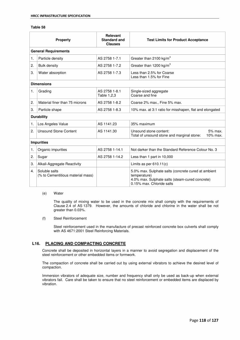
HRCC INFRASTRUCTURE SPECIFICATION
Page 118 of 127
Table 58
Property
Relevant Standard and
Clauses
Test Limits for Product Acceptance
General Requirements
1. Particle density AS 2758 1-7.1 Greater than 2100 kg/m3
2. Bulk density AS 2758 1-7.2 Greater than 1200 kg/m3
3. Water absorption AS 2758 1-7.3 Less than 2.5% for Coarse Less than 1.5% for Fine
Dimensions
1. Grading AS 2758 1-8.1 Table 1,2,3
Single-sized aggregate Coarse and fine
2. Material finer than 75 microns AS 2758 1-8.2 Coarse 2% max., Fine 5% max.
3. Particle shape AS 2758 1-8.3 10% max. at 3:1 ratio for misshapen, flat and elongated
Durability
1. Los Angeles Value AS 1141.23 35% maximum
2. Unsound Stone Content AS 1141.30 Unsound stone content: 5% max. Total of unsound stone and marginal stone: 10% max.
Impurities
1. Organic impurities AS 2758 1-14.1 Not darker than the Standard Reference Colour No. 3
2. Sugar AS 2758 1-14.2 Less than 1 part in 10,000
3. Alkali-Aggregate Reactivity Limits as per 610.11(c)
4. Soluble salts (% to Cementitious material mass)
5.0% max. Sulphate salts (concrete cured at ambient temperature) 4.0% max. Sulphate salts (steam-cured concrete) 0.15% max. Chloride salts
(e) Water
The quality of mixing water to be used in the concrete mix shall comply with the requirements of Clause 2.4 of AS 1379. However, the amounts of chloride and chlorine in the water shall be not greater than 0.03%.
(f) Steel Reinforcement Steel reinforcement used in the manufacture of precast reinforced concrete box culverts shall comply with AS 4671:2001 Steel Reinforcing Materials.
L16. PLACING AND COMPACTING CONCRETE
Concrete shall be deposited in horizontal layers in a manner to avoid segregation and displacement of the steel reinforcement or other embedded items or formwork. The compaction of concrete shall be carried out by using external vibrators to achieve the desired level of compaction. Immersion vibrators of adequate size, number and frequency shall only be used as back-up when external vibrators fail. Care shall be taken to ensure that no steel reinforcement or embedded items are displaced by vibration.

HRCC INFRASTRUCTURE SPECIFICATION
Page 119 of 127
L17. CURING, STRIPPING AND REMOVAL FROM FORMWORK
Concrete shall be cured using one or a combination of methods described in this clause. The concrete shall be protected from moisture loss until commencement of curing, which shall continue until the concrete reaches the age or the maturity, whichever is the lesser, and the compressive strength is as shown in Table 59. The concrete compressive strength for checking the adequacy of curing shall be determined by test cylinders cured with and in the same manner as the concrete unit. The unit shall not be completely stripped from all forms or handled off the base forms until the compressive strength reaches 15 MPa. Curing shall be carried out to meet the requirements of Table 59 and where curing is interrupted by more than 30 minutes the unit shall be protected from moisture loss.
Table 59
Exposure Classification
Minimum Characteristic
concrete compressive
strength (f’c) at 28 Days (MPa)
Required concrete compressive strength at
completion of accelerated curing MPa
Required minimum concrete age (days) and minimum maturity (°C hrs) at completion of curing
Moist Membrane Accelerated
Age Days
Maturity °C hrs
Age Days
Maturity °C hrs
Age Days
Maturity °C hrs
B1 40 25
7 3864 7 3864 0.25 420 50 32
B2 40 25
7 3864 7 3864 0.25 420 50 32
C 50 32 7 3864 Not permitted 0.25 550
Notes:
1. For concrete exposure classification U, curing should be as specified on the drawings and in this specification. 2. The required concrete compressive strengths at completion of curing are based on Table 4.5 of AS 5100.5—
2004, i.e. compressive strength at completion of curing = 0.625 f’c.
3. Maturity (°C hrs) for moist and membrane curing is calculated by adopting the minimum days x 24 x 23°C. Minimum days are based on Table 4.4 of AS 3600—2009.
4. Maturity (°C hrs) for accelerated curing is calculated by adopting the minimum days x 24 x 70°C.
Where moist curing is used concrete shall be kept continuously moist and the concrete maintained at a temperature above 5°C and all surfaces of the culvert must remain fully saturated. Membrane curing in the form of curing compounds may be used in accordance with Table 59 for exposure classifications B1 and B2 in lieu of moist curing. Curing compounds shall be applied to all exposed concrete surfaces to manufacturer’s specifications. The concrete shall be maintained at a temperature above 5°C. Curing compounds shall comply with the requirements of AS 3799. Accelerated curing shall be carried out by low pressure steam curing in accordance with Appendix C of AS 1597.1.
L18. SAMPLING AND TESTING FOR COMPRESSIVE STRENGTH
A sample consisting of a minimum of four concrete compression cylinders shall be taken at not greater than ten hours of continuous manufacture of culvert units and tested for strength. The concrete compression cylinders shall be made in accordance with AS 1012.1 and AS 1012.8 and subsequently tested in accordance with AS 1012.9. The minimum compressive strength requirements for each strength grade shall be in accordance with Clause L17 and as shown in Table 59. Curing of concrete compression cylinders shall be carried out in accordance with AS 1012.8. Concrete compression cylinders shall be cured initially with the product. As soon as practicable after a period of 18 hours from moulding, the test cylinders shall be placed under standard moist curing conditions. The time between moulding and entry into standard moist curing conditions shall not exceed 36 hours.
HRCC INFRASTRUCTURE SPECIFICATION
Page 120 of 127
L19. CONCRETE COVER TO STEEL REINFORCEMENT
The tolerance on concrete cover shall be 0 to +5 mm. For normal service conditions spacers or bar chairs used to maintain cover to the steel reinforcement shall be made of plastic or steel, provided the box culvert is manufactured using rigid formwork and intense vibration. Where box culverts are to be placed in saltwater applications, stainless steel spacers or plastic bar chairs shall be used. The concrete cover to the steel reinforcement shall be measured with a calibrated cover meter to ensure compliance with the requirements of Clause L14. The Contractor shall select one unit for concrete cover measurements from each 100 units of a batch or a maximum period of 3 months production. The cover meter device shall be capable of detecting the presence of reinforcement and indicating the depth from the concrete surface to the nearest point on the surface of the reinforcement with an accuracy of ± 1 mm at a depth of 25 mm.
L20. PROVISION FOR LIFTING AND HANDLING OF UNITS
Units shall be handled in a manner which will avoid damage to them and shall be lifted using the lifting points provided. Where units are lifted in the legs-up position, a lifting beam shall be used in order to avoid inducing excessive bending moments. Precast units shall not be handled before the concrete has reached compressive strength of 15 MPa and stored in a manner such that their: (a) serviceability is not impaired; (b) shape is not distorted to affect installation alignment; and (c) surface and edge finishes are not unduly damaged.
Provision shall be made for lifting and handling the precast units. Where lifting inserts are provided, they shall be installed in accordance with the lifting inserts supplier’s recommendations. All provisions for lifting shall comply with the requirements of the appropriate regulatory authority.
L21. WORKMANSHIP AND FINISH
All units shall be free from fractures, cracks and from any other defects.
(a) Surface Condition
The interior and exterior surfaces of the units shall be smooth and dense and free from voids, chipped edges, fins, protrusions, surface roughness and other defects. Blowhole defects 6 mm diameter and 3 mm deep will be accepted provided that there are no more than 5 defects in an area 300 mm square, or an equivalent area of larger or smaller diameter holes providing they are not more than 3 mm deep. Units with defects greater than this allowance shall be rejected. Units shall not be coated with cement wash or any other preparation.
(b) Dents, Bulges and Defects Dents not exceeding 3 mm deep, and bulges not exceeding 3 mm high, shall be accepted provided they do not extend over the surface for a distance greater than twice the wall thickness of the unit, and provided that the minimum cover is maintained. Dents shall be repaired by the Contractor if necessary to maintain the minimum cover. Units shall be free from fractures and cracks wider than 0.15 mm and residual test cracks wider than 0.08 mm in accordance with the requirements of Clause L24 and Appendix E of AS 1597.1.

HRCC INFRASTRUCTURE SPECIFICATION
Page 121 of 127
L22. IDENTIFICATION OF UNITS
All units shall be clearly stencilled by the Contractor with indelible ink on the interior surface of each unit prior to inspection. Lids shall be stencilled on the underside and base slabs on the top side. Information required on each unit shall be as follows: (a) nominal dimensions (b) date of manufacture and identification number (c) name of the manufacturer and/or its registered trade mark (d) locality of the supplying factory (e) maximum mass of the unit (f) number of the relevant Australian Standard, i.e. AS 1597.1.
L23. TESTING AT THE MANUFACTURERS WORKS
A batch is defined as a maximum of 50 number units of the same size and manufactured and cured at the same works within two calendar months. Units supplied from more than one source, or manufactured outside of a two month period, then those units shall be deemed to be more than one batch and the requirements of the specification shall apply to each separate batch.
L24. PROOF LOAD TEST
From each 25 units of a batch, the Contractor shall select one unit as defined in Clause L11 for proof-load testing in accordance with AS 1597.1. The two test units shall represent the first sample for the batch. For batches of less than 25 units, a sample of one unit shall be selected by the Contractor for proof-load testing. Every selected unit not more than 1.22 metres long shall sustain a vertical force of 112 kN without developing a test crack as defined in Note 1, and on removal of the load, no crack caused by the load shall be greater than that defined in Note 2 below as a residual test crack. For batches greater than 25 units, if: (a) in the first sample two non-conforming units are found, then reject the batch; or (b) one unit in the first sample is non-conforming, select a second random sample of two units, one unit
from each 25 units of the same batch, and subject them to the same crack load test in accordance with AS 1597.1. If any unit in the second sample fails, then reject the batch. If no units in the second sample fail, accept the batch.
For batches of less than 25 units, should the sample test unit fail to comply then select a random second sample of one additional unit from the same batch and subject it to the same crack load test in accordance with AS 1597.1. If the unit in the second sample fails, reject the batch. If no non-conforming unit is found in the second sample, accept the batch.
Note 1: A test crack is defined as one into which the point of a test crack measuring gauge conforming to
the details given in Figure E1 of AS 1597.1 may be inserted to a depth of 2 mm over a length of at least 300 mm at intervals not exceeding 50 mm.
Note 2: A residual test crack is defined as one into which the point of a residual test crack measuring
gauge conforming to the details given in Figure E1 of AS 1597.1 may be inserted to a depth of 2 mm over a length of at least 300 mm at intervals not exceeding 50 mm.
L25. ULTIMATE LOAD TEST
From each 25 units of a batch, the Contractor shall select one unit for ultimate-load testing in accordance with AS 1597.1. The two test units shall represent the first sample for the batch. For batches of less than 25 units, a sample of one unit shall be selected by the Contractor for ultimate-load testing. Every selected unit not more than 1.22 metres long shall sustain a vertical force of 202 kN.

HRCC INFRASTRUCTURE SPECIFICATION
Page 122 of 127
For batches greater than 25 units, if: (a) in the first sample two non-conforming units are found then reject the batch; or (b) one unit in the first sample fails to comply, select a second random sample of two units, one unit from
each 25 units of the same batch, and subject them to the same ultimate load test in accordance with AS 1597.1. If any unit in the second sample fails, then reject the batch. If no units in the second sample fail, accept the batch.
For batches of less than 25 units, should the sample test unit fail to comply with the requirements of this clause then select a random second sample of one additional unit from the same batch and subject it to the same ultimate load test in accordance with AS 1597.1. If the unit in the second sample fails, reject the batch. If no non-conforming unit is found in the second sample, accept the batch.
L26. LOAD TESTING OF 2.44 METRE UNITS
For unit sections of 2.44 m, the loads specified for proof and ultimate test shall be applied over each 1.22 m end of the culvert either separately or at both ends simultaneously. When the unit is loaded at both ends simultaneously, the specified load for proof and ultimate shall be doubled.
L27. CALIBRATION OF TESTING MACHINE
The testing machine used for load testing shall meet the requirements of AS 2193 Class B and shall be calibrated in accordance with the terms of laboratory accreditation for the specific testing machine type. A jack and pressure gauge system may be used provided that calibration is carried out at not more than six monthly intervals.
L28. TRANSPORT AND STORAGE
(a) Transporting
Units shall not be transported from the precast yard within seven days after casting and the curing has been completed. Units shall be supported on timber bearers which are fitted with rubber strips on top. Rubber strips shall also be placed between units, both laterally and longitudinally. All tie down straps and chains shall have rubber protection strips over box culvert edges. The legs of all box culverts shall be adequately braced to prevent whipping and bending. The precast invert base slabs and lids to be transported shall be loaded in the laid position.
(b) Stacking
(i) Inverts or crowns shall be stored in separate stacks of identical units up to a maximum height of 2 metres or two units high separated by timber packers.
(ii) Lids or base slabs shall be stored in separate stacks of identical units up to a maximum height of six units separated by timber packers.
(c) Final Visual Inspection of Units upon Delivery to Site
The Contractor shall undertake a final visual inspection of units upon transport and delivery to site and the findings of such inspection shall form part of the acceptance requirements.
L29. ACCEPTANCE
Box culverts shall be accepted on the basis of full compliance with the requirements of this section and AS 1597.1. Documentation supporting the following quality requirements shall be submitted for review by the Superintendent upon transport and delivery of units to site:

HRCC INFRASTRUCTURE SPECIFICATION
Page 123 of 127
(a) visual inspection (b) dimensional measurements (c) measurements of clear cover to steel reinforcement (d) concrete compressive strength test results (e) proof load test results (f) ultimate load test results.
PRECAST CONCRETE UNITS
L30. GENERAL
This section covers the manufacture, storage, handling and delivery of precast concrete units.
L31. FORMS
Forms shall be manufactured from steel, except where otherwise approved by the Superintendent. The formwork shall be constructed so as to produce the finished concrete to the shape, lines and dimensions shown on the drawings, and in accordance with the surface finish and tolerances specified in Clause L13. Void formers shall be securely restrained in position vertically against the action of placing concrete and subsequent flotation under vibration. The void former shall likewise be laterally restrained against forces arising from differential pressures during placing of concrete. The use of wires or bolts extended to the surface of the concrete will not be permitted except where shown on the drawings. Any embedded ties shall remain embedded and shall terminate not less than the specified concrete cover. All recesses shall be filled to the satisfaction of the Superintendent
L32. REMOVAL OF UNITS FROM FORMS
Individual precast units with mass of five tonnes or less shall have a minimum concrete compressive strength of 10 MPa for removal of units from forms. For individual precast units of mass greater that five tonnes, the minimum concrete compressive strength shall be 20 MPa for removal of units from forms. Lifting of precast units at a minimum concrete compressive strength other than that specified in this clause shall be supported with structural calculations and maturity testing for estimating the in situ strength of concrete. The structural calculations shall be certified by an Engineer who has qualifications admitting to Corporate Membership of the Institution of Engineers, Australia, with a minimum of five years experience in structural design.
L33. PROJECTING REINFORCEMENT
Where shown on the drawings, steel reinforcement shall be left projecting for the purpose of bonding on subsequent work. Care shall be taken to avoid disturbing the bars during the specified period for curing of the concrete. Projecting reinforcement which has been damaged or dislodged or which is loose in the concrete will be cause for rejecting of the units. Continuity bars shall be positioned within 3 mm of the positions shown on the drawings. The relative deviation of any two bars cross sections, taken at right angles to the longitudinal centreline of the unit over the projecting length of bar, shall be within 3 mm.
L34. SOLE PLATES AND BEARING RETAINERS
Material for sole plates and bearing retainers shall be of structural grade steel complying with the requirements of AS 3678. All surfaces and edges of sole plates shall be finished smooth and bearing surfaces shall have a maximum out of flatness of 0.4 mm unless otherwise specified on the drawings. Prior to galvanizing, the surface finish on edges shall be equivalent to a Class 1 flame cut surface as specified by the Australian Welding Research Association. Welding shall comply with the requirements of AS/NZS 1554, Part 1. Unless otherwise specified, steel sole plates shall be galvanized in accordance with the requirements of AS/NZS 4680. The minimum mass of zinc coating shall be 0.6 kg/m
2 of surface.

HRCC INFRASTRUCTURE SPECIFICATION
Page 124 of 127
Sole plates shall be set to the required grades shown on the drawings, or as specified by the Superintendent. They shall be arranged so that the bearing surfaces are at right angles to the vertical axis of the unit.
L35. MARKING
The identification number, date of casting, the manufacturer’s name or registered mark and the maximum mass shall be marked on every precast unit. Temporary identification shall be made on the top surface of the unit near an end, except for parapet units. Final marking shall be made by indelible marking material, using letters approximately 40 mm high. For parapet units, temporary identification shall be made on the broomed surface of the parapet as shown on the drawings. Final markings shall be made on one end of each unit. Piles shall be marked and numbered at 500 mm increments starting from the toe with an indelible marking material.
L36. HANDLING AND STORAGE
Units shall not be stored in areas subject to flooding. Units shall not be stored within 10 m of existing or proposed overhead power or telephone lines, or over service conduits, drainage pipes or uncompacted fill. The units shall be supported on bearers clear of the ground. Bearers shall support the units over their full width and be placed perpendicular to the longitudinal axis of the unit. Unless specified otherwise, bearers shall be placed beneath the specified or approved lifting points clear of any sole plates. The ground or space between the bearers supporting the units shall be carefully cleared and levelled so as to prevent the unit from being supported other than on the bearers. The bearers shall rest on a firm foundation, and adequate precautions shall be taken to prevent subsidence from occurring and to prevent the units bearing other than at the specified support positions. Any units damaged or distorted in excess of the specified tolerances prior or during installation shall be replaced at the Contractor’s expense. Where the method of handling and supporting is not specified, the Contractor shall submit, for review by the Superintendent, details of his proposals 14 days prior to lifting and supporting the units. Unless otherwise specified, precast units shall be lifted using the lifting points provided and supported with the top surface uppermost at all times. The angle subtended by the slings and the longitudinal axis of the unit shall be not less than 60°. Beams shall be stored and handled with webs vertical at all times. All beams shall be laterally supported. The lateral bracing shall be designed for 10% of the dead load of the beam at the mid height of the beam. Beams and parapet units shall not be stored in stacks. Slabs, planks and piles may be stored in separate stacks of identical units up to a maximum height of 2 m, or two units high, whichever is greater. Crown units may be stored in separate stacks of identical units up to a maximum height of 3 m. The upper layers shall be separated from the lower layers by suitable timber bearers in line vertically at the specified supporting points. Timber supports for upper layers shall be placed directly above the supports of the layer below.
L37. TRANSPORTING
Units shall not be transported from the precast yard until specified 28 day concrete compressive strength has been achieved, and not before 7 days after casting. Units shall be securely fixed to the transporter and provision shall be made to protect the units from damage caused by lashings. During transport of beam units the Contractor shall provide end bracing and, if necessary, top flange bracing. Bearings and supports shall allow for longitudinal rotation of the unit in transport and have adequate width and bearing capacity.

HRCC INFRASTRUCTURE SPECIFICATION
Page 125 of 127
No beam shall be transported and erected if it has a bow in excess of 1 in 400 of the length or 75 mm whichever is the lesser. Should the bow at any time exceed the maximum allowable limit steps shall be taken to ensure the safety of the unit throughout the journey.
L38. TRACEABILITY OF PRECAST CONCRETE UNITS
All manufactured precast concrete units shall be traced from the completion of manufacture to their final location by a unique identification number.
INSTALLATION OF PRECAST CONCRETE CROWN UNIT CULVERTS L39. GENERAL
This section specifies requirements for the installation of reinforced precast concrete crown unit culverts and the associated cast-in-place concrete.
L40. TOLERANCES FOR PLACEMENT OF UNITS
The culvert shall be constructed in the location and to the alignment shown on the drawings with the following tolerances:
1. Grade 5 mm in 5 m (1 in 1000)
2. Overall plan position 50 mm
3. Gap between adjacent units 12 mm maximum
4. Step at joint between adjacent units 12 mm maximum horizontal or vertical. L41. DIVERSION AND DISPOSAL OF WATER
Before obstructing or diverting any waterway, stream or channel for construction purposes, the Contractor shall obtain the written approval of the relevant authority to construct the obstruction or diversion. The Contractor shall observe all requirements imposed by the relevant authority and included in the written approval. A copy of the written approval shall be provided to the Superintendent prior to the commencement of work. The Contractor shall: • divert or dispose of water where necessary to enable construction of the culvert; • devise and install measures to prevent the escape of sediment and/or construction materials into the
watercourse; • implement appropriate measures to prevent damage to other parts of the works or surrounding
properties that might result from the temporary modification of flows. The Contractor shall rectify any damage that may occur to the works or to adjacent properties to the satisfaction of the Superintendent.
The Contractor shall produce a written declaration from the relevant authority that the waterway has been left in a satisfactory condition prior to Practical Completion.
L42. EXCAVATION
Excavation shall be as shown on the drawings. The required ground bearing pressure shall be as stated on the drawings. Excavation for the culvert shall include all excavation necessary to provide the specified depth of bedding to place the units and associated walls, working space and space required for filling, including the removal and replacement of unsuitable material below the level of the underside of the bedding. The foundation material at the level of the underside of the bedding shall be test rolled in accordance with Clause B53. Foundation material that is soft, excessively wet, unstable or that does not comply with the requirements for test rolling or does not achieve the required ground bearing pressure stated on the drawings shall be treated as unsuitable material. Such unsuitable material shall be excavated and replaced with 40 mm Class 3 crushed rock, spread in layers not exceeding 150 mm compacted thickness and compacted to achieve the required ground bearing pressure stated on the drawings.

HRCC INFRASTRUCTURE SPECIFICATION
Page 126 of 127
When the foundation is in rock, all loose rock and pockets of unsound material, mud or water, shall be removed to expose the sound rock and the surface shall be brought to level as necessary with blinding concrete. The excavation shall be supported in accordance with the requirements of Clause E16.
L43. BEDDING
Bedding material shall comply with the requirements of Clause E8. Bedding for the cast-in-place concrete base slab shall consist of a compacted layer of 20 mm Class 3 crushed rock, of not less than 150 mm compacted thickness. Where shown on the drawings, this material shall be placed on 40 mm Class 3 crushed rock spread in layers not exceeding 150 mm compacted thickness and compacted to achieve the required bearing pressure specified on the drawings.
L44. CAST-IN-PLACE CONCRETE
Cast-in-place concrete for bedding slabs shall comply with the drawings and the requirements of Section F. Steel reinforcement shall comply with the drawings and the requirements of Clause AS 4671:2001 Steel Reinforcing Materials.
L45. PLACING CROWN UNITS
The cast-in-place concrete base slab shall be cured and achieve the 28 day minimum compressive strength shown on the drawings before any precast concrete units are placed. Immediately prior to placing crown units, the surfaces of the bearing areas which support the crown units shall be cleaned, wetted and then covered with sufficient stiff mortar to give a finished thickness not less than 5 mm and not more than 10 mm after the crown units have been placed. The mortar shall consist of cement and clean sand at a ratio of 1:3 and mixed to a consistency that can be displaced to provide an even bearing. The crown units shall be placed in position before the mortar has stiffened to ensure that a uniform bearing is achieved. Lifting loops shall be cut off flush with the top surface of the units and covered with a minimum 15 mm thickness of epoxy mortar.
L46. CONSTRUCTION LOADING ON CULVERTS
If construction vehicles or plant are required to cross the culvert at any time before completion of the road construction, the Contractor shall construct a temporary riding surface over the culvert. Construction vehicles or plant with axle load-effects (including the load due to the actual depth of construction or temporary riding surface) that exceed the design load-effect shall not be permitted to pass over the culvert at any time without the approval of the Superintendent. The Contractor shall submit its proposals (including supporting calculations) to move such vehicles to the Superintendent for review not later than two weeks prior to the proposed movement. The temporary riding surface shall have a smooth profile to produce a surface free from ruts and bumps. The depth of the temporary riding surface shall be determined by the Contractor but shall be not less than 600 mm. Construction vehicles or plant shall not pass over the culvert: • until at least 28 days has elapsed following casting of the base slab; or • until at least 7 days has elapsed following casting, provided that the cylinder strength of the base slab
concrete has achieved 20 MPa.
If vibrating rollers are required to work on or move over the temporary riding surface, the axle load for determining the required depth of cover shall be the combined static and dynamic load. The Contractor shall maintain the temporary riding surface for the period during which construction traffic is required to pass over the culvert and shall remove it prior to construction of the final embankment and pavement. The temporary materials may be left in place at the discretion of the Superintendent subject to the suitability of the material, its density and condition.

HRCC INFRASTRUCTURE SPECIFICATION
Page 127 of 127
END OF DOCUMENT