Interconnection Requirements For Distributed Generation ... · Interconnection Requirements . For ....
46
Effective August 2009 Rev 6.1 (2009) Interconnection Requirements For Distributed Generation Arizona Public Service Company
Transcript of Interconnection Requirements For Distributed Generation ... · Interconnection Requirements . For ....

Effective August 2009 Rev 6.1 (2009)
Interconnection Requirements
For
Distributed Generation
Arizona Public Service Company

INTERCONNECTION REQUIREMENTS FOR DISTRIBUTED GENERATION
1
TABLE OF CONTENTS
1 INTRODUCTION .................................................................................................................................... 2
2 DEFINITIONS......................................................................................................................................... 4
3 APS POLICY ON CUSTOMER-OWNED GENERATION...................................................................... 9
4 DISTRIBUTED GENERATION TYPES................................................................................................ 11
5 CUSTOMER RESPONSIBILITIES....................................................................................................... 13
6 MUTUAL UNDERSTANDINGS ........................................................................................................... 15
7 DESIGN CONSIDERATIONS AND DEFINITION OF CLASSES........................................................ 17
8 INTERCONNECTION TECHNICAL REQUIREMENTS....................................................................... 19
9 METERING REQUIREMENTS............................................................................................................. 31
10 RATE SCHEDULES APPLICABLE TO DISTRIBUTED GENERATION............................................ 32
11 APPLICATION PROCESS AND GENERAL REQUIREMENTS......................................................... 33
12 TESTING AND START-UP REQUIREMENTS.................................................................................... 34
13 OPERATIONAL AND MAINTENANCE REQUIREMENTS................................................................. 35
APPENDIX A .............................................................................................................................................. 36

INTERCONNECTION REQUIREMENTS FOR DISTRIBUTED GENERATION
2
1 INTRODUCTION This manual specifies the minimum requirements for safe and effective operation of distributed generation interconnected (or paralleled) with the Arizona Public Service Company (APS) radial distribution system (21 kV or less). For installations not subject to APS’ Open Access Transmission Tariff (“OATT”) as described below, application for interconnection is made by completing and submitting to APS the applicable Interconnection Application (Static Inverter or Rotating machinery) along with the required Supplementary Information specified in Appendix A at the back of this manual. Installations that are directly connected to, or backfeed onto the transmission system or engage in sale for resale to entities other than APS have additional APS requirements. In such cases an interconnection application needs to be made in accordance with APS’ Open Access Transmission Tariff (“OATT”). Further information can be obtained by accessing the following website: http://www.oatioasis.com/azps/index.html and clicking on the link entitled Applications. For the purpose of simplicity, the term "Customer" will be used here to refer to any distributed generator, cogenerator or small power producer, even though they may not actually be purchasers of power from APS, and includes any independent party or entity that either invests in, owns or operates a distributed generator or generation facility. Customers applying for the interconnection of certain static inverter systems in conjunction with making an application to participate in a distributed generation incentive program being offered by APS may be allowed to complete a different interconnection application other than that included in Appendix A. Additional information is available on the aps.com website. However, it is important to note that regardless of the interconnection application submitted, the interconnection technical requirements outlined in this document govern. Customers and APS personnel shall use this document when planning the installation of distributed generation. Note that these requirements may not cover all details in specific cases. The Customer should discuss project plans with APS before designing the facility or purchasing and installing equipment. This manual must be applied in conjunction with the following APS documents that pertain to the parallel operation of Customer-owned distributed generation with the APS electrical distribution system:
• Schedule #1, Terms and Conditions for the Sale of Electric Service • Schedule #2, Terms and Conditions for Energy Purchases from Qualified
Cogenerators and Small Power Production Facilities • Schedule #5, Guidelines for Electric Curtailment. • APS Electric Service Requirements Manual (“ESRM”)
INTERCONNECTION REQUIREMENTS FOR DISTRIBUTED GENERATION
3
The minimum required protective relaying and/or safety devices and requirements specified in this manual, are for protecting only APS facilities and the equipment of other customers from damage or disruptions caused by a fault, overcurrent condition, malfunction or improper operation of the distributed generating facility. These Requirements are also necessary to ensure the safety of utility workers and the public. Minimum protective relaying and interconnection requirements do not include additional relaying, protective or safety devices as may be required by industry and/or government codes and standards, equipment manufacturer requirements and prudent engineering design and practice to fully protect Customer’s generating facility or facilities; those are the sole responsibility of the Customer. The information contained in this manual contains general information about the interconnection requirements for customer-owned distributed generation. In addition to all applicable regulatory, technical, safety, and electrical requirements and codes, which are not contained in their entirety in this manual, Customers will also be subject to contractual and other legal requirements, which are only summarized in this manual. Those regulations, requirements, contracts and other materials contain complete information concerning interconnection and govern over the general provisions in this manual. The technical interconnection requirements outlined in this manual shall also apply to any interconnected utility owned or operated distributed generation facility. This document, as well as the various Agreements and rate schedules, is subject to revision from time to time. Please check with APS for the latest revision prior to commencing with your project. APS is committed to making sure that interconnection applications are handled promptly, and to do everything possible to complete the interconnection process in a safe and timely manner. At APS, we look forward to working with you to ensure a successful generation project.

INTERCONNECTION REQUIREMENTS FOR DISTRIBUTED GENERATION
4
2 DEFINITIONS The following terms, as used in this manual, shall have the meanings specified: AHJ: Authority Having Jurisdiction. The organization, office, or individual responsible for enforcing the requirements of a code or standard or for approving equipment, materials, an installation, or a procedure. ANSI: American National Standards Institute. See www.ansi.org. Application: The standard form for applying to interconnect a Generating Facility with the Utility system also referred to as the “Interconnection Application”. APS: Arizona Public Service Company Arizona Corporation Commission (“ACC” or “Commission”): The regulatory agency of the State of Arizona having jurisdiction over public service corporations operating in Arizona. Backfeed: To energize a section of a Utility electric system that is supplied from a source other than its normal source. Business Day: Monday through Friday, excluding Federal and Arizona State Holidays. Clearance: A Clearance is a statement by one having complete authority over all parts of a circuit or piece of electrical equipment that said circuit or equipment is disconnected from all known sources or power. It is assurance that all proper precautionary measures have been taken and workers may proceed with grounding the circuit. Clearance Point: The physical location on a section of a power line or equipment that is to be visibly disconnected from all known power sources of power. Cogeneration Facility: Any facility that sequentially produces electricity, steam or forms of useful energy (e.g., heat) from the same fuel source and which are used for industrial, commercial, heating, or cooling purposes. Customer: An electric consumer that generates electricity on the consumer’s side of the Utility meter. For the purpose of this document a Customer is considered to be the APS Account Holder or Customer of Record. A Customer may include any independent party or entity that either invests in, owns or operates a Generating Facility. Disconnect Switch: A visible open disconnect device that the Customer is required to install and maintain in accordance with the requirements set forth in this document. It will completely isolate the Customer's Generating Facility from the Utility grid. Distributed Generation (DG): Any type of electrical generator, static inverter or Generating Facility interconnected with the Distribution System that either (a) has the capability of being operated in electrical parallel with the APS distribution system, or (b)

INTERCONNECTION REQUIREMENTS FOR DISTRIBUTED GENERATION
5
can feed a customer load that can also be fed by the APS electrical system. A distributed generator is often referred to as a “Generating Facility” or “generator” in this document. Distribution System: The infrastructure constructed, maintained, and operated by APS to deliver electric service at the distribution level (21 kW or less) to retail customers.
ESRM: APS Electric Service Requirements Manual. See http://esp.aps.com/resource/esrm.asp Electric Supply/Purchase Agreement: An agreement, together with appendices, signed between APS and the Customer covering the terms and conditions under which electrical power is supplied to and/or purchased from APS. Fault Current: The level of current that can flow if a short circuit is applied to a voltage source. Generator: An induction or synchronous machine or static inverter used to produce electrical power. Generating Facility (GF): All or part of the Customer’s electrical generator(s) or inverter(s) together with all protective, safety, and associated equipment necessary to produce electric power at the Customer’s facility. A Generating Facility also includes any Qualifying Facility (QF). Good Utility Practice: Any of the practices, methods, and acts engaged in or approved by a significant portion of the electric industry during the relevant time period, or any of the practices, methods, and acts which, in the exercise of reasonable judgment in light of the facts known at the time the decision was made, could have been expected to accomplish the desired result at a reasonable cost consistent with good business practices, reliability, safety, and expedition. Good Utility Practice is not intended to be limited to the optimum practice, method, or act to the exclusion of all others, but rather to be acceptable practices, methods, or acts generally accepted in the region. IEEE: The Institute of Electrical and Electronic Engineers. See www.ieee.org. Interconnection: The physical connection of the Customer’s Generating Facility to the Utility system. Interconnection Agreement: An agreement, together with appendices, signed between APS and the Customer, covering the terms and conditions governing the Interconnection and parallel operation of the Generating Facility with APS. Interconnection Generation Design Review Agreement: An agreement signed between APS and the Customer covering the terms for APS to proceed with a detailed study of the impact of the Customer’s DG on APS’ System.

INTERCONNECTION REQUIREMENTS FOR DISTRIBUTED GENERATION
6
Interconnection Study: A study or studies that may be undertaken by APS (or an APS designated third party) in response to its receipt of a completed Application for Interconnection and parallel operation with the APS system. Interconnection studies may include, but are not limited to, Interconnection Feasibility Studies, System Impact Studies, and Facilities Studies. Island: A condition in which a portion of a Utility electric power system is energized solely by one or more local electric power systems throughout the associated Point of Interconnection while that portion of the Utility electric power system is electrically separated from the rest of the Utility electric power system. Metering: The function related to measuring the transfer of electric power and energy. Minimum Protective Devices, Relays, and Interconnection Requirements: The minimum required protective relaying and/or safety devices or requirements specified in this manual, as may be revised from time to time, for the purpose of protecting only APS and its other customer facilities from damage or disruptions caused by a fault, malfunction or improper operation of the Customer’s GF. Minimum Protective Relaying and Interconnection Requirements do not include relaying, protective or safety devices as may be required by industry and/or government codes and standards, equipment manufacturing and prudent engineering design and practice to fully protect the Customer’s GF or facilities; those are the sole responsibility of the Customer. Momentary Parallel System: A Momentary Parallel System is one that transfers electrical load between the Utility grid and the Customer’s Generating Facility by means of a “make-before break” transfer scheme. Momentary Parallel Systems synchronize the Generating Facility with the Utility grid for a period not to exceed ten seconds for the purpose of uninterrupted load transfer. NEC: National Electric Code. See www.necdirect.org NEMA: National Electrical Manufacturers Association. See www.nema.org. NFPA: National Fire Protection Association. See www.nfpa.org. Non-Parallel Connection Agreement: An agreement, together with appendices, signed between APS and the Customer, covering the terms and conditions governing the non-parallel connection and operation of the Generation Facility with APS. OSHA: Occupational Safety and Health Administration. See www.osha.com Parallel System: A Generating Facility that is electrically interconnected to a bus common with the Utility’s electric distribution system, and operates in parallel either on a momentary or continuous basis. Point of Interconnection: The physical location where APS’ service conductors are connected to the Customer’s service conductors or bus to allow parallel operation of the Customer’s Generating Facility (GF) with APS’ electric distribution system.

INTERCONNECTION REQUIREMENTS FOR DISTRIBUTED GENERATION
7
Primary Network: An AC power distribution system that uses two or more dedicated primary voltage feeders, connected in parallel, to simultaneously supply power to one customer. The system includes automatic protective devices intended to isolate faulted primary feeders, while maintaining uninterrupted service to the customer served from the other primary feeder circuit(s). Qualifying Facility (QF): Any Cogeneration or Small Power Production Facility that meets the criteria for size, fuel use, efficiency, and ownership as promulgated in 18 CFR, Chapter I, Part 292, Subpart B of the Federal Energy Regulatory Commission’s Regulations. Radial Line: A distribution line that originates from a substation and is normally not connected to another substation or another circuit sharing the common supply of electric power. Reclosing: The act of automatically re-energizing a utility line in an attempt to restore power. Relay: An electric device that is designed to interpret input conditions in a prescribed manner and after specified conditions are met to respond to cause contact operation or similar abrupt change in associated electric control circuits. Secondary Spot Network System: An AC power distribution system in which a Customer is simultaneously served from three-phase, four-wire low-voltage (typically 480V) circuits supplied by two or more network transformers whose low-voltage terminals are connected to the low-voltage circuits through network protectors. The low voltage circuits do not have ties to adjacent or nearby secondary network systems. The secondary spot network system has two or more high-voltage primary feeders. These primary feeders are either dedicated network feeders that serve only other network transformers, or a non-dedicated network feeder that serves radial transformers in addition to the network transformer(s), depending on network size and design. The system includes automatic protective devices and fuses intended to isolate faulted primary feeders, network transformers, or low-voltage cable sections while maintaining uninterrupted service to the customers served from the low-voltage circuits. Separate System: The operation of a Generating Facility that has no possibility of operating in parallel with, or backfeeding onto, APS’ system. SES: Service Entrance Section. The Customer-owned main electrical panel or equipment located at its premises to which the Utility delivers electric energy via the Utility service drop or service lateral. Small Power Production Facility: A facility that uses primarily biomass, waste or renewable resources, including wind, solar, and water to produce electric power. Transfer Switch: An automatic or manually operated device for transferring one or more load conductor connections from one power source to another (e.g. Generating Facility).

INTERCONNECTION REQUIREMENTS FOR DISTRIBUTED GENERATION
8
Transfer Trip Scheme: A form of remote trip in which a communication channel is used to transmit a trip signal from the relay location (e.g. utility substation) to a remote location (e.g. Generating Facility). Transmission System: Utility-owned high-voltage lines (69 kV or higher) and associated equipment for the movement or transfer of electric energy between power plants and the distribution system. UL: Underwriters Laboratories Inc. See www.ul.com. Utility: The electric distribution company (APS) that constructs, operates and maintains the electrical distribution system for the receipt and/or delivery of power. Utility-grade Relays: Relays specifically designed to protect and control electric power apparatus, tested in accordance with the following ANSI/IEEE standards:
(a) ANSI/IEEE C37.90-1989 (R1994), IEEE Standard for Relays and Relay Systems Associated with Electric Power Apparatus.
(b) ANSI/IEEE C37.9.01-1989 (R1994), IEEE Standard Surge Withstand (SWC)
Tests for Protective Relays and Relay Systems.
(c) ANSI/IEEE C37.90.2-1995, IEEE Standard Withstand Capability of Relay Systems to Radiated Electromagnetic Interference from Transceivers.

INTERCONNECTION REQUIREMENTS FOR DISTRIBUTED GENERATION
9
3 APS POLICY ON CUSTOMER-OWNED GENERATION Any Customer qualified under the Public Utility Regulatory Policies Act (PURPA) of 1978, may operate his generating equipment in parallel with the APS radial distribution system provided the Customer provides equipment that will:
(a) not present any hazards to APS personnel, other customers or the public, (b) minimize the possibility of damage to APS and other customer equipment, (c) not adversely affect the quality of service to other customers, and (d) minimally hamper efforts to restore a feeder to service (specifically when a
clearance is required).
In addition, the Customer must comply with the following prior to ever paralleling a generator or inverter with APS:
(a) The Generating Facility must meet all the minimum interconnection, safety, and protection requirements outlined in this manual,
(b) Customer must sign an Interconnect Agreement, as well as an Electric Supply /Purchase Agreement, as applicable, with APS,
(c) Customer must comply with and is subject to all applicable service and rate schedules and requirements, rate tariffs and other applicable requirements as filed with and approved by the Arizona Corporation Commission, and
(d) The Generating Facility must be inspected by APS and written permission to parallel must be obtained from APS.
It is the policy of APS to also permit customer generating equipment that does not qualify under PURPA to operate in parallel with the APS radial distribution system provided that all of the conditions outlined above are complied with. Due to relay coordination and potential backfeed problems, APS cannot permit any distributed generation with an AC nameplate output rating of greater than 10 kW to be connected to a Primary or Secondary Spot Network System, without a detailed Interconnection Study being undertaken at Customer’s expense to determine, among other things, special relaying, communication channels and other operational constraints that will need to be implemented. A DG connected to a network system will nonetheless not be permitted to backfeed any power into the APS system. The minimum protective and safety devices (relays, circuit breakers, disconnect switch, etc.) specified in this manual must be installed and placed into service before allowing parallel operation of Customer’s generation facilities with the APS system. The purpose of these devices is to isolate the Customer’s generating equipment from the APS system whenever faults, over-current conditions, or disturbances occur, and also for maintenance purposes. Modifications to the APS electrical system configuration or protective equipment may also be required at the expense of the Customer in order to accommodate parallel generation.

INTERCONNECTION REQUIREMENTS FOR DISTRIBUTED GENERATION
10
APS will not assume any responsibility for the protection of the Customer’s generator(s), or of any other portion of the Customer’s electrical equipment. The Customer is fully and solely responsible for protecting his equipment in a manner to prevent any faults or other disturbances from damaging the Customer’s equipment.
In addition to complying with any other required codes, ordinances and statues, Customer must obtain an electrical permit and inspection indicating that the Customer’s generating facility complies with the NEC. In the event that a Customer’s GF is located in a locality where there is no AHJ, or the AHJ does not issue a permit or perform an inspection of the GF, then the Customer will be required to sign a “Letter-in-Lieu of Electrical Clearance”. APS will forward such letter for Customer’s signature. APS can disallow the interconnection of a Customer’s generating facility if, upon review of the Customer’s design, or as the result of a site inspection, it determines that the proposed design is not in compliance with applicable safety codes, or is such that it could constitute a potentially unsafe or hazardous condition. If APS believes that there may be a potential safety issue or code violation then APS reserves the right to forward the GF diagrams to, and/or discuss same, with the AHJ.

INTERCONNECTION REQUIREMENTS FOR DISTRIBUTED GENERATION
11
4 DISTRIBUTED GENERATION TYPES Distributed generation is any type of generator or generating facility which has the potential (a) for feeding a customer load, where this load can also be fed by, or connected to, the APS electrical distribution system, or (b) for electrically paralleling with, or for feeding power back into APS’ electrical distribution system. Distributed generators include induction and synchronous electrical generators as well as any type of electrical inverter capable of producing A/C power. A Separate System, or Emergency or Standby Generation System, is designed so as to never electrically interconnect or operate in electrical parallel with APS’ system. A Parallel System, or Interconnected Generation System, is as any generator or generation system that can parallel, or has the potential to be paralleled via design or normal operator control, either momentarily or on a continuous basis, with APS’ system.
The Customer may elect to run his generator as a separate system with non-parallel load transfer between the two independent power systems, or he may run it in parallel with the APS system. A description and the basic requirements for these two methods of operation are outlined below. 4.1 Separate System
A separate system is one in which there is no possibility of electrically connecting or operating the Customer’s generation in parallel with the utility's system. The Customer’s equipment must transfer load between the two power systems in an open transition or non-parallel mode. If the Customer claims a separate system, APS may require verification that the transfer scheme meets the non-parallel requirements.
Emergency or Standby generators used to supply part or all of the Customer’s load during a utility power outage must be connected to the Customer’s wiring through a true double throw, “break-before-make” transfer switch specifically designed and installed for that purpose. The transfer switch must be of a fail-safe mechanical throw over design, which will under no circumstances allow the generator to electrically interconnect or parallel with APS’ system. The transfer switch must always disconnect the Customer’s load from APS’ power system prior to connecting it to the generator. Conversely, the transfer switch must also disconnect the load from the generator prior to re-connecting it back to the APS system. These requirements apply to both actual emergency operations as well as to testing the generator. All transfer switches and transfer schemes must be tested to UL Standard 1008 and must be inspected and approved by the AHJ.
Portable generators are not designed to be connected to a building’s permanent wiring system, and are not to be connected to any such wiring unless a permanent and approved transfer switch is used.
INTERCONNECTION REQUIREMENTS FOR DISTRIBUTED GENERATION
12
Failure to use a transfer switch can result in backfeed into the APS system – the generator voltage can backfeed through the APS transformer and be stepped up to a very high voltage. This can pose a potentially fatal shock hazard to anyone working on the power lines or on utility equipment.
Other than the requirements outlined above in this section, APS has no further technical interconnection requirements for a separate system.
4.2 Parallel System
A parallel, or interconnected, generator is connected to a bus common with the utility's system, and a transfer of power between the two systems is a direct result. A consequence of such interconnected operation is that the Customer’s generator becomes an integral part of the utility system that must be considered in the electrical protection and operation of the utility system.
Parallel generators encompass any type of distributed generator or generating facility that can electrically parallel with, or potentially backfeed the utility system. Additionally, any generator system using a “closed transition” type transfer switch or any multi-breaker or multi-switch transfer scheme, or an electrical inverter that can be configured or programmed to operate in a “utility interactive mode” constitutes a potential backfeed source to the APS system, and is classified as an interconnected generator.
APS has specific interconnection, inspection and contractual requirements, as outlined in this manual that must be complied with and information that needs to be submitted for all interconnected generators. These requirements include a “visible open” disconnect switch meeting certain requirements to isolate the Customer’s system from APS’ system, as well as protective relaying, metering, special rate schedules, and other safety and information requirements. The Customer will be responsible for having the generation system protective schemes tested by a qualified testing/calibration company. APS personnel will inspect the system and the Customer will be required to sign an Interconnect Agreement and, as applicable, an Electric Supply/Purchase Agreement with APS. In certain instances, APS and the Customer will need to sign a “Non-Parallel Connection Agreement” and/or an “Operating Agreement”. APS will advise the Customer of any such requirements after reviewing the proposed design. APS does not extend “blanket approval” to any specific type of generator or generator scheme since each project is site specific and needs to be reviewed on a case-by-case basis. In addition to the various other requirements specified in this document, Parallel Systems shall specifically comply with the technical requirements outlined in the Interconnection Technical Requirements section (Section 8) of this document.

INTERCONNECTION REQUIREMENTS FOR DISTRIBUTED GENERATION
13
5 CUSTOMER RESPONSIBILITIES The Customer is responsible for all facilities required to be installed solely to interconnect the Customer’s generation facility to the APS system. This includes connection, transformation, switching, protective relaying, metering and safety equipment, including a visibly-open Disconnect Switch and any other requirements as outlined in this manual, the ESRM and applicable rate schedules as well as any other special items specified by APS. All such Customer facilities are to be installed by the Customer at the Customer’s sole expense. In the event that additional facilities are required to be installed on the APS system to accommodate the Customer’s generation, APS will install such facilities at the Customer’s expense. APS may also charge the Customer for any administrative costs and/or the costs of studies required to interconnect the Customer’s generation. The Customer will own and be responsible for designing, installing, operating and maintaining:
(a) The generating facility in accordance with the requirements of all applicable electric codes, laws and governmental agencies having jurisdiction.
(b) Control and protective devices, in addition to minimum protective relays and devices specified in this manual, to protect its facilities from abnormal operating conditions such as, but not limited to, electric overloading, abnormal voltages, and fault currents. Such protective devices must promptly disconnect the generating facility from APS’ system in the event of a power outage on APS system.
(c) Interconnection facilities on the Customer’s premises which may be required to deliver power from the Customer’s generating facility to the APS system at the Point of Interconnection.
Due to risks associated with interconnecting and operating a distributed generating facility with the APS system, such as serious bodily injury, death or property damage, it is recommended that every Interconnection Customer protect itself with insurance or other suitable financial instrument sufficient to meet its construction, operating and liability responsibilities. APS does not require that the Interconnection Customer negotiate any policy or renewal of any policy covering any liability through a particular insurance provider, agent, solicitor or broker. All interconnected Customers will be required to sign, in addition to any other purchase, supply or other standby or special agreements as may be applicable, an Interconnect Agreement with APS. Customers that connect a static inverter to the utility, and which will be programmed so as not to backfeed into the utility system (i.e. non-utility interactive mode), will need to sign a Non-Parallel Connection Agreement with APS, since such an arrangement can constitute a potential backfeed source.

INTERCONNECTION REQUIREMENTS FOR DISTRIBUTED GENERATION
14
Customers that purchase power from, or sell power to, APS may be required to sign an Electric Supply/Purchase Agreement with APS. In the event that the Customer’s facility is fed by more than one APS electrical service, the Customer will be responsible for installing appropriate electrical equipment and controls to ensure that the APS services will under no circumstances ever paralleled.
INTERCONNECTION REQUIREMENTS FOR DISTRIBUTED GENERATION
15
6 MUTUAL UNDERSTANDINGS 6.1 Interconnections
APS will not install or maintain any lines or equipment on a Customer’s side of the Point of Interconnection, except it may install electric meters and at times research equipment. Only authorized APS employees (with credentials to identify their company affiliation) may make and energize the service connection between the APS system and the Customer’s service entrance conductors.
Normally, the interconnection will be arranged to accept only one type of standard service at one Point of Interconnection. If a Customer’s generating facility requires a special type of service, or if sales to APS will be at a different voltage level, the services will only be provided according to additional specific terms that are outlined in the Electric Supply/Purchase Agreement, applicable rate schedules, or other terms and conditions governing the service.
6.2 Easements and Rights of Way
Where an easement or right of way is required to accommodate the interconnection, the Customer must provide to APS suitable easements or rights of way, in APS’ name, on the premises owned, leased or otherwise controlled by the Customer. If the required easement or right of way is on another’s property, the Customer must obtain and provide to APS a suitable easement or right of way, in APS’ name, at Customer’s sole cost and in sufficient time to meet the Interconnect Agreement requirements. All easements or rights of way must be on terms and conditions acceptable to APS.
6.3 Rate Schedules
The rate applicable to the interconnection of a Customer’s generating facility will depend on the system size, type and configuration. Because of varied and diverse requirements and operating modes associated with the interconnection, the Customer must evaluate and determine which system configuration and electric rate is most appropriate for it and whether or not it qualifies for the particular rate. APS will provide information to assist the Customer to assess the available options. The Customer remains fully responsible for such matters, however, and no APS assistance or information should be taken as constituting any representation or warranty about any particular option.
Any energy purchases from the Customer’s facility will be in accordance with the rate schedule and Electric Supply/Purchase Agreement as applicable, any changes required by law or regulation, and such applicable rates authorized by law. Generating facilities with requirements of unusual size or characteristics may require additional or special rate and contract arrangements.

INTERCONNECTION REQUIREMENTS FOR DISTRIBUTED GENERATION
16
If the purchase of electric energy or capacity would result in greater cost to APS than if APS generated the energy itself or purchased it from another source, APS will not be obligated to buy such energy or capacity from a Customer. When that occurs, APS will give reasonable notice to the Customer so that the Customer may discontinue deliveries or elect to sell to APS at a lower rate.
6.4 ACC JURISDICTION
The rates, terms or other contract provisions governing the electric power sold to a Customer or purchased from the Customer by APS are subject to the jurisdiction of the Arizona Corporate Commission. APS retains at all times and without restriction the right to file a unilateral ACC application for a change in requirements, charges, classification, or service, or any rule, regulation or agreement as allowed by law.

INTERCONNECTION REQUIREMENTS FOR DISTRIBUTED GENERATION
17
7 DESIGN CONSIDERATIONS AND DEFINITION OF CLASSES Protection requirements are influenced by the size and characteristics of the parallel generator along with the nature and operational characteristics of the associated APS system. Therefore, similar units connected to different lines could have different protection requirements based on varying load conditions, as well as on utility feeder and transformer characteristics.
7.1 Synchronous Units
Synchronous generators are generally capable of supplying sustained current for faults on the APS system. These units can also supply isolated APS load providing the load is within the units' output capability.
Reclosing of the utility onto synchronous units must be blocked to prevent out-of-synch paralleling and must also be prevented from energizing a de-energized utility line. Automatic reclosing by APS is time-delayed which allows for automatic Customer generator separation prior to utility circuit re-energization.
7.2 Induction Units
Induction generators are basically induction motors that are mechanically driven above synchronous speed to produce electric power. These units do not have a separate excitation system and, as such, require that their output terminals be energized with AC voltage and supplied with reactive power to develop the magnetic flux. Induction generators are therefore normally not capable of supplying sustained fault current into faults on the utility system. Such units are generally not capable of supplying isolated load when separated from the utility system; however, it is possible for an induction generator to become self-excited if a sufficient amount of capacitance exists at its output terminals. Under conditions of self-excitation, an induction generator will be capable of supplying isolated load, providing the load is within the units' output capability. In most cases when self-excitation occurs it will be accompanied by a sudden increase in terminal voltage. APS and its other customers must be protected from out-of-phase closing and over-voltages that can occur whenever an induction generator becomes self-excited. Induction units must therefore be designed to automatically separate from the utility system upon loss of utility voltage and prior to reclosing of the utility feeder.
7.3 Static Inverters Static inverters convert DC power to AC by means of electronic switching. Switching can be controlled by the AC voltage of the utility's supply system (line-commutated) or by internal electronic circuitry (forced-commutated).

INTERCONNECTION REQUIREMENTS FOR DISTRIBUTED GENERATION
18
Line-commutated inverters are generally not capable of operating independently of the utility's AC supply system and, as such, cannot normally supply any appreciable fault current, or continue to energize isolated loads, provided proper protective functions are in place. To accommodate such protective functions, any line-commutated inverter that is electrically paralleled with the utility system shall be tested to UL Standard for Inverters, Converters and Controllers for use in Independent Power Systems, UL1741 by a Nationally Recognized Testing Laboratory (NRTL) certified by OSHA to perform the UL1741 test standard. Forced-commutated, or self-commutated, inverters are capable of energizing load independently of the utility system. Any forced-commutated inverter, the output of which is to be directly interconnected with the utility, would need to be specifically designed for that purpose, i.e. it would need to be designed to accommodate parallel interfacing and operation. However, it is not anticipated at this time that any forced-commutated inverters will be interconnected to the utility system. APS would consider any such interconnection on a case-by-case basis. Under no circumstance shall the self-commutated output of a “battery backup” inverter which is normally designed to energize a subpanel independently of the utility, be connected to the utility system.
7.4 Definition of Generator Size Classes The following generator size classifications are used in determining specific minimum protective requirements for distributed generation facilities. Specified ratings are for each connection to the APS system. Customers must satisfy, in addition to the general requirements specified in this manual, the minimum relaying requirements given in this document (Section 8.7) for each generator class.
(a) Class I -- 50 kW or less, single or three phase (b) Class II -- 51 kW to 300 kW, three phase (c) Class III -- 301 kW to 5,000 kW, three phase (d) Class IV -- over 5,000 kW, three phase

INTERCONNECTION REQUIREMENTS FOR DISTRIBUTED GENERATION
19
8 INTERCONNECTION TECHNICAL REQUIREMENTS The requirements and specifications outlined in this section are applicable to distributed generation interconnected for parallel operation (continuous or momentarily) with APS’ distribution system, unless otherwise specified. The protection and safety devices and other requirements specified in the following sections are intended to provide protection for the APS system and its workers, other APS Customers, and the general public. They are not imposed to provide protection for the Customer’s generation equipment or personnel. This is the sole responsibility of the Customer. With respect to the above protection objectives, it is necessary to disconnect a parallel generator when trouble occurs. This is to:
(a) ensure if a fault on the APS system persists, the fault current supplied by the Customer’s generator is interrupted;
(b) prevent the possibility of reclosing into an out-of-sync isolated system composed of the utility distribution system, or a section thereof, and the Customer’s generator;
(c) prevent reclosing into the Customer’s generation system that may be out of synchronization or stalled;
(d) prevent unintentional islanding. The protection requirements are minimal for smaller installations, but increase as the size of the Customer’s generation increases. Small installations usually ensure that the generator is small compared with the magnitude of any load with which it might be isolated. Thus, for any fault on the utility system, utility protective devices will operate and normally isolate the generation with a large amount of load, causing voltage collapse and automatic shutdown of the generator. For larger installations the probability of isolated operation is higher since the available generation may be sufficient to carry the entire load, or part thereof, of the local APS circuit. In instances where the APS system arrangement is such that it is possible that the generators will not always be isolated with comparatively large amounts of load, additional protection and generator shutdown schemes are required.
The Customer is solely responsible for the protection of his equipment from automatic reclosing by the utility. APS normally applies automatic reclosing to overhead distribution circuits. When the APS source breaker trips, the Customer must ensure that his generator is disconnected from the utility circuit prior to automatic reclosure by the utility (the automatic reclosing on APS distribution feeders is normally delayed by at least 2 seconds). Automatic reclosing out-of-sync with the Customer’s generator may cause severe damage to Customer equipment and could also pose a serious hazard to Customer or Utility personnel.

INTERCONNECTION REQUIREMENTS FOR DISTRIBUTED GENERATION
20
8.1 General Technical Requirements
8.1.1 Customer is responsible for obtaining and maintaining all required permits and inspections indicating that Customer’s generating facility complies with all applicable codes, ordinances and statutes relating to safety, construction and operation.
8.1.2 Multiple generator connections on the same utility service are permitted
subject to APS approval; however, a single Disconnect Switch for the facility will generally be required (normally located at the service entrance section).
8.1.3 In the event that a generator, or aggregate of generators, are of sufficient
size to carry the (minimum) load of the APS distribution feeder, or if a generator size and physical location on a feeder is such that it could support an isolated (islanded) section of the feeder, then a transfer trip scheme, and in certain instances a dedicated utility feeder, will be required at the Customer’s expense. If a transfer trip is required, or the Customer’s generation is a megawatt or greater, a communication channel and telemetering will also be required, at the Customer’s expense, to facilitate proper parallel operation. In such instances, APS will need to perform an Interconnection Study to determine the required facilities.
8.1.4 For synchronous generators, the Customer shall ensure that any potential
open points such as breakers, fused disconnect switches, etc, located between the generator breaker and utility service are appropriately equipped with either (1) keyed or other suitable mechanical interlocks to prevent them from being inadvertently opened when the generator breaker is closed, or (2) electrical contacts that will instantaneously trip the generator breaker if any such switch were opened while the generator breaker was closed. This is to prevent the opening and subsequent (inadvertent) re-closing of such a breaker or switch onto an un-synchronized generator.
8.1.5 In the event that the utility is required to install electric meter(s) to record the output of the generator(s), Customer shall ensure that the design is such that the meter(s) are located on the utility-side of the generator breaker on a normally energized bus. Electronic meters are not designed to be de-energized for any length of time.
8.1.6 In the case that a generator is connected or tapped to the line (utility) side
of a SES main breaker, as may be permitted by the NEC, the following requirements apply: (a) A line (supply) side tap constitutes a new service as defined by the
NEC and is subject to all applicable NEC requirements and/or requirements adopted by the Authority Having Jurisdiction.

INTERCONNECTION REQUIREMENTS FOR DISTRIBUTED GENERATION
21
(b) Any line side tap shall be made without any modifications to any
factory installed and/or factory listed equipment or components, unless such tap is expressly authorized by the manufacturer and/or listing agency, and performed in strict accordance with the manufacturer’s directions and specifications.
8.1.7 The Customer is responsible for the design, installation, operation and
maintenance of all equipment on the Customer’s side of the Point of Interconnection. It is strongly recommended that the Customer submit specifications and detailed plans as specified in the Interconnection Application (refer to Appendix A) for the installation to APS for review and written approval prior to ordering any equipment. Written approval by APS does not indicate acceptance by other authorities.
8.2 Disconnect Switch
The Customer shall install and maintain a stand-alone visible open, manually- operated load-break disconnect switch (“Disconnect Switch”) capable of being locked in a visibly “open” position by a standard APS padlock with a 3/8” shank that will completely open and isolate all ungrounded conductors of the Customer’s Generating Facility from the APS system. For multi-phase systems, the switch shall be gang-operated.
The Disconnect Switch blades, jaws and the air-gap between them shall all be clearly visible when the switch is in the “open” position and the front cover of the switch box is opened. It is not acceptable to have any of the “visible open” components obscured by a switch “dead front” or an arc-shield, etc, unless it is determined by APS that such can be temporarily and easily removed for the purpose of verifying a visual open. Only switches specifically designed to provide a true “visible open” are acceptable, and shall not be fused, unless expressly agreed to by APS. APS shall have the right to lock open the Disconnect Switch without notice to the Customer when interconnected operation of the Customer’s Generating Facility with the APS’ system could adversely affect APS’ system or endanger life or property, or upon termination of the Interconnect Agreement.
The Disconnect Switch shall be installed in a place so as to provide easy, unrestricted and unimpeded access to APS personnel on a 24-hour basis and must be installed adjacent to the Customer’s electrical service entrance section; however, it may be located in the immediate vicinity of the Customer’s generator or inverter, provided that APS’ access to the Disconnect Switch is not impeded, and subject to APS approval. The Disconnect Switch will be placed under the operational jurisdiction of APS for systems with a line voltage of 500V or less, and the cover of such switch will be locked closed with a standard 3/8” shank APS padlock. The Disconnect Switch shall be a stand-alone device, and electrical conductors entering into and exiting from the Disconnect Switch shall not be routed in the same conduit or raceway or in any way share a common enclosure.
INTERCONNECTION REQUIREMENTS FOR DISTRIBUTED GENERATION
22
The Disconnect Switch must be rated for the voltage and current requirements of the Generating Facility, and must be listed and conform to all applicable UL, ANSI and IEEE standards. The switch shall be installed in accordance with the National Electric Code (NEC) and APS requirements, and shall be located between 36” and 60” above grade and include a 36” by 36” clear working space in front of the switch. The disconnect switch shall not be located behind an electrically operated gate or door unless the electric operator is backed up by an uninterruptible power source to ensure that it can be operated in the event of a utility power outage. In the event that a lock-box is required to be installed by the Customer for APS to gain access to the disconnect switch or any other APS equipment, the lock-box needs to be installed within 36” of the door or gate, etc., and it shall be located no less than 36” above grade and no more than 60” above grade. The switch enclosure shall be properly grounded via a ground wire attached to a factory provided grounding lug or an appropriately UL listed grounding lug or terminal. Under no circumstances shall the disconnect switch enclosure be used as a conduit or raceway for any conductors other than those phase conductors being switched and the associated grounded conductor (neutral) and grounding conductor (equipment ground). In cases where the Disconnect Switch will be installed on a line at a voltage above 500V, APS has specific grounding requirements that will need to be incorporated into the Disconnect Switch. APS also has certain requirements that will need to be adhered to for the purpose of obtaining electrical clearances, including the establishment of an “Operating Agreement” which must be signed with the Customer. Under certain circumstances APS may accept a Customer installed rack-out breaker, along with a racking tool and grounding breaker (to ground the utility side), in order to effect an electrical clearance. In these cases, APS will work with the Customer to determine the best option and ensure that all appropriate safety requirements are met.
8.3 Dedicated Transformer
Customer generators with a combined total rating of over 10 kW, as measured at the service entrance, may be required to be isolated from other customers fed off the same utility transformer by a dedicated power transformer connecting to the utility distribution feeder. The primary purpose of the dedicated transformer is to ensure that (a) the generator cannot become isolated at the secondary voltage level with a small amount of other-customer load, and (b) the generator does not contribute any significant fault current to other customer’s electrical systems. It also helps to confine any voltage fluctuation or harmonics produced by the generator to the Customer’s own system. APS will specify the transformer winding connections and any grounding requirements based on the specific Customer site location and generator type.

INTERCONNECTION REQUIREMENTS FOR DISTRIBUTED GENERATION
23
8.4 Power Quality
In order to minimize interference on the utility system the Customer must ensure that the electrical characteristics of its load and generating equipment meet, as a minimum, the specifications outlined below. 8.4.1 Power Factor
The power factor of the Customer’s facility, as measured at the Point of Interconnection shall not be less that ninety percent (90%) lagging, but shall not be leading, unless agreed to by APS.
8.4.2 Current Imbalance The phase current imbalance for a three-phase system as measured at the Customer’s service entrance section shall not be greater than ten percent (10%) at any time.
8.4.3 Harmonics The electrical output of the Customer’s generating facility shall not contain harmonic content which may cause disturbances on or damage to APS electrical system, or other customer’s systems, such as but not limited to computer, telephone, communication and other sensitive electronic or control systems. Harmonics, as measured at the Point of Interconnection, shall not exceed the limits promulgated in IEEE 519-1992.
8.4.4 Power Fluctuations The Customer must exercise reasonable care to assure that the electrical characteristics of its load and generating equipment, such as deviation from sine wave form or unusual short interval fluctuations in power demand or production, shall not be such as to result in impairment of service to other customers or in interference with operation of computer, telephone, television or other communication systems or facilities.
8.4.5 Voltage Flicker If Customer utilizes the APS system to facilitate start-up of its generating facility, the voltage flicker level shall not exceed APS standards. (Refer to IEEE 519-1992).
8.5 Voltage Requirements
Customer generating equipment must be rated at 60 Hertz, and be either a single or three-phase system connected at a standard utility voltage that may be selected by the Customer subject to utility availability at the premises. The DG shall follow, and not attempt to oppose or regulate changes in the voltage at the Point of Interconnection.

INTERCONNECTION REQUIREMENTS FOR DISTRIBUTED GENERATION
24
8.6 Labeling Requirements
8.6.1 General Requirements The Customer shall conform to the National Electric Code (NEC), as adopted by the local Authority Having Jurisdiction, for labeling of all GF equipment, including the service entrance section. APS will assume responsibility for labeling any utility-owned equipment. All APS-required labels shall consist of a permanently attached weatherproof placard with engraved letters.
8.6.2 Disconnect Switch The Customer shall label the Disconnect Switch “Generator Utility Disconnect Switch” or “Photovoltaic System, Wind Turbine, etc, Utility Disconnect Switch”, as the case may be. In the event APS grants approval to install the Disconnect Switch at a location other than the electrical service entrance section (SES), Customer shall install a placard at the SES giving concise directions to, and the location of, the Disconnect Switch. In addition, a warning label shall be mounted on the Disconnect Switch front cover with the following words: “Warning: Electric Shock Hazard. Do Not Touch Terminals. Terminals On Both The Line And Load Sides May Be Energized In The Open Position”.
8.6.3 Generator meter
The Customer shall label any meter installed to meter the electrical output of a generator as “Generator Meter” or “Photovoltaic System, Wind Turbine, etc, Meter”, as the case may be.
8.7 Protective Relaying Requirements
8.7.1 General Requirements
8.7.1.1 The Customer shall be solely responsible for properly protecting and synchronizing his generator(s) and/or static inverter(s) with the APS system.
8.7.1.2 For rotating generators, Customer facility shall include an automatic interrupting device (normally the generator breaker) that is rated to interrupt available fault (short circuit) current and is tested to applicable UL standards. The interrupting device shall be tripped, as a minimum, by all protective devices required herein.
8.7.1.3 Inherent characteristics of induction disk type voltage and frequency relays render their use unsuitable for some generator interface protection applications. Therefore, relays with definite level and timing characteristics (e.g., solid state type relays) will

INTERCONNECTION REQUIREMENTS FOR DISTRIBUTED GENERATION
25
be necessary to meet the minimum requirements established herein.
8.7.1.4 For rotating generator classes II and above (>50 kW) utilizing discrete relays that require both voltage and frequency relay protection, separate and independent voltage and frequency relays and associated trip paths to the automatic interrupting device are required. This is to ensure a redundant trip function in the event of a single relay failure or out-of-tolerance condition.
It is acceptable however, for the over/under voltage functions to be integrated into a single o/u voltage relay, and for the over/under frequency functions to be integral to a single o/u frequency relay. Microprocessor-based protective relays may be used, provided that the required functionality and redundancy described is demonstrated.
8.7.1.5 For rotating generator protective schemes that utilize microprocessor based, multi-function relays, the protective relay failure alarm contacts will be configured to trip the automatic interrupting device.
8.7.1.6 The generator protective scheme shall be of a fail-safe design such that loss of the protection scheme control power will immediately cause the automatic interrupting device to open.
8.7.1.7 With the addition of generation at a Customer site, ground fault current magnitude might increase to level where the existing grounding grid is insufficient to protect personnel from step or touch potentials. The Customer shall ensure the adequacy of the facility grounding grid to keep any step and touch potentials at a safe level.
8.7.1.8 The Customer shall ensure that the GF protective relaying and controls are adequately protected from electrical surges that may result from lightning, utility switching or electrical faults.
8.7.2 Minimum Relaying Requirements
8.7.2.1 Class I (Single or Three Phase: 50 kW or less)
1. The minimum protection required for induction and synchronous generators is an under-voltage relay.

INTERCONNECTION REQUIREMENTS FOR DISTRIBUTED GENERATION
26
2. Synchronous generators require a synchronizing scheme,
either manual with a synch check relay, or an automatic synchronizer.
3. Static inverters shall be tested to UL Standard for Inverters,
Converters and Controllers for use in Independent Power Systems, UL1741, by a Nationally Recognized Testing Laboratory (NRTL) certified by OSHA to perform the UL1741 test standard.
8.7.2.2 Class II (Three Phase: 51-300 kW)
1. The minimum protection required for induction and
synchronous generators is overvoltage, undervoltage, overfrequency, and underfrequency.
2. Synchronous generators require a synchronizing scheme,
either manual with a synch check relay, or an automatic synchronizer.
3. Inverters shall be tested to UL Standard for Inverters,
Converters and Controllers for use in Independent Power Systems, UL 1741, by a Nationally Recognized Testing Laboratory (NRTL) certified by OSHA to perform the UL141 test standard.
4. For installations interconnected to the utility through a
transformer with connections that will not supply current to a ground fault on the utility system, a ground fault detector may be necessary. The utility will advise Customer of any such requirements after a preliminary review of the Customer’s proposed installation.
5. Other equipment such as supervisory control and alarms,
telemetering and associated communications channel may be necessary. This is especially the case when the generator, or an aggregate of generators, is large relative to the minimum load on a feeder or sectionalized portion thereof. APS will advise Customer of any communications requirements after a preliminary review of the proposed installation.
8.7.2.3 Class III (Three Phase: 301-5,000 kW)
1. For this class of installation, utility grade protection devices
and equipment are required. 2. The minimum protection required for induction and
synchronous generators is overvoltage, undervoltage, overfrequency, and underfrequency.

INTERCONNECTION REQUIREMENTS FOR DISTRIBUTED GENERATION
27
3. Synchronous generators require a synchronizing scheme,
either manual with synch check relay, or an automatic synchronizer.
4. Static inverters shall be tested to UL Standard for Inverters,
Converters and Controllers for use in Independent Power Systems, UL1741, by a Nationally Recognized Testing Laboratory (NRTL) certified by OSHA to perform the UL1741 test standard. In addition, a redundant over/under voltage relay will be required for inverters rated at greater than 500 kW.
5. For installations interconnected to the utility through a transformer with connections that will not supply current to a ground fault on the utility system, a ground fault detector may be necessary. The utility will advise Customer of any such requirements after a preliminary review of the Customer’s proposed installation.
6. Other equipment such as supervisory control and alarms,
telemetering, and associated communications channel may be necessary. APS will advise Customer of any such requirements after a preliminary review of the proposed installation.
8.7.2.4 Class IV (Three Phase: Greater than 5,000 kW) Note: Induction Generators or Line Commutated Inverters in this size range are not anticipated.
2. For this class of installation, utility-grade protective devices
and equipment are required.
3. Relays for overvoltage, undervoltage, overfrequency, and underfrequency are required.
4. Synchronous generators require a synchronizing scheme, either manual with synch check relay, or an automatic synchronizer.
5. A ground time overcurrent and ground instantaneous overcurrent relay, or for installations interconnected to the utility through a transformer with connections that will not supply current to a ground fault on the utility system, a ground fault detection scheme is required.

INTERCONNECTION REQUIREMENTS FOR DISTRIBUTED GENERATION
28
6. The following additional protective functions are also required:
(a) Voltage-controlled time overcurrent (b) Loss of excitation (c) Overexcitation (d) Negative sequence time overcurrent
7. Other equipment such as supervisory control and alarms,
telemetering, and associated communications channel are generally required. APS will advise Customer of any such requirements after a preliminary review of the proposed installation.
The minimum protective relaying requirements for parallel operation of distributed generation are summarized in the following table below. Note that depending on the specific application of the GF, a Reverse Current relay may be required. APS will advise the Customer of any such requirement after a preliminary review of the proposed installation.

INTERCONNECTION REQUIREMENTS FOR DISTRIBUTED GENERATION
29
Summary of Minimum Protective Relaying Requirements
Induction Generator Synchronous Generator Static
Inverter Class I 50 kW or less
Undervoltage Undervoltage, Synchronizing
UL 1741
Class II 51 to 300 kW
Overvoltage, Undervoltage Overfrequency, Underfrequency
Overvoltage, Undervoltage, Overfrequency, Underfrequency Synchronizing
UL 1741
Class III 301 to 5,000 kW
Overvoltage, Undervoltage Overfrequency, Underfrequency
Overvoltage, Undervoltage, Overfrequency, Underfrequency Synchronizing
UL 1741 with redundant Over/Under voltage for > 500 kW
Class IV Greater than 5,000 kW
No induction generators of this size anticipated
Overvoltage, Undervoltage, Overfrequency, Underfrequency Synchronizing Ground Time Overcurrent Ground Instantaneous Overcurrent Voltage-controlled Time Overcurrent Loss of Excitation Overexcitation Negative Sequence Time Overcurrent
No inverters of this size anticipated

INTERCONNECTION REQUIREMENTS FOR DISTRIBUTED GENERATION
30
8.7.3 Relay Settings
Voltage and frequency relays needed for minimum interface protection for all classes will have setting limits as specified below.
8.7.3.1 Undervoltage relays will operate at no less than 80% of the nominal voltage level and will have a maximum time delay of 1.0 seconds.
8.7.3.2 Overvoltage relays will operate with a maximum time delay of 1.0 seconds for a voltage range of greater than 110% and less than 120% of nominal voltage. The relay will operate instantaneously at 120% or greater of nominal voltage to provide a maximum clearing time of 10 cycles.
8.7.3.3 Underfrequency relays will operate at no less than 58 Hz and
have a maximum time delay of 1.0 seconds. 8.7.3.4 Overfrequency relays will operate instantaneously at any
frequency greater than 60.5 Hz to provide a maximum clearing time of 10 cycles.
Additional settings for Class IV installations and/or any other relays that may be required due to unusual circumstances will be handled on an individual basis.

INTERCONNECTION REQUIREMENTS FOR DISTRIBUTED GENERATION
31
9 METERING REQUIREMENTS
This section applies to Customer owned generation that electrically parallels with the APS distribution system.
The Customer must provide and install, at Customer’s expense, meter sockets and metering cabinets in accordance with APS service standards, in locations acceptable to APS to accommodate any meter(s) that are required by rate schedule(s) or other applicable APS agreement(s). Such standards are specified in the APS document titled “Electric Service Requirements”, which can be accessed at the following website: http://esp.aps.com/resource/esrm.asp. APS will furnish, own, install and maintain billing meter(s) at the point of delivery to the Customer’s facility, and any meter(s) that may be required by the applicable electric rate schedule to measure the output of the generator(s). The responsibility for the costs of providing and maintaining any required meters will be specified in the applicable rate schedule or other APS agreement. Under no circumstances shall any metering enclosure be used as a conduit or raceway for any conductors other than those phase conductors being metered and the associated grounded conductor (neutral) and grounding conductor (equipment ground). In cases where the applicable rate schedule or other APS agreement requires billing meter(s) to be installed on the output of the facility generators, Customer must provide a dedicated phone line to each such generator meter and also to the facility service entrance section main billing meter and/or sub meters if necessary. Each dedicated phone line is to be landed on the APS-provided telephone interface module, normally located within two feet of the meter.
INTERCONNECTION REQUIREMENTS FOR DISTRIBUTED GENERATION
32
10 RATE SCHEDULES APPLICABLE TO DISTRIBUTED GENERATION
The rate schedules shown below are applicable to Customer owned generation that electrically parallels with the APS electric distribution system. Note that participation under a particular rate schedule is subject to the Generating Facility qualifying for that schedule. • EPR-6, “Rates for Renewable Resource Facilities for Partial Requirements”.
• EPR-2, "Purchase Rates for Qualified Cogeneration and Small Power Production
Facilities under 100kW Receiving Partial Requirements or Interruptible Service."
• E-56, “Partial Requirements Service”.
Rate schedule E-56 is applicable to customers installing generation equipment with a nameplate A/C output rating of greater than 100 kW. (Customer should consider qualifications for the EPR-6 and SCS rates before selecting the E-56 rate).
• SC-S, “Partial Requirements Standard Contract – Solar”.
SC-S is applicable to Customers installing solar photovoltaic systems with a nameplate A/C output rating of greater than 100 kW. Customer must enter into an “SC-S Retail Electric Supply / Purchase Agreement” in order to take service under rate schedule SC-S, “Partial Requirements Standard Contract-Solar”. These agreements must be filed with the ACC for approval. (Customer should consider qualifications for the EPR-6 rate before selecting the SCS rate).
The above rates can be accessed at the following website: http://www.aps.com/main/services/business/rates/BusRatePlans_9.html The rates specified above do not apply to backup or standby generation that is used solely for emergency purposes, and that parallels with the utility for brief periods in order to effect a power transition from the utility to the backup generation and vice versa.

INTERCONNECTION REQUIREMENTS FOR DISTRIBUTED GENERATION
33
11 APPLICATION PROCESS AND GENERAL REQUIREMENTS
11.1 APS approvals given pursuant to the review and approval process and the Interconnection Agreement shall not be construed as any warranty of representation to Customer or any third party regarding the safety, durability, reliability, performance or fitness of Customer’s generation and service facilities, its control or protective devices or the design, construction, installation or operation thereof.
11.2 The Customer must submit written equipment specifications and plans for the
installation and operation of its generating facilities, interconnection facilities, control and protective devices and facilities for APS review and advance approval prior to actual equipment installation. The applicable “Interconnection Application” form attached to this document as Appendix A must be completed and all supplementary information requested therein must be provided.
APS strongly encourages each Customer to contact and work closely with APS at the conceptual stages of the design to ensure that the project proceeds smoothly. APS will generally require a single point of contact with which to coordinate the interconnection process.
11.3 Should it be necessary for APS to upgrade its system or install additional
facilities, (including but not limited to a dedicated feeder, control or protective devices, etc) in order to accommodate or protect the Customer’s generation facility or APS equipment, APS will provide the Customer with the estimated costs and construction schedule. The Customer will be responsible for all costs incurred to the extent they exceed those normally incurred by APS for customers who do not have self generation facilities, which must be paid prior to the commencement of any work.
11.4 Following APS’ approval of the Customer’s proposed generating facility and any
associated facilities, the Customer cannot remove, alter or otherwise modify or change the equipment specifications, including, without limitation, the plans, control and protective devices or settings, and in general the generating facility system configuration or any facilities appurtenant thereto. If the Customer desires to make such changes or modifications, the Customer must resubmit to APS revised, plans describing the changes or modifications for approval by APS. No change or modification may be made without the prior written approval of APS.
11.5 Following APS’ approval of the Customer’s Interconnection Application and
associated diagrams; APS will prepare the Interconnection Agreement, as well as any other applicable agreements (e.g. Electric Supply / Purchase Agreement) and / or other required documents for Customer’s review and signature.

INTERCONNECTION REQUIREMENTS FOR DISTRIBUTED GENERATION
34
12 TESTING AND START-UP REQUIREMENTS
12.1 Following APS approval of the Customer’s generating facility and associated minimum interconnection requirements, the Customer shall, at a minimum, have all specified interface equipment, shutdown and associated protective devices tested and calibrated at the time of installation by qualified personnel and shall also perform functional trip testing of these relays and associated generator or inverter breaker. Calibration must include on-site bench testing of pickup and timing characteristics of the relays. Functional testing must demonstrate that each (minimum) protective relay trip function as required herein, upon a (simulated) out of tolerance input signal will trip the generator breaker, and shall also include a simulated loss of control power to demonstrate that the generator breaker will open.
A trip timing test (simulated loss of voltage) will suffice for static inverters tested to UL1741.
12.2 The Customer shall provide APS with a copy of calibration and functional test results performed at the time of commissioning of the generating facility. Customer must also notify APS at least five (5) business days in advance that such tests are to be performed and allow APS personnel to witness the tests.
12.3 The Customer is required to have a signed Interconnect Agreement with APS prior to electrically paralleling the generating facility with the APS system.
12.4 The Customer will not commence interconnected operation of its generating facility until the installation has been inspected by an authorized APS representative and final written approval is received from APS to commence interconnected operation, which approval shall not be unreasonably withheld. The Customer shall give APS at least five (5) business days prior to notice of when initial startup is to begin. APS will have the right to have a representative present during initial energizing and testing of the Customer’s system.
12.5 In addition to having protective devices tested by a competent testing firm at the
time of installation, the Customer shall also have such tests performed for rotating generator protective schemes at intervals not to exceed four (4) years by qualified test personnel. The Customer shall provide APS with a certified copy of such test results upon request by APS.

INTERCONNECTION REQUIREMENTS FOR DISTRIBUTED GENERATION
35
13 OPERATIONAL AND MAINTENANCE REQUIREMENTS
13.1 The Customer will be responsible for operating and maintaining the generator facility in accordance with the requirements of all applicable safety and electrical codes, laws and governmental agencies having jurisdiction.
13.2 The Customer shall protect, operate and maintain the generating facility in accordance with those practices and methods, as they are changed from time-to-time, which are commonly used in prudent engineering and electric utility operations and shall operate and maintain the generating facility lawfully in a safe manner and non-hazardous condition.
13.3 The Customer will allow APS and its authorized agents access to the protective
relaying and control facilities to conduct whatever startup or periodic tests APS deems necessary. APS will provide the Customer with advance notice of such tests, so that the Customer’s representatives may be in attendance when such tests are performed.
13.4 In the event APS or its authorized agents lock open the Disconnect Switch, the Customer shall not remove or tamper with such lock.
13.5 APS will be allowed to install on Customer’s premises any instrumentation equipment for research purposes. Such equipment shall be owned, furnished, installed and maintained by APS.
13.6 APS (including its employees, agents and representatives) shall have the right to
enter the Customer’s premises to (a) inspect the Customer’s generating facility, protective devices, and to read or test instrumentation equipment that APS may install, provided that as reasonably as possible, notice is given to the Customer prior to entering its premises; (b) maintain or repair APS equipment; (c) disconnect the generating facility without notice if, in APS’ opinion, a hazardous condition exists and such immediate action is necessary to protect persons, APS facilities or other customers’ or third parties’ property and facilities from damage or interference caused by the Customer’s generating facility, or improperly operating protective devices; (d) open the Disconnect Switch without notice if an operating clearance is required by APS personnel; (e) close the Disconnect Switch upon completion of APS work performed under an operating clearance.
13.7 Upon termination of the Interconnect Agreement, the Customer shall be responsible for ensuring that the Disconnect Switch is immediately opened, and that the electric conductors connecting the Customer’s generator(s) to the Disconnect Switch are lifted and permanently removed, so as to preclude any possibility of interconnected operation in the future. APS reserves the right to inspect the Customer’s facility to verify that the generator is permanently disconnected.

INTERCONNECTION REQUIREMENTS FOR DISTRIBUTED GENERATION
36
APPENDIX A
INTERCONNECTION APPLICATION Complete all items on the applicable Interconnection Application (Static Inverter or Rotating Machinery) and forward to APS along with all Supplementary Information: Email address: [email protected] Note: Please include Customer name in subject line of email. or mail to: Arizona Public Service Company Attn: Interconnect P.O. Box 53933 MS 3108 Phoenix, AZ 85072-3933 Telephone: 602-371-6160

INTERCONNECTION REQUIREMENTS FOR DISTRIBUTED GENERATION
37
INTERCONNECTION APPLICATION FOR STATIC INVERTERS CUSTOMER AND SITE INFORMATION APS Customer Account Holders Name(s) ____________________________________ Company Name (if applicable) _____________________________________________ Generating Facility Address _______________________________________________ _______________________________________________ Customer Mailing Address ________________________________________________ ________________________________________________ Telephone (day) ________________________E-mail___________________________ APS Account Number ______________________ APS Meter No ________________ STATIC INVERTER INFORMATION A. Manufacturer ________________________Model No. _______________________ B. Nameplate continuous power output (AC) rating kW _________________________ No. of Units ____________ Total System Nameplate AC kW ________________
C. Tested to UL1741? (Yes or No) ____________
If No, explain: _______________________________________________________
D. Energy Source (solar, wind, etc.) ________________________________________
PROPOSED OPERATION A. (1) Specify whether the inverter will be programmed to operate in parallel with the
utility, or in backup (“battery charger”) mode:
____ Parallel mode
____ Backup mode
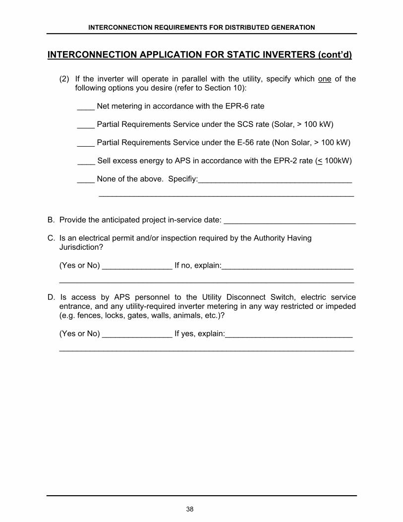
INTERCONNECTION REQUIREMENTS FOR DISTRIBUTED GENERATION
38
INTERCONNECTION APPLICATION FOR STATIC INVERTERS (cont’d)
(2) If the inverter will operate in parallel with the utility, specify which one of the
following options you desire (refer to Section 10):
____ Net metering in accordance with the EPR-6 rate ____ Partial Requirements Service under the SCS rate (Solar, > 100 kW) ____ Partial Requirements Service under the E-56 rate (Non Solar, > 100 kW)
____ Sell excess energy to APS in accordance with the EPR-2 rate (< 100kW)
____ None of the above. Specifiy:___________________________________
__________________________________________________________
B. Provide the anticipated project in-service date: ______________________________ C. Is an electrical permit and/or inspection required by the Authority Having
Jurisdiction? (Yes or No) ________________ If no, explain:______________________________
___________________________________________________________________ D. Is access by APS personnel to the Utility Disconnect Switch, electric service
entrance, and any utility-required inverter metering in any way restricted or impeded (e.g. fences, locks, gates, walls, animals, etc.)? (Yes or No) ________________ If yes, explain:_____________________________
___________________________________________________________________

INTERCONNECTION REQUIREMENTS FOR DISTRIBUTED GENERATION
39
INTERCONNECTION APPLICATION FOR STATIC INVERTERS (cont’d)
SYSTEM OWNER If the GF is owned by a person or entity other than the Customer, complete the following: Name: __________________________ Company: _________________________ Mailing Address:________________________________________________________ Phone: ______________________ E-mail: _______________________________ SYSTEM OPERATOR If the GF is to be operated by a person or entity other than the Customer, complete the following: Name: __________________________ Company: _________________________ Mailing Address:________________________________________________________ Phone: ______________________ E-mail: _______________________________ INTERCONNECTION PROCESS CONTACT INFORMATION If the primary contact for interconnection process is to be coordinated by someone other than the Customer, complete the following: Name: __________________________ Company: _________________________ Mailing Address:________________________________________________________ Phone: ______________________ E-mail: _______________________________ CUSTOMER CERTIFICATION This Application is complete and accurate to the best of my knowledge, and I hereby grant APS permission to coordinate the interconnection process with the person or entity specified above, if completed. APS Customer Name: ___________________________________________________ Signature: ____________________________________________Date: ____________

INTERCONNECTION REQUIREMENTS FOR DISTRIBUTED GENERATION
40
INTERCONNECTION APPLICATION FOR STATIC INVERTERS (cont’d) SUPPLEMENTARY INFORMATION Diagrams specified below are to be specifically prepared for APS’ use, and to be submitted for all static inverter based projects. APS will not accept any copyrighted drawings. These must be site specific regarding the information requested below, without extraneous information. All diagrams are to be professionally drawn, using only black print on white paper; and are not to be in color or shaded. Free hand drawn, photocopies and faxed diagrams will not be accepted by APS. All diagrams must include the project name and street address and include diagram revision numbers and dates.
Upon request, APS will provide Customer with a set of sample diagrams that indicate the general layout, the level of detail, the necessary information, and the required quality of the Customer diagrams for a typical inverter-based system. Standard industry accepted electrical symbols shall be used on the diagrams. The required size for all drawings is 8.5”x11” or 11”x17”. (a) Electrical One-Line Diagram:
Diagram(s) must show all generation sources (eg. photovoltaic panels, wind generator, etc.) and any associated DC electrical components, inverter(s), any combiner panels, metering, Utility Disconnect Switch, as well as the electric service entrance. In addition, the utility meter, connection points of facility loads, and all other associated electrical components must be shown. The electrical ratings of the wire and equipment including all backfed breakers or fuses and any subpanels, must be indicated.
(b) Electrical Three-Line Diagram:
Diagram(s) must show detailed phase wiring of all electrical equipment as specified in the Electrical One-Line Diagram, as well as all neutral, equipment ground and grounding electrode equipment (G.E.C.) conductors and connections.
(c) Plant Location Diagram:
Diagram must show major cross streets and location of facility. Include a North arrow.
(d) Site Plan: Diagram must show the arrangement of the major GF equipment, including the electric service entrance section and utility meter, location of the inverter(s), Utility Disconnect Switch and any lock-boxes, etc. Include building structure location and any walls, fences and gates etc, to clearly indicate unobstructed access to APS equipment, any required special metering and the Utility Disconnect Switch. Include a North arrow.

INTERCONNECTION REQUIREMENTS FOR DISTRIBUTED GENERATION
41
INTERCONNECTION APPLICATION FOR ROTATING MACHINERY
CUSTOMER AND SITE INFORMATION APS Customer Account Holders Name(s)____________________________________ Company Name (if applicable)_____________________________________________ Generating Facility Address_______________________________________________
_____________________________________________________________________
Customer Mailing Address________________________________________________
_____________________________________________________________________
Telephone (day) _________________ E-mail _______________________________ APS Account Number ______________ APS Meter No ________________________ GENERATOR INFORMATION A. Manufacturer ___________________ Model No.___________________________ B. Generator Type (Synchronous, Induction)_________________________________ C. Generator Nameplate Rating
Voltage ___________________ Single or Three Phase___________________ Power Factor _______________ Continuous Power kW___________________ No. of Units ________________ Total System kW_______________________
D. Generator Electrical Characteristics (on the machine base, for above 50 kW) Synchronous Reactance (Xd) ___________________________________ Transient Reactance (X’d) ___________________________________ Subtransient Reactance (X”d) ___________________________________ Stator Resistance (Ra) ___________________________________ Zero Sequence Reactance (X0) ___________________________________ Zero Sequence Resistance (R0) ___________________________________ Negative Sequence Reactance (X2) ___________________________________ Negative Sequence Resistance (R2) ___________________________________

INTERCONNECTION REQUIREMENTS FOR DISTRIBUTED GENERATION
42
INTERCONNECTION APPLICATION FOR ROTATING MACHINERY
(cont’d)
E. Generator Neutral Grounding (for above 300 kW)
Specify whether the generator neutral will be solidly grounded or grounded through a
neutral resistor: ______________________________________________________
If grounded through a neutral resistor, specify the resistance: __________________
PRIME MOVER A. Manufacturer ______________________ Model No. _________________________ B. Fuel Source (Natural Gas, Landfill Gas, etc.) _______________________________ C. Is useful heat recovered from the prime mover (Yes or No) ____________________ D. Is the installation a Qualifying Facility (QF) (Yes or No) _______________________ INTERFACE EQUIPMENT AND PROTECTIVE RELAY INFORMATION (Complete all applicable items; attach a separate sheet if necessary). A. Synchronizer for Synchronous Generator:
Manufacturer _____________________Model No. __________________________ Automatic or Manual Synchronizer_______________________________________
B. Manufacturer’s name and model number for each protective device (refer to section 8) ____________________________________________________________________________________________________________________________________________________________________________________________________________________________________________________________________________
C. Proposed settings (trip setpoint and time) for each protective device (refer to section 8) ____________________________________________________________________________________________________________________________________________________________________________________________________________________________________________________________________________

INTERCONNECTION REQUIREMENTS FOR DISTRIBUTED GENERATION
INTERCONNECTION APPLICATION FOR ROTATING MACHINERY
(cont’d)
PROPOSED OPERATION A. (1) Specify the mode in which the Generator will operate:
Continuous Parallel
Smooth Parallel Transition (normally 5-15 seconds)
Momentary Parallel Transition (normally <10 cycles)
(2) If the Generator will operate in continuous parallel with the utility, specify which
one of the following options you desire:
____ Net metering in accordance with the EPR-6 rate (Q.F.) ____ Partial Requirements Service under the SC-S rate (Solar, > 100 kW) ____ Partial Requirements Service under the E-56 rate (Non Solar, > 100 kW)
____ Sell excess energy to APS in accordance with the EPR-2 rate (≤ 100 kW) ____ None of the above. Specify: ___________________________________
__________________________________________________________
B. Provide the anticipated project in-service date: _____________________________ C. Is an electrical permit and/or inspection required by the Authority Having
Jurisdiction? (Yes or No) ________________ If no, explain:______________________________
___________________________________________________________________ D. Is access by APS personnel to the Utility Disconnect Switch, electric service
entrance, and any utility-required generation metering in any way restricted or impeded (fences, locks, gates, walls, animals, etc.)?
(Yes or No)__________If yes, explain:____________________________________
___________________________________________________________________
43

INTERCONNECTION REQUIREMENTS FOR DISTRIBUTED GENERATION
44
INTERCONNECTION APPLICATION FOR ROTATING MACHINERY (cont’d)
SYSTEM OWNER If the GF is owned by a person or entity other than the Customer, complete the following: Name: __________________________ Company: _________________________ Mailing Address: ________________________________________________________ Phone: ______________________ E-mail: _______________________________ SYSTEM OPERATOR If the GF is to be operated by a person or entity other than the Customer, complete the following: Name: __________________________ Company: _________________________ Mailing Address: ________________________________________________________ Phone: ______________________ E-mail: _______________________________ INTERCONNECTION PROCESS CONTACT INFORMATION If the primary contact for interconnection process is to be coordinated by someone other than the Customer, complete the following: Name: __________________________ Company: _________________________ Mailing Address: ________________________________________________________ Phone: ______________________ E-mail: _______________________________ CUSTOMER CERTIFICATION This Application is complete and accurate to the best of my knowledge, and I hereby grant APS permission to coordinate the interconnection process with the person or entity specified above, if completed. APS Customer Name:____________________________________________________ Signature: ____________________________________________Date: ____________

INTERCONNECTION REQUIREMENTS FOR DISTRIBUTED GENERATION
45
INTERCONNECTION APPLICATION FOR ROTATING MACHINERY
(cont’d) SUPPLEMENTARY INFORMATION Diagrams and information specified below are to be specifically prepared for APS’ use, and to be submitted for all rotating machinery based projects. APS will not accept any copyrighted drawings. These must be site specific regarding the information requested below, without extraneous information. All diagrams are to be professionally drawn, using only black print on white paper, and our not to be color or shaded. Free hand drawn, photocopies and faxed diagrams will not be accepted by APS. All diagrams must include the project name and street address as well as diagram revision numbers and dates. Standard industry accepted electrical symbols shall be used on the diagrams. The required size for all drawings is 8.5”x11” or 11”x17”. (a) Electrical One-Line Diagram:
Diagram(s) must show generators and all major associated electrical components including protective relaying, any interlocks and control functions, as well as the electric service entrance, utility meter, connection points of facility loads, any transformers, generator metering, and Utility Disconnect Switch. The electrical ratings of the equipment shall be shown.
(b) AC & DC Control Schematics:
Diagram(s) must show the detailed phase wiring of all electrical equipment as specified above for the Electrical One-Line Diagram, including protective relaying, associated instrument transformers, and control functions. Include control power source and all associated AC and DC connections.
(c) Plant Location Diagram:
Diagram must show major cross streets and location of facility. Include a North arrow.
(d) Site Plan:
Diagram must show the arrangement of the major GF equipment, including the electric service entrance section and utility meter, location of generator(s), interface equipment, Utility Disconnect Switch and location of any lock-boxes, etc. Include building structure location and any walls, fences and gates etc, to clearly indicate unobstructed access to APS equipment and Disconnect Switch. Include a North arrow.
(e) Relay Setting Sheet(s):
Setting sheet(s) for the APS-required minimum protective relay functions must show the trip setpoints and times. Settings may be provided after the initial APS review, once the final system configuration has been determined.