Interconnection of Distributed Generation and Net-Metering in MA

Distributed Generation Systems: Technical Interconnection
Requirements
Revision 1 July 2019

2
Distributed Generation Systems: Technical Interconnection Requirements – July 2019
Table of Contents
1 INTRODUCTION ............................................................................................................................................... 3
1.1 DISCLAIMERS ...................................................................................................................................................... 4 1.2 REVISION HISTORY ............................................................................................................................................. 4
2 SUMMERLAND DISTRIBUTION SYSTEM .................................................................................................... 5
3 DISTRIBUTED GENERATION REQUIREMENTS ......................................................................................... 6
3.1 WHAT QUALIFIES AS A DISTRIBUTED GENERATION SYSTEM? .......................................................................... 6 3.2 REQUIREMENTS .................................................................................................................................................. 6
3.2.1 Equipment ..................................................................................................................................................... 6 3.2.2 Protection ...................................................................................................................................................... 7 3.2.3 Power Quality ............................................................................................................................................... 7 3.2.4 Commissioning & Operation ...................................................................................................................... 7
APPENDIX A: DEFINITIONS AND REFERENCES ............................................................................................... 9
A.1 DEFINITIONS AND ACRONYMS ............................................................................................................................ 9 A.2 REFERENCES .................................................................................................................................................... 10
APPENDIX B: FIGURES AND SINGLE LINE DIAGRAMS ................................................................................ 11
APPENDIX C: TECHNICAL TABLES ................................................................................................................... 13

3
Distributed Generation Systems: Technical Interconnection Requirements – July 2019
1 Introduction
The District of Summerland provides a means for distribution-connected customers to connect a small energy source to the Summerland Distribution System to offset their load and participate in the Distributed Generation (DG) program. This document contains the technical interconnection requirements for connecting small generators to Summerland’s Distribution System. The total generation must have an aggregate nameplate rating of 30 kW or less. DG Systems with generation over this limit will be assessed on a case by case basis.
In this document, customers who are connecting a generator are referred to as Distributed System owners. DG System owners must obtain approval from Summerland to interconnect their generator to the Summerland system. The requirements outlined in this document are intended to:
• ensure the safety of the customer, Summerland personnel, and the public; • maintain reliability and power quality on the Distribution System; and • establish the range of operating conditions that DG systems will encounter.
The aggregate nameplate rating of the generators at the Point of Common Couplings shall not exceed the capacity of the customer’s existing electrical service. The customer may upgrade their electrical service to meet this requirement, at their cost, subject to approval by the Summerland Electrical Utility.
How to use this document
1) Confirm the generator can operate within the Distribution System parameters in Section 2; 2) Refer to the interconnection requirements in Section 3

4
Distributed Generation Systems: Technical Interconnection Requirements – July 2019
1.1 Disclaimers The information contained in this document is subject to future revisions. Important notes of limitations include:
• this document is not a replacement for electrical codes or other applicable standards;
• this document is not intended or provided by Summerland as a design specification or as an instruction manual for the DG System owner, employees or agents, and the document shall not be used by the proponent, their employees, or agents for those purposes. Persons using this information do so at no risk to Summerland and they rely solely upon themselves to ensure that their use of all or part of this document is appropriate in their particular circumstance;
• the DG System owner, employees, or agents recognize that they are, at all times, solely responsible for the generation system design, construction, and operation. Summerland, its employees or agents shall not be or become the agent of the proponent in any manner howsoever arising; and
• the advice by Summerland, its employees or agents, that the generation system design or equipment meets certain Summerland requirements does not mean, expressly or by implication, that all or any of the requirements of the law or good Engineering practice have been met by the owner, and such judgement shall not be construed by the owner or others as an endorsement of the design or as a warranty by Summerland, its employees and agents, of the design or equipment, or any part thereof.
1.2 Revision History
Date Revision Comments July 2019 1 Original

5
Distributed Generation Systems: Technical Interconnection Requirements – July 2019
2 Summerland Distribution System
Under normal and emergency conditions, Summerland’s Distribution System exhibits a range of electrical parameter fluctuations. They are summarized in Table 1. The DG System owner must ensure that the DG System can operate satisfactorily under these conditions and protect itself against excursions outside of these parameter ranges.
Table 1 - Distribution System Parameters
Parameter Typical Value or Reference Notes and Standards Referencing
System
60 Hertz (59.7 Hz to 60.2 Hz) Refer to Clause 5.2.2 of CSA C22.2 No. 257-06.
Service Entrance Voltage
Normal Operating Conditions: +4.2 / -8.3 % Extreme Operating Conditions: +6 / -11.5 %
For 1-Phase 120/240 V, 347/600 V Y, 240 V Delta and 480 V Delta.
Harmonics
Maximum Voltage Total Harmonic Distortion (THD): < 8% Long Term THD (≥10 min) < 11% Short Term THD (≤3 sec)
Refer to Clause 4.3 of CAN/CSA C61000-2-2.
Voltage Flicker
Compatibility levels for severity indices: short-term (10 min), Pst = 1.0 long-term (2 hour), Plt = 0.8
Compatibility levels (95 % weekly probability) for flicker in LV systems; 99 % weekly probability values must fall within 1.3× 95 % levels. Refer to Table 1 of CAN/CSA- C61000-3-7.
Rapid Voltage
Fluctuation
Number of Voltage Changes (n) Change (%)
n ≤ 4/day 5-6 n ≤ 2/hour & > 4/day 4 2 < n ≤ 10/hour 3
Rapid voltage fluctuation on the MV system can become a problem when induction generators are started; voltage rise and fall constitutes 2 changes (n = 2), and higher values may be permissible under abnormal system conditions. Refer to Table 6 of CAN/CSA-C61000-3-7.
Voltage Unbalance
When averaged over 10 min, under normal conditions, Summerland targets: VU of <2% for 95% of the time and VU of <3% for 99.9% of the time.
The voltage unbalance factor (VU) is approximated by dividing the greatest phase deviation from the mean voltage by the mean voltage. Refer to CAN/CSA-C61000- 4-30-04 for use of symmetrical component ratios for calculation of voltage imbalance.
DGs interconnecting with the Distribution System must not create objectionable voltage unbalance. Refer to Clause 7.2.5 of CAN/CSA-C22.3 No. 9-08.
Fault Levels These vary based on circuit configuration and project location.
System Grounding
3-phase, 4-wire multi-grounded
Fault and Line Clearing
Summerland may use automatic reclosing (re-energizing of the line) on circuit breakers which have been tripped for faults.
The DG System must cease delivering power within 0.16 seconds after de-energization of the Distribution System (unless explicitly accepted by Summerland) and not re- energize or synchronize until the Distribution System is Stable. 5 minutes after power restoration.

6
Distributed Generation Systems: Technical Interconnection Requirements – July 2019
3 Distributed Generation Requirements
3.1 What Qualifies as a Distributed Generation System? For the purposes of this document, a Distributed Generation System shall meet all of the following:
• be an inverter-based system installed in accordance with Canadian Electrical Code (CEC) Part I and certified to the requirements of CSA C22.2 No. 107.1-01 for utility interconnection; and
• has an aggregate nameplate rating of 30 kVA at 0.9 power factor at the Point of Common Coupling; and
• has revenue metering that is 200A or less and single phase; and • use as an energy source a low-carbon or renewable resource, such as water power,
solar energy, wind energy, geothermal energy, wood residue energy, energy from organic waste, and other energy sources approved by the General Manager, Electrical Utility
3.2 Requirements This section provides the technical requirements to be met by any DG System that will be interconnected to Summerland’s Distribution System.
3.2.1 Equipment General As applicable, DG Systems shall meet:
• CEC Part I (see Sections 50, 64 & 84) • CAN/CSA-C22.2 No. 257-06 • CAN/CSA-C22.3 No. 9-08 • CSA C22.2 No. 107.1-01
Point of Common Coupling The Point of Common Coupling (PCC) is the point where Summerland’s Distribution System and the DG System owner’s installation interconnect. This is typically at the weatherhead (for overhead service connections) or at the revenue meter base (for underground service connections). Summerland is responsible for design, construction, maintenance, and operation of all facilities on the Summerland side of the PCC. The DG System owner shall be responsible for design, construction, inspection, maintenance, and operation of all facilities on their side of the PCC. DG System Disconnect Means All generators interconnected with the Distribution System require a means to safely disconnect them and ensure isolation in accordance with CEC Part I, Section 84. Summerland’s Electrical Utility does not specify the physical location of the customer’s means of disconnection. As per CEC Part I, Section 84-030, the DG System owner shall install a warning label at the

7
Distributed Generation Systems: Technical Interconnection Requirements – July 2019
revenue meter location and at the Disconnect Means, and a single-line, permanent, legible diagram of the interconnected system shall be installed in a conspicuous place at the disconnecting means.
3.2.2 Protection The generator protection shall be in accordance with CEC Part I and Appendix C: Technical Tables. Anti-islanding The anti-islanding requirements of CAN/CSA-C22.2 No. 257-06 and CSA C22.2 No. 107.1-01 requires the inverter to cease energizing the Distribution System within 0.1 seconds upon loss of the utility (Summerland) supply. This provides for the safety of electrical workers and the public. Grid-dependent inverters are designed to only energize when the utility (Summerland) supply is present, but grid-interactive inverters can also operate in stand-alone (sometimes called off-grid) mode and must be verified to be in grid-dependent mode. A grid-interactive inverter may contain the internal disconnects and transfer switch to ensure isolation from the Summerland Distribution System while still supplying an essential load panel. See Appendix A: Definitions and References for more detailed definitions.
3.2.3 Power Quality Inverters certified to the requirements of CSA C22.2 No. 107.1-01 for utility interconnection meet the power quality requirements for connection to the Distribution System.
3.2.4 Commissioning & Operation General The DG System owner is required to confirm that all requirements of the manufacturer are met, and that the DG System installation meets the requirements of this document and CSA C22.2 No. 257-06. If requested, the DG System owner will provide to Summerland a list of step-by-step energizing and commissioning procedures prior to DG System commissioning. The DG System owner shall retain a complete set of manuals, installation drawings, permits, inspection and verification test reports and make them available to Summerland if requested. Testing & Commissioning Prior to completion of DG System commissioning, or whenever the generator system is modified, a verification test shall be performed as recommended by the equipment manufacturer and required by CAN/CSA-C22.2 No. 257-06 Section 7. Testing of the DG System shall include procedures to functionally test all protective elements including verification of inverter trip timing. Maintenance & Operation In addition to keeping all equipment well maintained and functional, the DG System owner shall verify the generator’s interconnection protective functions according to the manufacturer’s recommended schedule, or at least once a year as required by CAN/CSA-C22.2 No. 257-06 Section 8. If there is no manufacturer’s recommendation, operation of the disconnecting means and verifying that the inverter system automatically ceases to energize is an acceptable method

8
Distributed Generation Systems: Technical Interconnection Requirements – July 2019
of verification. Maintenance records shall be maintained by the owner. Failure to perform and record maintenance can result in disconnection of the DG System. The DG System owner must notify Summerland of any subsequent changes to equipment, by submitting a revised Interconnection Application form, to confirm that the proposed equipment modification still meets the requirements to qualify as a DG System.

9
Distributed Generation Systems: Technical Interconnection Requirements – July 2019
Appendix A: Definitions and References
A.1 Definitions and Acronyms Canadian Standards Association (CSA): An accredited standards development organisation within Canada. Disconnecting Means: A device, group of devices, or other means whereby the conductors of a circuit can be disconnected from their source of supply. Distributed Generation (DG): Electric power generation facilities connected to the Summerland Distribution System through the Point of Common Coupling. Distributed Generation System Owner (DG System Owner): Any legal entity responsible for the DG System interconnected to the Distribution System for the purpose of generating electric power. Distributed Generation System (DG System): The aggregate of the Distributed Generation electricity generator, inverter(s), control system(s), sensing device(s) or function(s), and protection devices and functions to the customer service entrance disconnect switch. Distribution System: That part of the Summerland system that operates at 34,500 V or less and distributes electric power between Summerland substations and Points of Common Coupling. Generator: Equipment that produces electric power. (Note: The inverter is recognized as being a “generator” from the perspective of the Distribution System) Interconnection: The result of the process of electrically connecting a Distributed Generation System in parallel with the Distribution System. Interconnection System: The collection of all interconnection equipment, including the utility interconnected inverter, and functions, taken as a group, used to interconnect a Distributed Generator to the rest of the customer's facilities. The interconnection system can be internal to the Distributed Generation System (see Figure B.1). Inverter: A power electronic device, which converts DC power into AC power.
Grid-Tied Inverter (also known as Grid-connected Inverter): An inverter that is able to operate in grid-parallel mode (in which an inverter operates in parallel with the Distribution System and contains provision for synchronising its voltage, phase, and frequency to the Distribution System). Grid-Dependent Inverter: A type of Grid-Tied Inverter that operates only in grid-dependent mode (in which an inverter operating in grid-parallel mode depends on Summerland’s distribution facility to initiate and maintain its operation). As per CSA C22.2 No. 107.1-01, Section 15.3.5.4, a Grid-Dependent Inverter must cease to deliver power within 2 seconds of loss of the grid. Grid-Interactive Inverter: A type of Grid-Tied Inverter that is able to operate in both stand-alone mode (in which an inverter operates in isolation from Summerland’s distribution facility, and generates its own voltage, phase, and frequency conditions (i.e. self-commutated) and grid-parallel mode (see “Grid-Tied Inverter” definition) according to the availability of Summerland’s distribution facility.

10
Distributed Generation Systems: Technical Interconnection Requirements – July 2019
Island: A condition in which a portion of the Distribution System is energized by one or more Distributed Generation Systems while that portion of the Distribution System is electrically separated from the rest of the Distribution System. Parallel Operation: The simultaneous energization of a Point of Common Coupling by the Distribution System and the Distributed Generation System. Point of Common Coupling (PCC): The point where Summerland’s Distribution System and the DG System owner’s installation interconnect. Protection Scheme (or protection system): The protection functions, including associated sensors, relaying, and power supplies, intended to protect the distribution system or interconnection equipment. Stable or Stabilized: Refers to the Distribution System voltage returning to the normal range of level and frequency for five minutes or a time as co-ordinated with Summerland, following a disturbance. Total Harmonic Distortion (THD): A measure of the total sum of squares of harmonic frequency signals compared to a fundamental frequency signal. Voltage Flicker: A variation in Distribution System voltage large enough to be perceived as an objectionable change of intensity from a light bulb. Wires Owner (Summerland): The legal entity responsible for the Distribution System within the District of Summerland. A.2 References
1) CAN/CSA-C22.2 No. 257-06, “Interconnecting Inverted-Based Micro-Distributed Resources to
Distribution Systems.” March 2006. 2) CAN/CSA-C22.3 No. 9-08, “Interconnection of Distributed Resources and Electricity Supply
Systems.” June 2008. 3) CAN/CSA-C61000-2-2, “Electromagnetic Compatibility (EMC) – Part 2-2: Environment –
Compatibility Levels for Low-Frequency Conducted Disturbances and Signalling in Public Low- Voltage Power Supply Systems.” November 2004.
4) CAN/CSA-C61000-3-7, “Electromagnetic Compatibility (EMC) – Part 3-7: Limits – Assessment of emission limits for the connection of fluctuating installations to MV, HV and EHV power systems.” February 2009.
5) CSA C22.1-12, “Canadian Electrical Code Part 1, Safety Standards for Electrical Installations, 22nd Edition” (With BC Amendments). January 2012. (CEC Part I).
6) CSA C22.2 No. 0-10, “General Requirements – Canadian Electrical Code, Part II, 10th Edition.” September 2010. (CEC Part II)
7) CSA CAN-3-C235-83, “Preferred Voltage Levels for AC Systems, 0 to 50,000 Volts, Canadian Utility Distribution Systems.” Reaffirmed 2010.
8) CSA Standard C22.2 No. 107.1-01, “General Use Power Supplies.” September 2001. 9) IEEE 100, “The Authoritative Dictionary of IEEE Standards Terms, Seventh Edition.” December
2000. 10) IEEE Std C37.90-2005, “IEEE Standard for Relays and Relay systems Associated with Electric
Power Apparatus.” January 2006.

11
Distributed Generation Systems: Technical Interconnection Requirements – July 2019
Appendix B: Figures and Single Line Diagrams
Figure B.1 – Relationship between DG System and Other Interconnection Terms (Source: Adapted From CAN/CSA-C22.2 No. 257-06 Figure 1)
PCC Summerland Distribution
Point of DG System Connection
DG System
DG’s Facility Boundary
DG’s Local Loads
DG
Interconnection System (may be internal to DG)
DG

12
Distributed Generation Systems: Technical Interconnection Requirements – July 2019
Notes:
Figure B.2 – Single Line Diagram of Typical Inverter Based Generator (Source: Adapted from CAN/CSA-C22.3 No. 257-06 B-1
1 This is a warning notice required by Clause 84-030 of the CEC Part I. Summerland requires that the notice should be a permanent label suitable for outdoor conditions, with black letters on a white background, 7.5 cm x 2.5 cm and mounted to the revenue meter base or within 0.3m of the revenue meter.
2 Protection functions shown shall be internal to the inverter.
13
Distributed Generation Systems: Technical Interconnection Requirements – July 2019
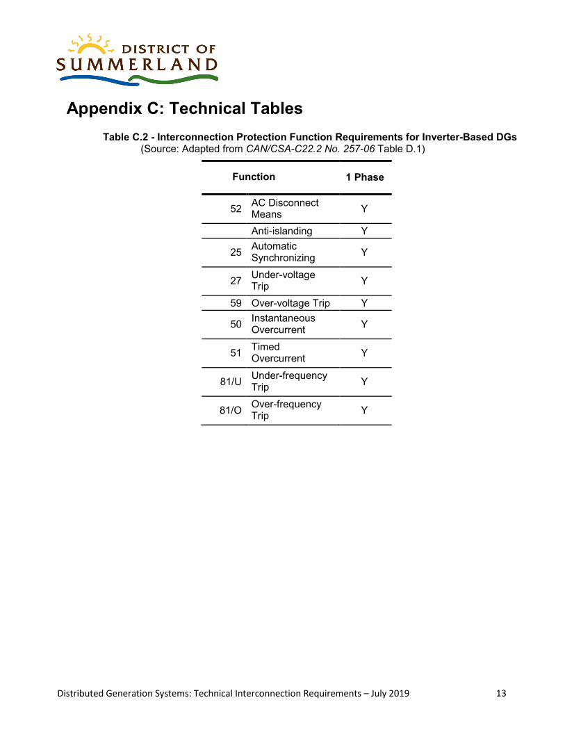
Appendix C: Technical Tables
Table C.2 - Interconnection Protection Function Requirements for Inverter-Based DGs (Source: Adapted from CAN/CSA-C22.2 No. 257-06 Table D.1)
Function 1 Phase
52 AC Disconnect Means Y
Anti-islanding Y
25 Automatic Synchronizing Y
27 Under-voltage Trip Y
59 Over-voltage Trip Y
50 Instantaneous Overcurrent Y
51 Timed Overcurrent Y
81/U Under-frequency Trip Y
81/O Over-frequency Trip Y