
DG Interconnection and Net Metering Seminar · Distributed Generation (DG) – Distributed...
94
DG Interconnection and Net Metering Seminar April 25, 2013 Worcester, MA Co-hosted by:
Transcript of DG Interconnection and Net Metering Seminar · Distributed Generation (DG) – Distributed...
DG Interconnection and
Net Metering Seminar
April 25, 2013 Worcester, MA
Co-hosted by:
2
Logistics & Introductions
• Facilities
– Emergency exits
– Restrooms
– Designated smoking area
• Guests and presenters
– DPU / DOER / Mass CEC
– MA Utilities: National Grid / NSTAR / Unitil / WMECO

DOER Welcome Slide
DOER’s role in Distributed Generation:
o Assisting with incentives for clean energy
• Portfolio Standards (RPS/SRECs/APS)
• Net Metering
o Increasing awareness about policies
• Interconnection
• Rates
• System Planning / Service Quality
o Advising on new policies
• Streamlining Interconnection
• Hands-on assistance with challenging projects
3
4
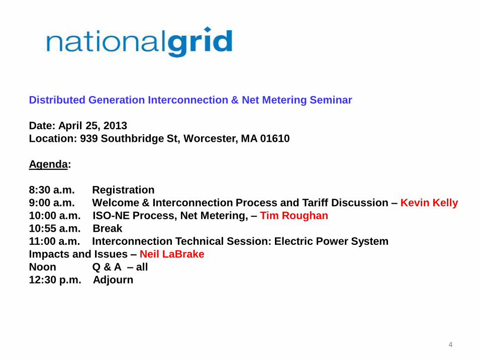
Distributed Generation Interconnection & Net Metering Seminar
Date: April 25, 2013
Location: 939 Southbridge St, Worcester, MA 01610
Agenda:
8:30 a.m. Registration
9:00 a.m. Welcome & Interconnection Process and Tariff Discussion – Kevin Kelly
10:00 a.m. ISO-NE Process, Net Metering, – Tim Roughan
10:55 a.m. Break
11:00 a.m. Interconnection Technical Session: Electric Power System
Impacts and Issues – Neil LaBrake
Noon Q & A – all
12:30 p.m. Adjourn
Safety Moment
• This morning’s session provides a great safety moment. – All the benefits derived from Distributed
Generation quickly lose their value if someone is injured as a result of an improper interconnection.
Key Terms
Distributed Generation (DG) – Distributed generation is any electricity generating technology installed by a customer or independent electricity producer that is connected to run in parallel with grid power at the distribution system level of the electric grid. Interconnection- Electricity customers seeking to operate DG in parallel with (or at the same time as receiving) grid power must follow the interconnection process of electric utilities (also known as the “Interconnection Tariff”). DPU- The MA Department of Public Utilities regulates the investor-owned utilities in the Commonwealth. ISO-NE – The Independent System Operator of New England is the grid operator of the electric transmission system (as opposed to the distribution system regulated by the DPU). Tariff- The rate applied by the electric utility as a result of DPU regulation. It is a standard to ensure that utilities fulfill their regulated obligation to serve and so that all customers are provided equal/fair treatment.
6

Distributed Generation and the Electric Grid
Distributed Generation (DG) Systems are becoming more popular due to more aggressive incentives for clean energy such as net metering, RPS/APS, etc. DG Systems are generally:
• much smaller in MW rating than centralized power generation
• tied to the distribution system of the grid (rather than the transmission side)
Two Types of grid-connected DG • Behind Meter: DG system is used to partially or fully supply an on-site load. Any unused electricity is exported to the distribution system (most projects follow the state interconnection process; there are exceptions that follow the ISO process).
• Direct Connect: DG system does not supply an on-site load, and is connected directly to the distribution system
7
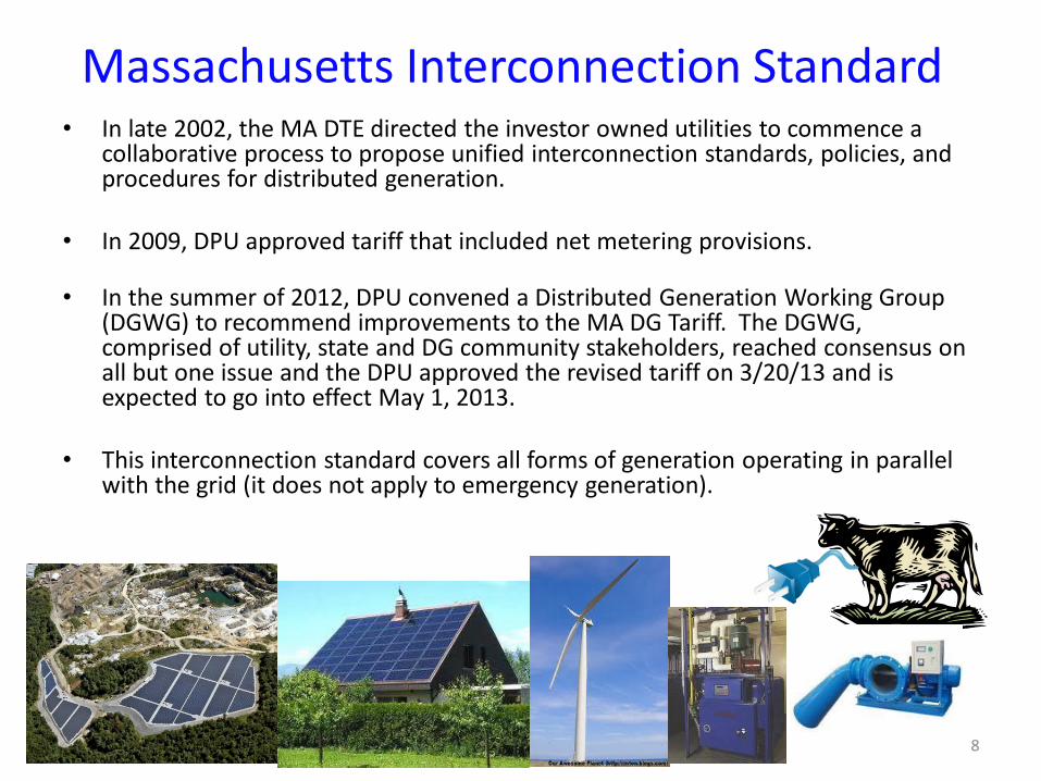
Massachusetts Interconnection Standard • In late 2002, the MA DTE directed the investor owned utilities to commence a
collaborative process to propose unified interconnection standards, policies, and procedures for distributed generation.
• In 2009, DPU approved tariff that included net metering provisions.
• In the summer of 2012, DPU convened a Distributed Generation Working Group (DGWG) to recommend improvements to the MA DG Tariff. The DGWG, comprised of utility, state and DG community stakeholders, reached consensus on all but one issue and the DPU approved the revised tariff on 3/20/13 and is expected to go into effect May 1, 2013.
• This interconnection standard covers all forms of generation operating in parallel with the grid (it does not apply to emergency generation).
8

What is the Interconnection Process?
• Process of getting an interconnection agreement from your local utility (or distribution company) to connect a distributed generation system to their distribution system.
• This process is used by the four investor owned utilities (IOU) in Massachusetts (NSTAR, National Grid, Unitil and Western Mass Electric)
• Municipally-owned utilities are not required to follow this process, and may follow a different criteria.
• The process is used to make sure interconnecting DG systems are integrated into the distribution system responsibly with respect to impacts on reliability, power quality and safety
9

Importance of the Interconnection Process
• Following the interconnection process is important because a DG system changes the one-way power flow from the utility to customer, which can present dangers to utility workers if proper equipment is not installed
• While robust and capable of handling minor disturbances, the quality of grid power is extremely important. The interconnection process ensures the DG meets safety, reliability, & power quality requirements with regard to: • Islanding • Transient Voltage Conditions • Noise and Harmonics • Frequency • Voltage Level • Machine Reactive Capability
• It is essential that each interconnection get an interconnection agreement
with the utility before installing any generation. You are proceeding at your own risk if you choose to install a system without utility approval.
10

11
Everything starts with the Application • A complete complex application package includes:
– All appropriate sections of 4-page application completely filled out. Customer will likely need assistance from vendor/engineer.
– Copy of Pre-Application Report* – Application fee $4.50*/KW ($300 minimum and $7,500* maximum). This fee
covers the initial review. (Proposed change in 2012 raises these costs) – Stamped electric one-line diagram, preferably showing relay controls (one
copy) (Stamped by Massachusetts Electrical PE) – Site diagram (one copy) – One copy of any supplemental information (if electronic – single copy
acceptable) – Identify electric customer and owner of proposed generation – Schedule Z if planning to Net Meter
• Errors or problems with application will slow down the process and “stop the clock”
• Send Electronic copy of all documents preferred if possible – Easier to distribute, saves paper, and is faster. However, submit first page of application with application fee.
• *Proposed in filed compliance DG tariff.

• Applies to: • Single phase customers with Listed single-phase inverter based systems
15kW (was previously 10 kW) or less on a single phase service on a radial feed
• Three phase customers with listed three-phase inverter based systems 25kW or less on a three phase service on a radial feed. • Listed inverters:
• Comply with current IEEE 1547 Standards • Have nationally recognized test lab results
• Does allow an increase in time for review if screen 5 is not met • Proposed project is not compatible with the existing service at the
site • 20 days versus 15 for the review of screens
• Does not Apply to:
• Non-listed inverters or other generators (induction / synchronous / asynchronous)
• Aggregate generation capacity of listed inverters that exceed the above-mentioned limits
Simplified Review Path
12
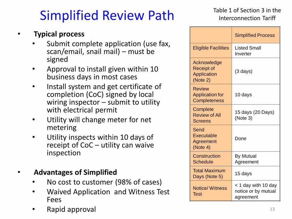
• Typical process • Submit complete application (use fax,
scan/email, snail mail) – must be signed
• Approval to install given within 10 business days in most cases
• Install system and get certificate of completion (CoC) signed by local wiring inspector – submit to utility with electrical permit
• Utility will change meter for net metering
• Utility inspects within 10 days of receipt of CoC – utility can waive inspection
• Advantages of Simplified • No cost to customer (98% of cases) • Waived Application and Witness Test
Fees • Rapid approval
Table 1 of Section 3 in the Interconnection Tariff Simplified Review Path
13
Simplified Process
Eligible Facilities Listed Small
Inverter
Acknowledge
Receipt of
Application
(Note 2)
(3 days)
Review
Application for
Completeness
10 days
Complete
Review of All
Screens
15 days (20 Days)
(Note 3)
Send
Executable
Agreement
(Note 4)
Done
Construction
Schedule
By Mutual
Agreement
Total Maximum
Days (Note 5) 15 days
Notice/ Witness
Test
< 1 day with 10 day
notice or by mutual
agreement

• Applies to: • Single phase customers with listed single-phase inverter
based systems >15 kW on a radial feed • Three phase customers with listed three-phase inverter
based systems >25kW on a radial feed. • Maximum size is based on review of screens
• Does not Apply to: • Non-listed inverters or other generators (induction /
synchronous / asynchronous) • Aggregate generation capacity of listed inverters that exceed
the above-mentioned limits
Expedited Review Path
14

Expedited Review Path • Typically little or no (utility) system
modifications required. If meter only – usually no charges passed to customer
• Application fee plus any Supplemental Review charges up to 30 hours of engineering time @ $150/hr (if needed)
• Relay control system must be well defined to make supplemental review easier.
• Witness test fee of up to $300 plus travel is required.
Table 1 of Section 3 in the Interconnection Tariff
15
Expedited
Eligible Facilities Listed DG
Acknowledge
Receipt of
Application
(Note 2)
(3 days)
Review Application
for Completeness 10 days
Complete Review of
All Screens 25 days
Complete
Supplemental
Review (if needed)
(Note 3)
20 days or Standard Process
Send Executable
Agreement (Note 4) 10 days
Construction
Schedule By Mutual Agreement
Total Maximum
Days (Note 5)
40/60 days
(Note 6)
Notice/ Witness Test < 1 day with 10 day notice
or by mutual agreement

16
Supplemental Review
• If one or more Screens are not passed, the Company will provide a Supplemental Review Agreement.
• Threshold is whether project is less than 67% of minimum load on the feeder – Then other screens review voltage quality , reliability and safety to reduce the potential
need for impact studies. – DPU order allowed for the 67% screen, but requires utilities to document how the use of
a 100% screen would change the screening process
• Customer signs agreement and pays fee for additional engineering time (max fee is
now $4,500).
• The Supplemental Review may be able to determine what impacts the generation system will have and what (if any) modifications are required. If so - an interconnection agreement will be sent to customer detailing: – System modification requirements, reasoning, and costs for these modifications – Specifics on protection requirements as necessary
• If Supplemental Review cannot determine requirements, an Impact Study
Agreement (or equal) will be sent to the customer. (You shift to the Standard Process.)
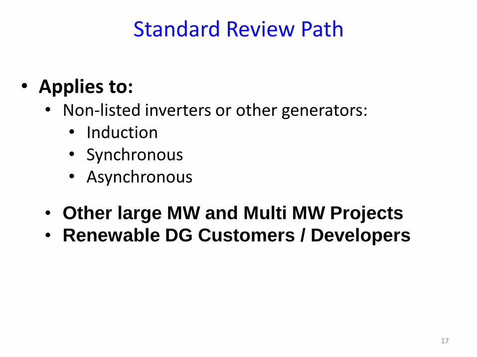
• Applies to: • Non-listed inverters or other generators:
• Induction • Synchronous • Asynchronous
• Other large MW and Multi MW Projects
• Renewable DG Customers / Developers
Standard Review Path
17
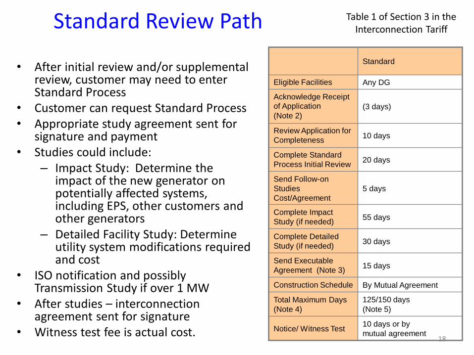
Standard Review Path Table 1 of Section 3 in the Interconnection Tariff
• After initial review and/or supplemental
review, customer may need to enter Standard Process
• Customer can request Standard Process • Appropriate study agreement sent for
signature and payment • Studies could include:
– Impact Study: Determine the impact of the new generator on potentially affected systems, including EPS, other customers and other generators
– Detailed Facility Study: Determine utility system modifications required and cost
• ISO notification and possibly Transmission Study if over 1 MW
• After studies – interconnection agreement sent for signature
• Witness test fee is actual cost. 18
Standard
Eligible Facilities Any DG
Acknowledge Receipt
of Application
(Note 2) (3 days)
Review Application for
Completeness 10 days
Complete Standard
Process Initial Review 20 days
Send Follow-on
Studies
Cost/Agreement
5 days
Complete Impact
Study (if needed) 55 days
Complete Detailed
Study (if needed) 30 days
Send Executable
Agreement (Note 3) 15 days
Construction Schedule By Mutual Agreement
Total Maximum Days
(Note 4)
125/150 days
(Note 5)
Notice/ Witness Test 10 days or by
mutual agreement

19
MA – Revised Interconnection Tariff • The DPU approved Tariff includes changes relating to the existing application
process, reports, fees, screening, and study and construction timelines, some of which are more particularly described below.
• Hoping approval of compliance tariffs on May 1st. New tariff not in effect until approval of compliance tariffs
• Application fees have been modified to reflect increased costs – Minimum $300, maximum $7,500, $4.50 per kW – DPU has opened a new docket to review tariff costs
• New pre-application report showing existing system where project is proposed – Required for projects > 500 kWs, optional for smaller
• Customers can request an ISA after impact study is completed
– If they elect this, our construction timeline estimate must include time to conduct the necessary detailed study prior to construction
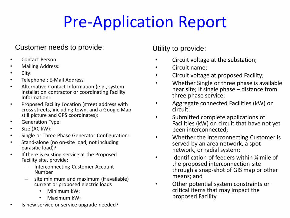
Pre-Application Report
• Contact Person: • Mailing Address: • City: • Telephone ; E-Mail Address • Alternative Contact Information (e.g., system
installation contractor or coordinating Facility Information:
• Proposed Facility Location (street address with cross streets, including town, and a Google Map still picture and GPS coordinates):
• Generation Type: • Size (AC kW): • Single or Three Phase Generator Configuration: • Stand-alone (no on-site load, not including
parasitic load)? • If there is existing service at the Proposed
Facility site, provide: – Interconnecting Customer Account
Number – site minimum and maximum (if available)
current or proposed electric loads • Minimum kW: • Maximum kW:
• Is new service or service upgrade needed?
• Circuit voltage at the substation; • Circuit name; • Circuit voltage at proposed Facility; • Whether Single or three phase is available
near site; If single phase – distance from three phase service;
• Aggregate connected Facilities (kW) on circuit;
• Submitted complete applications of Facilities (kW) on circuit that have not yet been interconnected;
• Whether the Interconnecting Customer is served by an area network, a spot network, or radial system;
• Identification of feeders within ¼ mile of the proposed interconnection site through a snap-shot of GIS map or other means; and
• Other potential system constraints or critical items that may impact the proposed Facility.
Customer needs to provide: Utility to provide:
21
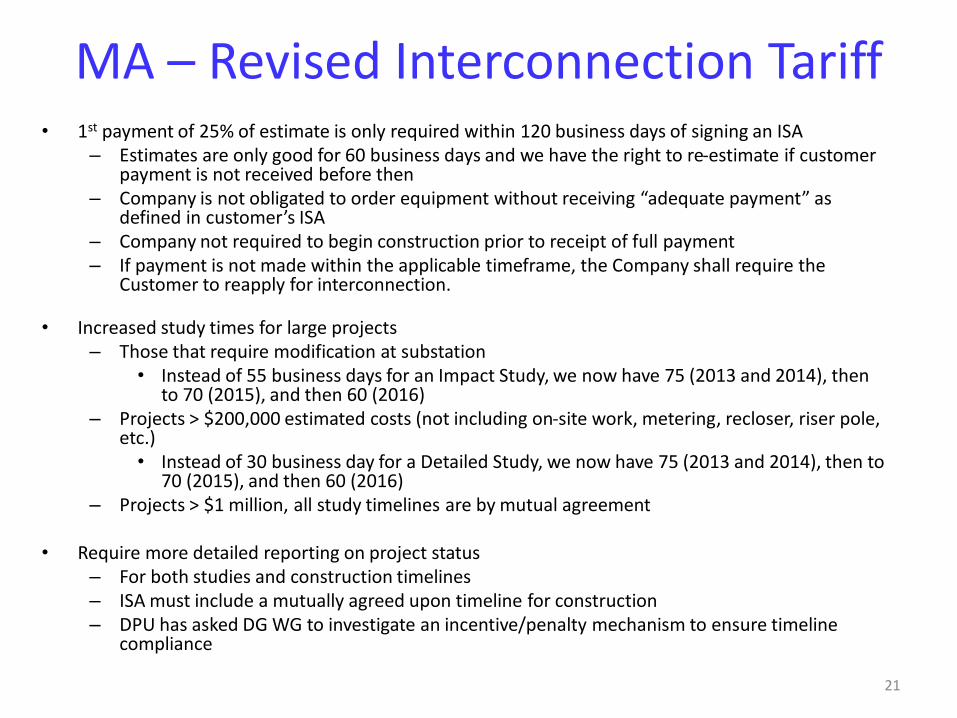
MA – Revised Interconnection Tariff
• 1st payment of 25% of estimate is only required within 120 business days of signing an ISA – Estimates are only good for 60 business days and we have the right to re-estimate if customer
payment is not received before then – Company is not obligated to order equipment without receiving “adequate payment” as
defined in customer’s ISA – Company not required to begin construction prior to receipt of full payment – If payment is not made within the applicable timeframe, the Company shall require the
Customer to reapply for interconnection.
• Increased study times for large projects – Those that require modification at substation
• Instead of 55 business days for an Impact Study, we now have 75 (2013 and 2014), then to 70 (2015), and then 60 (2016)
– Projects > $200,000 estimated costs (not including on-site work, metering, recloser, riser pole, etc.)
• Instead of 30 business day for a Detailed Study, we now have 75 (2013 and 2014), then to 70 (2015), and then 60 (2016)
– Projects > $1 million, all study timelines are by mutual agreement
• Require more detailed reporting on project status – For both studies and construction timelines – ISA must include a mutually agreed upon timeline for construction – DPU has asked DG WG to investigate an incentive/penalty mechanism to ensure timeline
compliance
22
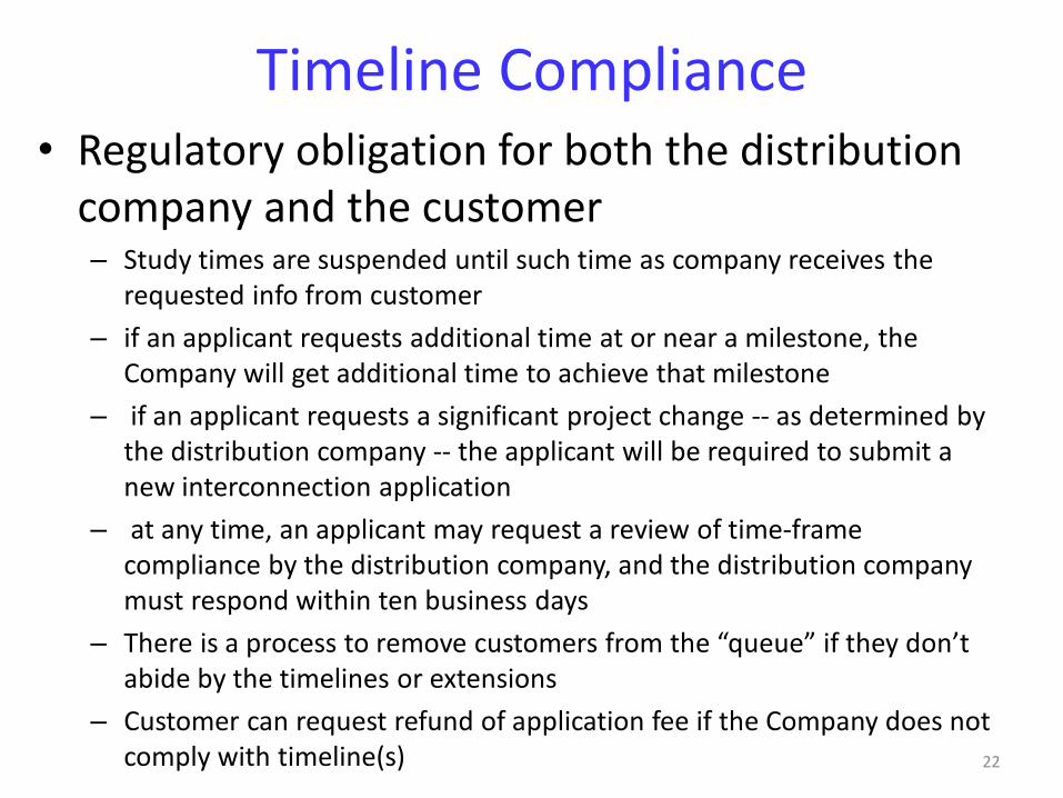
Timeline Compliance • Regulatory obligation for both the distribution
company and the customer – Study times are suspended until such time as company receives the
requested info from customer
– if an applicant requests additional time at or near a milestone, the Company will get additional time to achieve that milestone
– if an applicant requests a significant project change -- as determined by the distribution company -- the applicant will be required to submit a new interconnection application
– at any time, an applicant may request a review of time-frame compliance by the distribution company, and the distribution company must respond within ten business days
– There is a process to remove customers from the “queue” if they don’t abide by the timelines or extensions
– Customer can request refund of application fee if the Company does not comply with timeline(s)

Responsibility of Costs
• Interconnecting customer responsible for:
• Application Fee
• Simplified Process: Fee Waived (except for Simplified spot network)
• Expedited and Standard: $4.50/kW ($300 min and $7,500 max
• Costs of impact and detailed studies if required
• Grid modification requirements – can include ongoing charges
• Witness Test Fee
• Costs associated with design, construction and installation of the facility and all associated interconnection equipment on the customer’s side of the meter
• Not all projects will require impact or detailed studies or EPS upgrades
23

Review Process Simplified Expedited Standard Simplified Spot
Network
Listed Small Inverter Listed DG Any DG Listed Inverter ≤ 15
kW single-phase line
Application Fee
(covers screens)
0 $4.50 /kW minimum
$300, maximum $7,500
$4.50/kW minimum
$300, maximum $7,500
≤ 3/kW $100, > 3kW
$300
Supplemental Review
or Additional Review
(if applicable)
N/A Up to 30 engineering
hours at $150/hr
($4,500 maximum)
N/A N/A
Standard
Interconnection
Initial Review
N/A N/A Included in application
fee (if applicable)
N/A
Impact and Detailed
Study (if required)
N/A N/A Actual Cost N/A
Facility Upgrades N/A Actual Cost Actual Cost N/A
O&M N/A TBD TBD N/A
Witness Test 0 Actual Cost, up to $300
plus travel time
Actual Cost 0
Interconnection Process Fee Schedule
25
Third Party Ownership
• Application must include information for both generation owner (interconnecting Customer) and electric or retail customer (Customer)
• Utility will correspond with owner, customer and installer – Listing email addresses for all parties on application makes
communication easier and faster
• Utility will enter into agreement with our electric customer (Attachment 5 of tariff)
• *Note: Any Ownership change would require updated documentation submitted to the Utility Company
26
Common Application Mistakes • Number of inverters being used not indicated
• Utility account or meter number not included or incorrect
– If new service, call Work Order Service group: request service and write application “pending” account number and WR#.
• Address of facility not correct
• Name on application differs from name on utility account
• Application not signed
• Ownership of property not identified
• Not identifying third party ownership of generator

27
Common process delays • New construction or service upgrade
• Host/Owner misidentification
• Changing inverter or other equipment
• Not supplying electrical permit
• Certificate of Completion (CoC) signed and dated before date given approval to install

28
Behind the scenes at utility…
• Review and replacement of metering, modifications to billing • Modifications to protection systems as required (e.g. replace
or install fusing, install switch, modify breaker/recloser set-points, transfer trip, etc.)
• Larger generators require review by NEPOOL reliability committee and registration with ISO-NE
• Adding generation asset to geographic information systems, maps, system one-lines, dispatch systems, etc.
• Publish internal special operating guidelines for utility field personnel on larger generators.
• Set up future testing for relay protection, meter calibration, insurance tracking, etc.

Many Stakeholders Involved
Utility • Application analyst – processes
application and contracts • Lead Engineer for reviews/studies • Relay Engineering • Distribution Planning • Distribution Dispatch • Distribution Design Engineering • Meter Operations • Meter Engineering • Meter Data Services • Relay Telecom Operations • Inspection team • Customer Service / Billing • Legal…
Interconnecting Customer
• Customer • Equipment vendor • Lead contractor • Electrician • Electrical Engineer (PE) • Relay Engineer • Relay testing firm • Legal
ISO-NE (If necessary)
29
30
Interconnection Summary and Recommendations
• Submit your interconnection application with National Grid early, during conception phase before committing to buy no matter how simple or small the DG might be.
• You can always request general utility information about a specific location from your utility
• Large interconnection application take longer to study
• Stand alone (no load behind the meter) interconnection application take longer to study
• Interconnection timeframes do not apply to Electric Power System construction if required.
31
Summary and Recommendations continued
• The Interconnection Standard is a wealth of information – get to know it
• Time frames are standard working days and do not include delays due to missing information or force majeure events
• Interconnection expenses such as application fees, required studies, potential system modifications and witness tests should be budgeted into each project
• Consider hiring an engineer to help with interconnection process
• ISO-NE notification not included in time frame
• Interconnection applications have increased significantly in the past few years – APPLY EARLY!!!

32
Interconnection Contacts & Tariff Links • National Grid
• Email: [email protected] • Phone: Chandra Bilsky | (401) 784-7174, Bob Moran | (508) 897-5656 Sean Diamond | (781) 907-2611 W. ‘Adam’ Smith | (781) 907-5528, Vishal Ahirrao | (781) 907-3002, Alex Kuriakose | (781) 907-1643 Kevin G. Kelly | (978) 725-1325, (two new regular and two contracting positions)
• http://www.nationalgridus.com/non_html/shared_interconnectStds.pdf
• NSTAR • Joseph Feraci | (781) 441-8196 ([email protected]) • Paul Kelley | (781) 441-8531 ([email protected]) • http://www.nstar.com/business/rates_tariffs/interconnections
• Unitil
• Tim Noonis | 603-773-6533 ([email protected]) • http://www.unitil.com/energy-for-residents/electric-information/distributed-energy-resources/renewable-energy-generation
• WMECo
• Phone: 413-787-1087 • Email: [email protected] • http://www.wmeco.com/distributedgeneration
33
Other Information Resources
• MA DG and Interconnection Website: http://sites.google.com/site/massdgic/
• Net Metering Basics: http://sites.google.com/site/massdgic/Home/net-metering-in-ma
• Interconnection Guide for Distributed Generation (Mass-CEC): http://www.masscec.com/masscec/file/InterconnectionGuidetoMA_Final%281%29.pdf
33
ISO-New England Process
& Net Metering Tim Roughan
34
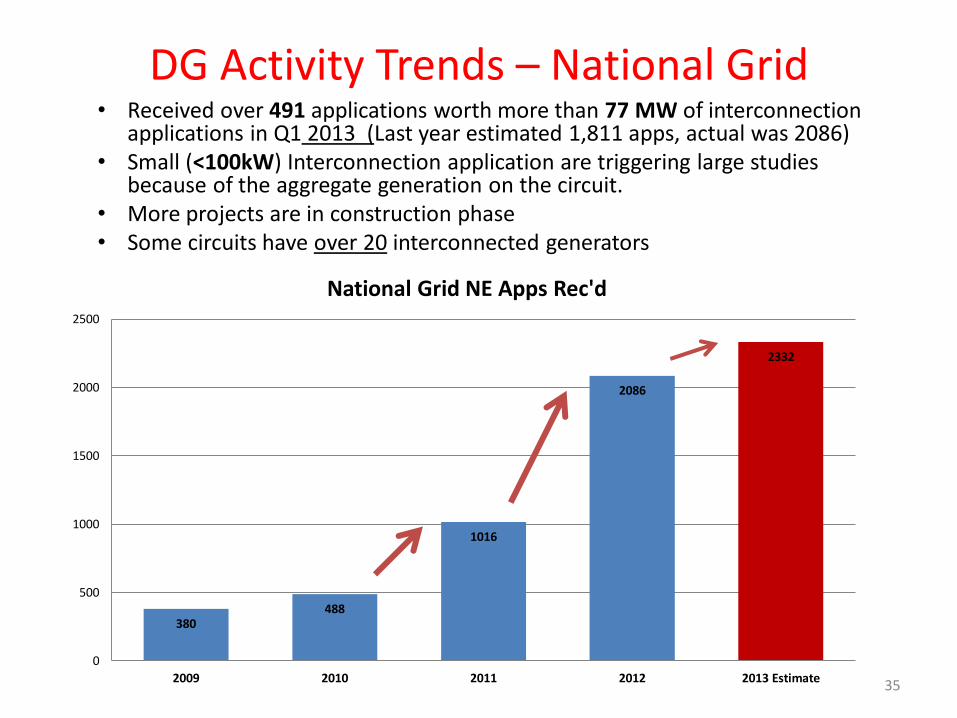
DG Activity Trends – National Grid • Received over 491 applications worth more than 77 MW of interconnection
applications in Q1 2013 (Last year estimated 1,811 apps, actual was 2086) • Small (<100kW) Interconnection application are triggering large studies
because of the aggregate generation on the circuit. • More projects are in construction phase • Some circuits have over 20 interconnected generators
35
380 488
1016
2086
2332
0
500
1000
1500
2000
2500
2009 2010 2011 2012 2013 Estimate
National Grid NE Apps Rec'd
• This presentation will review the interconnection standard (Interconnection Tariff) applicable to generators that will connect (grid tied) to the Distribution System (either to a 69 kV line or lower).
• Generally, generation systems are considered DG if they are going to connect to the distribution system. In this case, the owner must follow the local utility’s interconnection process.
• If you would like to apply to the transmission system (generally larger systems), you need to apply to the New England Independent System Operator (ISO-NE), and are not considered DG.
• If you will be selling your power to a third party, you may have to apply through ISO-NE
• If circuit is already “FERC Jurisdictional” you may need to apply to ISO-NE. http://www.iso-ne.com/genrtion_resrcs/nwgen_inter/index.html
State vs. ISO-NE Process
36
37
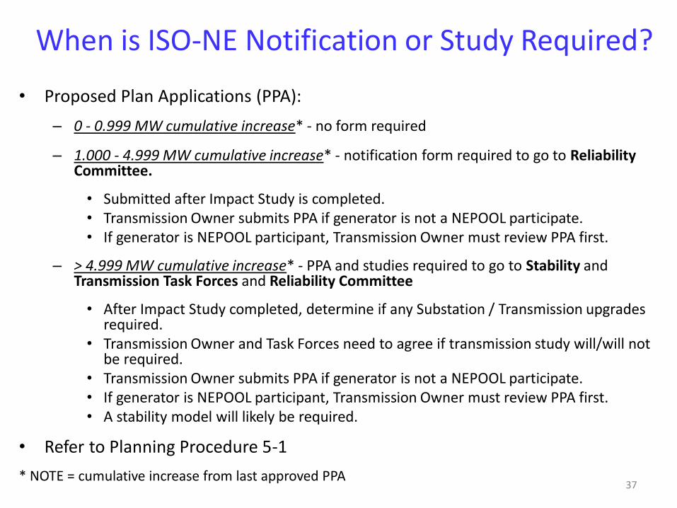
When is ISO-NE Notification or Study Required?
• Proposed Plan Applications (PPA):
– 0 - 0.999 MW cumulative increase* - no form required
– 1.000 - 4.999 MW cumulative increase* - notification form required to go to Reliability Committee.
• Submitted after Impact Study is completed. • Transmission Owner submits PPA if generator is not a NEPOOL participate. • If generator is NEPOOL participant, Transmission Owner must review PPA first.
– > 4.999 MW cumulative increase* - PPA and studies required to go to Stability and Transmission Task Forces and Reliability Committee
• After Impact Study completed, determine if any Substation / Transmission upgrades required.
• Transmission Owner and Task Forces need to agree if transmission study will/will not be required.
• Transmission Owner submits PPA if generator is not a NEPOOL participate. • If generator is NEPOOL participant, Transmission Owner must review PPA first. • A stability model will likely be required.
• Refer to Planning Procedure 5-1
* NOTE = cumulative increase from last approved PPA
38
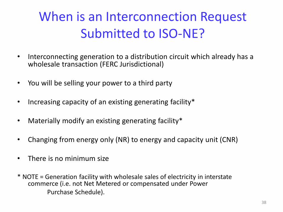
When is an Interconnection Request Submitted to ISO-NE?
• Interconnecting generation to a distribution circuit which already has a wholesale transaction (FERC Jurisdictional)
• You will be selling your power to a third party • Increasing capacity of an existing generating facility* • Materially modify an existing generating facility* • Changing from energy only (NR) to energy and capacity unit (CNR) • There is no minimum size
* NOTE = Generation facility with wholesale sales of electricity in interstate
commerce (i.e. not Net Metered or compensated under Power Purchase Schedule).
39
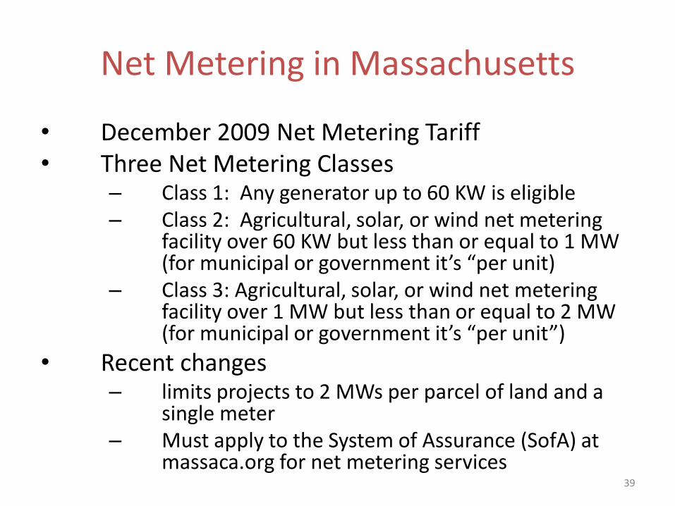
Net Metering in Massachusetts
• December 2009 Net Metering Tariff • Three Net Metering Classes
– Class 1: Any generator up to 60 KW is eligible – Class 2: Agricultural, solar, or wind net metering
facility over 60 KW but less than or equal to 1 MW (for municipal or government it’s “per unit)
– Class 3: Agricultural, solar, or wind net metering facility over 1 MW but less than or equal to 2 MW (for municipal or government it’s “per unit”)
• Recent changes – limits projects to 2 MWs per parcel of land and a
single meter – Must apply to the System of Assurance (SofA) at
massaca.org for net metering services
40
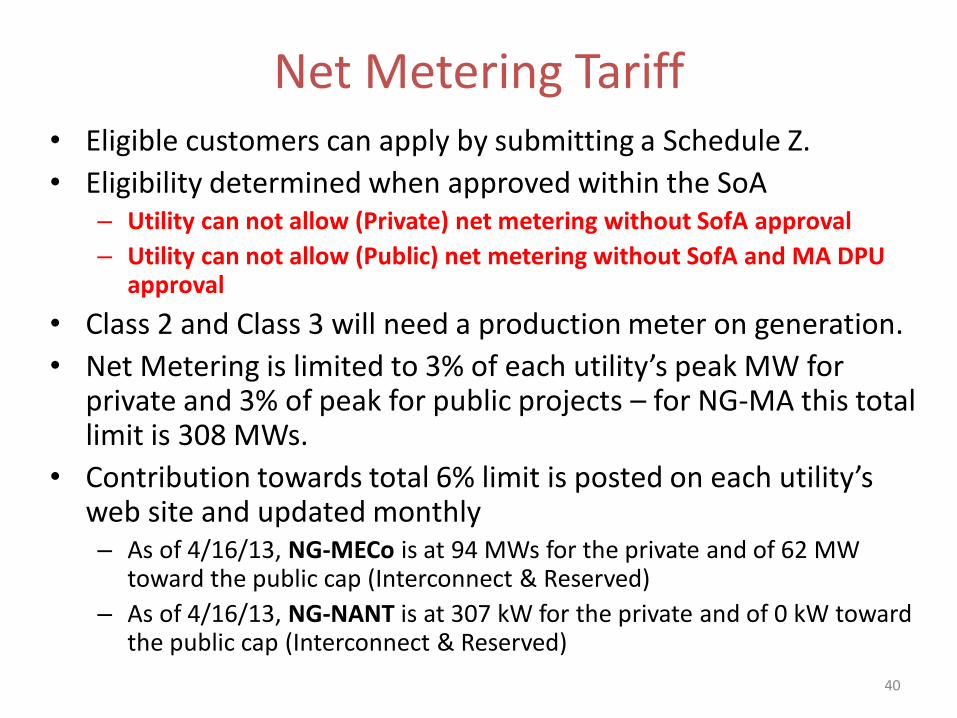
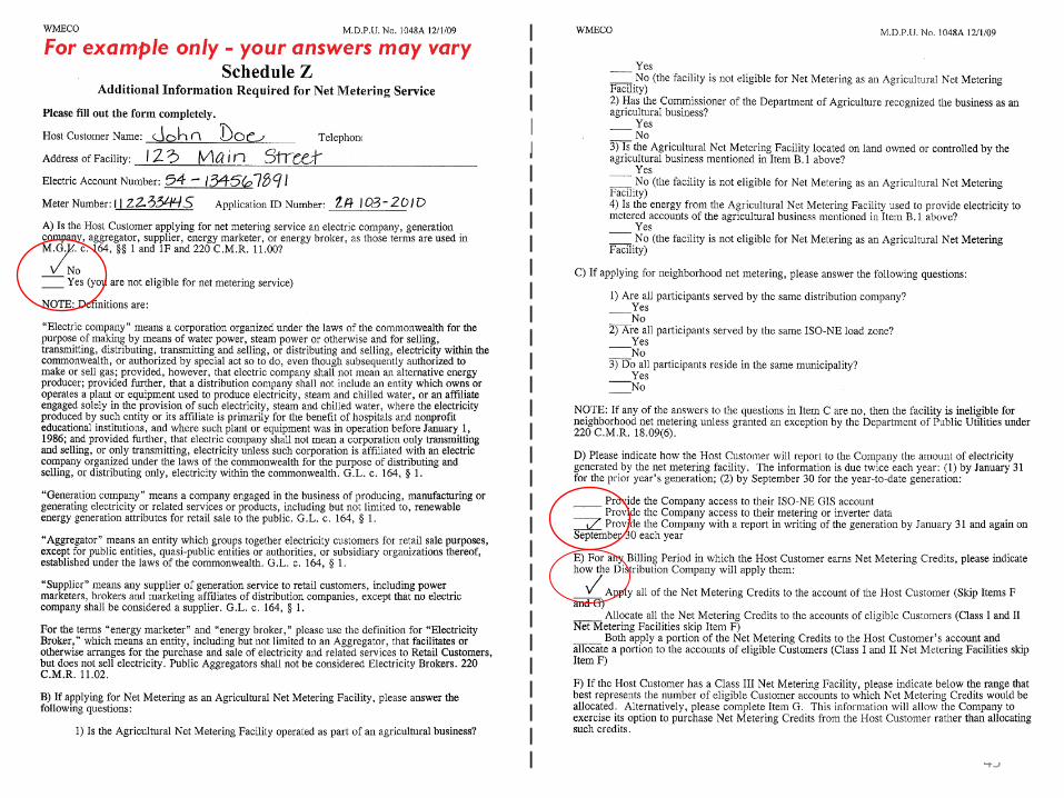
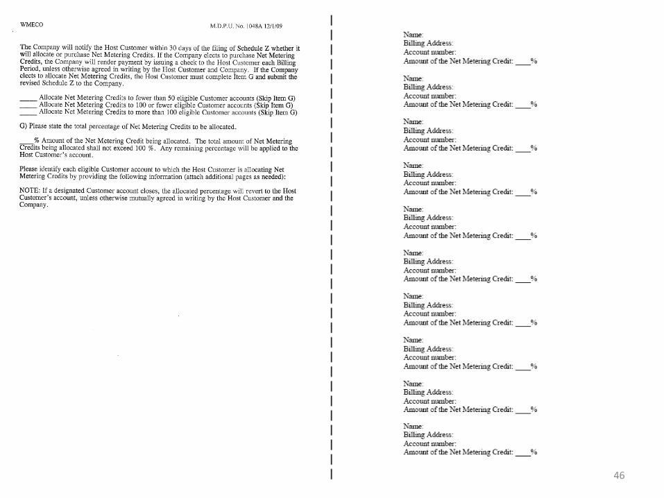
Net Metering Tariff • Eligible customers can apply by submitting a Schedule Z.
• Eligibility determined when approved within the SoA – Utility can not allow (Private) net metering without SofA approval
– Utility can not allow (Public) net metering without SofA and MA DPU approval
• Class 2 and Class 3 will need a production meter on generation.
• Net Metering is limited to 3% of each utility’s peak MW for private and 3% of peak for public projects – for NG-MA this total limit is 308 MWs.
• Contribution towards total 6% limit is posted on each utility’s web site and updated monthly – As of 4/16/13, NG-MECo is at 94 MWs for the private and of 62 MW
toward the public cap (Interconnect & Reserved)
– As of 4/16/13, NG-NANT is at 307 kW for the private and of 0 kW toward the public cap (Interconnect & Reserved)
Net Metering changes
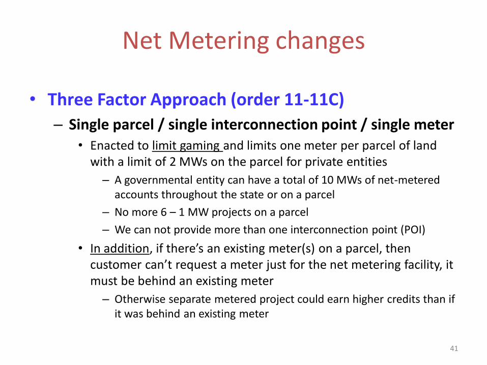
• Three Factor Approach (order 11-11C)
– Single parcel / single interconnection point / single meter • Enacted to limit gaming and limits one meter per parcel of land
with a limit of 2 MWs on the parcel for private entities
– A governmental entity can have a total of 10 MWs of net-metered accounts throughout the state or on a parcel
– No more 6 – 1 MW projects on a parcel
– We can not provide more than one interconnection point (POI)
• In addition, if there’s an existing meter(s) on a parcel, then customer can’t request a meter just for the net metering facility, it must be behind an existing meter
– Otherwise separate metered project could earn higher credits than if it was behind an existing meter
41
Net Metering and Interconnection Order
• Net Metering eligibility – The DPU ruled in the interconnection tariff order (10-75E) that “Early
ISA’s” will NOT meet the executed ISA requirement for entrance into the System of Assurance, and will refer the matter to DPU 11-11 for further investigation.
– Until such time as the DPU reaches a resolution of the issue, Distribution Companies are directed to clearly mark Early ISAs on the title page and on the signature page with the words “Early ISA” for identification purposes.

43
Net Metering Credits
Credit the following charges
Tier min max Type
Default
Service
kWH
Dist-
ribution
kWH
Trans-
mission
kWH
Trans-
ition
kWH
1 0 60 KW
Agriculture
Wind, PV X X X X
2 >60 KW 1 MW
Agriculture
Wind, PV X X X X
3 >1 MW 2 MW
Agriculture
Wind, PV X Gov’t only X X
• Energy use is “netted” over the billing month – If there is net energy use – utility will bill customer for net use – If net energy export – export kWH * the following
• Renewable installations will be credited at near retail rate for excess kWH (minus conservation and renewable energy charges).
• Non-Renewable credited at average monthly clearing price ISO-NE
• Tariff allows credits to be allocated (with limitations) • Customer still responsible for customer charges and demand
charges, even if net export
44
Compensation if not Net Metered • If the customer will never export power – no concern
• If customer will export power – they can sell their exported power to the market through a registered market participant.
– If customer has a Qualifying Facility (QF) certificate from FERC for the generator, they can “sell” to local utility (Power Purchase Schedule).
– Customer can work with any registered market participants to sell power
– Customer must pay for all power they use.
FERC QF page: http://www.ferc.gov/industries/electric/gen-info/qual-fac.asp
45
46

47

48
Net Metering Production Reporting
• Net Metering Tariff requires reporting of generator’s kWH output.
• Class 1 Facilities to provide in writing by January 31 and September 30
• Class 2 and Class 3 Facilities may participate in production tracking system (PTS).
– Mass CEC provided PTS data to the utilities, still working through implementation issues
– Utility will request data from Class 2 and 3 Facilities
49
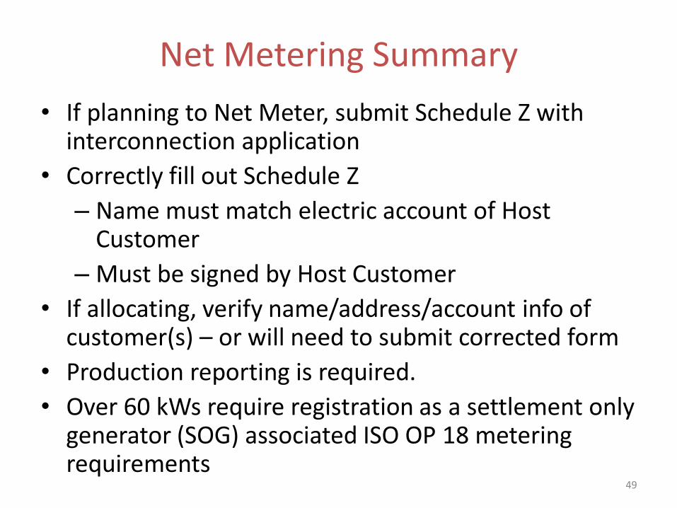
Net Metering Summary
• If planning to Net Meter, submit Schedule Z with interconnection application
• Correctly fill out Schedule Z
– Name must match electric account of Host Customer
– Must be signed by Host Customer
• If allocating, verify name/address/account info of customer(s) – or will need to submit corrected form
• Production reporting is required.
• Over 60 kWs require registration as a settlement only generator (SOG) associated ISO OP 18 metering requirements
Break: 5 Minutes
50
Technical Aspects of Integrating DG with the Utility Distribution EPS
Neil LaBrake, Jr.
Manager, Retail Connections Engineering National Grid
51
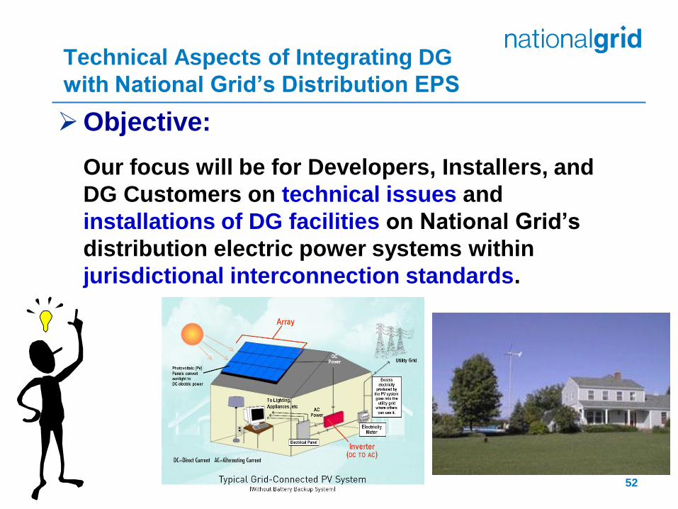
Objective:
Our focus will be for Developers, Installers, and
DG Customers on technical issues and
installations of DG facilities on National Grid’s
distribution electric power systems within
jurisdictional interconnection standards.
Technical Aspects of Integrating DG
with National Grid’s Distribution EPS
52

What are the local rules that apply to DG interconnections?
National Grid ESB 756 Parallel Generation Requirements
Originates from the ESB 750 Series and applicable Company tariffs in each state jurisdiction
ESB 756 main document
Appendices to ESB 756 for Jurisdictional Requirements
Some key factors that influence the revision/update of Electric Service Requirements are:
Government
DPU (Massachusetts), PSC (NY), and PUC (one each for NH & RI)
FERC
Federal, State, and Local Laws
MA Court Rules: Solar PV Installations are Electrical. PHYSICAL INSTALLATION of PV Systems Must Be Done by LICENSED ELECTRICIANS. [July 2012 ruling by Suffolk Superior Court]
Company tariffs
Company policies & practices
National codes
Interconnection Standards: Local Rules – National Grid
www.nationalgridus.com/electricalspecifications
Each utility has their requirements
pursuant to the regulations that
govern them as varying from state-to-
state based on the NESC.
53
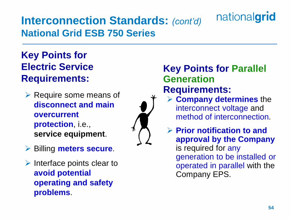
Key Points for
Electric Service
Requirements:
Require some means of
disconnect and main
overcurrent
protection, i.e.,
service equipment.
Billing meters secure.
Interface points clear to
avoid potential
operating and safety
problems.
Interconnection Standards: (cont’d)
National Grid ESB 750 Series
Key Points for Parallel Generation Requirements: Company determines the
interconnect voltage and method of interconnection.
Prior notification to and approval by the Company is required for any generation to be installed or operated in parallel with the Company EPS.
54
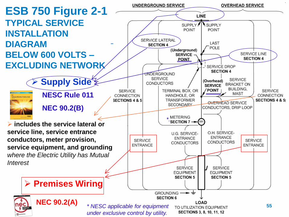
includes the service lateral or
service line, service entrance
conductors, meter provision,
service equipment, and grounding
where the Electric Utility has Mutual
Interest
ESB 750 Figure 2-1 TYPICAL SERVICE
INSTALLATION
DIAGRAM
BELOW 600 VOLTS –
EXCLUDING NETWORK
Premises Wiring
Supply Side
NESC Rule 011
NEC 90.2(B)
NEC 90.2(A) * NESC applicable for equipment
under exclusive control by utility.
*.
55
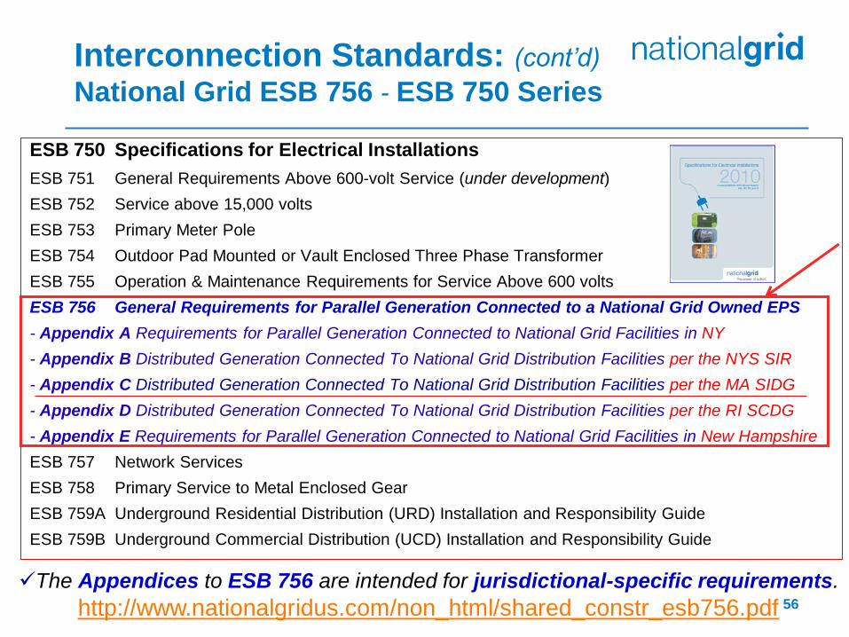
ESB 750 Specifications for Electrical Installations
ESB 751 General Requirements Above 600-volt Service (under development)
ESB 752 Service above 15,000 volts
ESB 753 Primary Meter Pole
ESB 754 Outdoor Pad Mounted or Vault Enclosed Three Phase Transformer
ESB 755 Operation & Maintenance Requirements for Service Above 600 volts
ESB 756 General Requirements for Parallel Generation Connected to a National Grid Owned EPS
- Appendix A Requirements for Parallel Generation Connected to National Grid Facilities in NY
- Appendix B Distributed Generation Connected To National Grid Distribution Facilities per the NYS SIR
- Appendix C Distributed Generation Connected To National Grid Distribution Facilities per the MA SIDG
- Appendix D Distributed Generation Connected To National Grid Distribution Facilities per the RI SCDG
- Appendix E Requirements for Parallel Generation Connected to National Grid Facilities in New Hampshire
ESB 757 Network Services
ESB 758 Primary Service to Metal Enclosed Gear
ESB 759A Underground Residential Distribution (URD) Installation and Responsibility Guide
ESB 759B Underground Commercial Distribution (UCD) Installation and Responsibility Guide
Interconnection Standards: (cont’d)
National Grid ESB 756 - ESB 750 Series
The Appendices to ESB 756 are intended for jurisdictional-specific requirements.
http://www.nationalgridus.com/non_html/shared_constr_esb756.pdf 56
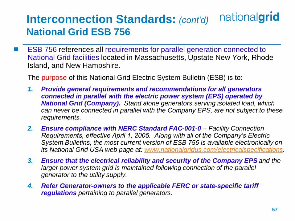
ESB 756 references all requirements for parallel generation connected to National Grid facilities located in Massachusetts, Upstate New York, Rhode Island, and New Hampshire.
The purpose of this National Grid Electric System Bulletin (ESB) is to:
1. Provide general requirements and recommendations for all generators connected in parallel with the electric power system (EPS) operated by National Grid (Company). Stand alone generators serving isolated load, which can never be connected in parallel with the Company EPS, are not subject to these requirements.
2. Ensure compliance with NERC Standard FAC-001-0 – Facility Connection Requirements, effective April 1, 2005. Along with all of the Company’s Electric System Bulletins, the most current version of ESB 756 is available electronically on its National Grid USA web page at: www.nationalgridus.com/electricalspecifications.
3. Ensure that the electrical reliability and security of the Company EPS and the larger power system grid is maintained following connection of the parallel generator to the utility supply.
4. Refer Generator-owners to the applicable FERC or state-specific tariff regulations pertaining to parallel generators.
Interconnection Standards: (cont’d)
National Grid ESB 756
57
Interconnection Standards: (cont’d)
National Grid ESB 756 Appendices
58
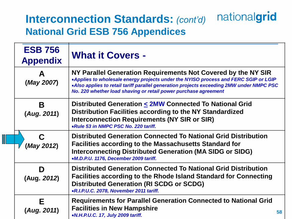
ESB 756
Appendix What it Covers -
A (May 2007)
NY Parallel Generation Requirements Not Covered by the NY SIR Applies to wholesale energy projects under the NYISO process and FERC SGIP or LGIP
Also applies to retail tariff parallel generation projects exceeding 2MW under NMPC PSC
No. 220 whether load shaving or retail power purchase agreement
B (Aug. 2011)
Distributed Generation < 2MW Connected To National Grid
Distribution Facilities according to the NY Standardized
Interconnection Requirements (NY SIR or SIR) Rule 53 in NMPC PSC No. 220 tariff.
C (May 2012)
Distributed Generation Connected To National Grid Distribution
Facilities according to the Massachusetts Standard for
Interconnecting Distributed Generation (MA SIDG or SIDG) M.D.P.U. 1176, December 2009 tariff.
D (Aug. 2012)
Distributed Generation Connected To National Grid Distribution
Facilities according to the Rhode Island Standard for Connecting
Distributed Generation (RI SCDG or SCDG) R.I.P.U.C. 2078, November 2011 tariff.
E (Aug. 2011)
Requirements for Parallel Generation Connected to National Grid
Facilities in New Hampshire N.H.P.U.C. 17, July 2009 tariff.
Interconnection Standards: (cont’d)
National Grid ESB 756 Appendices B - E
59
National Grid strongly believes that promoting the installation of Distributed Generation (DG) facilities, in accordance with state jurisdictional standardized interconnection requirements, is sound public policy.
The state jurisdictional ESB 756 Appendix B, or C, or D, or E supplements ESB 750 and the state regulations and provides general requirements, recommendations, and assistance to customers regarding DG facilities connected in parallel to the Company’s distribution electric power system (Company Distribution EPS).
Will consider DG facilities on network systems to the extent technically feasible.
If a project will be selling their energy to a third party, not National Grid as a Qualifying Facility (QF) or under the net-metering tariff, then the customer will need to apply and work with the NY ISO or ISO-NE for interconnection to the distribution system.
Interconnection Standards: (cont’d)
Massachusetts Technical Standard Review Group (TSRG)
60
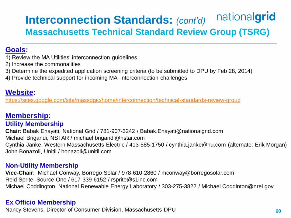
Goals: 1) Review the MA Utilities’ interconnection guidelines
2) Increase the commonalities
3) Determine the expedited application screening criteria (to be submitted to DPU by Feb 28, 2014)
4) Provide technical support for incoming MA interconnection challenges
Website: https://sites.google.com/site/massdgic/home/interconnection/technical-standards-review-group
Membership: Utility Membership Chair: Babak Enayati, National Grid / 781-907-3242 / [email protected]
Michael Brigandi, NSTAR / [email protected]
Cynthia Janke, Western Massachusetts Electric / 413-585-1750 / [email protected] (alternate: Erik Morgan)
John Bonazoli, Unitil / [email protected]
Non-Utility Membership Vice-Chair: Michael Conway, Borrego Solar / 978-610-2860 / [email protected]
Reid Sprite, Source One / 617-339-6152 / [email protected]
Michael Coddington, National Renewable Energy Laboratory / 303-275-3822 / [email protected]
Ex Officio Membership Nancy Stevens, Director of Consumer Division, Massachusetts DPU
Interconnection of
Distributed Generation:
Technical Issues
61
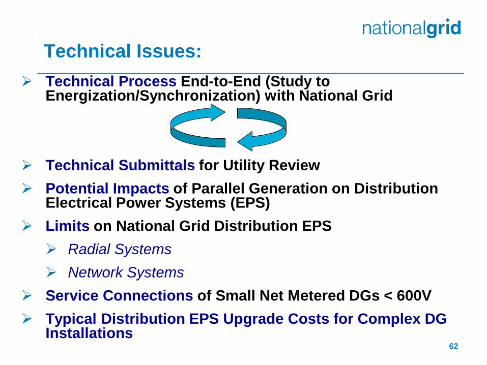
Technical Process End-to-End (Study to Energization/Synchronization) with National Grid
Technical Submittals for Utility Review
Potential Impacts of Parallel Generation on Distribution Electrical Power Systems (EPS)
Limits on National Grid Distribution EPS
Radial Systems
Network Systems
Service Connections of Small Net Metered DGs < 600V
Typical Distribution EPS Upgrade Costs for Complex DG Installations
Technical Issues:
62
For example in MA, see ESB 756 Appendix C:
Section 3.0 for Customer Interface Procedures
Exhibit 2 for Company milestone requirements for projects
not covered by the simplified process (i.e. complex)
Section 4.0 for Interconnection Requirements
Ensure all technical information required in the DG
application under the applicable National Grid tariff is
complete and legible. Additional manufacturer technical
data may be submitted for understanding the specified
electric source’s characteristics to perform the studies.
Technical Issues: Technical Process End-to-End
Refer to the appropriate Appendix of ESB 756 for the
state jurisdiction where DG application is made.
63
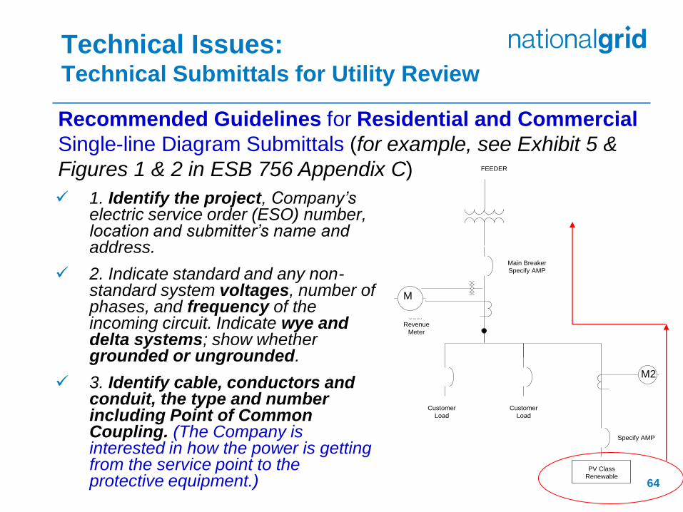
1. Identify the project, Company’s electric service order (ESO) number, location and submitter’s name and address.
2. Indicate standard and any non-standard system voltages, number of phases, and frequency of the incoming circuit. Indicate wye and delta systems; show whether grounded or ungrounded.
3. Identify cable, conductors and conduit, the type and number including Point of Common Coupling. (The Company is interested in how the power is getting from the service point to the protective equipment.)
Technical Issues: Technical Submittals for Utility Review
Recommended Guidelines for Residential and Commercial
Single-line Diagram Submittals (for example, see Exhibit 5 &
Figures 1 & 2 in ESB 756 Appendix C)
M
PV Class
Renewable
M2
Customer
Load
Customer
Load
CL&P FEEDER
CL&P
Revenue
Meter
Main Breaker
Specify AMP
Specify AMP
64
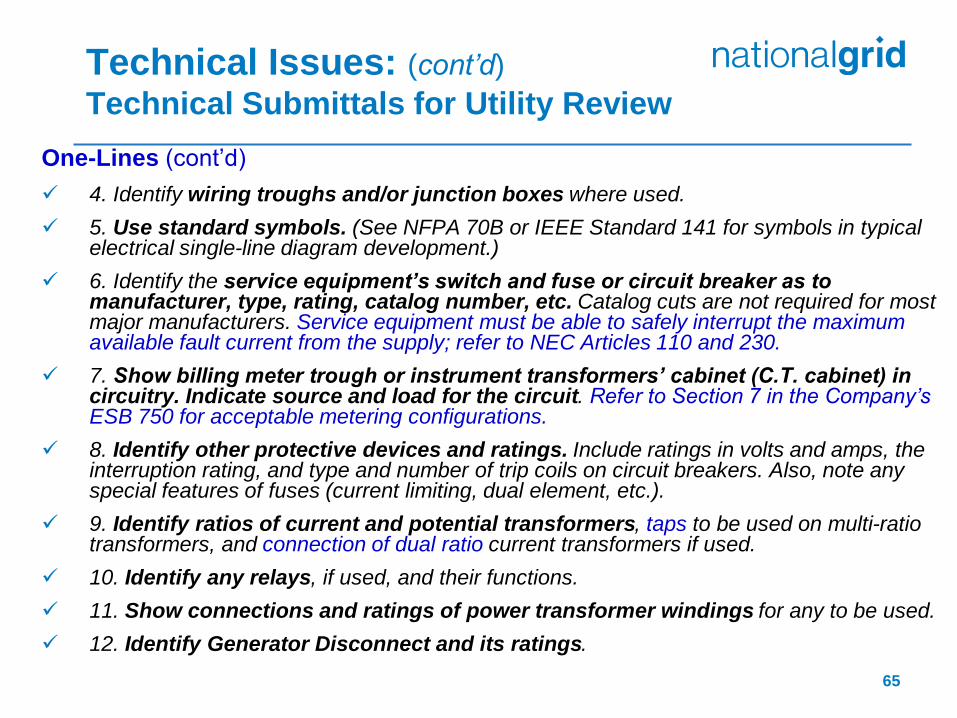
One-Lines (cont’d)
4. Identify wiring troughs and/or junction boxes where used.
5. Use standard symbols. (See NFPA 70B or IEEE Standard 141 for symbols in typical electrical single-line diagram development.)
6. Identify the service equipment’s switch and fuse or circuit breaker as to manufacturer, type, rating, catalog number, etc. Catalog cuts are not required for most major manufacturers. Service equipment must be able to safely interrupt the maximum available fault current from the supply; refer to NEC Articles 110 and 230.
7. Show billing meter trough or instrument transformers’ cabinet (C.T. cabinet) in circuitry. Indicate source and load for the circuit. Refer to Section 7 in the Company’s ESB 750 for acceptable metering configurations.
8. Identify other protective devices and ratings. Include ratings in volts and amps, the interruption rating, and type and number of trip coils on circuit breakers. Also, note any special features of fuses (current limiting, dual element, etc.).
9. Identify ratios of current and potential transformers, taps to be used on multi-ratio transformers, and connection of dual ratio current transformers if used.
10. Identify any relays, if used, and their functions.
11. Show connections and ratings of power transformer windings for any to be used.
12. Identify Generator Disconnect and its ratings.
Technical Issues: (cont’d)
Technical Submittals for Utility Review
65

Recommended Guidelines for Functional Single-line
Diagram Submittals (for example, see Exhibit 6 & Figures 3 & 4
in ESB 756 Appendix C)
Technical Issues: (cont’d)
Technical Submittals for Utility Review
In addition to those items in the previous slides:
13. On functional single-line diagram submittals, industry standard device numbers are necessary. (Refer to the Standard Device Numbers in latest edition of ANSI C 37.2.)
For Protection Schemes:
Three Line (AC Schematic)
Including all AC Current and Voltage circuits
Control Schematic (DC Elementary Diagram)
Including protection functions
Tripping schemes 66
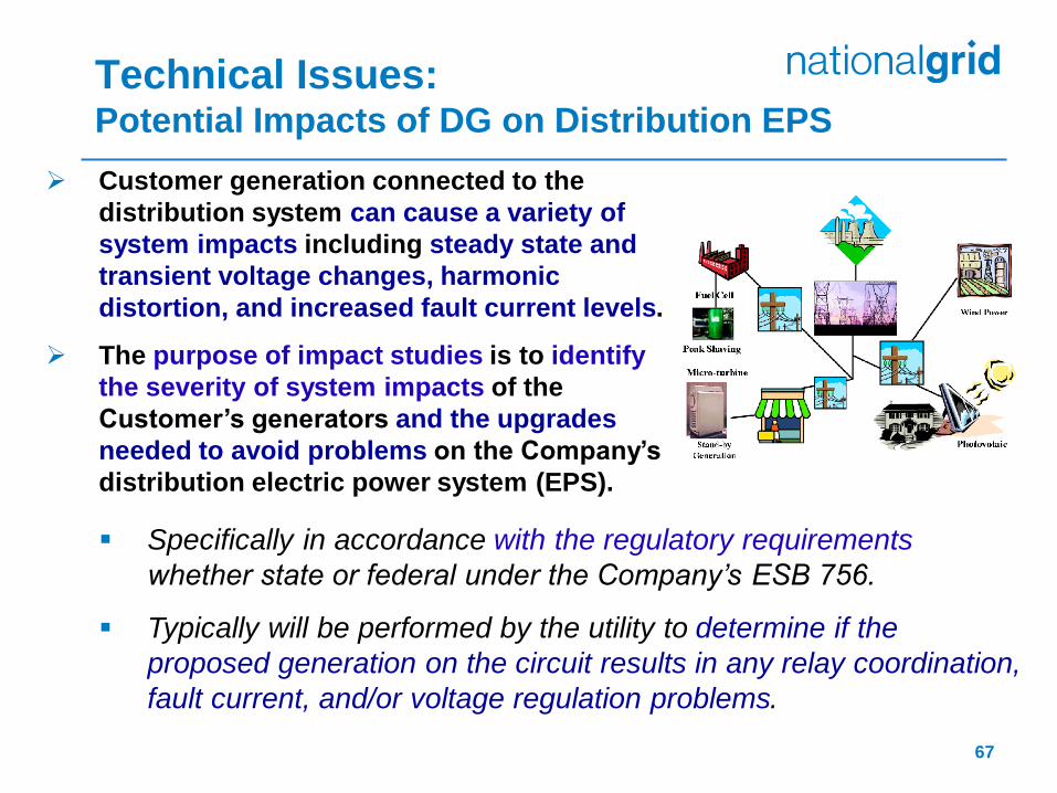
Technical Issues: Potential Impacts of DG on Distribution EPS
Specifically in accordance with the regulatory requirements
whether state or federal under the Company’s ESB 756.
Typically will be performed by the utility to determine if the
proposed generation on the circuit results in any relay coordination,
fault current, and/or voltage regulation problems.
Customer generation connected to the
distribution system can cause a variety of
system impacts including steady state and
transient voltage changes, harmonic
distortion, and increased fault current levels.
The purpose of impact studies is to identify
the severity of system impacts of the
Customer’s generators and the upgrades
needed to avoid problems on the Company’s
distribution electric power system (EPS).
67
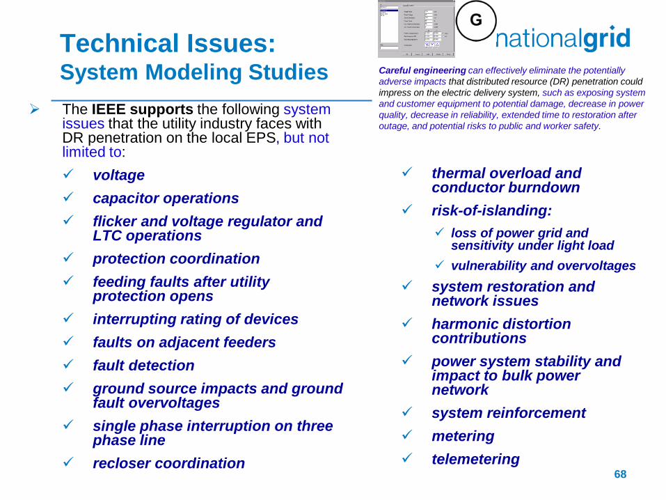
The IEEE supports the following system issues that the utility industry faces with DR penetration on the local EPS, but not limited to:
voltage
capacitor operations
flicker and voltage regulator and LTC operations
protection coordination
feeding faults after utility protection opens
interrupting rating of devices
faults on adjacent feeders
fault detection
ground source impacts and ground fault overvoltages
single phase interruption on three phase line
recloser coordination
Technical Issues: System Modeling Studies
thermal overload and conductor burndown
risk-of-islanding:
loss of power grid and sensitivity under light load
vulnerability and overvoltages
system restoration and network issues
harmonic distortion contributions
power system stability and impact to bulk power network
system reinforcement
metering
telemetering 68
Careful engineering can effectively eliminate the potentially
adverse impacts that distributed resource (DR) penetration could
impress on the electric delivery system, such as exposing system
and customer equipment to potential damage, decrease in power
quality, decrease in reliability, extended time to restoration after
outage, and potential risks to public and worker safety.
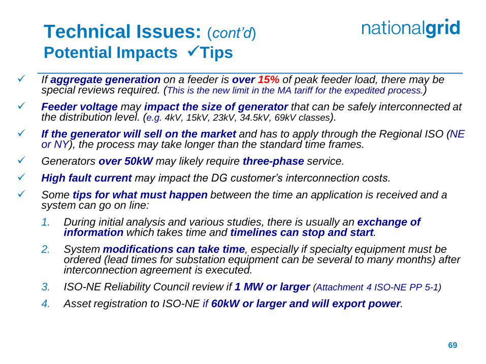
If aggregate generation on a feeder is over 15% of peak feeder load, there may be special reviews required. (This is the new limit in the MA tariff for the expedited process.)
Feeder voltage may impact the size of generator that can be safely interconnected at the distribution level. (e.g. 4kV, 15kV, 23kV, 34.5kV, 69kV classes).
If the generator will sell on the market and has to apply through the Regional ISO (NE or NY), the process may take longer than the standard time frames.
Generators over 50kW may likely require three-phase service.
High fault current may impact the DG customer’s interconnection costs.
Some tips for what must happen between the time an application is received and a system can go on line:
1. During initial analysis and various studies, there is usually an exchange of information which takes time and timelines can stop and start.
2. System modifications can take time, especially if specialty equipment must be ordered (lead times for substation equipment can be several to many months) after interconnection agreement is executed.
3. ISO-NE Reliability Council review if 1 MW or larger (Attachment 4 ISO-NE PP 5-1)
4. Asset registration to ISO-NE if 60kW or larger and will export power.
Technical Issues: (cont’d)
Potential Impacts Tips
69

Generator must be installed behind utility revenue meter
Cannot interconnect in meter socket or trough
Cold sequence metering required
Approved disconnect means must be provided to isolate metering instrument transformers
Metering with remote data access required for all generation 60kW and larger that will export power onto utility EPS
Installation over 500kW will also require a Recloser with remote control and data access to be installed to:
Monitor voltage, current
Act as a utility controlled protective device for onsite utility equipment, i.e. metering for adequate coordination with the EPS
Provide for utility remote disconnect for emergency operations
Technical Issues: (cont’d)
Potential Impacts Metering, Disconnection and Data Acquisition
70

Taps Ahead of Service Equipment for DG Interconnection –
Concerns
Technical Issues: Small Net Metered DG Installations less than 600V
The Company’s position is consistent
with the rules and regulations for
electric service contained in the
Company’s ESB 750-2010 “blue
book” regarding taps and splices
ahead of service equipment and in
meter sockets.
In addition, our rules are consistent with
other utility practices.
Taps and splices in meter sockets
having National Grid meters are
prohibited according to the electric
service requirements of ESB 750.
Doing so causes undue pressure on the
meter socket blocks, increasing the chance
of the blocks breaking, and causing a flash
when the meter is removed. 71
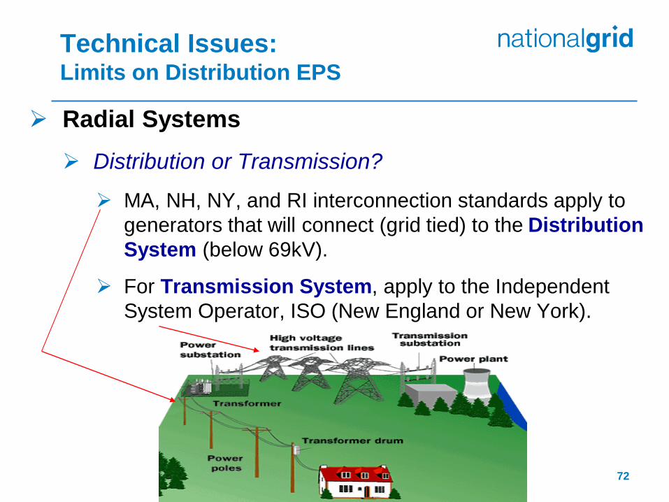
Radial Systems
Distribution or Transmission?
MA, NH, NY, and RI interconnection standards apply to
generators that will connect (grid tied) to the Distribution
System (below 69kV).
For Transmission System, apply to the Independent
System Operator, ISO (New England or New York).
Technical Issues: Limits on Distribution EPS
72

The distribution system was not designed with Distributed Generation in mind. Large generation at this type of system causes challenges (i.e. protection, power regulation…) to distribution and transmission systems.
Based on experience to date, upper limits are established that represent the maximum possible DG capacity under ideal situations and assumes that on the National Grid Distribution EPS there are no additional limitations as indicated by site specific system studies (e.g., available short circuit current contributions, minimum network loading in light loading seasons, voltage regulator interactions, etc.).
When a DG facility (or aggregate DG facility) on a feeder or local EPS of a feeder is above the limits, these warrant further study by National Grid to determine feasibility and remedial action.
Technical Issues: (cont’d)
Limits on Distribution EPS - Radial
73
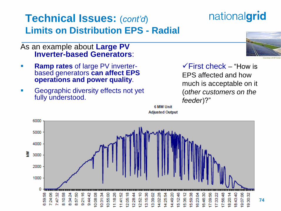
As an example about Large PV Inverter-based Generators:
Ramp rates of large PV inverter-based generators can affect EPS operations and power quality.
Geographic diversity effects not yet fully understood.
Technical Issues: (cont’d)
Limits on Distribution EPS - Radial
First check – “How is
EPS affected and how
much is acceptable on it
(other customers on the
feeder)?”
74
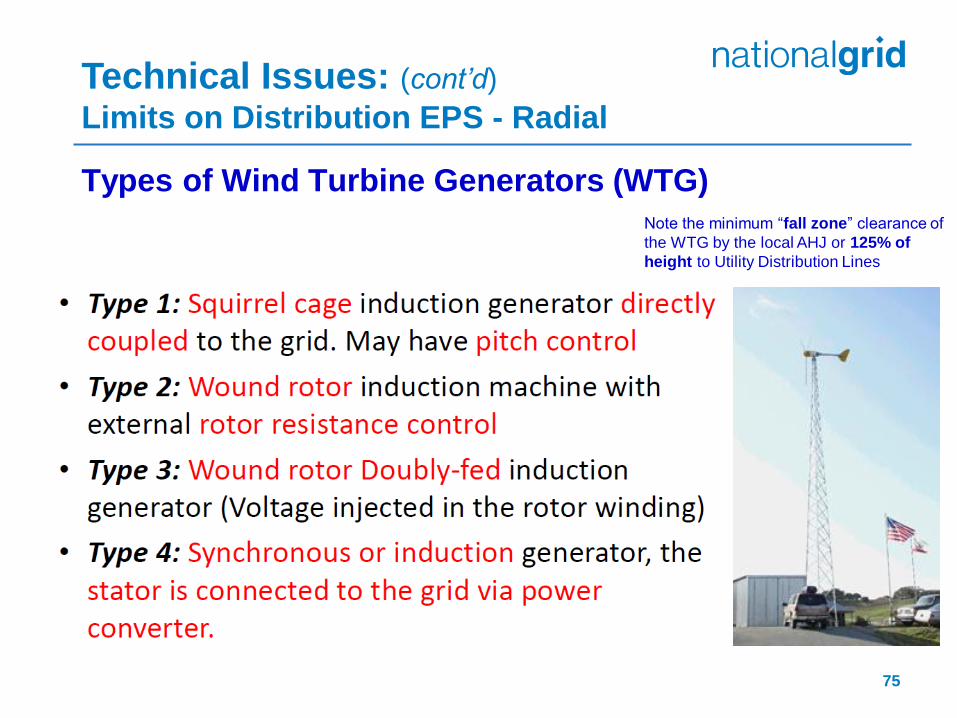
Types of Wind Turbine Generators (WTG)
Technical Issues: (cont’d)
Limits on Distribution EPS - Radial
Note the minimum “fall zone” clearance of
the WTG by the local AHJ or 125% of
height to Utility Distribution Lines
75

Classification Types for Typical DG Installation Areas on Radial Distribution Feeders (for example, see Section 4.0 in ESB 756 Appendix C)
Technical Issues: (cont’d)
Limits on Distribution EPS - Radial
Types of Generators
76
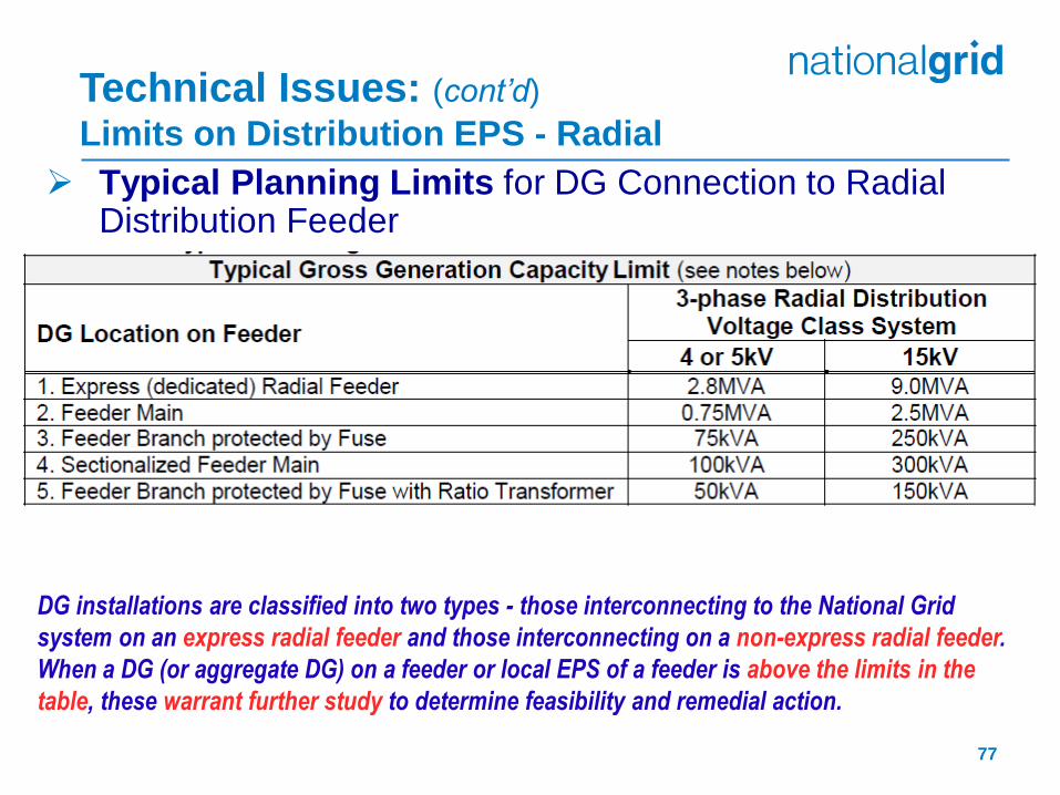
Typical Planning Limits for DG Connection to Radial Distribution Feeder
DG installations are classified into two types - those interconnecting to the National Grid
system on an express radial feeder and those interconnecting on a non-express radial feeder.
When a DG (or aggregate DG) on a feeder or local EPS of a feeder is above the limits in the
table, these warrant further study to determine feasibility and remedial action.
Technical Issues: (cont’d)
Limits on Distribution EPS - Radial
77

Technical Issues: (cont’d)
Limits on Distribution EPS - Radial
78
Typical Planning Limits for DG Connection to Radial Distribution Feeder - cont’d
a. These generation capacities are on a per-generator basis on full nameplate ratings and at unity power factor. It should be noted, however, that the aggregate generation (sum of the total gross generation of all DG systems connected to a particular segment of the Company’s system) is considered for all points along the distribution feeder. The Company will evaluate each application before deciding on the maximum MVA allowed onto the Company’s system at a given point.
b. Limits apply to synchronous and induction rotating generator machines. The DG facility shall maintain power factor at the PCC in accordance with the MA SIDG; at 0.90 Power Factor leading or lagging (for Var or voltage support can also be considered within machine ratings). See ESB 750 regarding disturbances and capacitor installation.
c. Inverter-based systems such as Photovoltaic (PV) Systems are limited in aggregate to 500kVA on 4 or 5kV and in aggregate of large units 500kVA and above up to 3.0MVA on 15kV class systems (this is in addition to small (e.g. residential rooftop) PV until aggregate of these exceeds 500kVA). Operating issues on EPS voltage regulation occur from the effects of cloud transients on large PV systems.
d. Limits for 25kV and 38kV distribution class systems in Massachusetts are determined by the Company on a case-by-case basis.
e. On single-phase radial distribution systems, generators over 50kVA may require three-phase service. These situations will be determined by the Company on a case-by-case basis.
DG facilities typical of synchronous generator and power
factor corrected induction generator types ranging in size
from 750kVA to 2.8MVA at 4 or 5kV class or from
2.5MVA to 9.0MVA at 15kV class, and installed on non-
network systems are considered for connection to
express radial distribution feeders since the light load
condition on the existing feeders may not meet the
acceptable norm to avoid islanding.
Certain other DG types will have different limits to avoid
islanding.
Technical Issues: (cont’d)
Limits on Distribution EPS - Radial
79

So, evaluation checks:
During screenings, check 5-year Plan and if substation can be
expanded for feasibility of express feeder
>3MVA in aggregate of large PV DG units >500kVA on a 15kV
class feeder (depending on VR & Thermal)
3MVA is a soft limit to inform the customer that there might be
some additional system upgrades required. Applications >3MVA
will be studied as well.
Small (e.g. residential rooftop) PV – insignificant additional affect
until aggregate of these exceeds 500kVA
>2.8MVA aggregate of all DG types on substation 4kV or 5kV
bus when supply is 38kV class (depending on VR & Thermal)
>9MVA aggregate of all DG types on substation 15kV bus when
supply is 121kV class (depending on VR & Thermal)
Technical Issues: (cont’d)
Limits on Distribution EPS - Radial
80

Anti-Islanding Protection
The Company’s position is that the interconnection of all parallel generators requires safeguards for synchronization and back-feed situations. A parallel generator is prohibited to energize a de-energized Company circuit.
The Company uses three main “tests”; any determine if anti-islanding protection is required for exceeding minimum load issue or a protection issue or operating concern:
1. “Feeder Light Load versus Generation Test”
2. “Fault Sensitivity and Temporary Overvoltage Test”
3. “Feeder Selectivity Test”
Tips
DG Customer’s protective device coordination study demonstrates generation voltage and/or frequency protection will trip within 2.00 seconds for the loss of the utility source.
Type-tested inverter-based parallel generation operated in regulated current mode, transient overvoltage protection is required upon detection of an island.
When DTT is specified for a parallel generation project, the Company will determine the requirements and responsibilities for equipment, installation, and communications media in the interconnection study.
Technical Issues: Anti-Islanding on Distribution EPS - Radial
81
Technical Issues: Protection Requirements
A parallel generator will contribute to the fault continuously. Hence, overcurrent (OC) protection is required.
Over/Under (O/U) voltage and frequency protection can be used based on the application (Load, Generation, etc.)
Some typical relays used to protect the DGs
51: Time Over Current (Mostly for Synchronous Generators)
51C: Voltage Controlled Time Over Current (Current pickup is constant and is activated when the voltage drops below a certain limit)
27: Under Voltage (For all DGs)
59: Over Voltage (If the utility side of the step up transformer is Delta)
81: Frequency – O/U (All DGs)
82
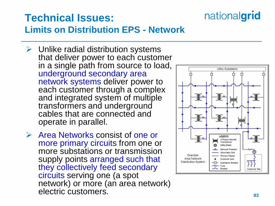
Unlike radial distribution systems that deliver power to each customer in a single path from source to load, underground secondary area network systems deliver power to each customer through a complex and integrated system of multiple transformers and underground cables that are connected and operate in parallel.
Area Networks consist of one or more primary circuits from one or more substations or transmission supply points arranged such that they collectively feed secondary circuits serving one (a spot network) or more (an area network) electric customers.
Technical Issues: Limits on Distribution EPS - Network
83
Technical Issues: (cont’d)
Limits on Distribution EPS - Network
84
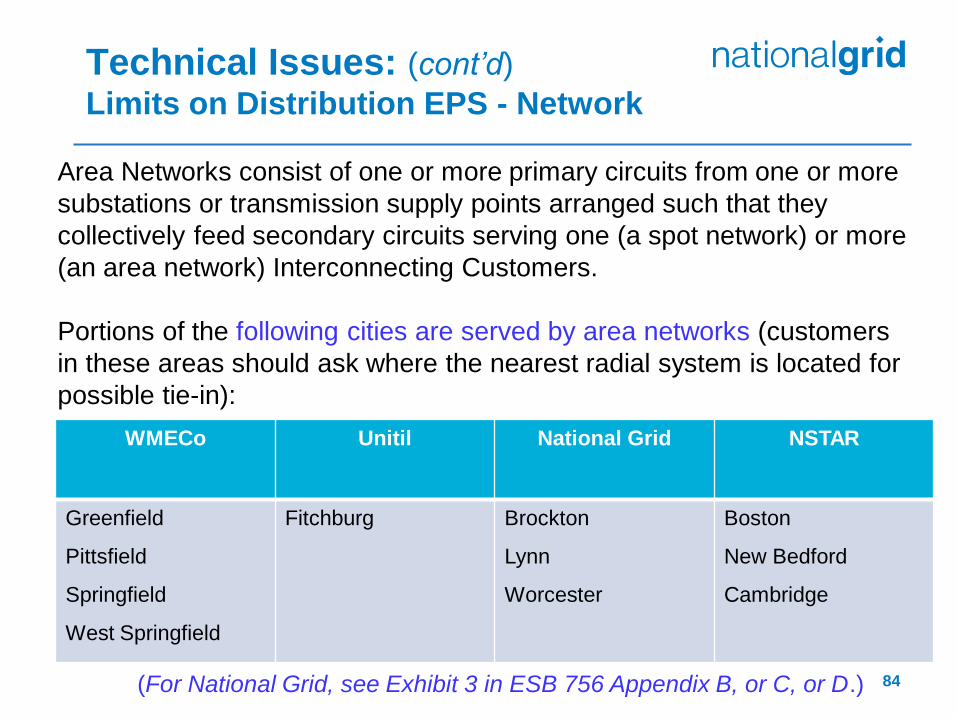
Area Networks consist of one or more primary circuits from one or more
substations or transmission supply points arranged such that they
collectively feed secondary circuits serving one (a spot network) or more
(an area network) Interconnecting Customers.
Portions of the following cities are served by area networks (customers
in these areas should ask where the nearest radial system is located for
possible tie-in):
WMECo Unitil National Grid NSTAR
Greenfield
Pittsfield
Springfield
West Springfield
Fitchburg Brockton
Lynn
Worcester
Boston
New Bedford
Cambridge
(For National Grid, see Exhibit 3 in ESB 756 Appendix B, or C, or D.)

The connection of
customer DG facilities on
networks is an emerging
topic, which
(i) poses some issues
for the Company to
maintain adequate
voltage and worker
safety and
(ii) has the potential to
cause the power flow on
network feeders to shift
(i.e., reverse) causing
network protectors
within the network grid
to trip open.
Technical Issues: (cont’d)
Limits on Distribution EPS - Network
To ensure network safety and reliability additional information will be required for the Company’s engineering analysis such as:
Electric demand profile showing minimum load during peak generation time,
Expected generation profile shown for a 24-hour period and typical 7-day duration, and
Customer’s complete electric service single-line diagram up to the service point supplied by the Company’s secondary network EPS. 85
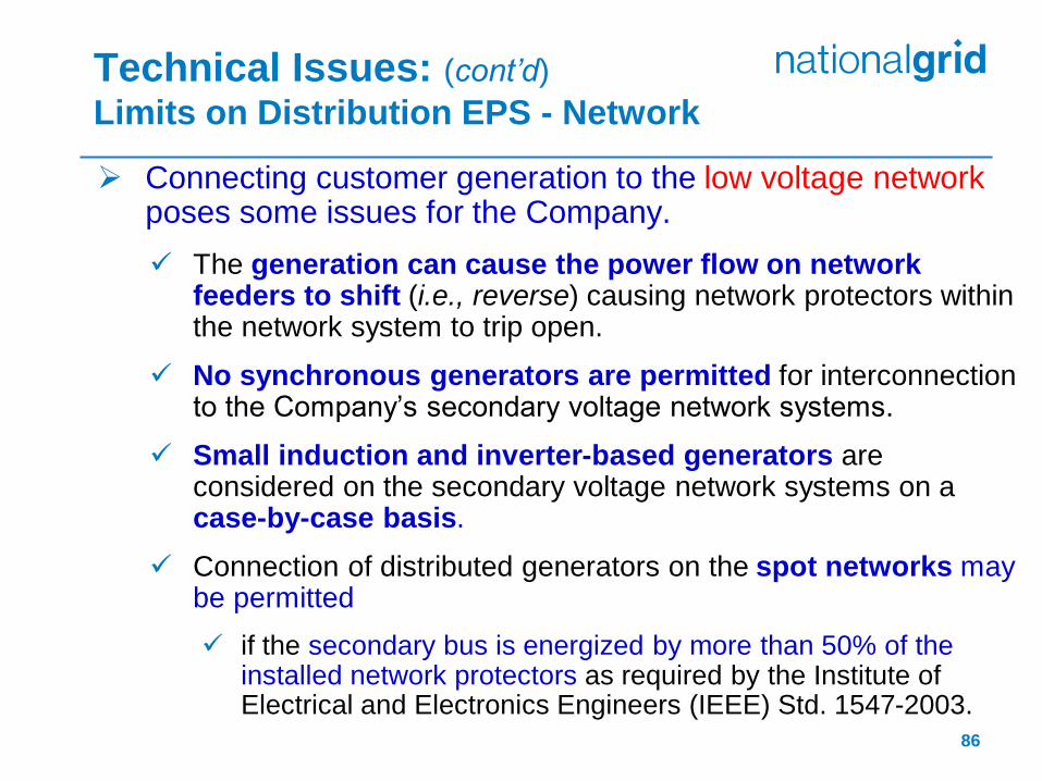
Connecting customer generation to the low voltage network poses some issues for the Company.
The generation can cause the power flow on network feeders to shift (i.e., reverse) causing network protectors within the network system to trip open.
No synchronous generators are permitted for interconnection to the Company’s secondary voltage network systems.
Small induction and inverter-based generators are considered on the secondary voltage network systems on a case-by-case basis.
Connection of distributed generators on the spot networks may be permitted
if the secondary bus is energized by more than 50% of the installed network protectors as required by the Institute of Electrical and Electronics Engineers (IEEE) Std. 1547-2003.
Technical Issues: (cont’d)
Limits on Distribution EPS - Network
86
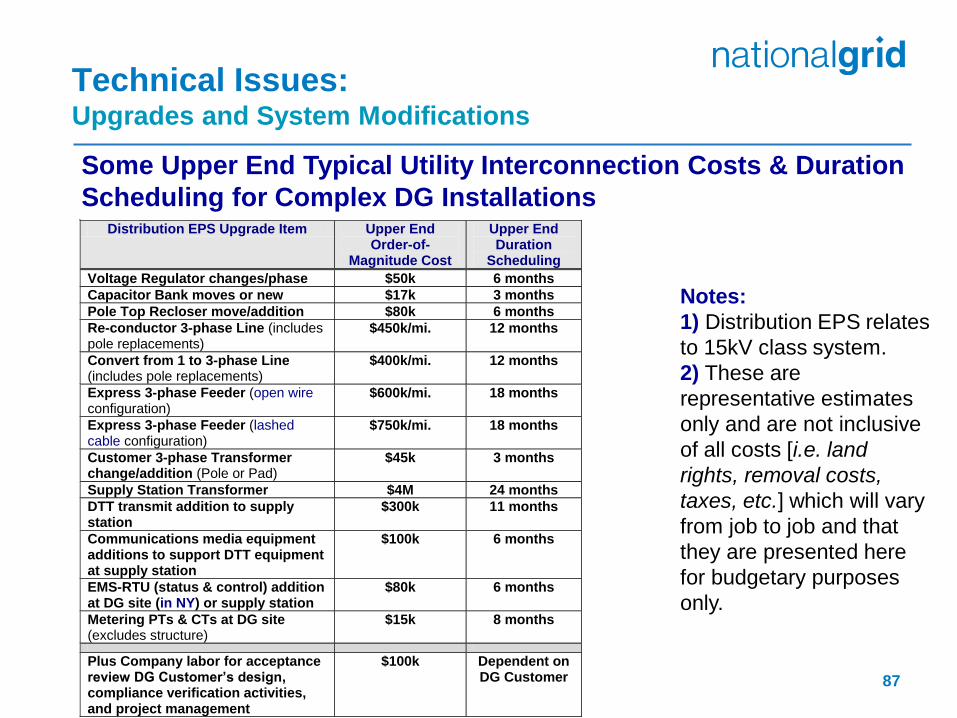
Technical Issues: Upgrades and System Modifications Some Upper End Typical Utility Interconnection Costs & Duration
Scheduling for Complex DG Installations
Notes:
1) Distribution EPS relates
to 15kV class system.
2) These are
representative estimates
only and are not inclusive
of all costs [i.e. land
rights, removal costs,
taxes, etc.] which will vary
from job to job and that
they are presented here
for budgetary purposes
only.
Distribution EPS Upgrade Item Upper End Order-of-
Magnitude Cost
Upper End Duration
Scheduling
Voltage Regulator changes/phase $50k 6 months
Capacitor Bank moves or new $17k 3 months
Pole Top Recloser move/addition $80k 6 months
Re-conductor 3-phase Line (includes pole replacements)
$450k/mi. 12 months
Convert from 1 to 3-phase Line (includes pole replacements)
$400k/mi. 12 months
Express 3-phase Feeder (open wire configuration)
$600k/mi. 18 months
Express 3-phase Feeder (lashed cable configuration)
$750k/mi. 18 months
Customer 3-phase Transformer change/addition (Pole or Pad)
$45k 3 months
Supply Station Transformer $4M 24 months
DTT transmit addition to supply station
$300k 11 months
Communications media equipment additions to support DTT equipment at supply station
$100k 6 months
EMS-RTU (status & control) addition at DG site (in NY) or supply station
$80k 6 months
Metering PTs & CTs at DG site (excludes structure)
$15k 8 months
Plus Company labor for acceptance review DG Customer’s design, compliance verification activities, and project management
$100k Dependent on DG Customer
87
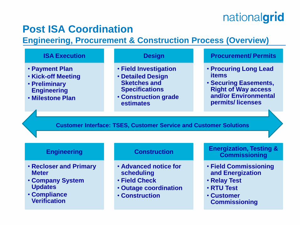
Post ISA Coordination Engineering, Procurement & Construction Process (Overview)
ISA Execution
• Payment Plan
• Kick-off Meeting
• Preliminary Engineering
• Milestone Plan
Design
• Field Investigation
• Detailed Design Sketches and Specifications
• Construction grade estimates
Procurement/ Permits
• Procuring Long Lead items
• Securing Easements, Right of Way access and/or Environmental permits/ licenses
Engineering
• Recloser and Primary Meter
• Company System Updates
• Compliance Verification
Construction
• Advanced notice for scheduling
• Field Check
• Outage coordination
• Construction
Energization, Testing & Commissioning
• Field Commissioning and Energization
• Relay Test
• RTU Test
• Customer Commissioning
Customer Interface: TSES, Customer Service and Customer Solutions
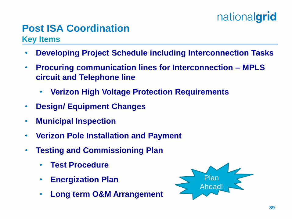
Post ISA Coordination Key Items
• Developing Project Schedule including Interconnection Tasks
• Procuring communication lines for Interconnection – MPLS
circuit and Telephone line
• Verizon High Voltage Protection Requirements
• Design/ Equipment Changes
• Municipal Inspection
• Verizon Pole Installation and Payment
• Testing and Commissioning Plan
• Test Procedure
• Energization Plan
• Long term O&M Arrangement
89
Plan
Ahead!

Post ISA Coordination (cont’d) Witness Testing: Relay Test
90
Timing Task(s) Relay Test 1 month prior to schedule a Relay Test: IC submits proposed settings along with witness
test procedure and Energization Plan (EP). Company to approve settings, EP and test
procedure. On approval from The company: IC to perform their own testing using their own
energy source. Company to confirm successful Field Audit IC submits test results on testing company’s
letterhead. The company to confirm the settings
and error 7 day notice to schedule Relay Test: Company to witness the relay test (Day of Witness
Test) Company to approve test results (Day of Witness
Test) Upon the company’s Energization till PCC: IC to energize as per EP upon submission of formal
test results
IC shall arrange their own source of power to perform calibration tests or tests prior to
the Company Witness Test.

Post ISA Coordination (cont’d) Witness Testing: EMS-RTU Test
91
Timing Task(s)
RTU Test
1 month prior to schedule RTU Test: Customer to submit Functional diagram and
points list
Company to review the information with other
stakeholders
Assign IP address
EMS database update
On approval from the company: Readiness of MPLS circuit for communication
test
Company to confirm EMS-RTU database update
for points
10 day notice to schedule RTU Test: Communication test
Company to witness RTU Test
Company to confirm successful completion of
RTU Test
Upon the company’s Energization till PCC: IC to energize as per EP (Day of RTU Test, if
possible)
Verizon will be performing High Voltage Protection study and there might be
additional cost to install additional equipment for customers.
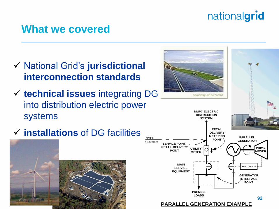
National Grid’s jurisdictional
interconnection standards
technical issues integrating DG
into distribution electric power
systems
installations of DG facilities
NMPC
Customer
PRIME
MOVER
SERVICE POINT/
RETAIL DELIVERY
POINT
Gen. Control
PREMISE
LOADS
MAIN
SERVICE
EQUIPMENT
PARALLEL
GENERATOR
NMPC ELECTRIC
DISTRIBUTION
SYSTEM
UTILITY
METER
PARALLEL GENERATION EXAMPLE
RETAIL
DELIVERY
METERING
POINT
GENERATOR
INTERFACE
POINT
92
What we covered
Questions and Answers
Why do we need an AC Disconnect?
See Section 7.0 of MA Interconnection Tariff.
What could be done to move my project along faster?
Hire an expert to provide us the complete information.
Is there feeder capacity information?
Utility is able to provide preapplication report information.
Beyond that an impact study is required.
93
94
Questions?