IntelliChlor Electronic Chlorine Generator - pentair.com · iv IntelliChlor Electronic Chlorine...
40
IMPORTANT SAFETY INSTRUCTIONS READ AND FOLLOW ALL INSTRUCTIONS SAVE THESE INSTRUCTIONS Installation and User’s Guide Electronic Chlorine Generator (Model CIC60P, CIC60S) Patents pending Certified to NSF/ANSI 50 ® IntelliChlor
Transcript of IntelliChlor Electronic Chlorine Generator - pentair.com · iv IntelliChlor Electronic Chlorine...

IMPORTANT SAFETY INSTRUCTIONSREAD AND FOLLOW ALL INSTRUCTIONS
SAVE THESE INSTRUCTIONS
Installation and User’s Guide
Electronic Chlorine Generator(Model CIC60P, CIC60S)
Patents pending
Certified to NSF/ANSI 50
®IntelliChlor
© 2012 Pentair Water Pool and Spa, Inc. All rights reserved
This document is subject to change without notice
1620 Hawkins Ave., Sanford, NC 27330 • (919) 566-800010951 West Los Angeles Ave., Moorpark, CA 93021 • (805) 553-5000
IntelliChlor®, IntelliTouch®, EasyTouch® and Pentair Water Commercial Pool and Spa™ are trademarks or registeredtrademarks of Pentair Water Pool and Spa, Inc. and/or its affili-ated companies in the United States and/or othercountries. Unless noted, names and brands of others that may be used in this document are not used to indicatean affiliation or endorsement between the proprietors of these names and brands and Pentair Water Pool and Spa,Inc. Those names and brands may be the trademarks or registered trademarks of those parties or others.
P/N 521011 Rev C - 04/9/12
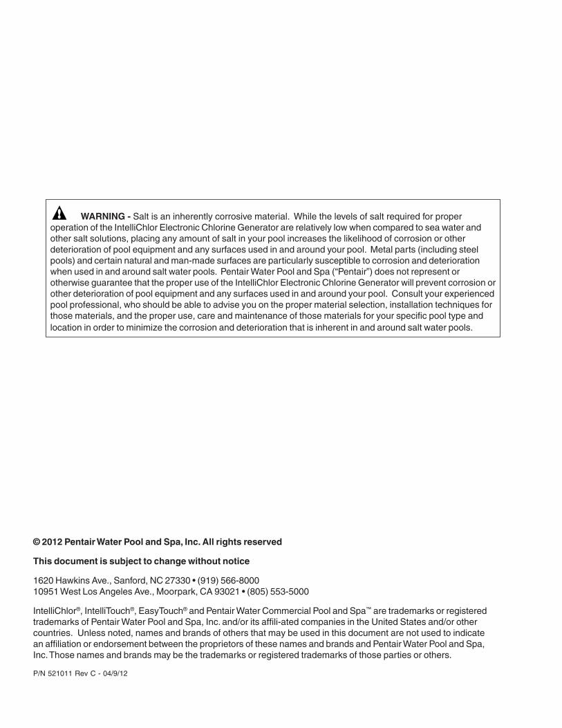
WARNING - Salt is an inherently corrosive material. While the levels of salt required for properoperation of the IntelliChlor Electronic Chlorine Generator are relatively low when compared to sea water andother salt solutions, placing any amount of salt in your pool increases the likelihood of corrosion or otherdeterioration of pool equipment and any surfaces used in and around your pool. Metal parts (including steelpools) and certain natural and man-made surfaces are particularly susceptible to corrosion and deteriorationwhen used in and around salt water pools. Pentair Water Pool and Spa (“Pentair”) does not represent orotherwise guarantee that the proper use of the IntelliChlor Electronic Chlorine Generator will prevent corrosion orother deterioration of pool equipment and any surfaces used in and around your pool. Consult your experiencedpool professional, who should be able to advise you on the proper material selection, installation techniques forthose materials, and the proper use, care and maintenance of those materials for your specific pool type andlocation in order to minimize the corrosion and deterioration that is inherent in and around salt water pools.
i
IntelliChlor Electronic Chlorine Generator Installation and User’s Guide
Contents
Important Safety Precautions ........................................................................................................... iii - ivIntelliChlor and Controller System Part Numbers ......................................................................................... vTechnical Support ........................................................................................................................................ vIntelliChlor® Electronic Chlorine Generator Overview................................................................................... 1 Features .................................................................................................................................................. 1IntelliChlor Commercial System Components .............................................................................................. 2Acu-Trol panel with ORP sensor (sold separately) ........................................................................................ 2PC100 Commercial Power Center - No ORP ................................................................................................ 2CPC100 Commercial Power Center with ORP .............................................................................................. 2IntelliChlor Electronic Chlorine Generator Control Panel and Cell Description ............................................... 3IntelliChlor Power Center .............................................................................................................................. 4System Schematic Diagram ........................................................................................................................ 5Install Chlorine/Bromine Feeders after the IntelliChlor Cell ........................................................................... 5IntelliChlor Plumbing Diagram (For single CIC60 cell system) ...................................................................... 6Loop Plumbing Diagram (For single CIC60 cell system)............................................................................... 6
Section 1: IntelliChlor Control Panel .........................................................................................7Salt Level Status LEDs ............................................................................................................................... 7Status LEDs ................................................................................................................................................ 7Sanitizer Output LED Indicators .................................................................................................................. 8Self-Cleaning ............................................................................................................................................... 8More and Less Output Buttons .................................................................................................................... 8Boost ON/OFF ............................................................................................................................................ 8Self-Cleaning ............................................................................................................................................... 8
Section 2: Pool Water and Chemistry, Conditions and Precautions .......................................9Pool Water Chemistry, Conditions and Precautions ...................................................................................... 9Optimum Pool Water Conditions for Salt Water Pools (using the IntelliChlor Electronic Chlorine Generator) 10Covered Pools and Vinyl Liner Pool and Lowering Chlorine Output Levels .................................................. 10Chlorine Testing ......................................................................................................................................... 11What Type of Salt to Use ........................................................................................................................... 11How Much Salt to Use ............................................................................................................................... 11Calculating the Saturation Index ................................................................................................................ 12 TDS Factor ............................................................................................................................................ 12 Langelier Saturation Index Factor .......................................................................................................... 12How to Add Salt to the Pool ....................................................................................................................... 13 Table 1. Approximate Pounds (Kg) of salt needed to obtain 3,400 ppm in pool ...................................... 13 Table 2. Approximate amount of stabilizer (cyanuric acid) to obtain 40 ppm in pool .............................. 14 Table 3. Approximate amount of cyanuric acid to obtain 75 ppm in pool ................................................ 14Pool Water Preparation ............................................................................................................................... 15 Determining Pool Size (Gallons of Water in Your Pool) ........................................................................... 15 Determining Pool Size (liters of water in your pool) ................................................................................ 15
Section 3: Operating IntelliChlor .............................................................................................17Initial Start up Period ................................................................................................................................. 17 Operation .............................................................................................................................................. 17 Use of an external Pool Pump Timer is not required .............................................................................. 17 If you use a Pool Pump Timer ............................................................................................................... 17Startup Procedure (Super Chlorination) ...................................................................................................... 18Sanitizer Output Settings and Adjustments ............................................................................................... 18Operating in Winter .................................................................................................................................... 18 General Recommendations ................................................................................................................... 19 General Cautions .................................................................................................................................... 19
ii
IntelliChlor Electronic Chlorine Generator Installation and User’s Guide
Section 4: User Maintenance.................................................................................................... 21Daily service .............................................................................................................................................. 21Weekly service .......................................................................................................................................... 21Monthly Service......................................................................................................................................... 21IECG Usage Hours Meter .......................................................................................................................... 22Cleaning the IECG Cell Blades .................................................................................................................. 22Winterizing ................................................................................................................................................. 23
Section 5: Installation ...............................................................................................................25Kit Contents .............................................................................................................................................. 25Required Tools ........................................................................................................................................... 25IntelliChlor “Dummy” Cell ........................................................................................................................... 26Installing the IntelliChlor Cell Assembly ..................................................................................................... 26 Connecting the Cell Power Cable to the Power Center ........................................................................... 27
Section 6: Troubleshooting ......................................................................................................29
Table 1: Troubleshooting ............................................................................................................................ 29
System Specifications - 115 VAC and 240 VAC Wiring .............................................................................. 31
Warranty ......................................................................................................................................33
Technical SupportSanford, North Carolina (8 A.M. to 5 P.M. Eastern Time)Moorpark, California (8 A.M. to 5 P.M. Pacific Time)Phone: (800) 831-7133Fax: (800) 284-4151visit www.pentairpool.com and www.staritepool.com
Contents (Continued)
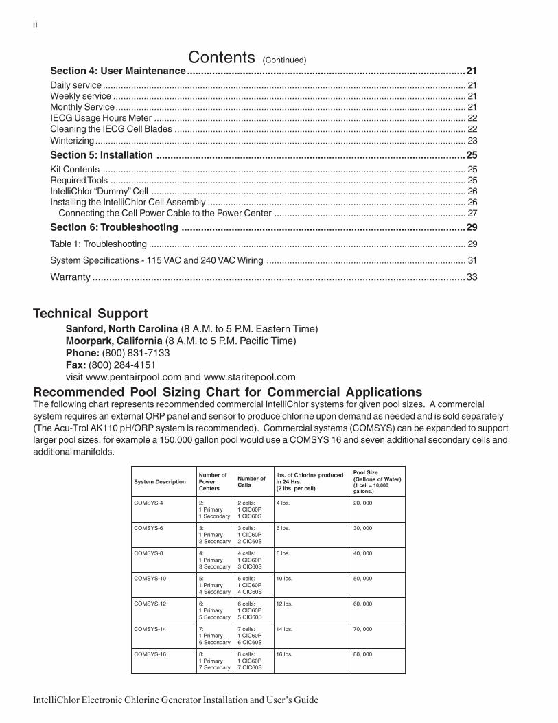
The following chart represents recommended commercial IntelliChlor systems for given pool sizes. A commercialsystem requires an external ORP panel and sensor to produce chlorine upon demand as needed and is sold separately(The Acu-Trol AK110 pH/ORP system is recommended). Commercial systems (COMSYS) can be expanded to supportlarger pool sizes, for example a 150,000 gallon pool would use a COMSYS 16 and seven additional secondary cells andadditional manifolds.
Recommended Pool Sizing Chart for Commercial Applications
noitpircseDmetsySforebmuN
rewoPsretneC
forebmuNslleC
decudorpenirolhCfo.sbl.srH42ni
)llecrep.sbl2(
eziSlooP)retaWfosnollaG(
000,01=llec1().snollag
4-SYSMOC :2yramirP1
yradnoceS1
:sllec2P06CIC1S06CIC1
.sbl4 000,02
6-SYSMOC :3yramirP1
yradnoceS2
:sllec3P06CIC1S06CIC2
.sbl6 000,03
8-SYSMOC :4yramirP1
yradnoceS3
:sllec4P06CIC1S06CIC3
.sbl8 000,04
01-SYSMOC :5yramirP1
yradnoceS4
:sllec5P06CIC1S06CIC4
.sbl01 000,05
21-SYSMOC :6yramirP1
yradnoceS5
:sllec6P06CIC1S06CIC5
.sbl21 000,06
41-SYSMOC :7yramirP1
yradnoceS6
:sllec7P06CIC1S06CIC6
.sbl41 000,07
61-SYSMOC :8yramirP1
yradnoceS7
:sllec8P06CIC1S06CIC7
.sbl61 000,08
iii
IntelliChlor Electronic Chlorine Generator Installation and User’s Guide
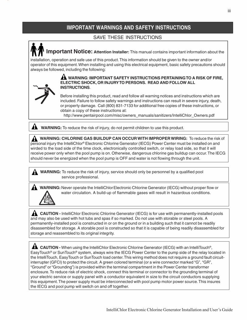
Important Notice: Attention Installer: This manual contains important information about the
installation, operation and safe use of this product. This information should be given to the owner and/oroperator of this equipment. When installing and using this electrical equipment, basic safety precautions shouldalways be followed, including the following:
WARNING: IMPORTANT SAFETY INSTRUCTIONS PERTAINING TO A RISK OF FIRE,ELECTRIC SHOCK, OR INJURY TO PERSONS. READ AND FOLLOW ALLINSTRUCTIONS.
Before installing this product, read and follow all warning notices and instructions which areincluded. Failure to follow safety warnings and instructions can result in severe injury, death,or property damage. Call (800) 831-7133 for additional free copies of these instructions, orobtain a copy of these instructions at:
http://www.pentairpool.com/misc/owners_manuals/sanitizers/IntelliChlor_Owners.pdf
WARNING: To reduce the risk of injury, do not permit children to use this product.
WARNING: CHLORINE GAS BUILDUP CAN OCCUR WITH IMPROPER WIRING: To reduce the risk ofpersonal injury the IntelliChlor® Electronic Chlorine Generator (IECG) Power Center must be installed on andwirded to the load side of the time clock, electronically controlled switch, or relay load side, so that it willreceive power only when the pool pump is on. Otherwise, dangerous chlorine gas buildup can occur. The IECGshould never be energized when the pool pump is OFF and water is not flowing through the unit.
WARNING: To reduce the risk of injury, service should only be personnel by a qualified pool service professional.
WARNING: Never operate the IntelliChlor Electronic Chlorine Generator (IECG) without proper flow or water circulation. A build-up of flammable gases will result in hazardous conditions.
CAUTION - IntelliChlor Electronic Chlorine Generator (IECG) is for use with permanently-installed poolsand may also be used with hot tubs and spas if so marked. Do not use with storable or steel pools. Apermanently-installed pool is constructed in or on the ground or in a building such that it cannot be readilydisassembled for storage. A storable pool is constructed so that it is capable of being readily disassembled forstorage and reassembled to its original integrity.
CAUTION - When using the IntelliChlor Electronic Chlorine Generator (IECG) with an IntelliTouch®,EasyTouch® or SunTouch® system, always wire the IECG Power Center to the pump side of the relay located inthe IntelliTouch, EasyTouch or SunTouch load center. This wiring method does not require a ground fault circuit-interrupter (GFCI) to protect the circuit. A green colored terminal (or a wire connector marked “G”, “GR”,“Ground” or “Grounding”) is provided within the terminal compartment in the Power Center transformerenclosure. To reduce risk of electric shock, connect this terminal or connector to the grounding terminal ofyour electric service or supply panel with a conductor equivalent in size to the circuit conductors supplyingthis equipment. The power supply must be interconnected with pool pump motor power source. This insuresthe IECG and pool pump will switch on and off together.
SAVE THESE INSTRUCTIONS
IMPORTANT WARNINGS AND SAFETY INSTRUCTIONS
iv
IntelliChlor Electronic Chlorine Generator Installation and User’s Guide
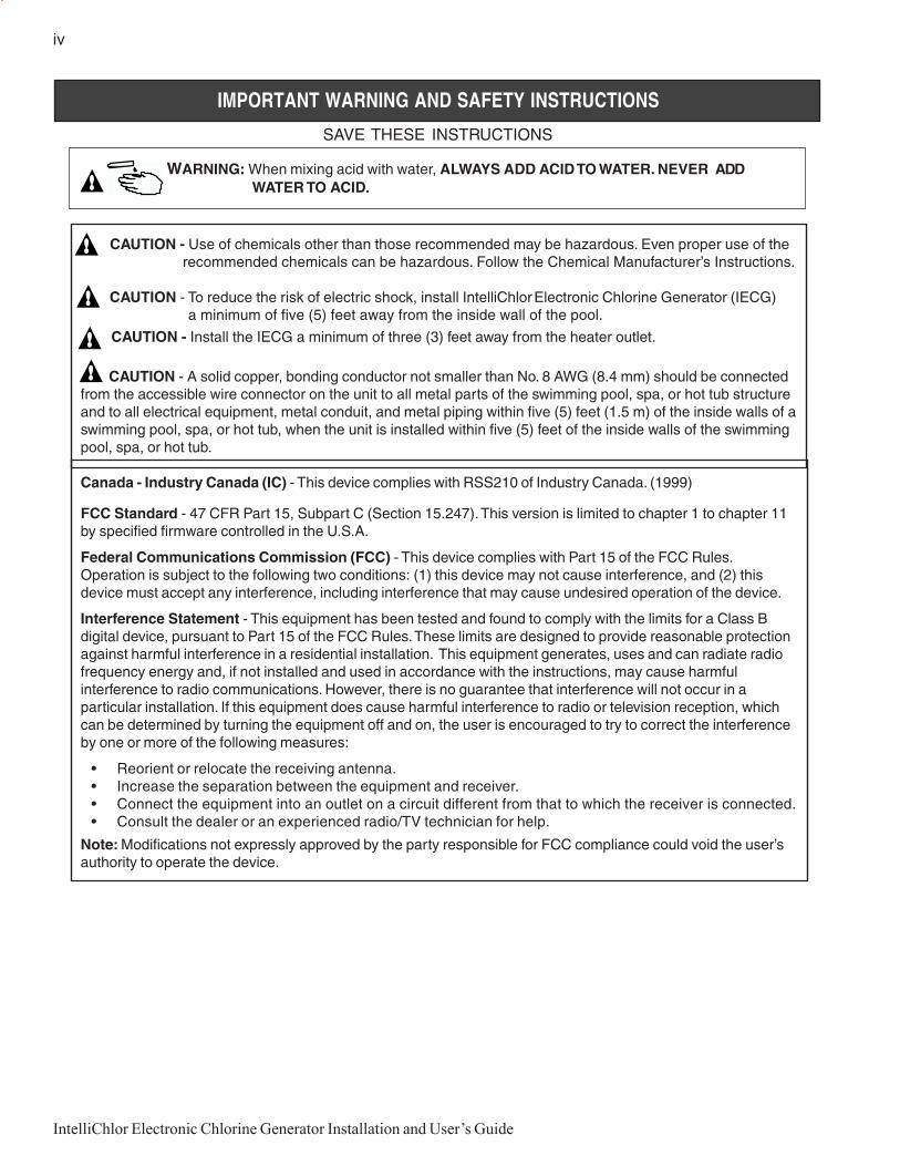
IMPORTANT WARNING AND SAFETY INSTRUCTIONS
CAUTION - Use of chemicals other than those recommended may be hazardous. Even proper use of the recommended chemicals can be hazardous. Follow the Chemical Manufacturer’s Instructions.
CAUTION - To reduce the risk of electric shock, install IntelliChlor Electronic Chlorine Generator (IECG) a minimum of five (5) feet away from the inside wall of the pool.
CAUTION - Install the IECG a minimum of three (3) feet away from the heater outlet.
CAUTION - A solid copper, bonding conductor not smaller than No. 8 AWG (8.4 mm) should be connectedfrom the accessible wire connector on the unit to all metal parts of the swimming pool, spa, or hot tub structureand to all electrical equipment, metal conduit, and metal piping within five (5) feet (1.5 m) of the inside walls of aswimming pool, spa, or hot tub, when the unit is installed within five (5) feet of the inside walls of the swimmingpool, spa, or hot tub.
Canada - Industry Canada (IC) - This device complies with RSS210 of Industry Canada. (1999)
FCC Standard - 47 CFR Part 15, Subpart C (Section 15.247). This version is limited to chapter 1 to chapter 11by specified firmware controlled in the U.S.A.
Federal Communications Commission (FCC) - This device complies with Part 15 of the FCC Rules.Operation is subject to the following two conditions: (1) this device may not cause interference, and (2) thisdevice must accept any interference, including interference that may cause undesired operation of the device.
Interference Statement - This equipment has been tested and found to comply with the limits for a Class Bdigital device, pursuant to Part 15 of the FCC Rules. These limits are designed to provide reasonable protectionagainst harmful interference in a residential installation. This equipment generates, uses and can radiate radiofrequency energy and, if not installed and used in accordance with the instructions, may cause harmfulinterference to radio communications. However, there is no guarantee that interference will not occur in aparticular installation. If this equipment does cause harmful interference to radio or television reception, whichcan be determined by turning the equipment off and on, the user is encouraged to try to correct the interferenceby one or more of the following measures:
• Reorient or relocate the receiving antenna.• Increase the separation between the equipment and receiver.• Connect the equipment into an outlet on a circuit different from that to which the receiver is connected.• Consult the dealer or an experienced radio/TV technician for help.
Note: Modifications not expressly approved by the party responsible for FCC compliance could void the user’sauthority to operate the device.
SAVE THESE INSTRUCTIONS
WARNING: When mixing acid with water, ALWAYS ADD ACID TO WATER. NEVER ADD WATER TO ACID.

1
IntelliChlor Electronic Chlorine Generator Installation and User’s Guide
IntelliChlor® Electronic Chlorine Generator Overview
The IntelliChlor® Electronic Chlorine Generator (IECG) salt chlorinator uses a process known as electrolysis toproduce chlorine gas which immediately dissolves into a solution to create Hypochlorite and Hypochlorous acidpool and spa water sanitizer from a low concentration of salt added to the pool water. Hypochlorite andHypochlorous kill bacteria, oxidizes organic material, and kills algae, then reverts back to salt. The IECG thenreuses the salt and the process starts over again. The IntelliChlor system is comprised of the IECG and PowerCenter.
CAUTION - The IntelliChlor Electronic Chlorine Generator (IECG) is designed only to produce chlorine. TheIECG does not monitor or control chlorine levels in the pool or spa water. It is the pool owner’s responsibility formonitoring and maintaining free chlorine levels at the APSP recommended range of 2.0 to 4.0 parts per million(ppm). It is the pool owner’s responsibility to check, on a regular basis, the free chlorine level while the poolpump is running, and adjust the IntelliChlor Electronic Chlorine Generator accordingly.
WARNING - Salt is an inherently corrosive material. While the levels of salt required for properoperation of the IntelliChlor Electronic Chlorine Generator are relatively low when compared to sea water andother salt solutions, placing any amount of salt in your pool increases the likelihood of corrosion or otherdeterioration of pool equipment and any surfaces used in and around your pool. Metal parts (including steelpools) and certain natural and man-made surfaces are particularly susceptible to corrosion and deteriorationwhen used in and around salt water pools. Pentair Water Pool and Spa (“Pentair”) does not represent orotherwise guarantee that the proper use of the IntelliChlor Electronic Chlorine Generator will prevent corrosion orother deterioration of pool equipment and any surfaces used in and around your pool. Consult your experiencedpool professional, who should be able to advise you on the proper material selection, installation techniques forthose materials, and the proper use, care and maintenance of those materials for your specific pool type andlocation in order to minimize the corrosion and deterioration that is inherent in and around salt water pools.
CAUTION - FOR ALL NEWLY CONSTRUCTED OR RESURFACED PLASTER POOLS: Do notoperate the IECG with newly poured or resurfaced pool plaster. Salt is a corrosive element and severesalt damage can occur to your pool. Wait at least ONE (1) MONTH after construction to allow plaster tocure before adding salt and operating IECG. Follow the pool surface manufacturer’s guidelines for yourspecific pool.FOR NEW VINYL LINER POOLS, contact the manufacturer for recommended guidelines before addingsalt and operating the IECG.
Replacement CIC60P and CIC60S Cell Part Numbers• CIC60P - P/N 521151• CIC60S - P/N 521005
Features• Superior design combines cell and control panel as one assembly.• Connects to ORP system via dry contact wires, to switch on or off based on chlorine demand.• Cell blades are made from a titanium metal base and coated with precious metal Ruthenium oxide.• Cell blades are capable of producing chlorine for at least 10,000 hours, when the IECG is used properly.• The IECG can be installed horizontally or vertically.• Separate Power Center mounts to wall at equipment pad, for easy AC wiring.• Electronics run cool for long, reliable life.• Cell hour meter reports current usage to determine how many hours remain in the life of the unit.• CIC60P and CIC60S cell produces up to 2.00 lbs of chlorine per 24 hours.• Head Loss of the IECG system installed into the main line is less than 1 psi.• Salt level LED indicators show three ranges for the amount of salt in pool.• Red and green LED indicators show system status for water flow, cell status and cold water.• MORE and LESS output buttons control how much chlorine is produced.• BOOST cycle sets the unit to maximum chlorine output for 24 hours of pump run time.• UL listed to UL1081 standards for swimming pool chlorinators.• Approved NSF regulatory standards, and CE certified.

2
IntelliChlor Electronic Chlorine Generator Installation and User’s Guide
IntelliChlor Commercial System Components
An IntelliChlor Commercial System components can be configured as follows:
• Stand-alone - No ORP: This system consists of one CIC60P cell, one PC100 power center, and nooxidation reduction potential (ORP) sensor/panel. Chlorine is dispensed on a timed basis, set by theMORE and LESS buttons on the cell.
• Stand-alone with ORP: This system consists of one CIC60P cell, one CPC100 power center, andan oxidation reduction potential (ORP) sensor/panel system (sold separately). The chlorine isdispensed on demand from the ORP sensor.
• Multi-Cell with ORP: This system consists of one CIC60P cell and multiple secondary cells,CIC60S, multiple power centers, and an oxidation reduction potential (ORP) sensor/panel system(sold separately). The chlorine is dispensed on demand from the ORP sensor. For multiple cellsystems, there is one CIC60P cell, labeled PRIMARY and additional CIC60S cells labeledSECONDARY. The SECONDARY cells communicate with the PRIMARY cell. Note: There canonly be one PRIMARY cell in a multiple cell system.
Acu-Trol panel with ORP sensor (sold separately)
The Acu-Trol panel contains an oxidation reduction potential (ORP) sensor that is placed in the water streamto detect the amount of sanitizing ability in the water and according to a user-preset trip point, calls for chlorinewhen low, and cancels chlorine when satisfied. This panel provides a dry-contact output that connects to theIntelliChlor system. When the dry-contact terminals are closed, chlorine is required. When the dry contactterminals are open, no chlorine is required. The Acu-Trol panel is not used for a stand-alone-No ORP system.
PC100 Commercial Power Center - No ORP
The PC100 commercial power center provides power to one CIC60P cell, but does not interconnect to anORP system. The CIC60P cell will operate on a timed basis, set by the MORE and LESS buttons on the cell.This system may be used with a time clock to control operations.
CPC100 Commercial Power Center with ORP
The CPC100 commercial power center, with ORP provides power to each cell. The power center labeledPRIMARY contains the dry-contact wires that connect to the external ORP system. When the dry-contactwires are closed, the “Primary” panel sends a 100% command to the cell; chlorine is being produced. Whenthe dry-contact wires are opened, the Primary panel sends a 0% output command to the cell, to stop producingchlorine.
Example 1:
Small hotel pool requires a two (2) lb. system.Equipment used: One CIC60P cell
One CPC100 power center (one power center)Acu-Trol panel with ORP sensor
Example 2:
Health club spa requires a four (4) lb. systemEquipment used: Use multiple-cell system COMSYS-4
Sizing:
To correctly size the chlorine requirements of a commercial pool, use the following rule:• Two (2) lbs. of chlorine per 10,000 gallons of water
To size a commercial spa, use this general rule:• One pound of chlorine per 2,000 gallons of water
These rules appear oversized, but ensure rapid chlorine make-up time, essential for commercial health codes.

3
IntelliChlor Electronic Chlorine Generator Installation and User’s Guide
IntelliChlor Electronic Chlorine Generator Control Panel and Cell Description
The IntelliChlor Electronic Chlorine Generator (IECG) includes a control panel with buttons and LEDindicators to control the IECG and produce chlorine. The IECG measures the water temperature and salt levelto produce chlorine at the defined output. If the salt level in the pool water is too low (red on salt display), thecell is turned off until salt is added to the pool. The controller has a self-cleaning cycle which reverses the cellpolarity, reducing calcium buildup. This feature turns the cell on and off at regular intervals to prevent calciumand scale buildup and further maximizes cell life.
The IECG contains the control electronics and bipolar electrodes that electrically produces chlorine whenenergized with DC current. Chlorine is generated as pool water containing salt passes through the cell. Thechlorine production can be varied by either adjusting the sanitizer output level on the control panel and/or byvarying the number of hours the IECG is on each day. The IECG automatically reverses the cell electrodeblades every few hours to help clean the cell. This process does not interrupt the production of Chlorine.The IECG also contains a mechanical flow sensor to ensure the proper amount of water is passing through thecell to allow chlorination to occur. The IECG automatically measures the water salinity and temperature anddisplays four (4) salinity ranges on the control panel using LED indicators. The IECG includes a 15 ft. ULapproved four conductor 16-gauge cable for connection to the Power Center.
• Flow Sensor: A flow sensor assures that there will always be adequate water flow through theIECG. If the IECG is not properly plumbed and/or does not receive adequate water flow, no chlorinewill be produced.
• Temperature Sensor: To protect the IECG from operation and potential damage when thetemperature of the pool water falls below 52° F, ±3° F (11° C, ±1.67° C), the temperature sensorswitches the IECG off, and no chlorine is being produced.
• Salt Sensor: Two salt sensor probes in the IECG are activated each time the IECG is switched onand again during every eight (8) hours of continuous running. At each of those times, the salt levelLED indicator lights flash in a scrolling sequence for two (2) minutes to indicate that the IECG is inanalysis mode. After two (2) minutes, the LED indicators lights will signal one (1) of four (4) salinityranges. For more information, see “Salt Level Status LEDs” on page 7.
Note: The salt sensor reading is within +/- 500 ppm accuracy.

4
IntelliChlor Electronic Chlorine Generator Installation and User’s Guide
IntelliChlor Power Center
The IntelliChlor Power Center converts AC electrical current to a low-voltage DC electrical current which isrequired to produce chlorine. The power supply is connected with the pool circulation pump electrical sourceso that the IECG only operates when the pool pump is on. The Power Center should be mounted vertically onthe wall up to fifteen (15) feet away from the IECG. The Power Center contains the transformer, fuse,connector to the cell and the AC electrical current wiring configuration with the DC electrical current outputcable to the IECG. A fuse holder is mounted on the bottom of the Power Center for additional protection.There are no other controls or lights on the Power Center. For information about installing and proper use ofthe Power Center, see the “IntelliChlor Power Center Installation Guide,” (P/N 520590).
IntelliChlor Power Center (Model PC 100 and CPC 100)
CAUTION - The IntelliChlorPower Center does NOT controlthe pump. The IntelliChlorElectronic Chlorine Generatoronly produces chlorine when thepool pump is on.
CAUTION - Before plugging orunplugging the IntelliChlor ElectronicChlorine Generator to the Power Center,first switch off the AC power to the PowerCenter.
CAUTION - Only plug CIC60P andCIC60S into PC100 or CPC100 PowerCenters. DO NOT plug into IntelliTouchEasyTouch, or SunTouch automationsystems with integrated power sources.This will cause the circuit breaker torepeatedly trip.
IntelliChlor Electronic Chlorine Generator
Clear slidingcover
Control Panelstatus LEDs
MORE and LESSoutput buttons

5
IntelliChlor Electronic Chlorine Generator Installation and User’s Guide
System Schematic Diagram
The following schematic diagram shows a typical IntelliChlor system installation.
Note: This schematic diagram is not drawn to scale. Refer to the relevant portions of this Installationand User’s Guide for information regarding proper placement and spacing of all equipment depicted inthis diagram.
NOT TO SCALE
Install Chlorine/Bromine Feeders after the IntelliChlor Cell
CAUTION - To avoid permanent damage to the IntelliChlor cell, automatic in-line chlorine/bromine feeders(such as Pentair Water Pool and Spa® Rainbow™ models) MUST be installed AFTER the IntelliChlor cell asshown below. When using the IntelliChlor with an in-floor cleaner pressure system, it is recommended that aseparate return line be used for the cleaner to reduce the increased water pressure stress on the IntelliChlorcell.
Note: For best flowsensing, provide atleast 12"-18" of straightpipe in front of the cellinlet.

6
IntelliChlor Electronic Chlorine Generator Installation and User’s Guide
NOT TO SCALE
Note: For best flowsensing, provide atleast 12"-18" of straightpipe in front of the cellinlet.
IntelliChlor Plumbing Diagram (For single CIC60P cell system)
Plumbing the IntelliChlor Electronic Chlorine Generator (IECG) for a single CIC60P cell system:
• Always install the IntelliChlor Electronic Chlorine Generator AFTER the filter and heater (see“System Diagram” on page 4). The ICEG should be no closer than three (3) feet away from theheater outlet.
• If the IECG is installed on a pool/spa combination system, install (see diagram below) the IECGBEFORE the pool/spa return valve to allow proper chlorination of both the pool and spa and also toavoid creating gas traps in the pipes.
Note: If a multiple cell system is used, refer to the Installation guide for that system. The kit comes withprepared plumbing manifolds.
Loop Plumbing Diagram (For single CIC60 cell system)
The IntelliChlor Electronic Chlorine Generator is designed to operate with water flow rates from 25 gallons perminute (gpm) up to 105 gpm. Do not exceed 105 gpm or pipe manufacturers recommended flow rate,whichever is less. For flow rates over 80 gpm, it is recommend that you use a bypass loop (as shown below)for best chlorine production. Installations with flow rates over 80 gallons per minute are those that havein-floor cleaning systems or booster pumps. These single CIC60 cell systems should use a bypass loop with theIECG with a flow control valve that assures that the flow through the IECG is maintained within its designedoperating water flow rates.
Note: Single CIC60 cell system. NOT FOR MULTIPLE CELL SYSTEMS.
NOT TO SCALE
F lo w c o n tro l v a lve
Bypass loopIN
TELL
ICH
LOR
ELEC
TRO
NIC
CH
LORI
NE
GEN
ERA
TOR
VALVEFLOW IN FLOW OUT
FLOW IN
FLOW OUT
“UPWARD FLOW”

7
IntelliChlor Electronic Chlorine Generator Installation and User’s Guide
G REEN
RED
Salt Level
StatusC old Water
Ma xMin
o tB o s
Low
Sanitizer Output
/OOn �
F low
C ell
MoreLess
40% 60% 80%20% 100%
for 24 hour 100% output
G REEN
Press both buttons simultaneously
- good
Good - good salt- high salt
- low salt- add salt
-System Off
- inspect cell
- no flow - good flow
FLASHINGG REEN
FLASHING
(System off )
RED
NS FR
ACID CLEAN EVERY 3 MONTHS
IDEAL SALT 3400 ppm
www.intellichlor.net
system off
SWIMMING POOL ANDSPA CHLORINATOR30ZR Certified to
NSF/ANSI Standard 50
Section 1IntelliChlor Control Panel
Salt Level Status LEDsThe IECG salt level checks the pool water daily and displays the levels asfollows:
Green LED: Good salt. The pool water salt level is between 3300 ppm and5000, and the IECG is producing chlorine. IECG salt LED should always beshowing GREEN level for better results.
Green LED (Flashing): Salt level is above 5000 ppm. Chlorine is beingproduced but the salt level is too high which increases the risk of corrosionand deterioration of pool equipment and surfaces in and around the pool. Poolwater needs to be drained and refilled one (1) foot at a time until the saltlevel is below 5000 ppm.
Red LED: Low salt. The water salt level is below 3300 ppm. The IECG willbe producing chlorine at reduced efficiency. It is highly recommended to addsalt. See (*) Note below.
Red LED: Very low salt. The water salt level has fallen below 2600 ppm. TheIECG will not produce chlorine until salt is added. The IECG is OFF.See (*) Note below.
NOTE (*): After every salt addition, pump should be allowed to run for at least 24 hours for proper dilution. Salinity readings should only be taken, after the dilution period.
DO NOT take salinity readings during the dilution period, otherwise readings WILL NOT be accurate.
Status LEDsCold Water: Shows the IntelliChlor Electronic Chlorine Generator powerstatus:• No Light: .The IECG is operating in the normal temperature range (>
52° F)
• Red: The IECG is in “Standby” mode (system off, no chlorineproduction) due to a cold water condition. The IECG will resume tonormal operation mode, including accurate salinity report, oncewater temperature goes above 52° F.
Cell: Shows the status of the IECG.• Green (flashing): The IECG needs to be inspected. The blades may have calcium buildup. The IECG
is not producing chlorine.
• Green: IECG is good and producing chlorine
No Light: IECG is off and not producing chlorine. It may be in an off-period of the sanitizing cycle andwill return on shortly.
Flow: This light indicates the status of water flowing through the IECG.• Red: Insufficient water flow through the IECG, no chlorine is being produced.
• Green: Sufficient water flow to produce chlorine.
8
IntelliChlor Electronic Chlorine Generator Installation and User’s Guide
Operator Control Panel (continued)
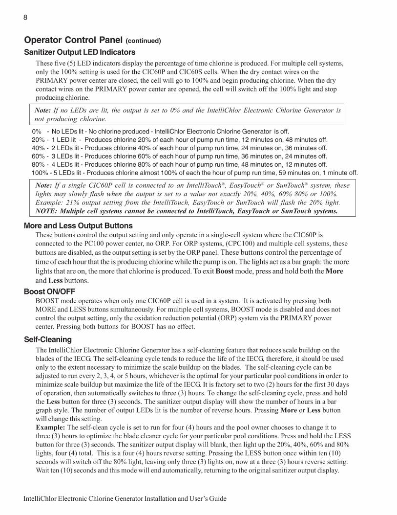
Sanitizer Output LED IndicatorsThese five (5) LED indicators display the percentage of time chlorine is produced. For multiple cell systems,only the 100% setting is used for the CIC60P and CIC60S cells. When the dry contact wires on thePRIMARY power center are closed, the cell will go to 100% and begin producing chlorine. When the drycontact wires on the PRIMARY power center are opened, the cell will switch off the 100% light and stopproducing chlorine.
Note: If a single CIC60P cell is connected to an IntelliTouch®, EasyTouch® or SunTouch® system, theselights may slowly flash when the output is set to a value not exactly 20%, 40%, 60% 80% or 100%.Example: 21% output setting from the IntelliTouch, EasyTouch or SunTouch will flash the 20% light.NOTE: Multiple cell systems cannot be connected to IntelliTouch, EasyTouch or SunTouch systems.
More and Less Output ButtonsThese buttons control the output setting and only operate in a single-cell system where the CIC60P isconnected to the PC100 power center, no ORP. For ORP systems, (CPC100) and multiple cell systems, these
buttons are disabled, as the output setting is set by the ORP panel. These buttons control the percentage oftime of each hour that the is producing chlorine while the pump is on. The lights act as a bar graph: the morelights that are on, the more that chlorine is produced. To exit Boost mode, press and hold both the Moreand Less buttons.
Boost ON/OFFBOOST mode operates when only one CIC60P cell is used in a system. It is activated by pressing bothMORE and LESS buttons simultaneously. For multiple cell systems, BOOST mode is disabled and does notcontrol the output setting, only the oxidation reduction potential (ORP) system via the PRIMARY powercenter. Pressing both buttons for BOOST has no effect.
Note: If no LEDs are lit, the output is set to 0% and the IntelliChlor Electronic Chlorine Generator isnot producing chlorine.
Self-CleaningThe IntelliChlor Electronic Chlorine Generator has a self-cleaning feature that reduces scale buildup on theblades of the IECG. The self-cleaning cycle tends to reduce the life of the IECG, therefore, it should be usedonly to the extent necessary to minimize the scale buildup on the blades. The self-cleaning cycle can beadjusted to run every 2, 3, 4, or 5 hours, whichever is the optimal for your particular pool conditions in order tominimize scale buildup but maximize the life of the IECG. It is factory set to two (2) hours for the first 30 daysof operation, then automatically switches to three (3) hours. To change the self-cleaning cycle, press and holdthe Less button for three (3) seconds. The sanitizer output display will show the number of hours in a bargraph style. The number of output LEDs lit is the number of reverse hours. Pressing More or Less buttonwill change this setting.Example: The self-clean cycle is set to run for four (4) hours and the pool owner chooses to change it tothree (3) hours to optimize the blade cleaner cycle for your particular pool conditions. Press and hold the LESSbutton for three (3) seconds. The sanitizer output display will blank, then light up the 20%, 40%, 60% and 80%lights, four (4) total. This is a four (4) hours reverse setting. Pressing the LESS button once within ten (10)seconds will switch off the 80% light, leaving only three (3) lights on, now at a three (3) hours reverse setting.Wait ten (10) seconds and this mode will end automatically, returning to the original sanitizer output display.
0% - No LEDs lit - No chlorine produced - IntelliChlor Electronic Chlorine Generator is off. 20% - 1 LED lit - Produces chlorine 20% of each hour of pump run time, 12 minutes on, 48 minutes off. 40% - 2 LEDs lit - Produces chlorine 40% of each hour of pump run time, 24 minutes on, 36 minutes off. 60% - 3 LEDs lit - Produces chlorine 60% of each hour of pump run time, 36 minutes on, 24 minutes off. 80% - 4 LEDs lit - Produces chlorine 80% of each hour of pump run time, 48 minutes on, 12 minutes off. 100% - 5 LEDs lit - Produces chlorine almost 100% of each the hour of pump run time, 59 minutes on, 1 minute off.

9
IntelliChlor Electronic Chlorine Generator Installation and User’s Guide
Section 2Pool Water Chemistry, Conditions
and PrecautionsThis section describes the start up procedure and operating instructions for IntelliChlor Electronic ChlorineGenerator.
Pool Water Chemistry, Conditions and Precautions1. New Pool Water: A recently filled or newly-refinished pool may contain undesirable matter. This
undesirable matter could interfere with IntelliChlor’s ability to chlorinate properly. Make sure thewater is tested by a pool professional and properly balanced before switching on the IntelliChlorElectronic Chlorine Generator.
WARNING - Salt is an inherently corrosive material. While the levels of salt required for proper operation ofthe IntelliChlor Electronic Chlorine Generator are relatively low when compared to sea water and other saltsolutions, placing any amount of salt in your pool increases the likelihood of corrosion or other deterioration ofpool equipment and any surfaces used in and around your pool. Metal parts and certain natural and man-madesurfaces are particularly susceptible to corrosion and deterioration when used in and around salt water pools.Pentair Water Pool and Spa does not represent or otherwise guarantee that the proper use of the IntelliChlorElectronic Chlorine Generator will prevent corrosion or other deterioration of pool equipment and any surfacesused in and around your pool. Consult your experienced pool professional, who should be able to advise you onthe proper material selection, installation techniques for those materials, and the proper use, care andmaintenance of those materials for your specific pool type and location in order to minimize the corrosion anddeterioration that is inherent in and around salt water pools.
2. Super Chlorination burns out the swimmer waste that has combined with chlorine. This frees thechlorine for sanitizing. This is accomplished by raising the chlorine level quickly and dramatically.When the chlorine level is raised to ten (10) times the amount of combined chlorine (usually 5 to 10ppm) the pool water is said to have been super chlorinated. As pool water is continuously passedthrough the IECG while the unit is powered on, all pool water inside the IECG is being superchlorinated. When the IntelliChlor Electronic Chlorine Generator is used on pools, the pool watersparkles and does not burn the eyes because of the absence of chloramines.Note: On initial start-up of a pool, it is best to super chlorinate using an outside source, i.e.,use a shock treatment available at your local pool supplier.
3. Chloramines should not be present in pool water. Chloramines are formed when ammonia (which isfound in urine and sweat) combine with free chlorine. This ties up the free chlorine in your pool anddoes not allow the chlorine in your pool to disinfect. Chloramines also burn the eyes and are foulsmelling. Super Chlorinate to remove chloramines at the initial start-up of the pool and as needed tomaintain proper levels of free chlorine.
4. Cyanuric acid is needed in outdoor pools to help to stabilize and maintain proper levels of chlorine.90% of unstabilized chlorine is destroyed by the UV radiation from the sun within two hours.Cyanuric acid stabilizes chlorine in water from UV degradation. When using the IECG, the cyanuricacid level should be maintained between 50-80 ppm. See Table 3, on page 14. NOTE: DO NOT USECYANURIC ACID IN INDOOR POOLS.
5. Total Dissolved Solids (TDS): Adding salt to pool water will raise the TDS level. While this doesnot adversely affect the pool water chemistry or clarity, the pool water professional testing for TDSmust be made aware salt has been added to the IntelliChlor system. The individual performing theTDS test (see page 22) may then subtract the salinity level to arrive at a TDS level that would becompatible to a TDS reading for a non-salt water pool.

10
IntelliChlor Electronic Chlorine Generator Installation and User’s Guide
6. Metals - Some metals, i.e. copper and iron, can cause loss of chlorine. Also, metals can stain yourpool. Metals can also damage the IntelliChlor Electronic Chlorine Generator. Have your local poolprofessional check for metals and recommend methods of removal.
7. Nitrates and Phosphates can cause extremely high chlorine demands and will deplete chlorine fromyour swimming pool. In some cases nitrates may even lower your chlorine levels to zero. Your localpool professional can test for nitrates and phosphates. While a 0 ppm level of nitrates is the ideal, thepool owner should make sure that nitrates DO NOT exceed 10 ppm. Phosphates should not exceed125 parts per billion (ppb).
Optimum Pool Water Chemistry Conditions for Salt Water Pools(using the IntelliChlor Electronic Chlorine Generator)
In accordance with the Association of Pool and Spa Professionals (APSP) standards, it is recommended thatthe following pool water chemistry conditions be maintained on an on going basis to help protect pool users,pool related equipment and surfaces in and around the pool. These values are important to maintaining the poolequipment in proper operating condition and preventing corrosion, liming or other problems. The IntelliChlorElectronic Chlorine Generator is warranted to operate properly only if these conditions are met. For moreinformation, refer to your local agency having jurisdiction, NSPI (National Spa and Pool Institute), the CDC(Centers for Disease Control), or the WHO (World Health Organization).
Free Chlorine: 2.0 - 4.0 ppm. Above 4.0 ppm may cause corrosion of metal components
Combined Chlorine (Chloramines): None (super chlorinate to remove all chloramines)
pH: 7.2 - 7.8 (USE MURIATIC ACID to lower pH and Soda Ash to raise pH.)
Cyanuric Acid: 30 - 50 ppm
Total Alkalinity: 80 - 120 ppm
Calcium Hardness: 200 - 400 ppm
TDS (includes salt): 3000 minimum to 5700 to 6000 maximumppm
Salt: 3300 - 5000 ppm (ideal 3800 ppm)
Metals (Copper, Iron, Manganese): None
Nitrates: None
Phosphates: Less than 125 ppb
Saturation Index -.3 to .3 (zero (0) best)
Covered Pools and Vinyl Liner Pool and Lowering Chlorine Output LevelsWhen using the IntelliChlor Electronic Chlorine Generator with covered pools and/or vinyl liner pools, lesschlorine is needed. It is recommend to lower the chlorine output level while the pool is covered. For moreinformation about chlorine output levels, refer to the instructions with the external ORP sensor system to lowerthe chlorine output.
11
IntelliChlor Electronic Chlorine Generator Installation and User’s Guide
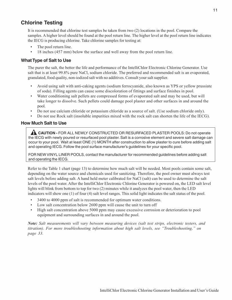
Chlorine TestingIt is recommended that chlorine test samples be taken from two (2) locations in the pool. Compare thesamples. A higher level should be found at the pool return line. The higher level at the pool return line indicatesthe IECG is producing chlorine. Take chlorine samples for testing at:• The pool return line.• 18 inches (457 mm) below the surface and well away from the pool return line.
What Type of Salt to Use
The purer the salt, the better the life and performance of the IntelliChlor Electronic Chlorine Generator. Usesalt that is at least 99.8% pure NaCl, sodium chloride. The preferred and recommended salt is an evaporated,granulated, food quality, non-iodized salt with no additives. Consult your salt supplier.
• Avoid using salt with anti-caking agents (sodium ferrocyanide, also known as YPS or yellow prussiateof soda). Filling agents can cause some discoloration of fittings and surface finishes in pool.
• Water conditioning salt pellets are compressed forms of evaporated salt and may be used, but willtake longer to dissolve. Such pellets could damage pool plaster and other surfaces in and around thepool.
• Do not use calcium chloride or potassium chloride as a source of salt. (Use sodium chloride only).• Do not use Rock salt (insoluble impurities mixed with the rock salt can shorten the life of the IECG).
How Much Salt to Use
Refer to the Table 1 chart (page 13) to determine how much salt will be needed. Most pools contain some salt,depending on the water source and chemicals used for sanitizing. Therefore, the pool owner must always testsalt levels before adding salt. A hand held meter calibrated for NaCl (salt) can be used to determine the saltlevels of the pool water. After the IntelliChlor Electronic Chlorine Generator is powered on, the LED salt levellights will blink from bottom to top for two (2) minutes while it analyzes the pool water, then the LEDindicators will show one (1) of four (4) salt level ranges. This solid light indicates the salt status of the pool.• 3400 to 4000 ppm of salt is recommended for optimum water conditions.• Low salt concentration below 2600 ppm will cause the unit to turn off• High salt concentration above 5000 ppm may cause excessive corrosion or deterioration to pool
equipment and surrounding surfaces in and around the pool.
Note: Salt measurements will vary between measuring devices (salt test strips, electronic testers, andtitration). For more troubleshooting information about high salt levels, see “Troubleshooting,” onpage 33.
CAUTION - FOR ALL NEWLY CONSTRUCTED OR RESURFACED PLASTER POOLS: Do not operatethe IECG with newly poured or resurfaced pool plaster. Salt is a corrosive element and severe salt damage canoccur to your pool. Wait at least ONE (1) MONTH after construction to allow plaster to cure before adding saltand operating IECG. Follow the pool surface manufacturer’s guidelines for your specific pool.
FOR NEW VINYL LINER POOLS, contact the manufacturer for recommended guidelines before adding saltand operating the IECG.

12
IntelliChlor Electronic Chlorine Generator Installation and User’s Guide
Calculating the Saturation Index
The saturation index is a formula that relates pH, calcium and alkalinity in the pool water. A well balancedpool water will have a formula result range between -0.3 and 0.3 Outside this range, the pool water is out of
balance, potentially damaging pool equipment or scaling the IECG. The equation to calculate Si is:
Cyanuric acid in the form of cyanurate ions contribute to alkalinity. Thus, a correction must be made to totalalkalinity. We subtract 1/3 of the cyanuric acid level from the reading obtained in the total alkalinity test.
Total Alkalinity - 1/3 Cyanuric Acid = Corrected Alkalinity
This correction can be considerable in established pools with high cyanuric acid levels; for example, at 240ppm cyanuric acid, the correction amounts to 80 ppm (240 ÷ 3 = 80).
SI = pH + CHF + AF + TF + TDSFSaturationIndex
pH astested
CalciumHardnessFactor
AlkalinityFactor
Tempera-tureFactor
TDSFactor
Langelier Saturation Index Factors
TDS Factor
<1000 12.101000 12.192000 12.293000 12.354000 12.415000 12.44
TDS Factor (Factors shown below are based on the actual measured value for the particular parameter)

13
IntelliChlor Electronic Chlorine Generator Installation and User’s Guide
How to Add Salt to the Pool
CAUTION - FOR ALL NEWLY CONSTRUCTED OR RESURFACED PLASTER POOLS: Do not operatethe IECG with newly poured or resurfaced pool plaster. Salt is a corrosive element and severe salt damage canoccur to your pool. Wait at least ONE (1) MONTH after construction to allow plaster to cure before adding saltand operating IECG. Follow the pool surface manufacturer’s guidelines for your specific pool. FOR NEW VINYLLINER POOLS, contact the manufacturer for recommended guidelines before adding salt and operating theIECG.
1. Switch on the pump to circulate the pool water.2. Check salt level in pool water before adding any salt to pool.3. Determine the amount of salt from the following charts.4. Slowly pour in the salt around the outer perimeter of the pool for quick and even distribution. To
avoid clogging the filter or damaging pool related equipment and surrounding surfaces, do notadd salt through the skimmer or surge tank.
5. Brush the pool bottom and allow water to circulate for 24 hours to dissolve salt completely.6. After 24 hours, verify correct salt level reading by checking the LED indicators on the IntelliChlor
Electronic Chlorine Generator and by a separate reliable test method.7. Power on the IntelliChlor Electronic Chlorine Generator and set the external ORP system to the
proper setting to maintain the appropriate free chlorine levels in the pool water (i.e., within the2.0 - 4.0 ppm, APSP recommended range).
Table 1. Approximate Pounds (Kg) of salt needed to obtain 3,400 ppm in pool
MPP0043OTTLASFONOITIDDAROFTRAHC
looPsnollaG
mpp0 mpp052 mpp005 mpp057 mpp0001 mpp0521 mpp0051 mpp0571 mpp0002 mpp0522 mpp0052
000,01bl092 bl762 bl442 bl122 bl191 bl861 bl541 bl221 bl99 bl07 bl64
gk231 gk121 gk111 gk001 gk78 gk67 gk66 gk55 gk54 gk23 gk12
000,21bl843 bl023 bl292 bl562 bl032 bl202 bl471 bl641 bl811 bl48 bl65
gk851 gk541 gk331 gk021 gk401 gk29 gk97 gk66 gk45 gk83 gk52
000,41bl604 bl473 bl143 bl903 bl862 bl632 bl302 bl171 bl831 bl79 bl56
gk481 gk071 gk551 gk041 gk221 gk701 gk29 gk77 gk36 gk44 gk92
000,61bl464 bl724 bl093 bl353 bl603 bl962 bl232 bl591 bl851 bl111 bl47
gk112 gk491 gk771 gk061 gk931 gk221 gk501 gk88 gk27 gk15 gk43
000,81bl225 bl084 bl934 bl793 bl543 bl303 bl162 bl912 bl871 bl521 bl48
gk732 gk812 gk991 gk081 gk651 gk731 gk811 gk99 gk18 gk75 gk83
000,02bl085 bl435 bl784 bl144 bl383 bl733 bl092 bl442 bl791 bl931 bl39
gk362 gk242 gk122 gk002 gk471 gk351 gk231 gk111 gk98 gk36 gk24
000,22bl836 bl785 bl635 bl584 bl124 bl073 bl913 bl862 bl712 bl351 bl201
gk092 gk662 gk342 gk022 gk191 gk861 gk541 gk221 gk89 gk96 gk64
000,42bl696 bl146 bl585 bl925 bl064 bl404 bl843 bl292 bl732 bl761 bl111
gk613 gk192 gk562 gk042 gk802 gk381 gk851 gk331 gk701 gk67 gk15
000,62bl457 bl496 bl436 bl375 bl894 bl834 bl773 bl713 bl652 bl181 bl121
gk243 gk513 gk782 gk062 gk622 gk891 gk171 gk441 gk611 gk28 gk55
000,82bl218 bl747 bl286 bl716 bl635 bl174 bl604 bl143 bl672 bl591 bl031
gk863 gk933 gk013 gk082 gk342 gk412 gk481 gk551 gk521 gk88 gk95
000,03bl078 bl108 bl137 bl266 bl475 bl505 bl534 bl663 bl692 bl902 bl931
gk593 gk363 gk233 gk003 gk162 gk922 gk791 gk661 gk431 gk59 gk36

14
IntelliChlor Electronic Chlorine Generator Installation and User’s Guide
Table 3. Approximate amount of cyanuric acid to obtain 75 ppm in pool
NOTE: The cyanuric acid reading should be maintained at 50 - 80 ppm.
)sretil(snollagnieziSlooP
rezilibatSleveLerofeB
noitiddA
000,01)000,83(
000,21)000,54(
000,41)000,35(
000,61)000,06(
000,81)000,86(
000,02)000,67(
000,22)000,38(
000,42)000,19(
000,62)000,89(
000,82)000,601(
000,03)000,31(
mpp0sbl52.6)gk8.2(
sbl05.7)gk4.3(
sbl57.8)gk4(
sbl0.01)gk5.4(
sbl52.11)gk5(
sbl5.21)gk7.5(
sbl57.31)gk2.6(
sbl0.51)gk8.6(
sbl3.61)gk4.7(
sbl5.71)gk9.7(
sbl57.81)gk5.8(
mpp01sbl04.5)gk5.2(
sbl05.6)gk9.2(
sbl06.7)gk5.3(
sbl06.8)gk9.3(
sbl57.9)gk4.4(
sbl8.01)gk5(
sbl09.11)gk4.5(
sbl9.21)gk8.5(
sbl0.41)gk3.6(
sbl2.51)gk9.6(
sbl52.61)gk4.7(
mpp02sbl06.4
)gk2(sbl05.5)gk5.2(
sbl04.6)gk9.2(
sbl03.7)gk3.3(
sbl52.8)gk7.3(
sbl02.9)gk1.4(
sbl0.01)gk5.4(
sbl9.01)gk9.4(
sbl9.11)gk4.5(
sbl8.21)gk8.5(
sbl57.31)gk2.6(
mpp03sbl57.3)gk7.1(
sbl05.4)gk2(
sbl52.5)gk4.2(
sbl00.6)gk7.2(
sbl57.6)gk3(
sbl05.7)gk4.3(
sbl52.8)gk7.3(
sbl00.9)gk4(
sbl57.9)gk4.4(
sbl5.01)gk8.4(
sbl57.11)gk3.5(
mpp04sbl09.2)gk3.1(
sbl05.3)gk6.1(
sbl00.4)gk8.1(
sbl06.4)gk2(
sbl52.5)gk4.2(
sbl08.5)gk6.2(
sbl04.6)gk9.2(
sbl09.6)gk1.3(
sbl85.7)gk4.3(
sbl02.8)gk7.3(
sbl57.8)gk4(
mpp05sbl00.2
)gk1(sbl05.2)gk1.1(
sbl09.2)gk3.1(
sbl03.3)gk5.1(
sbl57.3)gk7.1(
sbl01.4()gk9.1(
sbl06.4)gk2(
sbl09.4)gk2.2(
sbl04.5)gk4.2(
sbl08.5)gk6.2(
sbl52.6)gk8.2(
mpp06sbl52.1)gk5.0(
sbl05.1)gk7.0(
sbl57.1)gk8.0(
sbl00.2)gk1(
sbl52.2)gk1(
sbl05.2)gk1.1(
sbl57.2)gk2.1(
sbl00.3)gk4.1(
sbl52.3)gk5.1(
sbl05.3)gk6.1(
sbl57.3)gk7.1(
mpp07sbl04.0)gk2.0(
sbl05.0gk2.0(
sbl06.0)gk3.0(
sbl66.0)gk3.0(
sbl57.0)gk3.0(
sbl08.0)gk4.0(
sbl09.0)gk4.0(
sbl00.1)gk4.0(
sbl01.1)gk5.0(
sbl02.1)gk5.0(
sbl52.1)gk6.0(
mpp57sbl0.0)gk0(
sbl0.0)gk0(
sbl0.0)gk0(
sbl0.0)gk0(
sbl0.0)gk0(
sbl0.0)gk0(
sbl0.0)gk0(
sbl0.0)gk0(
sbl0.0)gk0(
sbl0.0)gk0(
sbl0.0)gk0(
Table 2. Approximate amount of stabilizer (cyanuric acid) to obtain 40 ppm in pool
tnerruCdicAcirunayC
mpp-leveL
g000,01)L000,83(
g000,21)L524,54(
g000,41)L000,35(
g000,61)L006,06(
g000,81)L731,86(
g000,02)L000,67(
g000,22)L003,38(
g000,42)L058,09(
g000,62)L124,89
g000,82)L000,601
g000,03)L000,431(
0 )gk74.1(52.3 )gk77.1(09.3 )gk6.2(55.4 )gk63.2(02.5 )gk56.2(58.5 )gk49.2(05.6 )gk42.3(51.7 )gk35.3(08.7 )gk38.3(54.8 )gk21.4(01.9 )gk24.4(57.9
01 )gk01.1(34.2 )gk23.1(29.2 )gk45.1(04.3 )gk67.1(98.3 )gk89.1(73.4 )gk02.2(68.4 )gk24.2(53.5 )gk46.2(38.5 )gk68.2(23.6 )gk80.3(08.6 )gk03.3(92.7
02 )gk37.0(26.1 )gk88.0(49.1 )gk30.1(72.2 )gk71.1(95.2 )gk23.1(29.2 )gk74.1(42.3 )gk16.1(65.3 )gk67.1(98.3 )gk19.1(12.4 )gk50.2(45.4 )gk02.2(68.4

15
IntelliChlor Electronic Chlorine Generator Installation and User’s Guide
Pool Water Preparation
Determining Pool Size (Gallons of Water in Your Pool)
• Rectangular Pools: Length x width x average depth x 7.5
• Circular Pools: Diameter x diameter x average depth x 5.9
• Oval Pools: Length x width x average depth x 6.7
• Sloping Sides: Multiply total gallons by 0.85 = gallon capacity
Determining Pool Size (liters of water in your pool)
• Rectangular Pools: Length x width (meters) x average depth x 1000
• Circular Pools: Diameter x diameter x average depth x 785
• Oval Pools: Length x width (meters) x average depth x 893
• Sloping Sides: Multiply total liters by 0.85 = liter capacity.
CAUTION - Never use dry acid (sodium bisulfate) to adjust pH in arid geographic areas with excessiveevaporation and minimal dilution of pool water with fresh water. A buildup of byproducts can damage the IECG.

16
IntelliChlor Electronic Chlorine Generator Installation and User’s Guide
Blank Page

17
IntelliChlor Electronic Chlorine Generator Installation and User’s Guide
Section 3Operating IntelliChlor
This section describes the start up procedure and operating instructions for IntelliChlor Electronic ChlorineGenerator (IECG).
Before starting up and operating the IECG, the pool in which the IECG will be used must have been completedand filled with water for at least one (1) month and the pool water salt level must be stable and beingmaintained at 3,300 to 5,000 ppm.
Initial Start up PeriodFor the first thirty (30) days of cell operation, the self-cleaning cycle, is factory set to two (2) hours. Afterthirty (30) days has elapsed, the IECG will automatically set itself to four (4) hour self-cleaning cycle. Thisfeature will clean the IECG blades more often during the initial installation, then go to a more standard self-cleaning cycle for longer blade life.
Operation
Use of an external Pool Pump Timer
The CIC60 cell and power center is designed to interface with an external ORP system that monitors thechlorine levels in the pool or spa and calls for chlorine production as needed to maintain the preset ORPsettings. Note: If using the CIC60P as a stand-alone - No ORP system, a pool pump timer may be used.
CAUTION - The IECG is designed only to produce chlorine. The IECG does not monitor or control chlorinelevels in the pool or spa; the ORP system monitors chlorine, and calls for it as needed. The pool owner or sitetechnician is responsible for monitoring and maintaining free chlorine levels in the pool/spa according to APSPrecommendations on a daily basis and adjust sanitizer level on the ORP system accordingly.
CAUTION - Before attempting to operate IntelliChlor refer to “General Recommendations and GeneralCautions,” on page 19, and “Pool Water Preparation,” on page 15. Also, do not adjust Sanitizer Output above20% until it is certain that salt has been dissolved in pool. Operating without salt will result in the unit turning offand lighting the CHECK SALT light on the salt display. No chlorine will be produced until salt is added to thepool.
If you use a Pool Pump Timer
The Association of Pool and Spa Professionals (APSP) recommends that all water in a residential pool passthrough the filtration system at least once every twelve (12) hours (referred to as pool water turnover).However, many factors have an effect on actual pump and filter system run times. Pool size, source of water,direct sun light, indoor/outdoor, screened/unscreened, filtration system, cold or hot weather, swimmer load, rain,organic debris, algae, etc., are all factors which contribute to either more or less pool pump and filter systemrun times. Because of these differences, it is extremely difficult to set a standard initial run time (starting point)for the pool pump and chlorinating system.
Try initially setting the pool pump timer to twelve (12) hours. It will take a few days to achieve the correctamount of pool pump operating time. When IntelliChlor is wired with a pool pump timer results will varygreatly from one pool installation to the next, so this should be discussed with your poolprofessional. The key points are: (continue on next page)

18
IntelliChlor Electronic Chlorine Generator Installation and User’s Guide
• Operate the pool pump at least the minimum time needed for good filtration and adequate chlorineproduction by the IECG, according to your pool professional’s recommendations.
• While pool pump timers can reduce energy consumption, the pool pump must be running for theIntelliChlor Electronic Chlorine Generator to provide chlorine and must remain running long enough tomaintain proper chlorine levels (i.e., 2.0 - 4.0 ppm of free available chlorine).
Note: Exception - For Cold Weather Operation: The unit turns off in water temperatures of 52° F, ±3° F(11° C, ±1.67° C) and below, and will not produce chlorine. This feature extends the life of the cell.
Start-up Procedure (Super Chlorination)
Super Chlorination is recommended before pool start-up. Start out with clean, properly chlorinated, poolwater from the beginning. The IECG will build up a sufficient level of chlorine for sanitation in several hours.However, if the pool water has a high demand from the start-up the IECG will not be able to produce enoughchlorine to reach break-point chlorination. So, it is best to super chlorinate using an outside source at the timeof pool start-up. Then, wait until the chlorine level has returned to 2.0 to 4.0 ppm before switching on theIECG.
Sanitizer Output Settings and Adjustments
• Switch on the pool pump switch or pool pump timer. The IntelliChlor control panel green PWR powerLED light should be on. The salt display will blink all three (3) LEDs (bottom to top) for two (2)minutes, indicating that it has not checked the salt level yet. After two (2) minutes, the salt will bechecked and one (1) of the four (4) salt level LEDs will be displayed. If the salinity is below 2600ppm, the salt display will light the red LOW SALT indicator, and the CELL light will go blank,indicating there is not enough salt in the pool for chlorine to be produced.
• Set the ORP system to the desired level of chlorine.
• If using as a stand-alone - No ORP system, use the MORE or LESS buttons on the cell to set theoutput to 60% as a starting point.
• After 24 hours, use a reliable test method to test the pool water for free available chlorine. The idealrange to maintain is 2.0-4.0 ppm. If the free chlorine level of the pool water is too low,increase chlorine production by adjusting the ORP level on the ORP panel. If the freechlorine level of the pool water is too high, decrease chlorine production by adjusting theORP level on the ORP panel.
• If operating as a stand-alone- No ORP system, press the MORE or LESS buttons on the cell to adjustthe chlorine output accordingly.
• Due to a varying free chlorine demand of pool water, it may take a few days to determine the numberof daily pool operating hours and “Sanitizer Output” percentage setting (see page 8) for your pool.Continue adjusting as necessary, allowing 24 hours between adjustments until the free chlorine levelof the pool water is stabilized at 2.0 - 4.0 ppm, per APSP recommendations.
Operating in Winter
The IntelliChlor Electronic Chlorine Generator switches off and will not produce chlorine in watertemperatures of 52° F, ±3° F (11° C, ±1.67° C) and below. This feature extends the life of the IECG. See“Winterizing,” on page 23.

19
IntelliChlor Electronic Chlorine Generator Installation and User’s Guide
General Recommendations
• After new pool construction has been completed, before installing the IntelliChlor Electronic ChlorineGenerator, install the IntelliChlor “dummy cell” (P/N 520588) to remove debris from the pipes forthirty (30) days and to allow sufficient time for the pool plaster (or other similar material) to properlycure and seal.
• Read and keep this Installation and User’s Guide in a safe place.• Increase Sanitizer Output level as necessary after heavy rain (outdoor pools) and return to normal
afterwards.• Increase Sanitizer Output level when air and water temperature rise.• Increase Sanitizer Output level when number of pool users increase.• Use Cyanuric Acid ONLY as necessary to stabilize chlorine in the pool water in outdoor pools.
NOTE: DO NOT USE CYANURIC ACID IN INDOOR POOLS.• Once a month take a pool water sample to a pool professional for a complete analysis.
General Cautions
• Do not get fertilizer in your pool. Fertilizers contain nitrates, which cause a high chlorine demand.• Never use dry acid to adjust pH in arid geographic areas with excessive evaporation and minimal
dilution of pool water with fresh water. A buildup of byproducts can damage the IECG.• Do not add any pool water balancing chemicals (including salt) unless the IECG is switched off.• Do not let the Cyanuric Acid level drop below 30 ppm in outdoor pools. NOTE: DO NOT USE
CYANURIC ACID IN INDOOR POOLS.

20
IntelliChlor Electronic Chlorine Generator Installation and User’s Guide
Blank Page

21
IntelliChlor Electronic Chlorine Generator Installation and User’s Guide
Section 4User Maintenance
This section describes how to maintain the IntelliChlor Electronic Chlorine Generator.
Daily service
None is needed.
Weekly service
1. pH Level Test: Test the pH level of your pool water with a reliable test method. If necessary, adjustaccording to your pool professional’s recommendations. APSP’s recommended ideal range for pH is7.4 to 7.6, although 7.2 to 7.8 is an acceptable range under APSP’s guidelines.
Note: Never use dry acid (sodium bisulfate) to adjust pH in arid geographic areas withexcessive evaporation and minimal dilution of pool water with fresh water. A buildup ofbyproducts can damage the IECG.
2. Total Alkalinity Test: Test the pool water for total alkalinity with a reliable test method. Adjustaccording to your pool professional’s recommendations. APSP’s recommended ideal range for totalalkalinity is 80 to 120 ppm.
3. Chlorine Test: Test the pool water the free chlorine level with a reliable test method. Maintain anideal range by adjusting the ORP system.
• Defined Free Chlorine is 2.0-4.0 ppm, per APSP recommendations.
Note: Above 4.0 ppm of chlorine may cause excessive corrosion of metal components andpossibly cause damage to associated pool equipment.
Note: It is recommended that free chlorine readings be taken from samples of pool water takenfrom two (2) places, one at the pool return line, the other well away from the pool return line.Compare the test results. A higher free chlorine level should be found at the pool return line.The higher free chlorine level at the pool return line indicates IntelliChlor Electronic ChlorineGenerator is producing chlorine.
Monthly ServiceTo ensure that the correct chemical balance is maintained in your pool, it is important to perform the followingrecommended salt and pool water tests every month using a reliable test method.
1. Salt Level Test: Check salt display lights on the unit and check that the green “GOOD” light is onand is not flashing.
• If the red LOW LED salt light is on (see page 5), no chlorine is being produced. Add salt to thepool water (see charts beginning on page 13).
• If salt level does not rise after 24 hours, see “Troubleshooting,” page 33.
2. Pool Water Sample: Take a sample of the pool water to your local pool store for testing.
22
IntelliChlor Electronic Chlorine Generator Installation and User’s Guide
Monthly Service (Continued)
3. Cyanuric Acid: Sample the pool water and test for cyanuric acid level using a reliable test method.When using the IntelliChlor Electronic Chlorine Generator the recommended ideal cyanuric acid levelis 50-80 ppm.
4. Calcium Hardness: Test pool water for calcium hardness level using a reliable test method. Ifnecessary, adjust according to your pool professional’s recommendations. APSP’s recommendedideal range for calcium is 200 to 400 ppm for pools.
5. Metals Test: It is recommended that the pool water be sampled and tested periodically for thepresence of metals such as copper, iron, and manganese. These metals can damage the IntelliChlorElectronic Chlorine Generator and other related pool equipment and should not be present in the poolwater. If those metals are present, contact your pool professional.
6. TDS (Total Dissolved Solids): Test pool water for TDS level using test kit or by having a watersample tested by a pool professional. If necessary, adjust according to your pool professional’srecommendations. APSP standard of 3000 minimum to 5700 - 6000 maximum ppm (which includesthe salt) is recommended for salt pools.
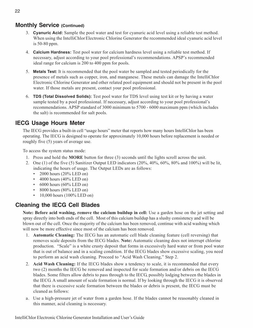
IECG Usage Hours MeterThe IECG provides a built-in cell “usage hours” meter that reports how many hours IntelliChlor has beenoperating. The IECG is designed to operate for approximately 10,000 hours before replacement is needed orroughly five (5) years of average use.
To access the system status mode:
1. Press and hold the MORE button for three (3) seconds until the lights scroll across the unit.2. One (1) of the five (5) Sanitizer Output LED indicators (20%, 40%, 60%, 80% and 100%) will be lit,
indicating the hours of usage. The Output LEDs are as follows:• 2000 hours (20% LED on)• 4000 hours (40% LED on)• 6000 hours (60% LED on)• 8000 hours (80% LED on)• 10,000 hours (100% LED on)
Cleaning the IECG Cell BladesNote: Before acid washing, remove the calcium buildup in cell: Use a garden hose on the jet setting andspray directly into both ends of the cell. Most of this calcium buildup has a slushy consistency and will beblown out of the cell. Once the majority of the calcium has been removed, continue with acid washing whichwill now be more effective since most of the calcium has been removed.
1. Automatic Cleaning: The IECG has an automatic cell blade cleaning feature (cell reversing) thatremoves scale deposits from the IECG blades. Note: Automatic cleaning does not interrupt chlorineproduction. “Scale” is a white crusty deposit that forms in excessively hard water or from pool waterthat is out of balance and in a scaling condition. If the IECG blades show excessive scaling, you needto perform an acid wash cleaning. Proceed to “Acid Wash Cleaning,” Step 2.
2. Acid Wash Cleaning: If the IECG blades show a tendency to scale, it is recommended that everytwo (2) months the IECG be removed and inspected for scale formation and/or debris on the IECGblades. Some filters allow debris to pass through to the IECG, possibly lodging between the blades inthe IECG. A small amount of scale formation is normal. If by looking through the IECG it is observedthat there is excessive scale formation between the blades or debris is present, the IECG must becleaned as follows:
a. Use a high-pressure jet of water from a garden hose. If the blades cannot be reasonably cleaned inthis manner, acid cleaning is necessary.

23
IntelliChlor Electronic Chlorine Generator Installation and User’s Guide
WARNING
Working with muriatic acid can be dangerous.When cleaning the IECG always wear rubbergloves and eye protection. Always add acid towater, do not add water to acid. Always work in awell-ventilated area. Splashing or spilling acidcan cause severe personal injury and/orproperty damage.
d. Screw the cap with washer and o-ring onto the threaded end of the IntelliChlor cell (the cap, o-ringand washer are provided with the cleaning kit). Place the ICEG vertically in a five (5) gallonbucket. Pour the acid solution (as described in step c) into the IECG until the cell blades and salinityprobes are just covered. Allow the acid solution to bubble, and to clean the blades. Note: The acidshould only be contained inside the IECG covering the blades. Try not to spill the acid on theoutside of the IECG. If acid does spill on the outside of the IECG, wash it off with water. Afoaming action will begin, which is caused by scale (calcium carbonate) being dissolved from theblades. If rigorous foaming action does not begin, the blades do not need to be cleaned (STOP THECLEANING PROCESS - go on to step “e). Otherwise, allow the blades to remainimmersed in the solution until the foaming has stopped. However, do not leave acid in theIECG for more than thirty (30) minutes. Excessive acid washing will damage the blades.
e. Remove the IECG from the bucket and place in an empty five (5) gallon bucket. Rinse the inside andoutside of the IECG thoroughly with clean tap water and inspect. If deposits are still visible, repeatthe acid cleaning process.
f. Rinse the IECG again with clean tap water and inspect. Once clean, replace the IECG and resumenormal operation.
g. If the acid wash procedure is necessary, it is recommended that a sample of pool water be analyzedby a pool professional for excessive calcium hardness (i.e. ideal range is 200 to 400 ppm) and/orimproper water balance.
h. Inspect the inside of the IECG every two (2) months (or more frequent in hard waterareas). If no scale or debris deposits are observed inside the IECG after four (4) months, it is notnecessary to continue inspections every two (2) months. However, due to possible changes in poolwater chemistry and filtering effectiveness, it is recommended that the cell be removed for inspectionat least twice a year.
i. Reconnect the IECG communication cable plug in the Power Center, then reconnect AC power to theIntelliChlor Power Center.
WinterizingVery little chlorine production is needed in cold water so long as free chlorine levels are maintained at 2.0 - 4.0ppm. The IntelliChlor Electronic Chlorine Generator will not produce chlorine below 52° F ±3° F (11° C,±1.67° C). This low-temperature cutoff extends the life of the cell. If preventative measures are not taken,freezing water may cause severe damage to the cell. Prevent freeze damage to the cell by running the poolpump continuously or winterize the pool by draining water from pump, filter, and all intake and return lines.Remove the cell, clean and store it.
Cleaning the IECG Blades (Continued)
b. To acid clean the IECG blades: Disconnect the AC power from the Power Center. Disconnect theIntelliChlor Electronic Chlorine Generator cell communication cable from the Power Center.
c. Mix one (1) quart of muriatic acid with one (1) gallon of tap water in a plastic bucket.
Note: The IntelliChlor acid cleaning kit(P/N 520670) provides a cap for the IECG toallow diluted acid solution to be poured intothe IECG to immerse the blades for cleaning.

24
IntelliChlor Electronic Chlorine Generator Installation and User’s Guide
Blank Page

25
IntelliChlor Electronic Chlorine Generator Installation and User’s Guide
Section 5Installation
This section describes how to install the IntelliChlor Electronic Chlorine Generator into the pool plumbingsystem. Also, included are connection instructions for IntelliTouch, EasyTouch and SunTouch systems. Beforeinstalling, review the IntelliChlor kit contents and required tools.
Note: For Power Center installation instructions, see the “IntelliChlor Power Center InstallationGuide” (P/N 520590).
Note: Salt is not provided. For details about the type of salt to use, see “What Type of Salt to Use,”on page 11.
Kit Contents
- One IntelliChlor Electronic Chlorine Generator- Two (2) cell union with two (2) o-rings
- User’s Guide (this manual)
Required Tools
- Tape measure- Phillips and flathead screwdriver- Pliers- Hacksaw- An NSF® approved all purpose PVC/CPVC/ABS cleaner primer- An NSF® approved all purpose PVC/CPVC/ABS cement
WARNING! When using electrical products, basic precautions should always befollowed, including the following:
• DANGER: RISK OF ELECTRIC SHOCK, WHICH CAN RESULT IN SERIOUS INJURY OR DEATH.Before attempting installation of service, ensure that all power to the circuit supplying power to thesystem is disconnected/turned off at the circuit breaker. It is recommended, but not mandatory that theIntelliChlor Power Center be connected to a circuit protected by a ground fault circuit-interrupter (GFCI).
• Grounding (earth bonding) is required. The unit should be installed by a qualified service person andgrounded.
• Install to allow access to cell buttons and power center.
• Read Safety Precautions and Important Instructions (page ii and iii). Before attempting anyelectrical wiring, be sure to read and follow Safety Instructions. Wiring should only beperformed by a qualified professional.
• Install the IntelliChlor unit a minimum of three (3) feet away from the heater outlet.
• Pipe couplings: Schedule 80, maximum pressure 75 psi at 70° F (21° C).• Note: Operate unit with minimum flow of 25 gpm. For high flow applications, use a bypass loop (see
page 4) for best flow sensing.• Note: Provide at least 12"-18" of straight pipe in front of the cell inlet.

26
IntelliChlor Electronic Chlorine Generator Installation and User’s Guide
IntelliChlor “Dummy” Cell
After new pool construction has been completed, in order to prevent debris from entering the IntelliChlorElectronic Chlorine Generator, it is recommended that the IntelliChlor Electronic Chlorine Generator“dummy” cell (P/N 520588) be installed before installing the IntelliChlor Electronic Chlorine Generator.After the pool system has flushed the debris from the pipes, remove the “dummy cell” and install theIntelliChlor Electronic Chlorine Generator.
Installing the IntelliChlor Cell Assembly
Install the IntelliChlor cell assembly no closer than three (3) feet away from the heater outlet, if used. Formore information see plumbing diagrams on page 4 and 5.
Note: For best flow sensing, provide at least 12"-18" of straight pipe in front of the cell inlet.
Note: After new pool construction has been completed, in order to prevent debris from entering theIntelliChlor cell assembly, it is recommended that the IntelliChlor pass-through cell (P/N 520588) beinstalled before installing the IntelliChlor cell. After the pool system has flushed the debris from thepipes, remove the pass-through cell and install the IntelliChlor cell.
Note: Pipe couplings: Schedule 80, maximum pressure 75 psi at 70° F (21° C)
Coupling
Coupling
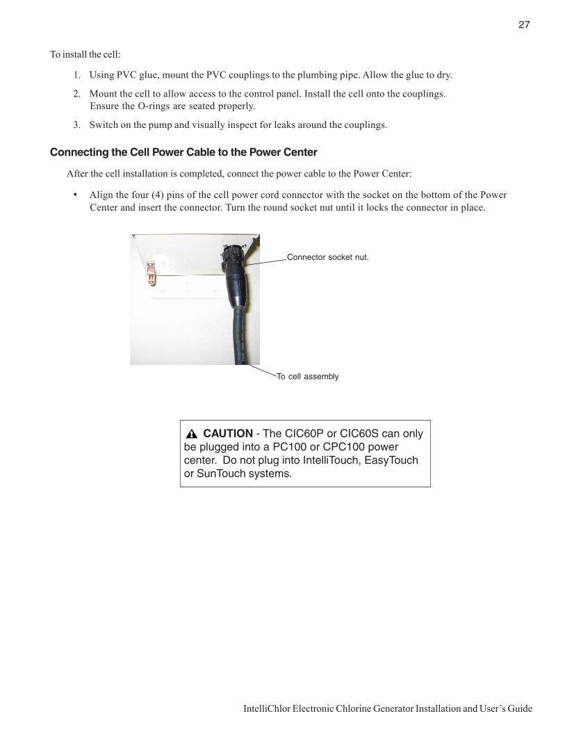
27
IntelliChlor Electronic Chlorine Generator Installation and User’s Guide
To install the cell:
1. Using PVC glue, mount the PVC couplings to the plumbing pipe. Allow the glue to dry.
2. Mount the cell to allow access to the control panel. Install the cell onto the couplings.Ensure the O-rings are seated properly.
3. Switch on the pump and visually inspect for leaks around the couplings.
Connecting the Cell Power Cable to the Power Center
After the cell installation is completed, connect the power cable to the Power Center:
• Align the four (4) pins of the cell power cord connector with the socket on the bottom of the PowerCenter and insert the connector. Turn the round socket nut until it locks the connector in place.
Connector socket nut.
To cell assembly
CAUTION - The CIC60P or CIC60S can onlybe plugged into a PC100 or CPC100 powercenter. Do not plug into IntelliTouch, EasyTouchor SunTouch systems.

28
IntelliChlor Electronic Chlorine Generator Installation and User’s Guide
Blank Page

29
IntelliChlor Electronic Chlorine Generator Installation and User’s Guide
Section 6Troubleshooting
Use the following troubleshooting information to resolve possible problems with the IntelliChlor ElectronicChlorine Generator.
Note: Switch power off to unit before to attempting service or repair. Always remove AC power to PowerCenter when plugging or unplugging the IntelliChlor cell into the Power Center.
Table 1: Troubleshooting
melborP esuaCelbissoP noitcAevitcerroC
.enirolhconrowoL loopnilevel)dicacirunayc(rezilibatswoL.)ylnoslooproodtuo(retaw
otylnoslooproodtuonidicacirunaycddAs'lanoisseforplooprepMPP05-03niatniamelbaT,trahCrezilibatSeeS.snoitadnemmocer
.41egap,2
.GCEIehtfosruohgnitarepotneiciffusnI eeS.yadrepemitgnitarepoGCEIehtesaercnI.noitamrofniemitnurpmuprof51egap
woloottesegatnecrepTUPTUOREZITINAS.%0tafforo
ehtgnisserpybTUPTUOREZITINASesaercnI.8egapeeS.nottubEROM
erutarepmetrehtaewnisesaercnitneceR.tuptuOrezitinaSGCEIehtgnisaercnituohtiw
ehtgnisserpybTUPTUOREZITINASesaercnI.8egapeeS.nottubEROM
yvaehoteudenirolhcfossolyraropmeTyvaehrorezilitref,sevael,niar,daolcinagro.loopgnisustepro,ytraptnecer,daolrehtab
42rofnurotwolladnaedom"tsooB"teS-repus,wolootllitsfI,kcehceR.sruoh
ekaT(.ecruosedistuonagnisuybetanirolhc.)lanoisseforploopotelpmasretawloop
loopnileveltlas)mpp0062nahtssel(woL.noitcudorpenirolhcffostuhs,retaw
leveLtlaS"eeS.sthgilyalpsiDtlaSevresbO.7egap",sDELsutatS
.leveletahpsohpdnaetartinhgiH .lanoisseforPlooPtcatnoC
.retawloopnitneserpslateM .lanoisseforPlooPtcatnoC
nopuylreporpdekcohstonro,retawloopweN.putrats
.looPetanirolhCrepuS,")noitanirolhCrepuS(erudecorPpu-tratS"eeS
.61egap
.llecytridrodeggolC .yrassecenfinaelC.noitcepsnirofllecevomeR.)02egapees(

30
IntelliChlor Electronic Chlorine Generator Installation and User’s Guide
Table 1: Troubleshooting (Continued)
melborP esuaCelbissoP noitcAevitcerroC
siDELtlasWOLdeR.no
gniebsienirolhcoN.tlassdeenretawlooP.decudorp
.41,31segapnodebircsedsatlasddA
nothgilTLASWOLdeRthgilLLECneergdna
gnihsalf
deenyamdnawolsiretawloopnileveltlaS.gnitcepsni
DOOGotyrassecenfidda,leveltlaskcehCfI.retawniximottlasrofsruoh42wollA.level
,sruoh42retfagnihsalfllitssithgilLLEC.yrassecenfinaelcdnallectcepsnidnaevomer
thgilTLASKCEHCdeRnosi
.loopnitlashguonetoN.llafniaRyvaeH
.loopnikaeL
.mpp0043eveihcaotloopottlasddA.41,31egapeeS
thgiltlasDOOGneerGgnihsalfsi
otegamadesuacyaM.loopnitlashcumooTgnidnuorrusdnatnempiuqedetaelerloop
.secafrus
neht,retawemosgniniardybretawloopetuliDretawhserfhtiwgnillif
sithgilRETAWDLOC.der
.F°25wolebsiretaW otF°25evobaebtsumerutarepmetretawehT.enirolhcecudorp
tonseodthgilLLEC.noemoc
.%00ottesnoitcudorPenirolhC derisedotNOITCUDORPENIROLHCtsujdA.egatnecrep
htiwdeggulpsilleC.wolfretawtneiciffusnI.emirptsolsahpmup,sirbed
eeS.llecnaelcro/dnanoitcurtsboevomeR.yrassecenfipmupemirP.01egap
.mpp0062wolebleveltlaS ,41,31segapnodebircsedsatlasddA.51dna
gnihsalfsithgilLLEC.neerg
leveltlaskcehC
seriuqerdnapu-dliubmuiclacsahlleC.gninaelc
.ecnalabdnayrtsimehcretawkcehC.mpp0ebdluohstnetnoclatemETON
mpp0043niatniamotyrassecenfitlasddA.muminim
dicaroferudecorPecnanetniaMotrefeR",ecnanetniaMresU"eeS.gninaelc/hsaw
.9egapno
lacimehcgnisuretawmorfslatemevomeR.noitulos
.dersithgilwolF .wolfretawtneiciffusedivorpotsliafpmuP ,.e.i,pmupehtfonoitarepotcerrocrofkcehCreniartsdeggolcroemirppmupfossol
.steksab
.sevlavdesolC .stnemngilaevlavllatcerrocdnakcehC
.retlifytriD .serudecorpgninaelcretlifwolloF
.llecrotanirolhCehtninoitcurtsbO gninaelcwolloF.noitcepsnirofllecevomeR",gninaelClleCcitylortcelE"eeS.serudecorp
.01egapno
seodtinurolhCilletnI.rewopevahton
.neposiretneCrewoPniesuF rewoPfomottobtadetacol,esufCAecalpeR.retneC
.retneCrewoPotrewopCAoN 022roCAV011gnidivorpsikcolcemityfireV.evitcanehwretneCrewoPotCAV
rewoPniyltcerrocderiwtonsdaelremrofsnarT.retneC
ybecruosCAotderiwsdaelremrofsnartyfireVfoedisninolacedmargaidgniriwotgnirrefer
.revocretneCrewoP

31
IntelliChlor Electronic Chlorine Generator Installation and User’s Guide
System Specifications - 110 VAC and 230 VAC Wiring
Circuit Protection: Two-pole 20 AMP device at the electrical panel.
IntelliChlor Model CIC60P and CIC60S
Input: 95-130 VAC, 50/60 Hz, 220 Watts (2 AMP) or 220-240 VAC, 50/60 Hz, 220 Watts (1 AMP).
Output: 22-39 VDC @ 7.5 AMPS maximum from the Power Center.
Water flow: 25 gallons per minute minimum. 105 gallons per minute maximum. Maximum pressure: 75 psi
115 VAC Basic System Wiring with Pool Pump Timer and ORP
IMPORTANT: When using IntelliChlor with an IntelliTouch system, it is recommended to wire
the Power Center to the pump side of the relay located in the IntelliTouch Load Center. This
method does not require a ground fault circuit-interrupter (GFCI) to protect the circuit.
IntelliChlor (SCG) AC Wiring Instructions: When using the IntelliChlor saltchlorine generator and an IntelliFlo pump (or 2-speed pump) with a PentairWater Pool and Spa® IntelliTouch®, EasyTouch® or SunTouch® automationcontrol system , the IntelliChlor AC power center wires must be connected tothe PUMP SIDE OF THE MAIN FILTER PUMP RELAY located in the load/powercenter (see page 29 for diagram). This ensures that the IntelliChlor cellproduces chlorine only when the main filter pump is on. This method does notrequire a ground fault circuit-interrupter (GFCI) to protect the circuit. Note: Fornon-automation systems using a time clock, see diagram below.

32
IntelliChlor Electronic Chlorine Generator Installation and User’s Guide
220 VAC Basic System Wiring with Pool Pump Timer

33
IntelliChlor Electronic Chlorine Generator Installation and User’s Guide
LIMITED WARRANTY
Pentair Water Pool and Spa, Inc. ("Pentair") warrants the IntelliChlor® Electronic Chlorine Generator (IECG) as follows:
IECG Cell Limited Warranty: Pentair warrants the IECG to be free from defects in material and/or workmanship for aperiod of one (1) year from the original date of installation.
IECG Power Center/Power Supply Limited Warranty: Pentair warrants the IECG Power Center to be free from defects inmaterial and/or workmanship for a period of one (1) year (parts only) from the original date of installation.
Exceptions that shall result in Pentair’s denial of a warranty claim:
1. Damage caused by careless handling, improper repackaging, or shipping.
2. Damage due to misapplication, misuse, abuse or failure to operate equipment as specified in the IECGInstallation and User’s Guide.
3. Damage caused by failure to install products as specified in the IECG Installation and User’s Guide.
4. Damage due to unauthorized product modifications or alterations, or failure to use Pentair original replacementparts.
5. Damage caused by negligence, or failure to properly maintain products as specified in the IECG Installation andUser’s Guide.
6. Damage caused by failure to maintain water chemistry in conformity with the standards set forth in the IECGInstallation and User’s Guide.
7. Damage caused by water scaling, freezing or any conditions causing inadequate water circulation.
8. Accidental damage, fire, acts of God, or other circumstances outside the control of Pentair.
• This warranty extends to the original retail owner (Customer) only, beginning on the date of installation and isnot enforceable by any other party. Proof of purchase and/or date of installation will be required for all warrantyclaims. Customer agrees to pay all shipping charges to Pentair.
• Warranties by others: Some products incorporate components manufactured by other manufacturers. Some ofthese provide warranties in addition to the warranty provided herein. In all such cases a copy of that warrantywill be provided with the product. To the extent protection provided under any such third party warrantyexceeds the Limited Warranty provided herein, the Customer must look only to that other manufacturer for theadditional warranty protection.
Warranty Obligations of Pentair Water: Should a defect in workmanship and/or material in any item covered by thiswarranty become evident during the term of the warranty, then upon the Customer following the procedures set forthbelow, Pentair will, at its option, repair or replace such item or part at its own cost and expense. Pentair’s maximumobligation under this warranty is limited to the repair and replacement of the IECG. Pentair disclaims all other expressed orimplied warranty obligations.
Pentair is not, however, responsible under this warranty for any cost of shipping or transportation of the equipment orparts thereof to or from Pentair’s Technical Service Department. Also, Pentair is not liable for any loss of time,inconvenience, incidental expenses such as telephone calls, labor or material charges incurred in connection with theremoval or replacement of the equipment, or any other incidental or consequential damages, including but not limited todamage to pool equipment or any surface in or around the pool in which the IECG is installed.
PLEASE NOTE: Some states do not allow the exclusion or limitation of incidental, or consequential damages, so the abovelimitation or exclusion may not apply to you.
No Other Warranties: TO THE MAXIMUM EXTENT PERMITTED BY APPLICABLE LAW, PENTAIR DISCLAIMS ALLOTHER WARRANTIES, WHETHER EXPRESS OR IMPLIED, INCLUDING, BUT NOT LIMITED TO THE IMPLIEDWARRANTIES OF MERCHANTABILITY AND FITNESS FOR A PARTICULAR PURPOSE.
Continued on next page.

34
IntelliChlor Electronic Chlorine Generator Installation and User’s Guide
P/N 521011 - Rev C
*521011*
WARNING: Salt is an inherently corrosive material. While the levels of salt required for proper operationof the IntelliChlor Electronic Chlorine Generator are relatively low when compared to sea water and other saltsolutions, placing any amount of salt in your pool increases the likelihood of corrosion or other deterioration ofpool equipment and any surfaces used in and around your pool. Metal parts (including steel pools) and certainnatural and man-made surfaces are particularly susceptible to corrosion and deterioration when used in andaround salt water pools. Pentair Water Pool and Spa (“Pentair”) does not represent or otherwise guarantee thatthe proper use of the IntelliChlor Electronic Chlorine Generator will prevent corrosion or other deterioration ofpool equipment and any surfaces used in and around your pool. Consult your experienced pool professional,who should be able to advise you on the proper material selection, installation techniques for those materials,and the proper use, care and maintenance of those materials for your specific pool type and location in order tominimize the corrosion and deterioration that is inherent in and around salt water pools.
Procedure for Obtaining Performance: In order to obtain the benefits of this warranty, the Customer who made theoriginal retail purchase must contact the Pentair Technical Service Department upon discovery of the defect, but in noevent later than the expiration date of the warranty period provided in this warranty. Upon receipt of this communication,Pentair will promptly notify the Customer of the address to which the defective item may be shipped. The Customer shallthen ship the item, freight prepaid, to the address indicated, together with a "RETURN GOODS AUTHORIZATION" formobtained from Pentair’s Technical Service and a brief description of the problems encountered. Unauthorized returns willnot be accepted. Freight must be prepaid by customer.
Warranties or Representations by Others: No dealer or other third party entity has any authority to make any warrantiesor representations concerning Pentair or its products. Accordingly, Pentair is not responsible for any such warranties orrepresentations.
Other Rights: This warranty gives you specific legal rights and you may also have other rights, which vary from state tostate. This warranty supersedes all previous publications.
PENTAIR WATER POOL AND SPA, INC.1620 Hawkins Ave. Sanford, NC 27330 - 10951 W. Los Angeles Ave. Moorpark, CA 93021 - Phone 800-831-7133 - Fax 800-284-4151
LIMITED WARRANTY (Continued)