Chlorine Dioxide Generator LOTUS MINI - emec.com.au · The chlorine dioxide generator is used for...
72
Chlorine Dioxide Generator LOTUS MINI Operation Manual Read this manual completely before you start LOTUS. Do not trash this manual and store it nearby the generator for later use. This manual contains important information about the installation and operation safety. Take care about the following instructions to avoid personal injuries and material damages! The operator is responsible in case of damages caused by installation and operation failures! English R4-11-14 DOWNLOAD ERMES COMMUNICATION SOFTWARE www.ermes-server.com Chlorine dioxide, like all oxidizing agents, could produce corrosion phenomena of the plant. It is advisable to perform cadenced checks and to treat the plant with specific chemical products. It is also advisable to use chlorine dioxide resistant materials at the point of injection of the product.
Transcript of Chlorine Dioxide Generator LOTUS MINI - emec.com.au · The chlorine dioxide generator is used for...

Chlorine Dioxide Generator LOTUS MINI
Operation Manual Read this manual completely before you start LOTUS. Do not trash this manual and store it nearby the generator for later use.
This manual contains important information about the installation and operation safety. Take care about the following instructions to avoid personal injuries and material damages! The operator is responsible in case of damages caused by installation and operation failures!
English
R4-11-14
DOWNLOAD ERMES COMMUNICATION SOFTWAREwww.ermes-server.com
Chlorine dioxide, like all oxidizing agents, could produce corrosion phenomena of the plant. It is advisable to perform cadenced checks and to treat the plant with specific chemical products. It is also advisable to use chlorine dioxide resistant materials at the point of injection of the product.
2
NORME CEEC RULES(STANDARD EC)NORMAS DE LA CE
Direttiva Bassa Tensione Low Voltage Directive Directiva de baja tensión
Direttiva EMC Compatibilità ElettromagneticaEMC electromagnetic compatibility directiveEMC directiva de compatibilidad electromagnética
2014/35/UE
2014/30/UE
⎬
⎬
Danger!
GENERAL SAFETY GUIDELINES
In emergencies the instrument should be switched off immediately! Disconnect the power cable from the power supply!
When installing always observe local regulations!
Manufacturer is not liable for any unauthorized use or misuse of this product that may cause injury,
damage to persons and / or materials.
Caution! Instrument must be accessible at all times for both operating and servicing. Access must not be obstructed in any way!
Feeder should be interlocked with a no-flow protection device to automatically shut-off the pumps when there is no flow!
Pumps and accessories must be serviced and repaired by qualified and authorized personnel only!
Always discharge the liquid end before servicing the instrument!
Empty and rinse the liquid end before work on a pump which has been used with hazardous or unknown chemicals!
Always read chemical safety datasheet!
Always wear protective clothing when handling hazardous or unknown chemicals!
Instrument must be operated / serviced by trained technicians only!
All connection operations must be performed while the instrument is not connected to main supply!
3
Directory 1. General Safety Guidelines 4 1.1 Symbols 4 1.2 Safety instructions 4 1.3 CE-Conformity 5
2. General Description 6
3. Construction 7 3.1 Construction overview 7 3.2 Description and details 7
4. „LOTUS“ - Controller 8 4.1 Start display 8 4.2 Main display 8 4.3 Control element „Click-Wheel“ 8 4.4 Status displays 9 4.5 Logbook 10 4.6 Help 10
5. Adjustment of production capacity 11 5.1 Proportional mode 12 5.2 Constant mode 13 5.3 Analog mode 13 5.4 Batch mode 14
6. Replacement of chemical cans and pump priming 15
7. LOTUS Terminal board 16
8. Technical Data 17
9. 18 Failure Messages
Communication 21
NOTE:
WHEN CHANGING WORKING MODE, SETPOINT PARAMETERS SHOULD BE ENTERED AGAIN.
4
1. General Safety Guidelines
1.1 General remarks This manual includes basic directions for the assembling, operation and maintenance. Therefore it is obligatory for the assembly technician as well as for the operator to study the complete manual before starting with the installation and start-up. This manual must be present at the generator at any time. It is also obligatory for the operator to consider the general directions in chapter “Safety instructions” as well as the specific safety instructions included in the other chapters of this manual.
Notice: • For some of the following described functions additional accessories (not included in the delivery
scope of LOTUS) may be required.• Depending to the software release of the LOTUS-controller some of the described features may
not be available. Or some functions are available, but not described in this manual. Please contactyour dealer in case of the requirement for more information.
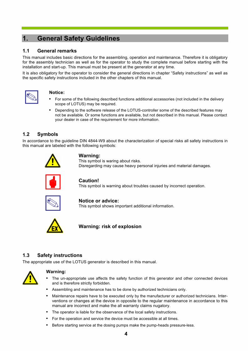
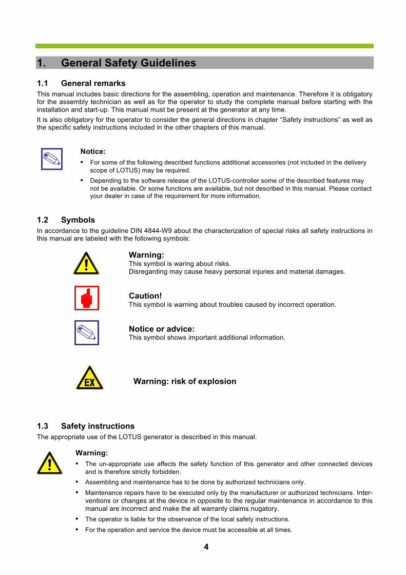
1.2 Symbols In accordance to the guideline DIN 4844-W9 about the characterization of special risks all safety instructions in this manual are labeled with the following symbols:
Warning: This symbol is waring about risks. Disregarding may cause heavy personal injuries and material damages.
Caution! This symbol is warning about troubles caused by incorrect operation.
Notice or advice: This symbol shows important additional information.
1.3 Safety instructions The appropriate use of the LOTUS generator is described in this manual.
Warning: • The un-appropriate use affects the safety function of this generator and other connected devices
and is therefore strictly forbidden.• Assembling and maintenance has to be done by authorized technicians only.
• Maintenance repairs have to be executed only by the manufacturer or authorized technicians. Inter-ventions or changes at the device in opposite to the regular maintenance in accordance to thismanual are incorrect and make the all warranty claims nugatory.
• The operator is liable for the observance of the local safety instructions.
• For the operation and service the device must be accessible at all times.
• Before starting service at the dosing pumps make the pump-heads pressure-less.
Warning: risk of explosion
• Drain and flush the pump-heads with clean water before starting the service.
• Take attention to the chemical safety data sheets!
• Wear protection clothes for the handling with unknown and hazardous chemicals.
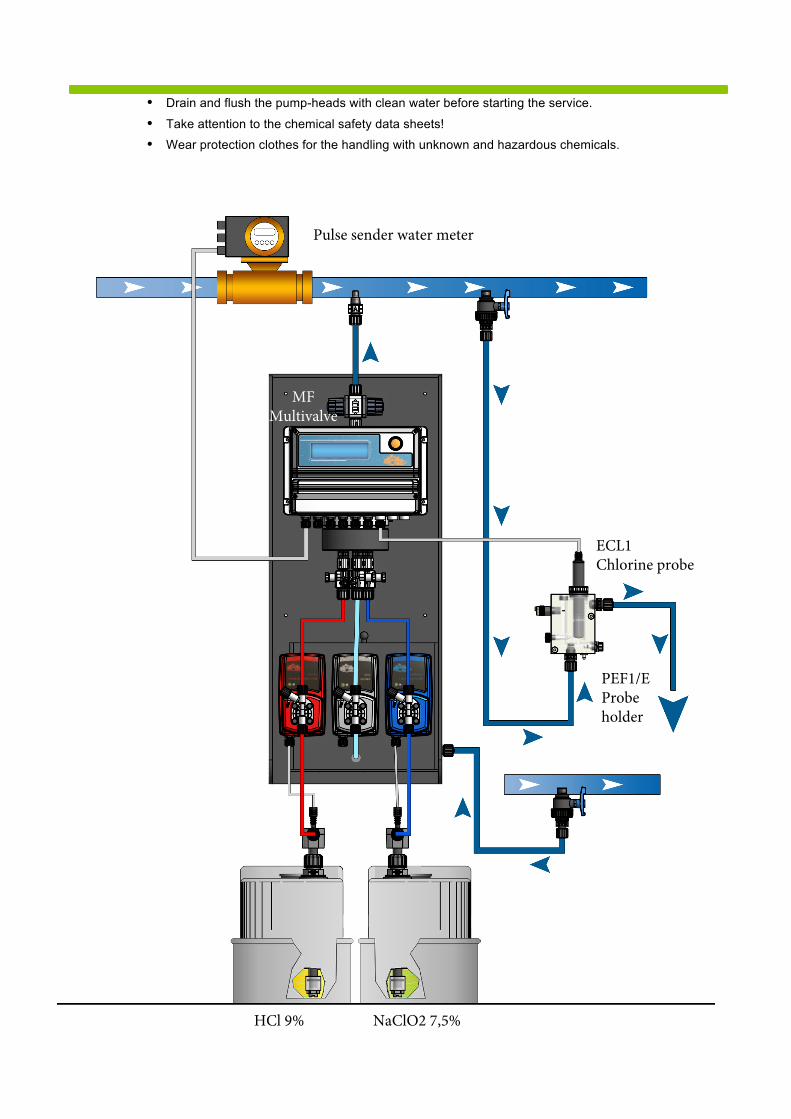
HCl 9% NaClO2 7,5%
PEF1/EProbe holder
ECL1 Chlorine probe
MF Multivalve
Pulse sender water meter

6
Directions for the operator (Specific information for applicable regulations in Germany): • Accident prevention regulation (UVV) „Chlorination of water“, GUV V-D5 E.• „Dosing plants for chlorine dioxide“, DVGW guideline W 624 (latest version respectively).• „Chlorine dioxide in water treatment“, DVGW worksheet W 224 (latest version respectively).• Guidelines for the protection of groundwater against polution.
(§ 19 Federal Water Act – WHG dated 23.9.1986).• Ordinance of hazardous substances (GefStoffV) – especially § 17 (obligatory protection)
and § 20 (operation instruction).
1.4 CE - Conformity
The LOTUS generator is corresponding to the following EU-standards:
The following standards are considered: • Machinery directive 89/392/EWG IIA inclusive all actual changes within the year of
Manufacturing 91/368/EWG – Mod. 1, and 93/44/EWG – Mod. 2.• Guideline 2004/108 EG about the electromagnetic tolerance of electric equipment.• Low-voltage directive 2006/95/EG.• EC – Pressure Equipment Directive (97/23/EG)
The following harmonized safety guidelines are considered: • UNI EN 292/1 – Safety of machines• UNI EN 292/2 – Safety of machines; technical principles.• CEI EN 60204-1-98 – General requirements for electric equipment in machines.
Notice: A declaration of conformity can be ordered from the manufacturer.
7
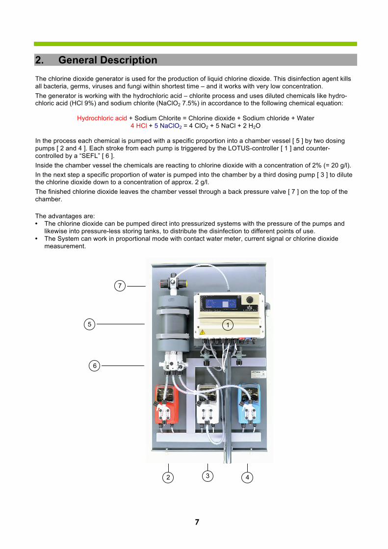
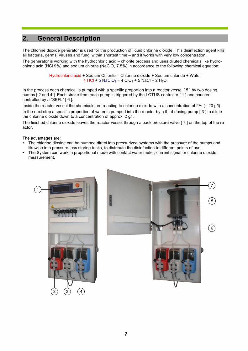
2. General DescriptionThe chlorine dioxide generator is used for the production of liquid chlorine dioxide. This disinfection agent kills all bacteria, germs, viruses and fungi within shortest time – and it works with very low concentration. The generator is working with the hydrochloric acid – chlorite process and uses diluted chemicals like hydro-chloric acid (HCl 9%) and sodium chlorite (NaClO2 7.5%) in accordance to the following chemical equation:
Hydrochloric acid + Sodium Chlorite = Chlorine dioxide + Sodium chloride + Water 4 HCl + 5 NaClO2 = 4 ClO2 + 5 NaCl + 2 H2O
In the process each chemical is pumped with a specific proportion into a chamber vessel [ 5 ] by two dosing pumps [ 2 and 4 ]. Each stroke from each pump is triggered by the LOTUS-controller [ 1 ] and counter-controlled by a “SEFL” [ 6 ]. Inside the chamber vessel the chemicals are reacting to chlorine dioxide with a concentration of 2% (= 20 g/l). In the next step a specific proportion of water is pumped into the chamber by a third dosing pump [ 3 ] to dilute the chlorine dioxide down to a concentration of approx. 2 g/l. The finished chlorine dioxide leaves the chamber vessel through a back pressure valve [ 7 ] on the top of the chamber.
The advantages are: • The chlorine dioxide can be pumped direct into pressurized systems with the pressure of the pumps and
likewise into pressure-less storing tanks, to distribute the disinfection to different points of use.• The System can work in proportional mode with contact water meter, current signal or chlorine dioxide
measurement.
2 3 4
1 5
6
7
8
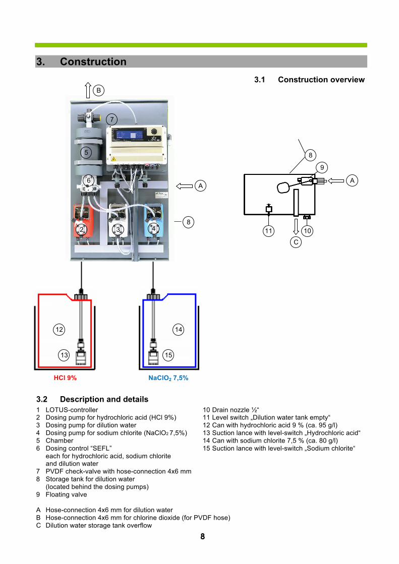
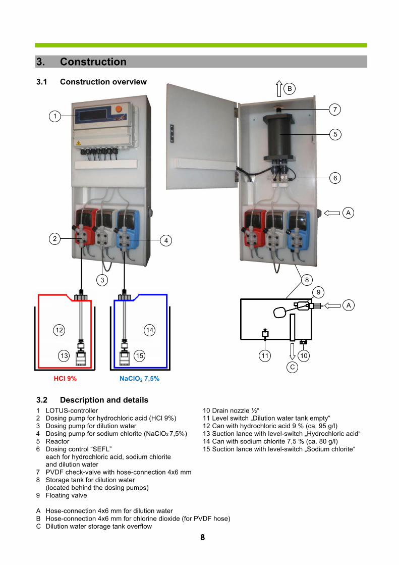
3. Construction3.1 Construction overview
3.2 Description and details 1 LOTUS-controller 10 Drain nozzle ½“ 2 Dosing pump for hydrochloric acid (HCl 9%) 11 Level switch „Dilution water tank empty“ 3 Dosing pump for dilution water 12 Can with hydrochloric acid 9 % (ca. 95 g/l) 4 Dosing pump for sodium chlorite (NaClO2 7,5%) 13 Suction lance with level-switch „Hydrochloric acid“ 5 Chamber 14 Can with sodium chlorite 7,5 % (ca. 80 g/l) 6 Dosing control “SEFL” 15 Suction lance with level-switch „Sodium chlorite“
each for hydrochloric acid, sodium chlorite and dilution water 7 PVDF check-valve with hose-connection 4x6 mm 8 Storage tank for dilution water
(located behind the dosing pumps) 9 Floating valve
A Hose-connection 4x6 mm for dilution water B Hose-connection 4x6 mm for chlorine dioxide (for PVDF hose) C Dilution water storage tank overflow
4
HCl 9% NaClO2 7,5%
8
10
9
11
C
12
13
14
15
A A
3 2
5
7
B
6
8 4
9
4. „LOTUS“ Controller
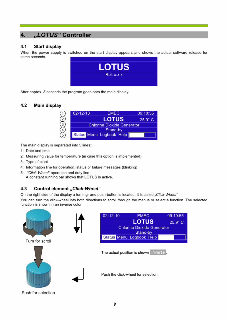
4.1 Start display When the power supply is switched on the start display appears and shows the actual software release for some seconds.
After approx. 3 seconds the program goes onto the main display.
4.2 Main display
The main display is separated into 5 lines:: 1: Date and time 2: Measuring value for temperature (in case this option is implemented) 3: Type of plant 4: Information line for operation, status or failure messages (blinking) 5: “Click-Wheel” operation and duty line.
A constant running bar shows that LOTUS is active.
4.3 Control element „Click-Wheel“ On the right side of the display a turning- and push-button is located. It is called „Click-Wheel“. You can turn the click-wheel into both directions to scroll through the menus or select a function. The selected function is shown in an inverse color.
The actual position is shown .
Push the click-wheel for selection.
Inverse
LOTUSRel: x.x.x
1 2 3 4 5
02-12-10 EMEC 09:10:55 LOTUS 25.9° C
Chlorine Dioxide Generator Stand-by
Status Menu Logbook Help Status
02-12-10 EMEC 09:10:55 LOTUS 25.9° C
Chlorine Dioxide Generator Stand-by
Status Menu Logbook Help Status Turn for scroll
Push for selection
10
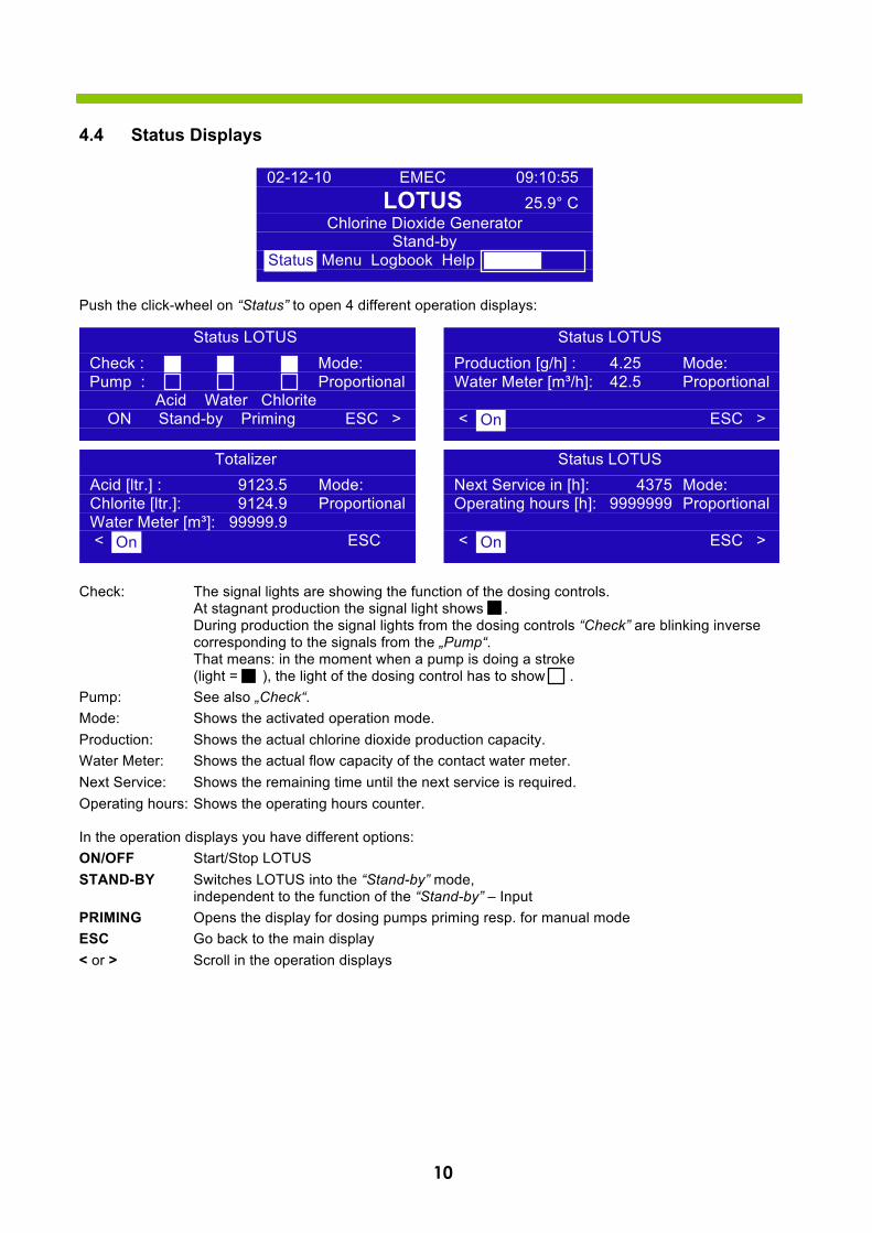
4.4 Status Displays
Push the click-wheel on “Status” to open 4 different operation displays:
Check: The signal lights are showing the function of the dosing controls. At stagnant production the signal light shows . During production the signal lights from the dosing controls “Check” are blinking inverse corresponding to the signals from the „Pump“. That means: in the moment when a pump is doing a stroke (light = ), the light of the dosing control has to show .
Pump: See also „Check“. Mode: Shows the activated operation mode. Production: Shows the actual chlorine dioxide production capacity. Water Meter: Shows the actual flow capacity of the contact water meter. Next Service: Shows the remaining time until the next service is required. Operating hours: Shows the operating hours counter.
In the operation displays you have different options: ON/OFF Start/Stop LOTUS STAND-BY Switches LOTUS into the “Stand-by” mode,
independent to the function of the “Stand-by” – Input PRIMING Opens the display for dosing pumps priming resp. for manual mode ESC Go back to the main display < or > Scroll in the operation displays
Status LOTUS Production [g/h] : 4.25 Mode: Water Meter [m³/h]: 42.5 Proportional
< ESC > On
Totalizer Acid [ltr.] : 9123.5 Mode: Chlorite [ltr.]: 9124.9 Proportional Water Meter [m³]: 99999.9 < ESC On
Status LOTUS Next Service in [h]: 4375 Mode: Operating hours [h]: 9999999 Proportional
< ESC > On
02-12-10 EMEC 09:10:55 LOTUS 25.9° C
Chlorine Dioxide Generator Stand-by
Status Menu Logbook Help Status
Status LOTUS Check : Mode: Pump : Proportional
Acid Water Chlorite ON Stand-by Priming ESC >
11
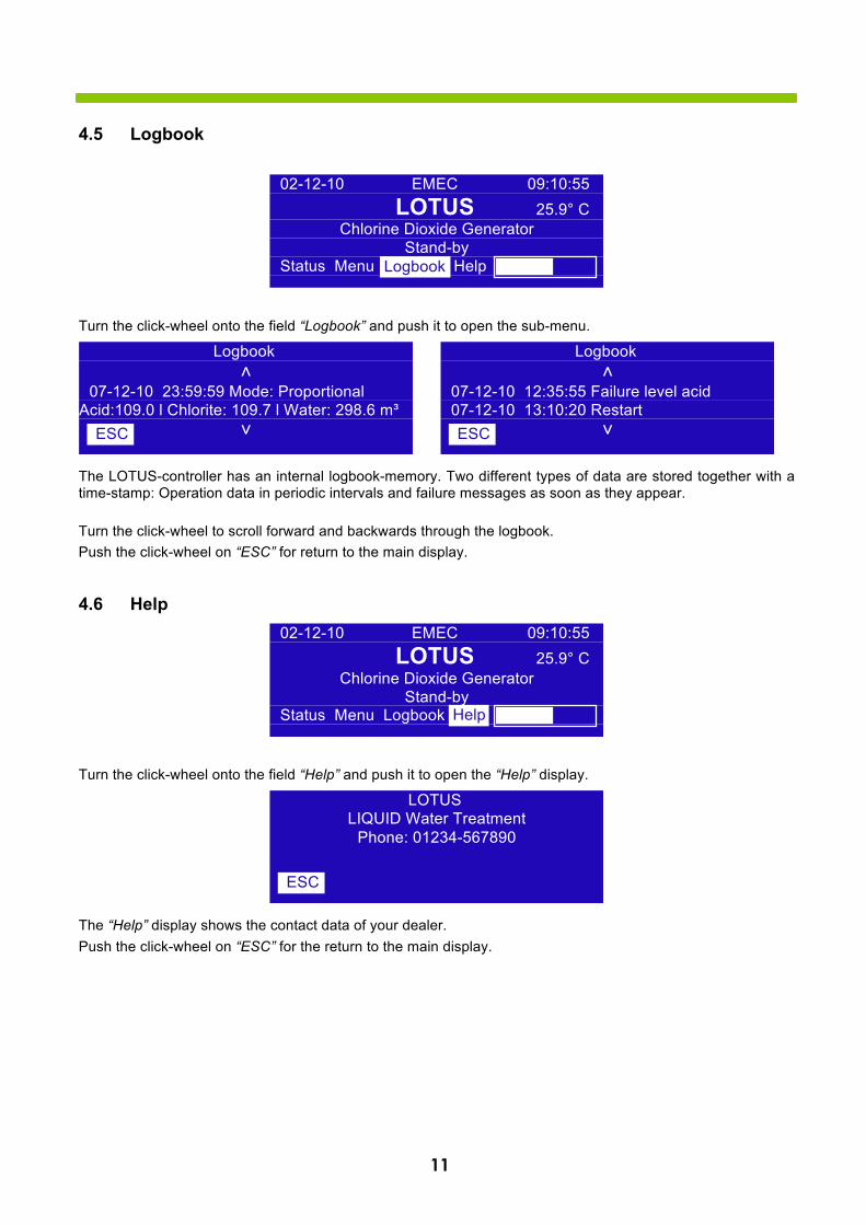
4.5 Logbook
Turn the click-wheel onto the field “Logbook” and push it to open the sub-menu.
The LOTUS-controller has an internal logbook-memory. Two different types of data are stored together with a time-stamp: Operation data in periodic intervals and failure messages as soon as they appear.
Turn the click-wheel to scroll forward and backwards through the logbook. Push the click-wheel on “ESC” for return to the main display.
4.6 Help
Turn the click-wheel onto the field “Help” and push it to open the “Help” display.
The “Help” display shows the contact data of your dealer. Push the click-wheel on “ESC” for the return to the main display.
Logbook ˄
07-12-10 23:59:59 Mode: Proportional Acid:109.0 l Chlorite: 109.7 l Water: 298.6 m³
˅ ESC
Logbook ˄
07-12-10 12:35:55 Failure level acid 07-12-10 13:10:20 Restart
˅ ESC
LOTUS LIQUID Water Treatment
Phone: 01234-567890
ESC
02-12-10 EMEC 09:10:55 LOTUS 25.9° C
Chlorine Dioxide Generator Stand-by
Status Menu Logbook Help Logbook
02-12-10 EMEC 09:10:55 LOTUS 25.9° C
Chlorine Dioxide Generator Stand-by
Status Menu Logbook Help Help
12
5. Adjustment of production capacity
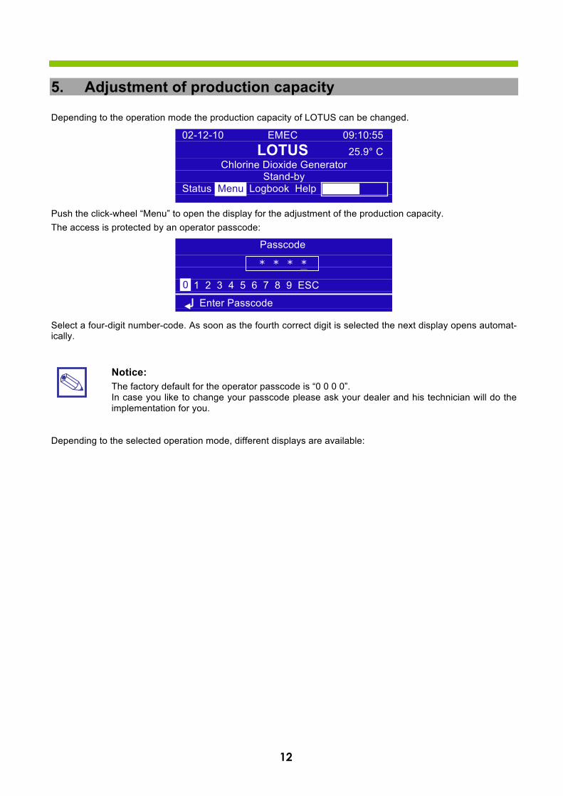
Depending to the operation mode the production capacity of LOTUS can be changed.
Push the click-wheel “Menu” to open the display for the adjustment of the production capacity. The access is protected by an operator passcode:
Select a four-digit number-code. As soon as the fourth correct digit is selected the next display opens automat-ically.
Notice: The factory default for the operator passcode is “0 0 0 0”. In case you like to change your passcode please ask your dealer and his technician will do the implementation for you.
Depending to the selected operation mode, different displays are available:
Passcode
0 1 2 3 4 5 6 7 8 9 ESC
Enter Passcode
* * * *
0
02-12-10 EMEC 09:10:55 LOTUS 25.9° C
Chlorine Dioxide Generator Stand-by
Status Menu Logbook Help Menu
13
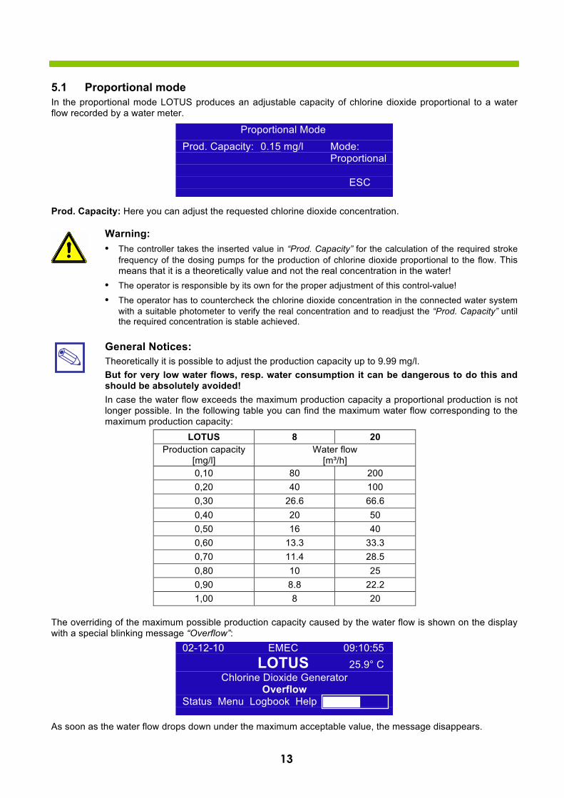
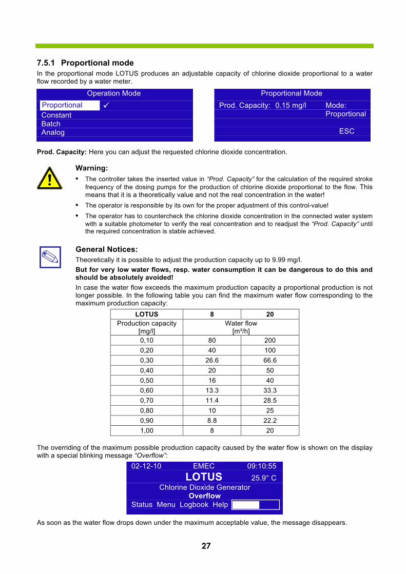
5.1 Proportional mode In the proportional mode LOTUS produces an adjustable capacity of chlorine dioxide proportional to a water flow recorded by a water meter.
Prod. Capacity: Here you can adjust the requested chlorine dioxide concentration.
Warning: • The controller takes the inserted value in “Prod. Capacity” for the calculation of the required stroke
frequency of the dosing pumps for the production of chlorine dioxide proportional to the flow. This means that it is a theoretically value and not the real concentration in the water!
• The operator is responsible by its own for the proper adjustment of this control-value!
• The operator has to countercheck the chlorine dioxide concentration in the connected water systemwith a suitable photometer to verify the real concentration and to readjust the “Prod. Capacity” untilthe required concentration is stable achieved.
General Notices: Theoretically it is possible to adjust the production capacity up to 9.99 mg/l. But for very low water flows, resp. water consumption it can be dangerous to do this and should be absolutely avoided! In case the water flow exceeds the maximum production capacity a proportional production is not longer possible. In the following table you can find the maximum water flow corresponding to the maximum production capacity:
LOTUS 8 20 Production capacity
[mg/l] Water flow
[m³/h] 0,10 80 200 0,20 40 100 0,30 26.6 66.6 0,40 20 50 0,50 16 40 0,60 13.3 33.3 0,70 11.4 28.5 0,80 10 25 0,90 8.8 22.2 1,00 8 20
The overriding of the maximum possible production capacity caused by the water flow is shown on the display with a special blinking message “Overflow”:
As soon as the water flow drops down under the maximum acceptable value, the message disappears.
Proportional Mode Prod. Capacity: 0.15 mg/l Mode:
Proportional
ESC
02-12-10 EMEC 09:10:55 LOTUS 25.9° C
Chlorine Dioxide Generator Overflow
Status Menu Logbook Help
14
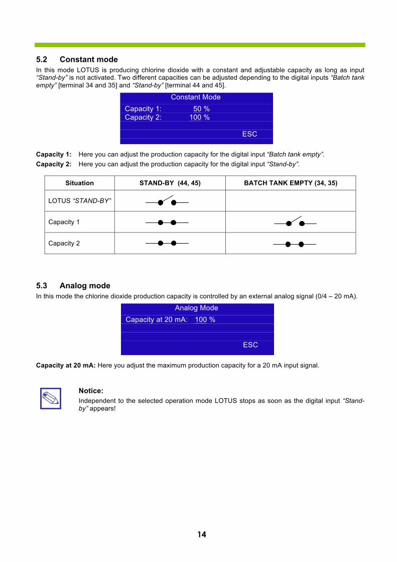
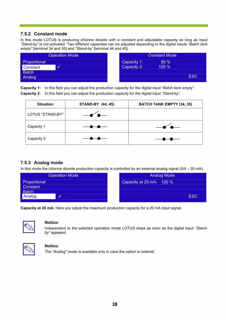
5.2 Constant mode In this mode LOTUS is producing chlorine dioxide with a constant and adjustable capacity as long as input “Stand-by” is not activated. Two different capacities can be adjusted depending to the digital inputs “Batch tank empty” [terminal 34 and 35] and “Stand-by” [terminal 44 and 45].
Capacity 1: Here you can adjust the production capacity for the digital input “Batch tank empty”. Capacity 2: Here you can adjust the production capacity for the digital input “Stand-by”.
Situation STAND-BY (44, 45) BATCH TANK EMPTY (34, 35)
LOTUS “STAND-BY”
Capacity 1
Capacity 2
5.3 Analog mode In this mode the chlorine dioxide production capacity is controlled by an external analog signal (0/4 – 20 mA).
Capacity at 20 mA: Here you adjust the maximum production capacity for a 20 mA input signal.
Notice: Independent to the selected operation mode LOTUS stops as soon as the digital input “Stand-by” appears!
Constant Mode Capacity 1: 50 % Capacity 2: 100 %
ESC
Analog Mode Capacity at 20 mA: 100 %
ESC
15
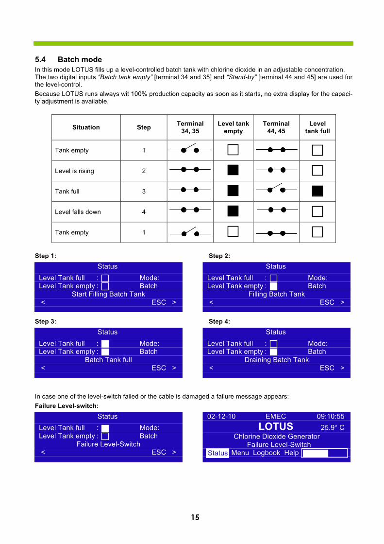
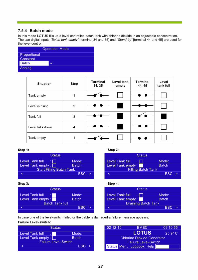
5.4 Batch mode In this mode LOTUS fills up a level-controlled batch tank with chlorine dioxide in an adjustable concentration. The two digital inputs “Batch tank empty” [terminal 34 and 35] and “Stand-by” [terminal 44 and 45] are used for the level-control. Because LOTUS runs always wit 100% production capacity as soon as it starts, no extra display for the capaci-ty adjustment is available.
Situation Step Terminal 34, 35
Level tank empty
Terminal 44, 45
Level tank full
Tank empty 1
Level is rising 2
Tank full 3
Level falls down 4
Tank empty 1
Step 1: Step 2:
Step 3: Step 4:
In case one of the level-switch failed or the cable is damaged a failure message appears: Failure Level-switch:
Status Level Tank full : Mode: Level Tank empty : Batch
Filling Batch Tank < ESC >
Status Level Tank full : Mode: Level Tank empty : Batch
Start Filling Batch Tank < ESC >
Status Level Tank full : Mode: Level Tank empty : Batch
Batch Tank full < ESC >
Status Level Tank full : Mode: Level Tank empty : Batch
Draining Batch Tank < ESC >
Status Level Tank full : Mode: Level Tank empty : Batch
Failure Level-Switch < ESC >
02-12-10 EMEC 09:10:55 LOTUS 25.9° C
Chlorine Dioxide Generator Failure Level-Switch
Status Menu Logbook Help Status
16
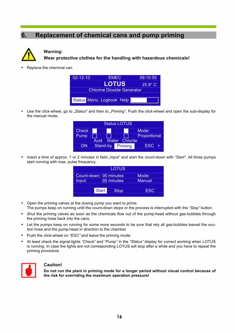
6. Replacement of chemical cans and pump priming
Warning: Wear protective clothes for the handling with hazardous chemicals!
• Replace the chemical can.
• Use the click-wheel, go to „Status“ and then to „Priming“. Push the click-wheel and open the sub-display forthe manual mode.
• Insert a time of approx. 1 or 2 minutes in field „Input“ and start the count-down with “Start”. All three pumpsstart running with max. pulse frequency.
• Open the priming valves at the dosing pump you want to prime.The pumps keep on running until the count-down stops or the process is interrupted with the “Stop” button.
• Shut the priming valves as soon as the chemicals flow out of the pump-head without gas-bubbles throughthe priming hose back into the cans.
• Let the pumps keep on running for some more seconds to be sure that rely all gas-bubbles leaved the suc-tion hose and the pump-head in direction to the chamber.
• Push the click-wheel on “ESC” and leave the priming mode.• At least check the signal-lights “Check” and “Pump” in the “Status” display for correct working when LOTUS
is running. In case the lights are not corresponding LOTUS will stop after a while and you have to repeat thepriming procedure.
Caution! Do not run the plant in priming mode for a longer period without visual control because of the risk for overriding the maximum operation pressure!
02-12-10 EMEC 09:10:55 LOTUS 25.9° C
Chlorine Dioxide Generator
Status Menu Logbook Help Status
Status LOTUS Check : Mode: Pump : Proportional
Acid Water Chlorite ON Stand-by Priming ESC > Priming
LOTUS Count-down: 00 minutes Mode: Input: 05 minutes Manual
Start Stop ESC Start
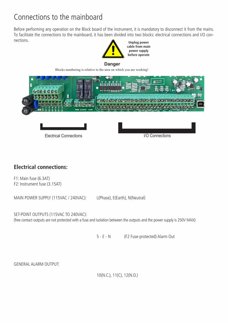
Connections to the mainboardBefore performing any operation on the Block board of the instrument, it is mandatory to disconnect it from the mains. To facilitate the connections to the mainboard, it has been divided into two blocks: electrical connections and I/O con-nections.
Electrical connections:
F1: Main fuse (6.3AT)F2: Instrument fuse (3.15AT)
MAIN POWER SUPPLY (115VAC / 240VAC): L(Phase), E(Earth), N(Neutral)
SET-POINT OUTPUTS (115VAC TO 240VAC): (free contact outputs are not protected with a fuse and isolation between the outputs and the power supply is 250V MAX):
5 - E - N (F2 Fuse-protected) Alarm Out
GENERAL ALARM OUTPUT:
10(N.C.), 11(C), 12(N .O.)
] ]Electrical Connections I/O Connections
Blocks numbering is relative to the area on which you are working!Danger
Unplug power cable from main
power supply before operate
L 1 2 3 4 5 6
E E E E E E E
N N N N N N N 7 8 9 10 11 12F1
F2
A B 1 2 3 4 5 6 7 8 9 10 11 12 13 14 15 16 17 18 19 20 21 22 23 24 25 26 27 28
29 30 31 32 33 34 35 36 37 38 39 40 41 42 43 44 45 46 47 48 49 50 51 52 53 54 55 56
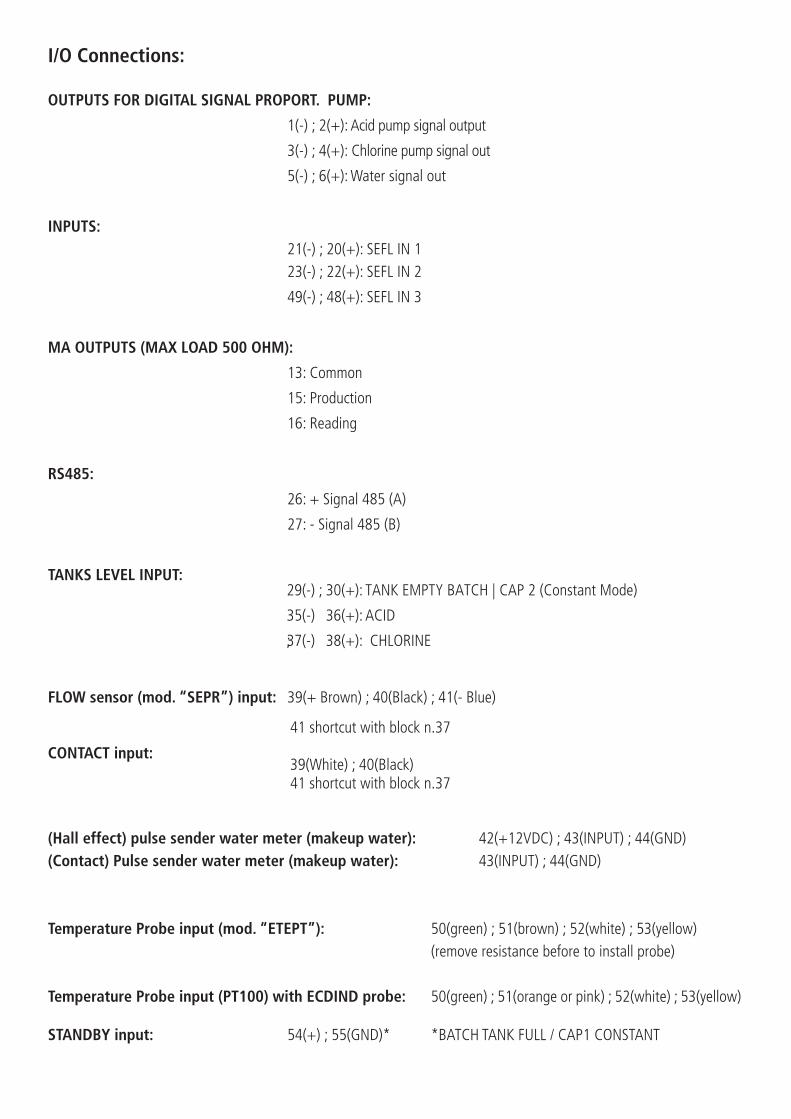
I/O Connections:
OUTPUTS FOR DIGITAL SIGNAL PROPORT. PUMP:
1(-) ; 2( + ): Acid pump signal output
3(-) ; 4( + ): Chlorine pump signal out
;5(-) 6(+): W ater signal out
INPUTS:21(-) ; 20(+): SEFL IN 123(-) ; 22(+): SEFL IN 2
49(-) ; 48(+): SEFL IN 3
MA OUTPUTS (MAX LOAD 500 OHM):
RS485:
TANKS LEVEL INPUT:
13: Common
15: Production
16: Reading
26: + Signal 485 (A)
27: - Signal 485 (B)
29(-) ; 30(+): TANK EMPTY BATCH | CAP 2 (Constant Mode)
35(-) 36(+): ACID
;37(-) 38(+): CHLORINE
FLOW sensor (mod. “SEPR”) input: 39(+ Brown) ; 40(Black) ; 41(- Blue)
CONTACT input:
41 shortcut with block n.37
39(White) ; 40(Black)41 shortcut with block n.37
(Hall effect) pulse sender water meter (makeup water): (Contact) Pulse sender water meter (makeup water):
42(+12VDC) ; 43(INPUT) ; 44(GND) 43(INPUT) ; 44(GND)
Temperature Probe input (mod. “ETEPT”): 50(green) ; 51(brown) ; 52(white) ; 53(yellow)(remove resistance before to install probe)
50(green) ; 51(orange or pink) ; 52(white) ; 53(yellow)Temperature Probe input (PT100) with ECDIND probe:
STANDBY input: 54(+) ; 55(GND)* *BATCH TANK FULL / CAP1 CONSTANT
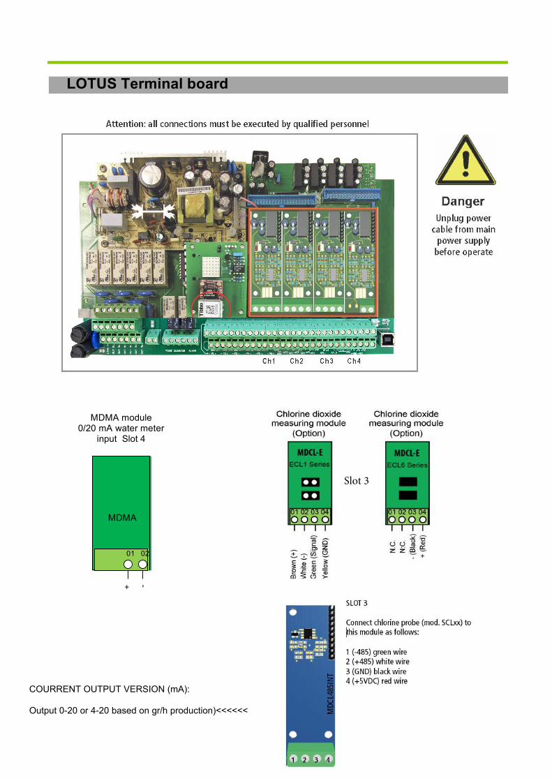
LOTUS Terminal board
MDMA module 0/20 mA water meter
input Slot 4
+ -
MDMA
01 02
Slot 3
COURRENT OUTPUT VERSION (mA):
Output 0-20 or 4-20 based on gr/h production)<<<<<<
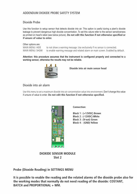
ADDENDUM DIOXIDE PROBE SAFETY SYSTEM
Dioxide Probe
Use this function to setup sensor that detects dioxide into air. This option is useful during a plant’s dioxide leakage to prevent dangerous high dioxide concentration. To set this valure refer to the sensor sensitiveness as printed on head’s label (see below picture). Do not edit this function if not otherwise specified or if unsure of value to enter.
Other options are: MAIN MENU: HIDE to not show a warning message. Use exclusively if no sensor is connected.MAIN MENU: SHOW to enable warning message and related alarm on main screen. Enabled by default.
Attention: this procedure assumes that the instrument is configured properly and connected to a working sensor, otherwise the results may not be reliable.
Dioxide into air alarm
Use this menu to set a maximum dioxide into air concentration value into environment. Don’t change this value if unsure of value to enter. Do not edit this function if not otherwise specified.
Dioxide into air main sensor head
Connection:
Block 1 : (+12VDC) BrownBlock 2 : (-12VDC) WhiteBlock 3 : (V-out) Green Block 4 : (GND) Yellow
DIOXIDE SENSOR MODULESlot 2
1 2 3 4
Probe (Dioxide Reading) in SETTINGS MENU
It is possible to enable the reading and the related alarms of the dioxide probe also for the working modes that normally do not need reading of the dioxide: COSTANT, BATCH and PROPORTIONAL + WM.
18
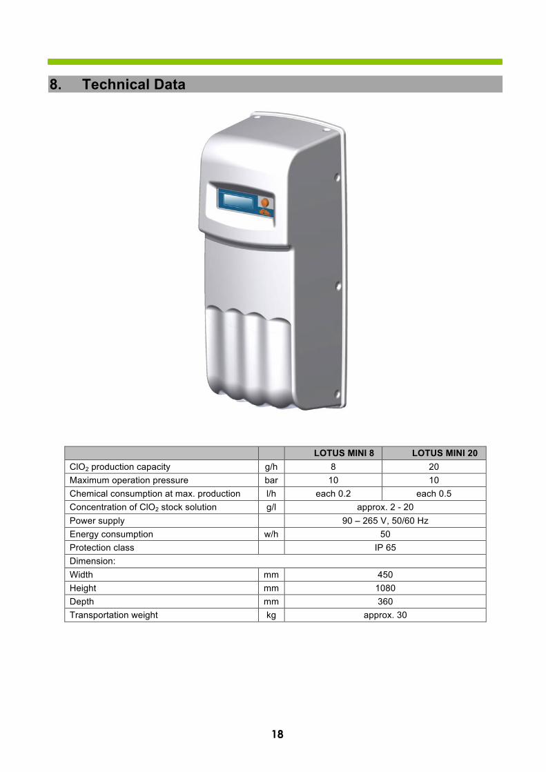
8. Technical Data
LOTUS MINI 8 LOTUS MINI 20 ClO2 production capacity g/h 8 20 Maximum operation pressure bar 10 10 Chemical consumption at max. production l/h each 0.2 each 0.5 Concentration of ClO2 stock solution g/l approx. 2 - 20 Power supply 90 – 265 V, 50/60 Hz Energy consumption w/h 50 Protection class IP 65 Dimension: Width mm 450 Height mm 1080 Depth mm 360 Transportation weight kg approx. 30
19
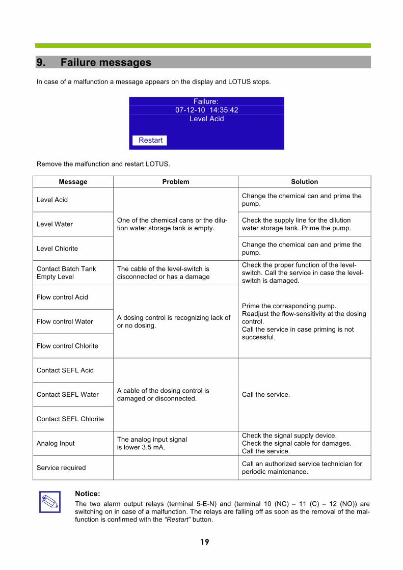
9. Failure messagesIn case of a malfunction a message appears on the display and LOTUS stops.
Remove the malfunction and restart LOTUS.
Message Problem Solution
Level Acid
One of the chemical cans or the dilu-tion water storage tank is empty.
Change the chemical can and prime the pump.
Level Water Check the supply line for the dilution water storage tank. Prime the pump.
Level Chlorite Change the chemical can and prime the pump.
Contact Batch Tank Empty Level
The cable of the level-switch is disconnected or has a damage
Check the proper function of the level-switch. Call the service in case the level-switch is damaged.
Flow control Acid
A dosing control is recognizing lack of or no dosing.
Prime the corresponding pump. Readjust the flow-sensitivity at the dosing control. Call the service in case priming is not successful.
Flow control Water
Flow control Chlorite
Contact SEFL Acid
A cable of the dosing control is damaged or disconnected. Call the service. Contact SEFL Water
Contact SEFL Chlorite
Analog Input The analog input signal is lower 3.5 mA.
Check the signal supply device. Check the signal cable for damages. Call the service.
Service required Call an authorized service technician for periodic maintenance.
Notice: The two alarm output relays (terminal 5-E-N) and (terminal 10 (NC) – 11 (C) – 12 (NO)) are switching on in case of a malfunction. The relays are falling off as soon as the removal of the mal-function is confirmed with the “Restart” button.
Failure: 07-12-10 14:35:42
Level Acid
Restart

COMMUNICATION
COMMUNICATION MENU (TCP/IP - GPRS with MODEM OR ETHERNET MODULE
This instrument can be controlled and programed remotely using the system called ERMES and a standard web browser (i.e.: Google Chrome or Safari). In order to use this service an internet connection is required (lan or wan) and user must configure the instrument to obtain a valid IP address (through a valid DHCP service or manually). If this instrument is installed within an office network please contact your system-administrator to obtain required parameters and eventually unlock TCP/IP port 2020.
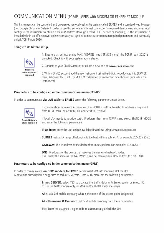
Things to do before setup.
1. Ensure that on instrument MAC ADDRESS (see SERVICE menu) the TCP/IP port 2020 isunlocked. Check it with your system-administrator.
2. Connect to your ERMES account or create a new one at: www.ermes-server.com
3. Within ERMES account add the new instrument using the 6 digits code located into SERVICE menu. (choose LAN DEVICE or MODEM code based on connection type choosen prior to buy the instrument)
Parameters to be configu ed in the communication menu (TCP/IP)
In order to communicate via LAN cable to ERMES server the following parameters must be set:
If configuration requires the presence of a ROUTER with automatic IP address assignment from TCP/IP menu select IP MODE and set it to DYNAMIC.
If local LAN needs to provide static IP address then from TCP/IP menu select STATIC IP MODE and enter the following parameters:
IP address: enter the unit unique available IP address using syntax xxx.xxx.xxx.xxx
SUBNET (netmask): range of belonging to the host within a subnet IP. For example: 255.255.255.0
GATEWAY: The IP address of the device that routes packets. For example: 192.168.1.1
DNS: IP address of the device that resolves the names of network nodes. It is usually the same as the GATEWAY. It can bel also a public DNS address (e.g.: 8.8.8.8)
Parameters to be configu ed in the communication menu (GPRS)
In order to communicate via GPRS modem to ERMES server insert SIM into modem’s slot the slot. A data plan subscription is suggestes to reduce SIM costs. From GPRS menu set the following parameters:
Ermes SERVER: select YES to activate the traffic data with Ermes server or select NO to use the GPRS modem only for SMA and/or EMAIL alerts messages.
APN: ask SIM mobile company what is the name of the access point designated
APN Username & Password: ask SIM mobile company both these parameters
PIN: Enter the assigned 4 digits code to automatically unlock the SIM
Network administrstor
required
Basic Network skills required
COMMUNICATION (MESSAGES Setup - RS485)This instrument can send emails and / or sms when a system failure or warning happens. If instrument is configured to operate through the LAN only email messages can be send. Otherwise if instruments has a mobile modem both SMS and emails messages can be send.
MESSAGES Setup
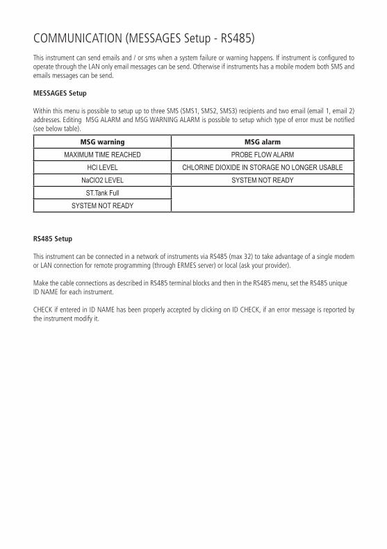
Within this menu is possible to setup up to three SMS (SMS1, SMS2, SMS3) recipients and two email (email 1, email 2) addresses. Editing MSG ALARM and MSG WARNING ALARM is possible to setup which type of error must be notified (see below table).
MSG warning MSG alarm
MAXIMUM TIME REACHED PROBE FLOW ALARMHCl LEVEL CHLORINE DIOXIDE IN STORAGE NO LONGER USABLE
NaClO2 LEVEL SYSTEM NOT READYST.Tank Full
SYSTEM NOT READY
RS485 Setup
This instrument can be connected in a network of instruments via RS485 (max 32) to take advantage of a single modem or LAN connection for remote programming (through ERMES server) or local (ask your provider).
Make the cable connections as described in RS485 terminal blocks and then in the RS485 menu, set the RS485 unique ID NAME for each instrument.
CHECK if entered in ID NAME has been properly accepted by clicking on ID CHECK, if an error message is reported by the instrument modify it.

33
COMMUNICATION (LOG MENU & LOGBOOK MENU)This function, when enabled, allows to record and send to ERMES server all instrument activities (date, time, temperature,
levels, alarms, totalizers, outputs status) for a set period (EVERY) and starting from a certain time (TIME) .
Note: SET TIME AND DATE PRIOR TO ENABLE THE LOG. If not fed after 30 days the instrument will lose current date
and time.
TIME: log starting time (format 23h 59min)
EVERY: frequency of recording (format 23h 59min)
E.g.: To set the instrument to begin logging events starting from 16:00 every hour set TOME to 16h: 00 and EVERY of 1h: 00m
Note: To view on instrument’s display the archived logs select LOGBOOK
ERMESThe web-based application ERMES allows plants remote control: with it is possibile to read, analize and modify instruments parameters from PCs, smartphones or tablets.
PLUS
• It reduces plant intervention and inspections.• It reports on the current status of the network’s devices and connections (probes, outputs, alarms, setpoints)• It instantly gives notification of alarms by sms or email• It generates an up to date report of all plant instruments• It can display the instruments activity log as line graphs and charts and it can download it to your pc in excel or
pdf format
HOW TO USE WEB ERMES
Enter the website www.ermes-server.com and, after registration, set plants.EMEC instruments with ETHERNET or GSM/GPRS Configuration will be immediatly connected and available for remote control. Furthermore, with ERMES you can receive alarm messages via email, with different report option on instrument status. If instrument has been bought with the GSM/GPRS option it’s possible to receive SMS reports on any mobile phone.
Read “COMMUNICATION” chapters to better understand how to configu e the instrument.

Troubleshooting
Problem Possible solution
What to do before to install the SIM into instru-ment’s modem
Check best signal coverage for operator choice.
Modem is compatible with the following GSM frequencies: 900 -1800 -1900 MHz (three-band). Not compatible with 3G only
operators.
SIM type is: Mini-SIM (classica SIM card in uso nei telefoni)
Lenght 25 (mm) - Width 15 (mm) - thickness 0,76 (mm)
Subscribe to a data plan for monthly traffic activity of about 500MB
Make sure PIN REQUEST is OFF. If not insert SIM into a standard mobile phone and disable it.
Several instruments are connected in RS485 mode but the software displays only one
Make sure the termination jumper on the first and last instrument of the chain are closed
The GPRS modem does not connect to the network
Verify the correct insertion of the SIM
Verify APN parameters and enter them manually if necessary
Make sure the SIM has a data plan active for internet access
Make sure the provider supports international roaming DATA if the connection is abroad
The instrument is unable to obtain a valid IP ad-dress from the LAN or the software does not
connect to it
Make sure the pre-existing network allows auto-assignment of the IP address (automatic DHCP); if it does not, contact the network
administrator to obtain the data to enter manually
Make sure the network cable is connected to the instrument. Make sure it is a good quality cable and not the “cross” type.
CAT 5, 6 and 7 cable types are compatibles
ERMES does not find the instruments via internet that are correctly connected to a LAN
Make sure the internet connection is active
Make sure there are no port-blocking third part programs and/or firewalls active that prevent data traffic through the TCP 2020 port
FIRST TIME CONNECTION TO ERMES
ERMES is asking for CODE and SERIAL NUMBER during first time access, where are they ?
CODE and SERIAL NUMBER are located on instrument’s main label
ADDING AN INSTRUMENT TO ERMES
Where is the CODE NUMBER required to add an instrument to the account?
For instrument with LAN access: see SERVICE menu within instrument’s software
For instrument with GPRS access: enter SIM phone number
MODBUSModbus is a serial communications protocol originally published by Modicon (now Schneider Electric) in 1979 for use with its programmable logic controllers (PLCs). Simple and robust, it has since become a de facto standard communication protocol, and it is now a commonly available means of connecting industrial electronic devices.
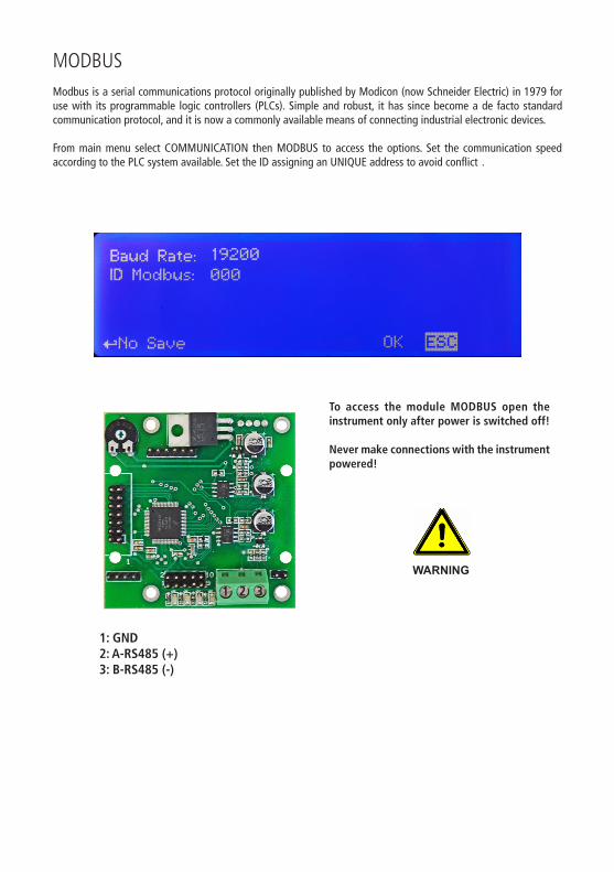
From main menu select COMMUNICATION then MODBUS to access the options. Set the communication speed according to the PLC system available. Set the ID assigning an UNIQUE address to avoid conflict .
1 2 3
1: GND2: A-RS485 (+)3: B-RS485 (-)
To access the module MODBUS open the instrument only after power is switched off!
Never make connections with the instrument powered!
WARNING

20
Appendix A: Test Certificate
Order No.:
LOTUS type: Serial No.:
Software release:
Chamber: Test pressure: Test temperatur Test period:
bar ° C hours
Dosing pumps: Acid Water Chlorite
Type:
Calibration value: ml ml ml
Calibration pressure: bar
Number of strokes:
System settings:
Dos-Check:
Pass-Code 2: Default:
Pass-Code 1: Default:
Language Deutsch / English
Water meter: Pulse/Liter Liter/Pulse
Max. value: m³/h at 20 mA
Date Signature


R3-10-14 21

R3-10-14 1
Chlorine Dioxide Generator LOTUS MINI
Installation and Operation Manual
Read this manual completely before you start with the installation and start-up. Do not trash this manual and store it nearby the generator for later use.
This manual contains important information about the installation and operation safety. Take care about the following instructions to avoid personal injuries and material damages! The operator is responsible in case of damages caused by installation and operation failures!
English

R3-10-14 2
3
Directory 1. General Safety Guidelines 4 1.1 Symbols 4 1.2 Safety instructions 4 1.3 CE-Conformity 5
2. General Description 6
3. Construction 7 3.1 Construction overview 7 3.2 Description and details 7
4. Installation 8 4.1 General requirements for the installation location 8 4.2 Requirements to the water 9 4.3 Assembly 9 4.4 Hydraulic installation 10 4.4.1 Installation to a pressure system 10 4.4.2 Installation to a batch tank 13 4.5 Electric Installation 15 4.5.1 Power supply 15 4.5.2 Types of Control 15
5. First Startup 16 5.1 Preparations 16 5.2 Hydraulic start-up 16
6. „LOTUS“ - Controller 17 6.1 Start display 17 6.2 Main display 17 6.3 Control element „Click-Wheel“ 18 6.4 Status displays 19 6.5 Logbook 20 6.6 Help 20
7. Main Menu 21 7.1 Pumps – Calibration of the dosing pumps 22 7.2 Probes – Calibration of the chlorine dioxide probe and temperature sensor 22 7.3 Contact water meter 23 7.4 Analog outputs 24 7.5 Operation mode 25 7.5.1 Proportional mode 26 7.5.2 Constant mode 27 7.5.3 Analog mode 27 7.5.4 Batch mode 28 7.5.5 Proportional & Measuring mode 29 7.6 System settings 30
9. LOTUS Terminal board 31
10. Technical Data 32
11 Failure Messages 33
Appendix A: Test Certificate
4
1. General Safety Guidelines
1.1 General remarks This manual includes basic directions for the assembling, operation and maintenance. Therefore it is obligatory for the assembly technician as well as for the operator to study the complete manual before starting with the installation and start-up. This manual must be present at the generator at any time. It is also obligatory for the operator to consider the general directions in chapter “Safety instructions” as well as the specific safety instructions included in the other chapters of this manual.
Notice: • For some of the following described functions additional accessories (not included in the delivery
scope of LOTUS) may be required.• Depending to the software release of the LOTUS-controller some of the described features may
not be available. Or some functions are available, but not described in this manual. Please contactyour dealer in case of the requirement for more information.
1.2 Symbols In accordance to the guideline DIN 4844-W9 about the characterization of special risks all safety instructions in this manual are labeled with the following symbols:
Warning: This symbol is waring about risks. Disregarding may cause heavy personal injuries and material damages.
Caution! This symbol is warning about troubles caused by incorrect operation.
Notice or advice: This symbol shows important additional information.
1.3 Safety instructions The appropriate use of the LOTUS generator is described in this manual.
Warning: • The un-appropriate use affects the safety function of this generator and other connected devices
and is therefore strictly forbidden.• Assembling and maintenance has to be done by authorized technicians only.
• Maintenance repairs have to be executed only by the manufacturer or authorized technicians. Inter-ventions or changes at the device in opposite to the regular maintenance in accordance to thismanual are incorrect and make the all warranty claims nugatory.
• The operator is liable for the observance of the local safety instructions.
• For the operation and service the device must be accessible at all times.
Warning: risk of explosion

5
• Before starting service at the dosing pumps make the pump-heads pressure-less.
• Drain and flush the pump-heads with clean water before starting the service.
• Take attention to the chemical safety data sheets!
• Wear protection clothes for the handling with unknown and hazardous chemicals.
6
Directions for the operator (Specific information for applicable regulations in Germany): • Accident prevention regulation (UVV) „Chlorination of water“, GUV V-D5 E.• „Dosing plants for chlorine dioxide“, DVGW guideline W 624 (latest version respectively).• „Chlorine dioxide in water treatment“, DVGW worksheet W 224 (latest version respectively).• Guidelines for the protection of groundwater against polution.
(§ 19 Federal Water Act – WHG dated 23.9.1986).• Ordinance of hazardous substances (GefStoffV) – especially § 17 (obligatory protection)
and § 20 (operation instruction).
1.4 CE - Conformity
The LOTUS generator is corresponding to the following EU-standards:
The following standards are considered: • Machinery directive 89/392/EWG IIA inclusive all actual changes within the year of
Manufacturing 91/368/EWG – Mod. 1, and 93/44/EWG – Mod. 2.• Guideline 2004/108 EG about the electromagnetic tolerance of electric equipment.• Low-voltage directive 2006/95/EG.• EC – Pressure Equipment Directive (97/23/EG)
The following harmonized safety guidelines are considered: • UNI EN 292/1 – Safety of machines• UNI EN 292/2 – Safety of machines; technical principles.• CEI EN 60204-1-98 – General requirements for electric equipment in machines.
Notice: A declaration of conformity can be ordered from the manufacturer.
7
2. General DescriptionThe chlorine dioxide generator is used for the production of liquid chlorine dioxide. This disinfection agent kills all bacteria, germs, viruses and fungi within shortest time – and it works with very low concentration. The generator is working with the hydrochloric acid – chlorite process and uses diluted chemicals like hydro-chloric acid (HCl 9%) and sodium chlorite (NaClO2 7.5%) in accordance to the following chemical equation:
Hydrochloric acid + Sodium Chlorite = Chlorine dioxide + Sodium chloride + Water 4 HCl + 5 NaClO2 = 4 ClO2 + 5 NaCl + 2 H2O
In the process each chemical is pumped with a specific proportion into a reactor vessel [ 5 ] by two dosing pumps [ 2 and 4 ]. Each stroke from each pump is triggered by the LOTUS-controller [ 1 ] and counter-controlled by a “SEFL” [ 6 ]. Inside the reactor vessel the chemicals are reacting to chlorine dioxide with a concentration of 2% (= 20 g/l). In the next step a specific proportion of water is pumped into the reactor by a third dosing pump [ 3 ] to dilute the chlorine dioxide down to a concentration of approx. 2 g/l. The finished chlorine dioxide leaves the reactor vessel through a back pressure valve [ 7 ] on the top of the re-actor.
The advantages are: • The chlorine dioxide can be pumped direct into pressurized systems with the pressure of the pumps and
likewise into pressure-less storing tanks, to distribute the disinfection to different points of use.• The System can work in proportional mode with contact water meter, current signal or chlorine dioxide
measurement.
1
2 3 4
5
6
7
8
3. Construction
3.1 Construction overview
3.2 Description and details 1 LOTUS-controller 10 Drain nozzle ½“ 2 Dosing pump for hydrochloric acid (HCl 9%) 11 Level switch „Dilution water tank empty“ 3 Dosing pump for dilution water 12 Can with hydrochloric acid 9 % (ca. 95 g/l) 4 Dosing pump for sodium chlorite (NaClO2 7,5%) 13 Suction lance with level-switch „Hydrochloric acid“ 5 Reactor 14 Can with sodium chlorite 7,5 % (ca. 80 g/l) 6 Dosing control “SEFL” 15 Suction lance with level-switch „Sodium chlorite“
each for hydrochloric acid, sodium chlorite and dilution water 7 PVDF check-valve with hose-connection 4x6 mm 8 Storage tank for dilution water
(located behind the dosing pumps) 9 Floating valve
A Hose-connection 4x6 mm for dilution water B Hose-connection 4x6 mm for chlorine dioxide (for PVDF hose) C Dilution water storage tank overflow
1
2
3
4
5
6
7
HCl 9% NaClO2 7,5%
8
10
9
11
C
12
13
14
15
B
A
A
9
4. Installation
Warning: • For the operation of the LOTUS generator the absolute observance of the national and local
regulations is required. The operator is liable for the observance of the local safety instructions.
• The generator must be installed and started up in accordance to the regulations in this manual.• The usage of installation parts not approved by the manufacturer or supplier is prohibited.• The operation of the generator is allowed only with suitable safety-valves approved by the
manufacturer. The contempt of this regulation results the ultimate loss of any warranty claims!• Before starting works at the plant decompress all parts of the system.• The plant never has to work against closed valves because of the risk of bursting hoses or
pipes.• Disconnect the power supply before opening the controller housing.• Take care of all national regulations during installation!
4.1 General requirements to the installation location
Notice • The plant must not be placed outdoors.• The plant must be protected against unauthorized access.• The installation location must be protected against sunlight and frost and well ventilated.• For temperatures less than 10° C suitable tempering systems are required.• It must be possible to carry the chemical cans to the plant without any restrictions.• An escape route is stringent required!• The plant must be mounted onto a vertical solid wall without tensions.• The plant must be mounted in a way that no vibrations can be produced.• Take care of free entrance from all sides for the operation and maintenance!• A tap-valve and a lockable floor gully should be present for the risk-free removal of spilled
chemicals.• A fuse-protected power-supply (230 V CE-connector, 16 A) is required.
10
4.2 Requirements for the water
Warning: Serious malfunctions at the plant or corrosion damages in the pipe-work of the treated wa-ter should be possible in case the following requirements to the water the chlorine dioxide is produced for as well as for the dilution water are not fulfilled: Dilution water: Temperature: 10 – 30° C Pressure: 0.3 - 1 bar Quality: Free of iron, manganese and particles, non-corrosive. Treated water: Temperature: > 5°C Pressure: 6 bar max.
The following directions are based on a concentration for chlorine dioxide of 0.4 mg/l to prevent pipe-corrosion: • The pH-level should be always higher than pH 6.5.
It should be controlled during operation. • In case the carbonate hardness is lower 1.1° dH (German hardness) or the alkalinity is lower
0.4 mMol/l the dosing of suitable chemicals for the increase of the pH-level is required. • In case the carbonate hardness is lower 19° dH (German hardness) the installation place of the
injection valve for the chlorine dioxide (already made of PVDF) should be made of corrosion resistance materials (like PVC).
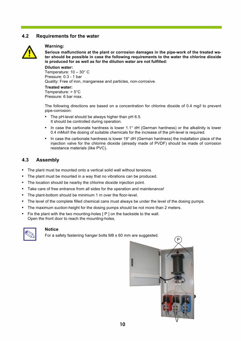
4.3 Assembly
• The plant must be mounted onto a vertical solid wall without tensions.• The plant must be mounted in a way that no vibrations can be produced.• The location should be nearby the chlorine dioxide injection point.• Take care of free entrance from all sides for the operation and maintenance!• The plant-bottom should be minimum 1 m over the floor-level.• The level of the complete filled chemical cans must always be under the level of the dosing pumps.• The maximum suction-height for the dosing pumps should be not more than 2 meters.• Fix the plant with the two mounting-holes [ P ] on the backside to the wall.
Open the front door to reach the mounting-holes.
Notice For a safety fastening hanger bolts M8 x 60 mm are suggested.
P
11
4.4 Hydraulic Installation
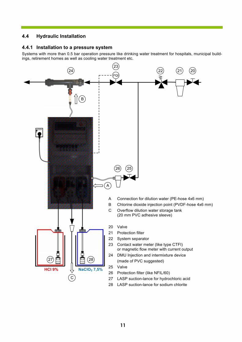
4.4.1 Installation to a pressure system Systems with more than 0.5 bar operation pressure like drinking water treatment for hospitals, municipal build-ings, retirement homes as well as cooling water treatment etc.
A Connection for dilution water (PE-hose 4x6 mm) B Chlorine dioxide injection point (PVDF-hose 4x6 mm) C Overflow dilution water storage tank
(20 mm PVC adhesive sleeve)
20 Valve 21 Protection filter 22 System separator 23 Contact water meter (like type CTFI)
or magnetic flow meter with current output 24 DMU Injection and intermixture device
(made of PVC suggested) 25 Valve 26 Protection filter (like NFIL/60) 27 LASP suction-lance for hydrochloric acid 28 LASP suction-lance for sodium chlorite
HCl 9% NaClO2 7,5%
27 28
20 21 22 23
24
25 26
FQI
C
B
A
12
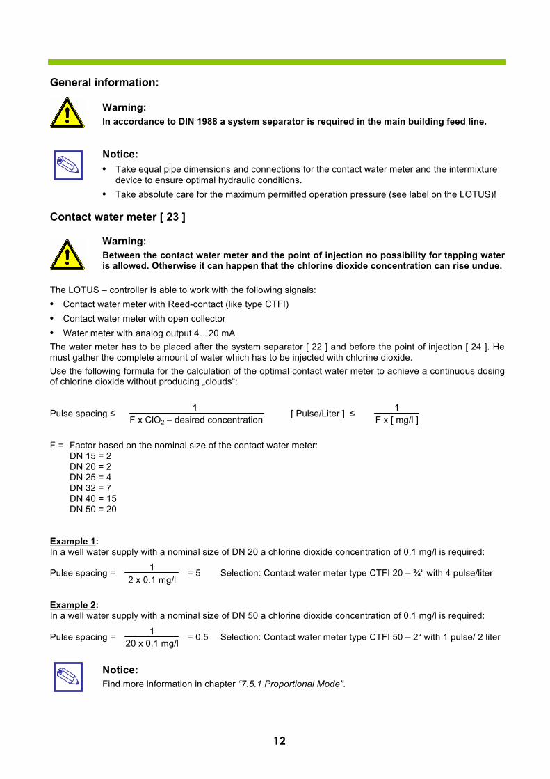
General information:
Warning: In accordance to DIN 1988 a system separator is required in the main building feed line.
Notice: • Take equal pipe dimensions and connections for the contact water meter and the intermixture
device to ensure optimal hydraulic conditions.• Take absolute care for the maximum permitted operation pressure (see label on the LOTUS)!
Contact water meter [ 23 ]
Warning: Between the contact water meter and the point of injection no possibility for tapping water is allowed. Otherwise it can happen that the chlorine dioxide concentration can rise undue.
The LOTUS – controller is able to work with the following signals: • Contact water meter with Reed-contact (like type CTFI)• Contact water meter with open collector• Water meter with analog output 4…20 mAThe water meter has to be placed after the system separator [ 22 ] and before the point of injection [ 24 ]. He must gather the complete amount of water which has to be injected with chlorine dioxide. Use the following formula for the calculation of the optimal contact water meter to achieve a continuous dosing of chlorine dioxide without producing „clouds“:
Pulse spacing ≤ [ Pulse/Liter ] ≤
F = Factor based on the nominal size of the contact water meter: DN 15 = 2 DN 20 = 2 DN 25 = 4 DN 32 = 7 DN 40 = 15 DN 50 = 20
Example 1: In a well water supply with a nominal size of DN 20 a chlorine dioxide concentration of 0.1 mg/l is required:
Pulse spacing = = 5 Selection: Contact water meter type CTFI 20 – ¾“ with 4 pulse/liter
Example 2: In a well water supply with a nominal size of DN 50 a chlorine dioxide concentration of 0.1 mg/l is required:
Pulse spacing = = 0.5 Selection: Contact water meter type CTFI 50 – 2“ with 1 pulse/ 2 liter
Notice: Find more information in chapter “7.5.1 Proportional Mode”.
1 F x [ mg/l ]
1 2 x 0.1 mg/l
1 20 x 0.1 mg/l
1 F x ClO2 – desired concentration
13
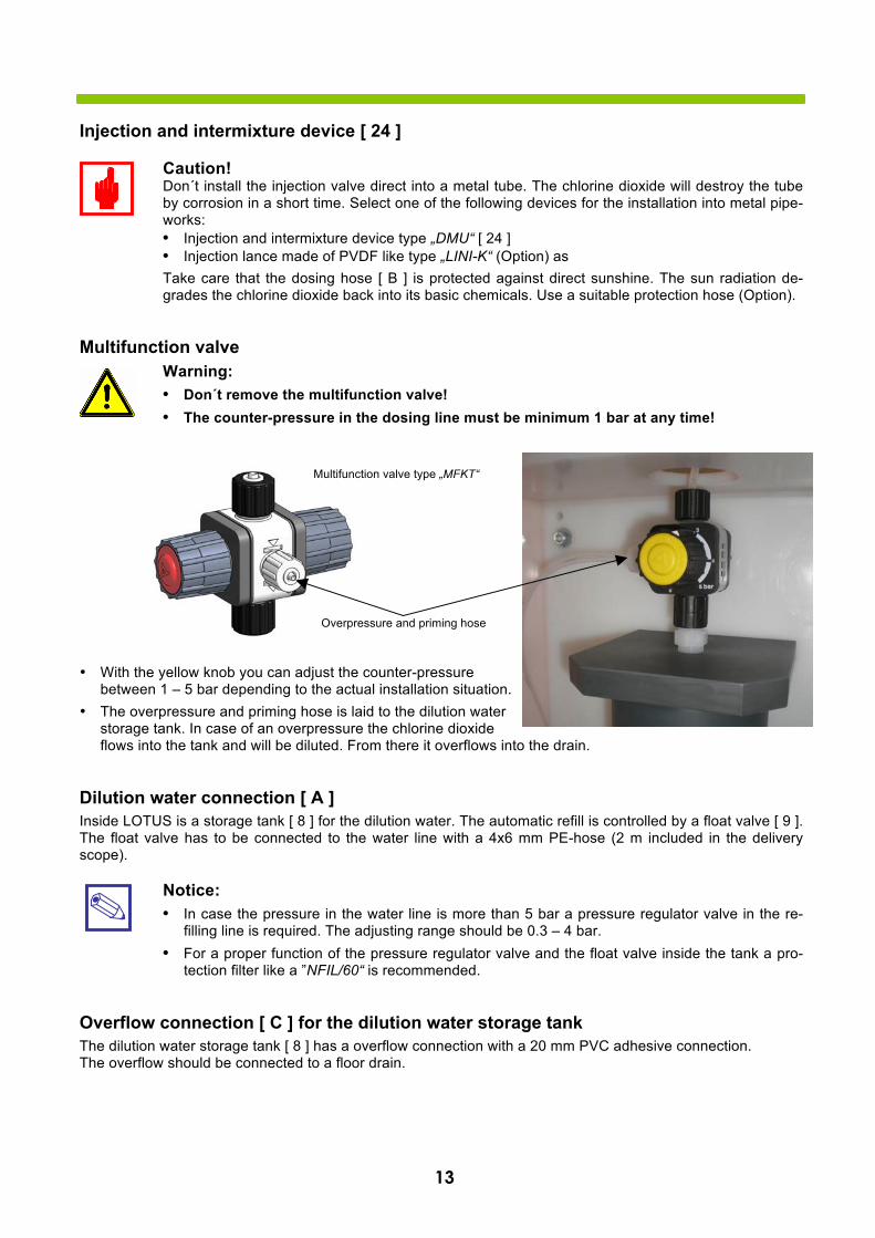
Injection and intermixture device [ 24 ]
Caution! Don´t install the injection valve direct into a metal tube. The chlorine dioxide will destroy the tube by corrosion in a short time. Select one of the following devices for the installation into metal pipe-works: • Injection and intermixture device type „DMU“ [ 24 ]• Injection lance made of PVDF like type „LINI-K“ (Option) asTake care that the dosing hose [ B ] is protected against direct sunshine. The sun radiation de-grades the chlorine dioxide back into its basic chemicals. Use a suitable protection hose (Option).
Multifunction valve Warning: • Don´t remove the multifunction valve!• The counter-pressure in the dosing line must be minimum 1 bar at any time!
• With the yellow knob you can adjust the counter-pressurebetween 1 – 5 bar depending to the actual installation situation.
• The overpressure and priming hose is laid to the dilution waterstorage tank. In case of an overpressure the chlorine dioxideflows into the tank and will be diluted. From there it overflows into the drain.
Dilution water connection [ A ] Inside LOTUS is a storage tank [ 8 ] for the dilution water. The automatic refill is controlled by a float valve [ 9 ]. The float valve has to be connected to the water line with a 4x6 mm PE-hose (2 m included in the delivery scope).
Notice: • In case the pressure in the water line is more than 5 bar a pressure regulator valve in the re-
filling line is required. The adjusting range should be 0.3 – 4 bar.• For a proper function of the pressure regulator valve and the float valve inside the tank a pro-
tection filter like a ”NFIL/60“ is recommended.
Overflow connection [ C ] for the dilution water storage tank The dilution water storage tank [ 8 ] has a overflow connection with a 20 mm PVC adhesive connection. The overflow should be connected to a floor drain.
Overpressure and priming hose
Multifunction valve type „MFKT“
14
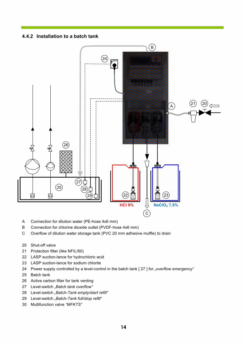
4.4.2 Installation to a batch tank
A Connection for dilution water (PE-hose 4x6 mm) B Connection for chlorine dioxide outlet (PVDF-hose 4x6 mm) C Overflow of dilution water storage tank (PVC 20 mm adhesive muffle) to drain
20 Shut-off valve 21 Protection filter (like NFIL/60) 22 LASP suction-lance for hydrochloric acid 23 LASP suction-lance for sodium chlorite 24 Power supply controlled by a level-control in the batch tank [ 27 ] for „overflow emergency“ 25 Batch tank 26 Active carbon filter for tank venting 27 Level-switch „Batch tank overflow“ 28 Level-switch „Batch-Tank empty/start refill“ 29 Level-switch „Batch-Tank full/stop refill“ 30 Multifunction valve “MFKTS”
HCl 9% NaClO2 7,5%
22 23
26
25
20 21
C
B
A
27
28 29
24
15
Caution! Take care that the “MFKTS” – multifunction valve on the top of the reactor (inside LOTUS) is adjusted with a counter-pressure of minimum 1 bar!
Dilution water connection [ A ] Inside LOTUS is a storage tank [ 8 ] for the dilution water. The automatic refill is controlled by a float valve [ 9 ]. The float valve has to be connected to the water line with a 4x6 mm PE-hose (2 m included in the delivery scope).
Notice: • In case the pressure in the water line is more than 5 bar a pressure regulator valve in the re-
filling line is required. The adjusting range should be 0.3 – 4 bar.• For a proper function of the pressure regulator valve and the float valve inside the tank a pro-
tection filter like a ”NFIL/60“ is recommended.
Overflow connection [ C ] for the dilution water storage tank The dilution water storage tank [ 8 ] has a overflow connection with a 20 mm PVC adhesive connection. The overflow should be connected to a floor drain.
16
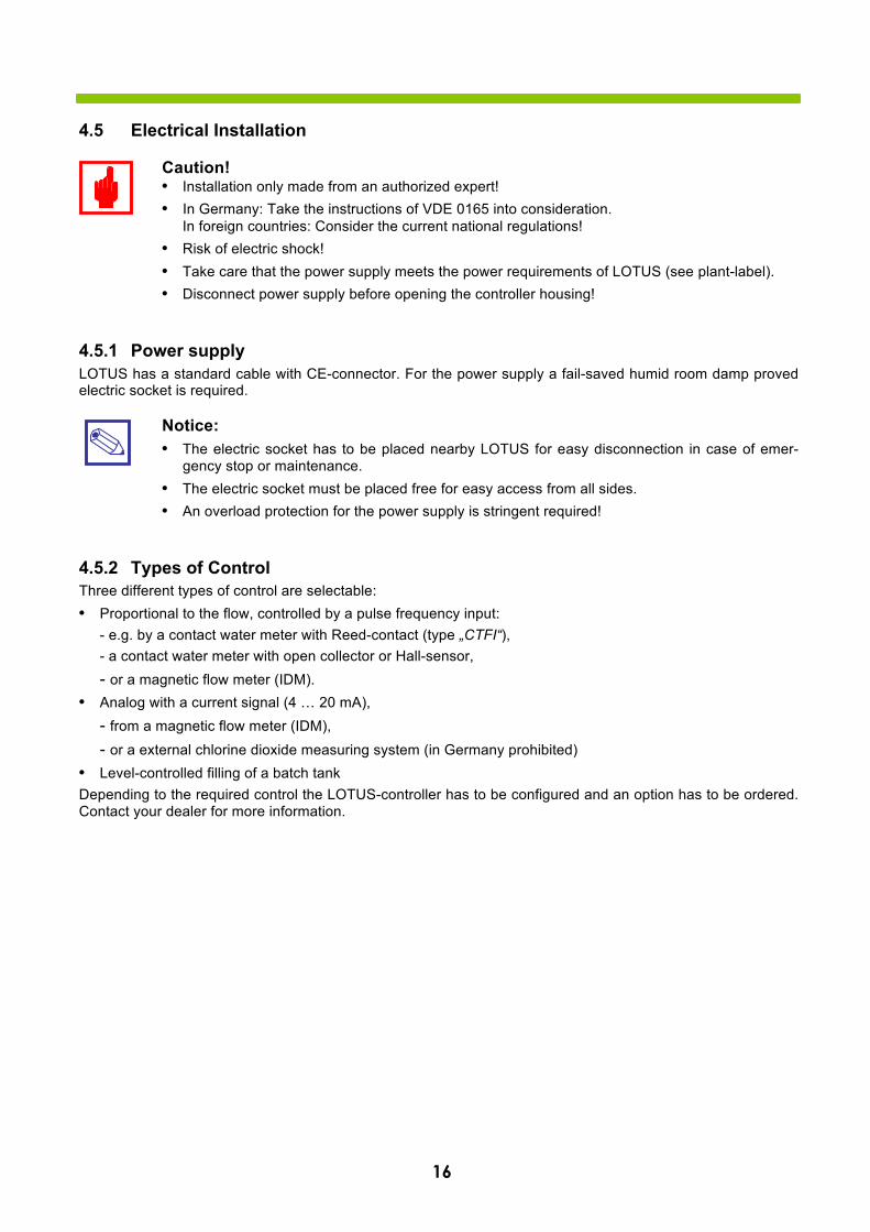
4.5 Electrical Installation
Caution! • Installation only made from an authorized expert!• In Germany: Take the instructions of VDE 0165 into consideration.
In foreign countries: Consider the current national regulations!• Risk of electric shock!• Take care that the power supply meets the power requirements of LOTUS (see plant-label).• Disconnect power supply before opening the controller housing!
4.5.1 Power supply LOTUS has a standard cable with CE-connector. For the power supply a fail-saved humid room damp proved electric socket is required.
Notice: • The electric socket has to be placed nearby LOTUS for easy disconnection in case of emer-
gency stop or maintenance.• The electric socket must be placed free for easy access from all sides.• An overload protection for the power supply is stringent required!
4.5.2 Types of Control Three different types of control are selectable: • Proportional to the flow, controlled by a pulse frequency input:
- e.g. by a contact water meter with Reed-contact (type „CTFI“),- a contact water meter with open collector or Hall-sensor,- or a magnetic flow meter (IDM).
• Analog with a current signal (4 … 20 mA),- from a magnetic flow meter (IDM),- or a external chlorine dioxide measuring system (in Germany prohibited)
• Level-controlled filling of a batch tankDepending to the required control the LOTUS-controller has to be configured and an option has to be ordered. Contact your dealer for more information.
17
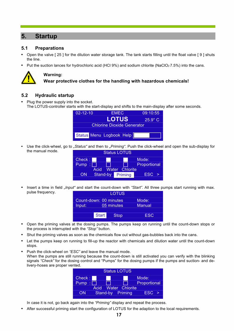
5. Startup
5.1 Preparations • Open the valve [ 25 ] for the dilution water storage tank. The tank starts filling until the float valve [ 9 ] shuts
the line. • Put the suction lances for hydrochloric acid (HCl 9%) and sodium chlorite (NaClO2 7.5%) into the cans.
Warning: Wear protective clothes for the handling with hazardous chemicals!
5.2 Hydraulic startup • Plug the power supply into the socket.
The LOTUS-controller starts with the start-display and shifts to the main-display after some seconds.
• Use the click-wheel, go to „Status“ and then to „Priming“. Push the click-wheel and open the sub-display forthe manual mode.
• Insert a time in field „Input“ and start the count-down with “Start”. All three pumps start running with max.pulse frequency.
• Open the priming valves at the dosing pumps. The pumps keep on running until the count-down stops orthe process is interrupted with the “Stop” button.
• Shut the priming valves as soon as the chemicals flow out without gas-bubbles back into the cans.• Let the pumps keep on running to fill-up the reactor with chemicals and dilution water until the count-down
stops.• Push the click-wheel on “ESC” and leave the manual mode.
When the pumps are still running because the count-down is still activated you can verify with the blinkingsignals “Check” for the dosing control and “Pumps” for the dosing pumps if the pumps and suction- and de-livery-hoses are proper vented.
In case it is not, go back again into the “Priming” display and repeat the process. • After successful priming start the configuration of LOTUS for the adaption to the local requirements.
02-12-10 EMEC 09:10:55 LOTUS 25.9° C
Chlorine Dioxide Generator
Status Menu Logbook Help Status
Status LOTUS Check : Mode: Pump : Proportional
Acid Water Chlorite ON Stand-by Priming ESC > Priming
LOTUS Count-down: 00 minutes Mode: Input: 05 minutes Manual
Start Stop ESC Start
Status LOTUS Check : Mode: Pump : Proportional
Acid Water Chlorite ON Stand-by Priming ESC >
18
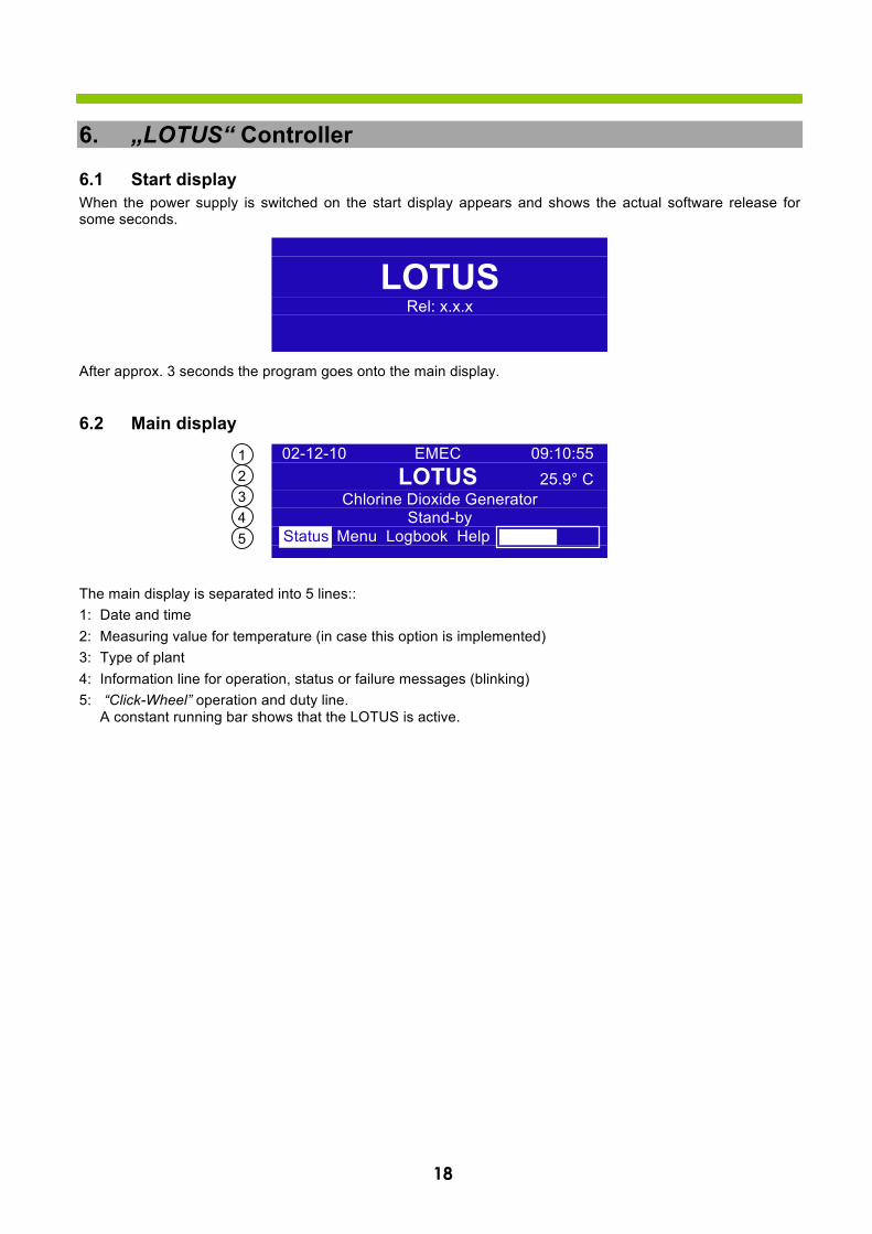
6. „LOTUS“ Controller
6.1 Start display When the power supply is switched on the start display appears and shows the actual software release for some seconds.
After approx. 3 seconds the program goes onto the main display.
6.2 Main display
The main display is separated into 5 lines:: 1: Date and time 2: Measuring value for temperature (in case this option is implemented) 3: Type of plant 4: Information line for operation, status or failure messages (blinking) 5: “Click-Wheel” operation and duty line.
A constant running bar shows that the LOTUS is active.
LOTUSRel: x.x.x
1 2 3 4 5
02-12-10 EMEC 09:10:55 LOTUS 25.9° C
Chlorine Dioxide Generator Stand-by
Status Menu Logbook Help Status
19
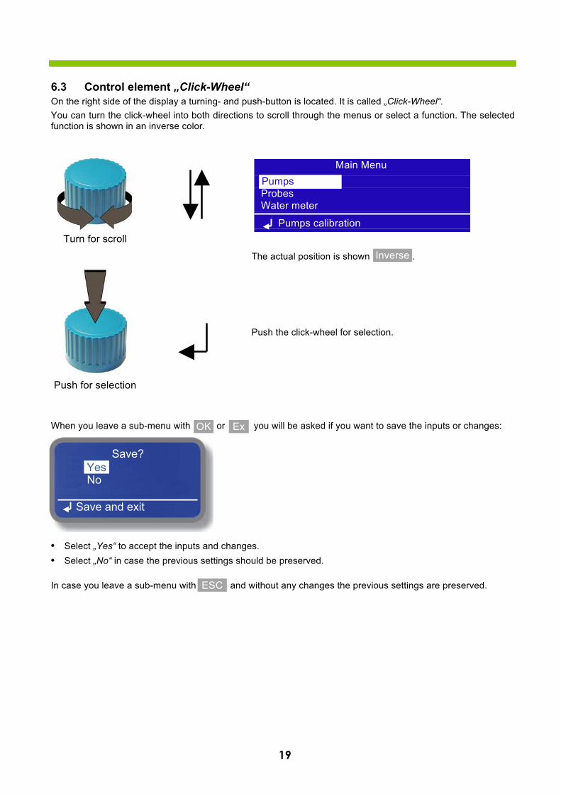
6.3 Control element „Click-Wheel“ On the right side of the display a turning- and push-button is located. It is called „Click-Wheel“. You can turn the click-wheel into both directions to scroll through the menus or select a function. The selected function is shown in an inverse color.
The actual position is shown .
Push the click-wheel for selection.
When you leave a sub-menu with or you will be asked if you want to save the inputs or changes:
• Select „Yes“ to accept the inputs and changes.• Select „No“ in case the previous settings should be preserved.
In case you leave a sub-menu with and without any changes the previous settings are preserved.
Inverse
OK Ex
ESC
Save? Yes No
Save and exit
Yes
Main Menu Proportional Probes Water meter
Pumps calibration
Pumps
Turn for scroll
Push for selection

20
6.4 Status Displays
Push the click-wheel on “Status” to open 4 different operation displays:
Check: The signal lights are showing the function of the dosing controls. At stagnant production the signal light shows . During production the signal lights from the dosing controls “Check” are blinking inverse corresponding to the signals from the „Pump“. That means: in the moment when a pump is doing a stroke (light = ), the light of the dosing control has to show .
Pump: See also „Check“. Mode: Shows the activated operation mode. Production: Shows the actual chlorine dioxide production capacity. Water Meter: Shows the actual flow capacity of the contact water meter. Next Service: Shows the remaining time until the next service is required. Operating hours: Shows the operating hours counter.
In the operation displays you have different options: ON/OFF Start/Stop LOTUS STAND-BY Switches LOTUS into the “Stand-by” mode,
independent to the function of the “Stand-by” – Input PRIMING Opens the display for dosing pumps priming resp. for manual mode ESC Go back to the main display < or > Scroll in the operation displays
Status LOTUS Production [g/h] : 4.25 Mode: Water Meter [m³/h]: 42.5 Proportional
< ESC > On
Totalizer Acid [ltr.] : 9123.5 Mode: Chlorite [ltr.]: 9124.9 Proportional Water Meter [m³]: 99999.9 < ESC On
Status LOTUS Next Service in [h]: 4375 Mode: Operating hours [h]: 9999999 Proportional
< ESC > On
02-12-10 EMEC 09:10:55 LOTUS 25.9° C
Chlorine Dioxide Generator Stand-by
Status Menu Logbook Help Status
Status LOTUS Check : Mode: Pump : Proportional
Acid Water Chlorite ON Stand-by Priming ESC >

21
6.5 Logbook
Turn the click-wheel onto the field “Logbook” and push it to open the sub-menu.
The LOTUS-controller has an internal logbook-memory. Two different types of data are stored together with a time-stamp: Operation data in periodic intervals and failure messages as soon as they appear.
Turn the click-wheel to scroll forward and backwards through the logbook. Push the click-wheel on “ESC” for return to the main display.
6.6 Help
Turn the click-wheel onto the field “Help” and push it to open the “Help” display.
The “Help” display shows the contact data of your dealer. Push the click-wheel on “ESC” for the return to the main display.
Logbook ˄
07-12-10 23:59:59 Mode: Proportional Acid:109.0 l Chlorite: 109.7 l Water: 298.6 m³
˅ ESC
Logbook ˄
07-12-10 12:35:55 Failure level acid 07-12-10 13:10:20 Restart
˅ ESC
LOTUS LIQUID Water Treatment
Phone: 01234-567890
ESC
02-12-10 EMEC 09:10:55 LOTUS 25.9° C
Chlorine Dioxide Generator Stand-by
Status Menu Logbook Help Logbook
02-12-10 EMEC 09:10:55 LOTUS 25.9° C
Chlorine Dioxide Generator Stand-by
Status Menu Logbook Help Help

22
7. Main Menu
Push the click-wheel to open the main menu. The access to the main menu is protected by a passcode:
Select a four-digit number-code. As soon as the fourth correct digit is selected the main menu opens automati-cally.
Caution! • Access to the main menu for authorized service technicians only!• The passcode is stored in appendix A: “Test Certificate”
or you find it in chapter „7.7 System Settings“ (factory defaults).
Sub-menues: Calibration of the dosing pumps Calibration of the chlorine dioxide and temperature probe Configuration of the input for a water meter
Configuration of the analog outputs Selection of operation mode System settings
Back to main display Main menu
Proportional
Exit
Exit
Main Menu Proportional Operation Mode System Settings
Analog Outputs configuration
Analog Outputs
Main Menu Proportional Probes Water Meter
Pumps calibration
Pumps
Passcode
0 1 2 3 4 5 6 7 8 9 ESC
Enter Passcode
* * * *
0
02-12-10 EMEC 09:10:55 LOTUS 25.9° C
Chlorine Dioxide Generator Stand-by
Status Menu Logbook Help Menu
23
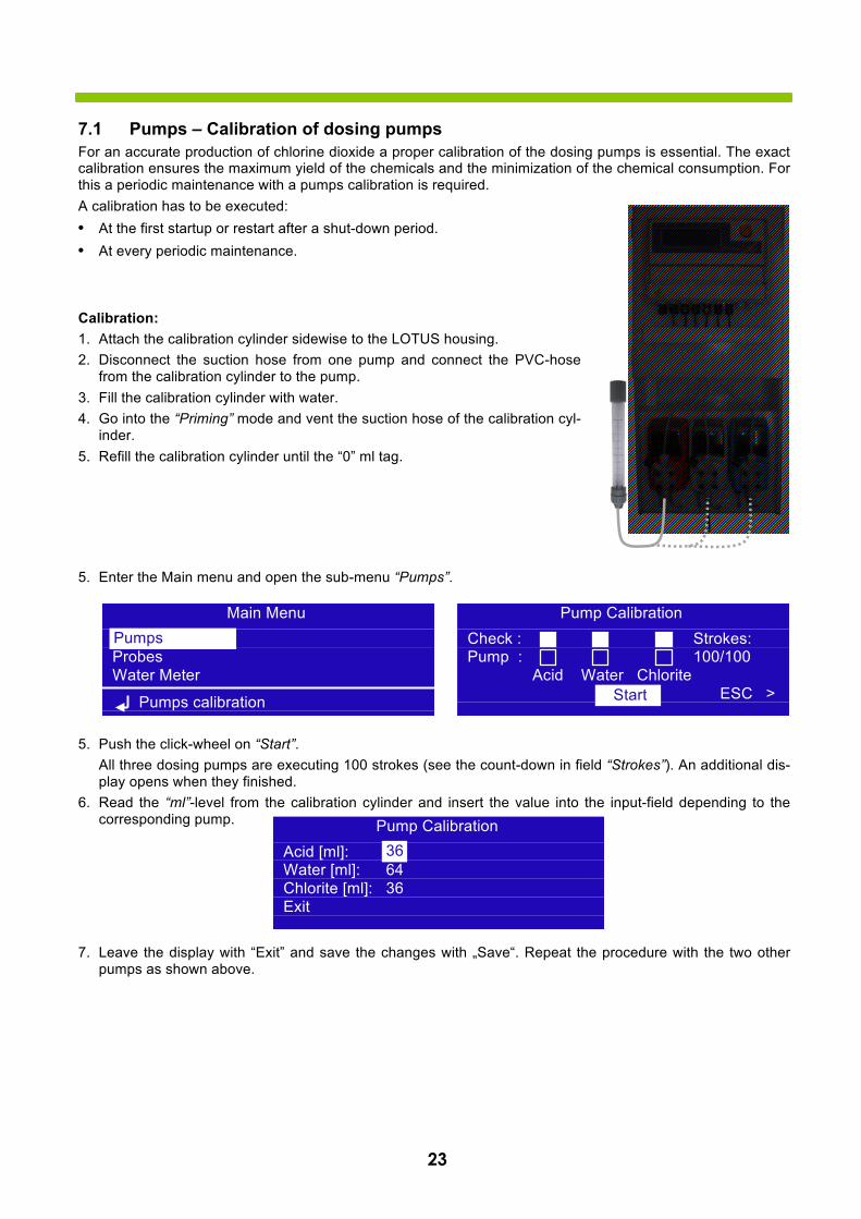
7.1 Pumps – Calibration of dosing pumps For an accurate production of chlorine dioxide a proper calibration of the dosing pumps is essential. The exact calibration ensures the maximum yield of the chemicals and the minimization of the chemical consumption. For this a periodic maintenance with a pumps calibration is required. A calibration has to be executed: • At the first startup or restart after a shut-down period.• At every periodic maintenance.
Calibration: 1. Attach the calibration cylinder sidewise to the LOTUS housing.2. Disconnect the suction hose from one pump and connect the PVC-hose
from the calibration cylinder to the pump.3. Fill the calibration cylinder with water.4. Go into the “Priming” mode and vent the suction hose of the calibration cyl-
inder.5. Refill the calibration cylinder until the “0” ml tag.
5. Enter the Main menu and open the sub-menu “Pumps”.
5. Push the click-wheel on “Start”.All three dosing pumps are executing 100 strokes (see the count-down in field “Strokes”). An additional dis-play opens when they finished.
6. Read the “ml”-level from the calibration cylinder and insert the value into the input-field depending to thecorresponding pump.
7. Leave the display with “Exit” and save the changes with „Save“. Repeat the procedure with the two otherpumps as shown above.
Main Menu Proportional Probes Water Meter
Pumps calibration
Pumps Pump Calibration
Check : Strokes: Pump : 100/100
Acid Water Chlorite ESC > Start
Pump Calibration Acid [ml]: 36 Water [ml]: 64 Chlorite [ml]: 36 Exit
36
24
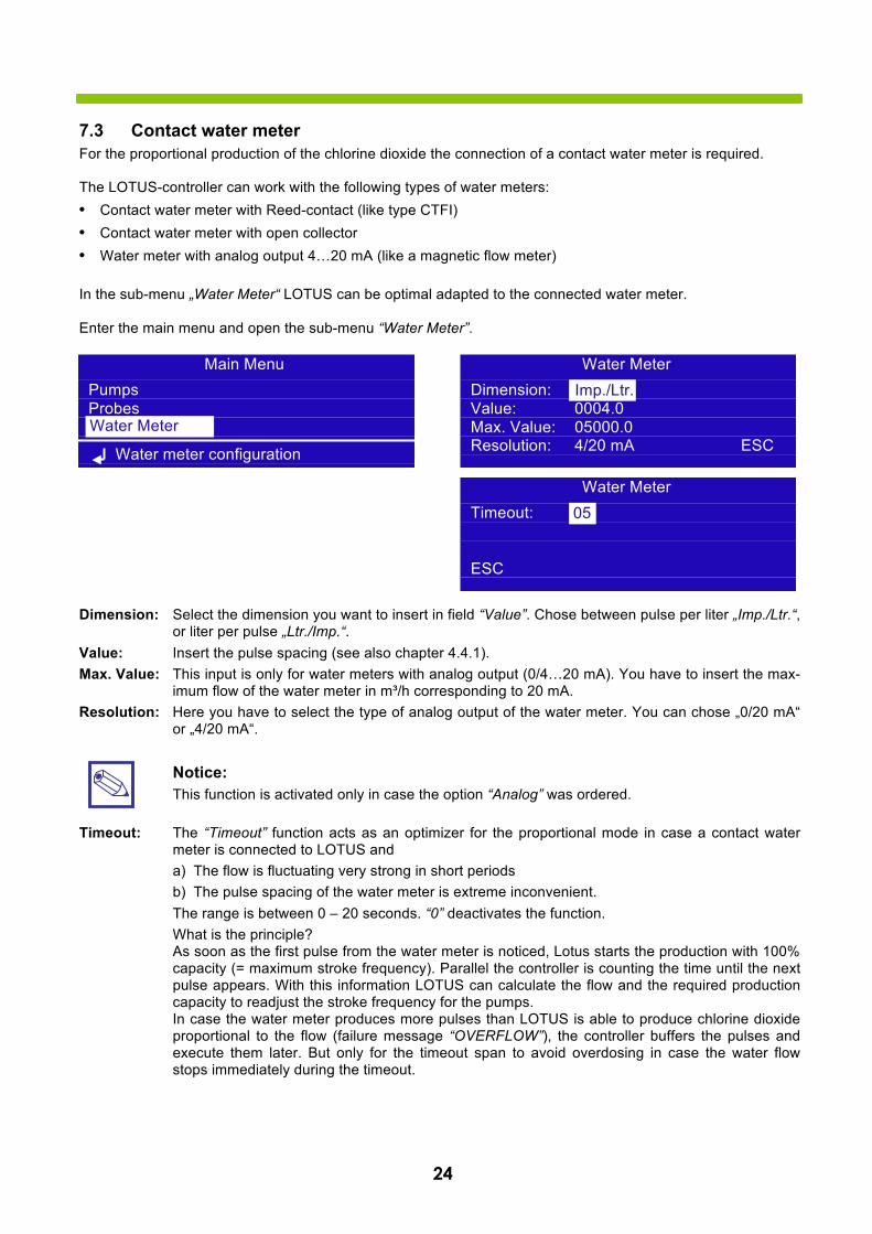
7.3 Contact water meter For the proportional production of the chlorine dioxide the connection of a contact water meter is required.
The LOTUS-controller can work with the following types of water meters: • Contact water meter with Reed-contact (like type CTFI)• Contact water meter with open collector• Water meter with analog output 4…20 mA (like a magnetic flow meter)
In the sub-menu „Water Meter“ LOTUS can be optimal adapted to the connected water meter.
Enter the main menu and open the sub-menu “Water Meter”.
Dimension: Select the dimension you want to insert in field “Value”. Chose between pulse per liter „Imp./Ltr.“, or liter per pulse „Ltr./Imp.“.
Value: Insert the pulse spacing (see also chapter 4.4.1). Max. Value: This input is only for water meters with analog output (0/4…20 mA). You have to insert the max-
imum flow of the water meter in m³/h corresponding to 20 mA. Resolution: Here you have to select the type of analog output of the water meter. You can chose „0/20 mA“
or „4/20 mA“.
Notice: This function is activated only in case the option “Analog” was ordered.
Timeout: The “Timeout” function acts as an optimizer for the proportional mode in case a contact water meter is connected to LOTUS and a) The flow is fluctuating very strong in short periodsb) The pulse spacing of the water meter is extreme inconvenient.The range is between 0 – 20 seconds. “0” deactivates the function. What is the principle? As soon as the first pulse from the water meter is noticed, Lotus starts the production with 100% capacity (= maximum stroke frequency). Parallel the controller is counting the time until the next pulse appears. With this information LOTUS can calculate the flow and the required production capacity to readjust the stroke frequency for the pumps. In case the water meter produces more pulses than LOTUS is able to produce chlorine dioxide proportional to the flow (failure message “OVERFLOW”), the controller buffers the pulses and execute them later. But only for the timeout span to avoid overdosing in case the water flow stops immediately during the timeout.
Water Meter Dimension: Imp/Ltr Value: 0004.0 Max. Value: 05000.0 Resolution: 4/20 mA ESC
Imp./Ltr.
Water Meter Timeout:
ESC
05
Main Menu Pumps Probes Water Meter
Water meter configuration
Water Meter
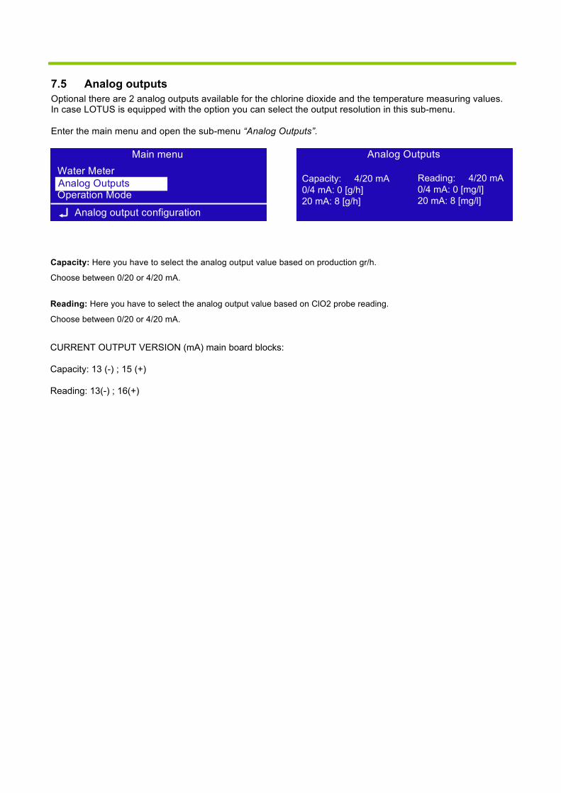
7.5 Analog outputs Optional there are 2 analog outputs available for the chlorine dioxide and the temperature measuring values. In case LOTUS is equipped with the option you can select the output resolution in this sub-menu.
Enter the main menu and open the sub-menu “Analog Outputs”.
Capacity: Here you have to select the analog output value based on production gr/h.
Choose between 0/20 or 4/20 mA.
Main menu Water Meter Analog-Ausgänge Operation Mode
Analog output configuration
Analog Outputs
Analog Outputs
Capacity: 4/20 mA 0/4 mA: 0 [g/h]20 mA: 8 [g/h]
Reading: 4/20 mA 0/4 mA: 0 [mg/l]20 mA: 8 [mg/l]
Reading: Here you have to select the analog output value based on ClO2 probe reading.
Choose between 0/20 or 4/20 mA.
CURRENT OUTPUT VERSION (mA) main board blocks:
Capacity: 13 (-) ; 15 (+)
Reading: 13(-) ; 16(+)
26
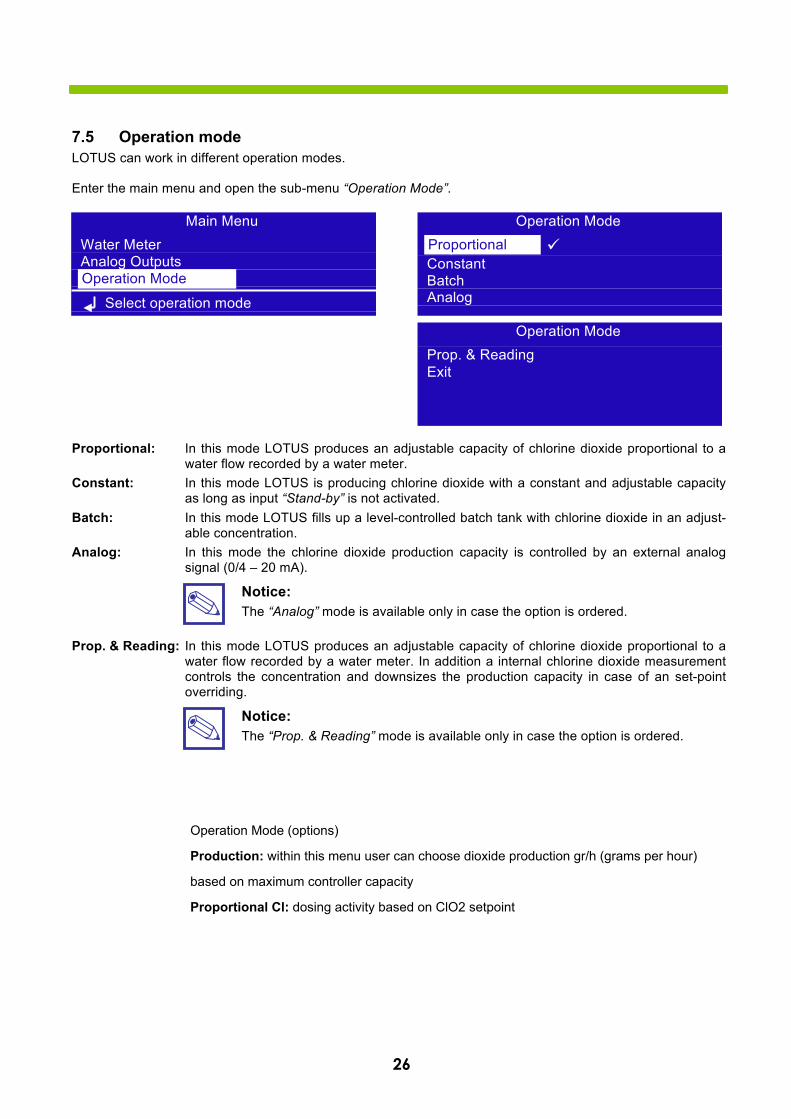
7.5 Operation mode LOTUS can work in different operation modes.
Enter the main menu and open the sub-menu “Operation Mode”.
Proportional: In this mode LOTUS produces an adjustable capacity of chlorine dioxide proportional to a water flow recorded by a water meter.
Constant: In this mode LOTUS is producing chlorine dioxide with a constant and adjustable capacity as long as input “Stand-by” is not activated.
Batch: In this mode LOTUS fills up a level-controlled batch tank with chlorine dioxide in an adjust-able concentration.
Analog: In this mode the chlorine dioxide production capacity is controlled by an external analog signal (0/4 – 20 mA).
Notice: The “Analog” mode is available only in case the option is ordered.
Prop. & Reading: In this mode LOTUS produces an adjustable capacity of chlorine dioxide proportional to a water flow recorded by a water meter. In addition a internal chlorine dioxide measurement controls the concentration and downsizes the production capacity in case of an set-point overriding.
Notice: The “Prop. & Reading” mode is available only in case the option is ordered.
Main Menu Water Meter Analog Outputs Betriebsmodus
Select operation mode
Operation Mode
Operation Mode
Proportional ü Constant Batch Analog
Proportional
Operation Mode Prop. & Reading Exit
Operation Mode (options)
Production: within this menu user can choose dioxide production gr/h (grams per hour)
based on maximum controller capacity
Proportional Cl: dosing activity based on ClO2 setpoint
27
7.5.1 Proportional mode In the proportional mode LOTUS produces an adjustable capacity of chlorine dioxide proportional to a water flow recorded by a water meter.
Prod. Capacity: Here you can adjust the requested chlorine dioxide concentration.
Warning: • The controller takes the inserted value in “Prod. Capacity” for the calculation of the required stroke
frequency of the dosing pumps for the production of chlorine dioxide proportional to the flow. This means that it is a theoretically value and not the real concentration in the water!
• The operator is responsible by its own for the proper adjustment of this control-value!
• The operator has to countercheck the chlorine dioxide concentration in the connected water systemwith a suitable photometer to verify the real concentration and to readjust the “Prod. Capacity” untilthe required concentration is stable achieved.
General Notices: Theoretically it is possible to adjust the production capacity up to 9.99 mg/l. But for very low water flows, resp. water consumption it can be dangerous to do this and should be absolutely avoided! In case the water flow exceeds the maximum production capacity a proportional production is not longer possible. In the following table you can find the maximum water flow corresponding to the maximum production capacity:
LOTUS 8 20 Production capacity
[mg/l] Water flow
[m³/h] 0,10 80 200 0,20 40 100 0,30 26.6 66.6 0,40 20 50 0,50 16 40 0,60 13.3 33.3 0,70 11.4 28.5 0,80 10 25 0,90 8.8 22.2 1,00 8 20
The overriding of the maximum possible production capacity caused by the water flow is shown on the display with a special blinking message “Overflow”:
As soon as the water flow drops down under the maximum acceptable value, the message disappears.
Proportional Mode Prod. Capacity: 0.15 mg/l Mode:
Proportional
ESC
Operation Mode
Proportional ü Constant Batch Analog
Proportional
02-12-10 EMEC 09:10:55 LOTUS 25.9° C
Chlorine Dioxide Generator Overflow
Status Menu Logbook Help
28
7.5.2 Constant mode In this mode LOTUS is producing chlorine dioxide with a constant and adjustable capacity as long as input “Stand-by” is not activated. Two different capacities can be adjusted depending to the digital inputs “Batch tank empty” [terminal 34 and 35] and “Stand-by” [terminal 44 and 45].
Capacity 1: In this field you can adjust the production capacity for the digital input “Batch tank empty”. Capacity 2: In this field you can adjust the production capacity for the digital input “Stand-by”.
Situation STAND-BY (44, 45) BATCH TANK EMPTY (34, 35)
LOTUS “STAND-BY”
Capacity 1
Capacity 2
7.5.3 Analog mode In this mode the chlorine dioxide production capacity is controlled by an external analog signal (0/4 – 20 mA).
Capacity at 20 mA: Here you adjust the maximum production capacity for a 20 mA input signal.
Notice: Independent to the selected operation mode LOTUS stops as soon as the digital input “Stand-by” appears!
Notice: The “Analog” mode is available only in case the option is ordered.
Constant Mode Capacity 1: 50 % Capacity 2: 100 %
ESC
Operation Mode Proportional Konstant ü Batch Analog
Constant
Analog Mode Capacity at 20 mA: 100 %
ESC
Operation Mode Proportional Constant Batch Analog üAnalog
29
7.5.4 Batch mode In this mode LOTUS fills up a level-controlled batch tank with chlorine dioxide in an adjustable concentration. The two digital inputs “Batch tank empty” [terminal 34 and 35] and “Stand-by” [terminal 44 and 45] are used for the level-control.
Situation Step Terminal 34, 35
Level tank empty
Terminal 44, 45
Level tank full
Tank empty 1
Level is rising 2
Tank full 3
Level falls down 4
Tank empty 1
Step 1: Step 2:
Step 3: Step 4:
In case one of the level-switch failed or the cable is damaged a failure message appears: Failure Level-switch:
Operation Mode Proportional Constant Batch ü Analog Batch
Status Level Tank full : Mode: Level Tank empty : Batch
Filling Batch Tank < ESC >
Status Level Tank full : Mode: Level Tank empty : Batch
Start Filling Batch Tank < ESC >
Status Level Tank full : Mode: Level Tank empty : Batch
Batch Tank full < ESC >
Status Level Tank full : Mode: Level Tank empty : Batch
Draining Batch Tank < ESC >
Status Level Tank full : Mode: Level Tank empty : Batch
Failure Level-Switch < ESC >
02-12-10 EMEC 09:10:55 LOTUS 25.9° C
Chlorine Dioxide Generator Failure Level-Switch
Status Menu Logbook Help Status
30
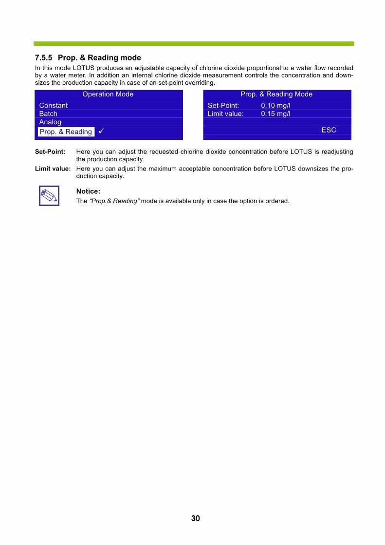
7.5.5 Prop. & Reading mode In this mode LOTUS produces an adjustable capacity of chlorine dioxide proportional to a water flow recorded by a water meter. In addition an internal chlorine dioxide measurement controls the concentration and down-sizes the production capacity in case of an set-point overriding.
Set-Point: Here you can adjust the requested chlorine dioxide concentration before LOTUS is readjusting the production capacity.
Limit value: Here you can adjust the maximum acceptable concentration before LOTUS downsizes the pro-duction capacity.
Notice: The “Prop.& Reading” mode is available only in case the option is ordered.
Operation Mode Constant Batch Analog
ü Prop. & Reading
Prop. & Reading Mode Set-Point: 0.10 mg/l Limit value: 0.15 mg/l
ESC
31
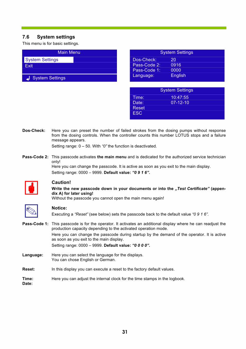
7.6 System settings This menu is for basic settings.
Dos-Check: Here you can preset the number of failed strokes from the dosing pumps without response from the dosing controls. When the controller counts this number LOTUS stops and a failure message appears. Setting range: 0 – 50. With “0” the function is deactivated.
Pass-Code 2: This passcode activates the main menu and is dedicated for the authorized service technician only! Here you can change the passcode. It is active as soon as you exit to the main display. Setting range: 0000 – 9999. Default value: “0 9 1 6”.
Caution! Write the new passcode down in your documents or into the „Test Certificate” (appen-dix A) for later using! Without the passcode you cannot open the main menu again!
Notice: Executing a “Reset” (see below) sets the passcode back to the default value “0 9 1 6”.
Pass-Code 1: This passcode is for the operator. It activates an additional display where he can readjust the production capacity depending to the activated operation mode. Here you can change the passcode during startup by the demand of the operator. It is active as soon as you exit to the main display. Setting range: 0000 – 9999. Default value: “0 0 0 0”.
Language: Here you can select the language for the displays. You can chose English or German.
Reset: In this display you can execute a reset to the factory default values.
Time: Here you can adjust the internal clock for the time stamps in the logbook. Date:
Main Menu Proportional Exit
System Settings
System Settings System Settings
Dos-Check: 20 Pass-Code 2: 0916 Pass-Code 1: 0000 Language: English
System Settings Time: 10:47:55 Date: 07-12-10Reset ESC

Connections to the mainboardBefore performing any operation on the Block board of the instrument, it is mandatory to disconnect it from the mains. To facilitate the connections to the mainboard, it has been divided into two blocks: electrical connections and I/O con-nections.
Electrical connections:
F1: Main fuse (6.3AT)F2: Instrument fuse (3.15AT)
MAIN POWER SUPPLY (115VAC / 240VAC): L(Phase), E(Earth), N(Neutral)
SET-POINT OUTPUTS (115VAC TO 240VAC): (free contact outputs are not protected with a fuse and isolation between the outputs and the power supply is 250V MAX):
5 - E - N (F2 Fuse-protected) Alarm Out
GENERAL ALARM OUTPUT:
10(N.C.), 11(C), 12(N .O.)
] ]Electrical Connections I/O Connections
Blocks numbering is relative to the area on which you are working!Danger
Unplug power cable from main
power supply before operate
L 1 2 3 4 5 6
E E E E E E E
N N N N N N N 7 8 9 10 11 12F1
F2
A B 1 2 3 4 5 6 7 8 9 10 11 12 13 14 15 16 17 18 19 20 21 22 23 24 25 26 27 28
29 30 31 32 33 34 35 36 37 38 39 40 41 42 43 44 45 46 47 48 49 50 51 52 53 54 55 56
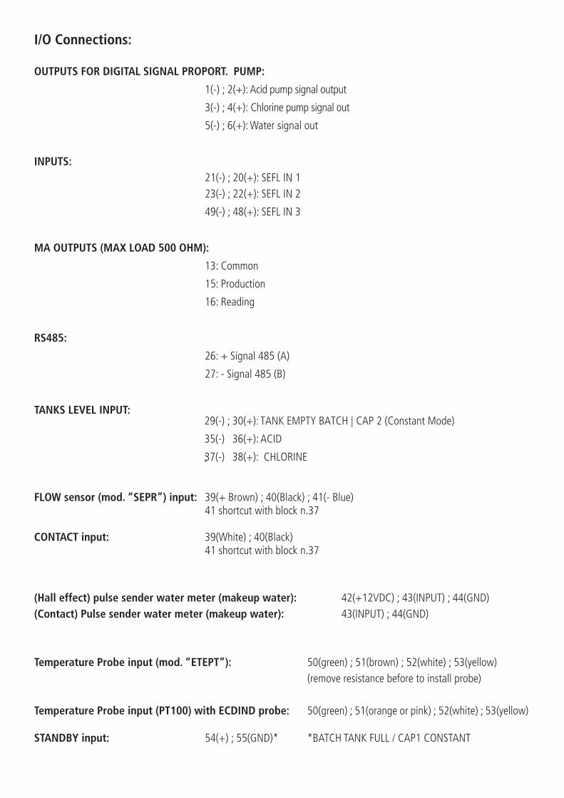
I/O Connections:
OUTPUTS FOR DIGITAL SIGNAL PROPORT. PUMP:
1(-) ; 2( + ): Acid pump signal output
3(-) ; 4( + ): Chlorine pump signal out
;5(-) 6(+): W ater signal out
INPUTS:21(-) ; 20(+): SEFL IN 123(-) ; 22(+): SEFL IN 2
49(-) ; 48(+): SEFL IN 3
MA OUTPUTS (MAX LOAD 500 OHM):
RS485:
TANKS LEVEL INPUT:
FLOW sensor (mod. “SEPR”) input: 39(+ Brown) ; 40(Black) ; 41(- Blue)
CONTACT input:
41 shortcut with block n.37
39(White) ; 40(Black)41 shortcut with block n.37
(Hall effect) pulse sender water meter (makeup water): (Contact) Pulse sender water meter (makeup water):
42(+12VDC) ; 43(INPUT) ; 44(GND) 43(INPUT) ; 44(GND)
Temperature Probe input (mod. “ETEPT”): 50(green) ; 51(brown) ; 52(white) ; 53(yellow)(remove resistance before to install probe)
50(green) ; 51(orange or pink) ; 52(white) ; 53(yellow)Temperature Probe input (PT100) with ECDIND probe:
STANDBY input: 54(+) ; 55(GND)* *BATCH TANK FULL / CAP1 CONSTANT
13: Common
15: Production
16: Reading
26: + Signal 485 (A)
27: - Signal 485 (B)
29(-) ; 30(+): TANK EMPTY BATCH | CAP 2 (Constant Mode)
35(-) 36(+): ACID
;37(-) 38(+): CHLORINE
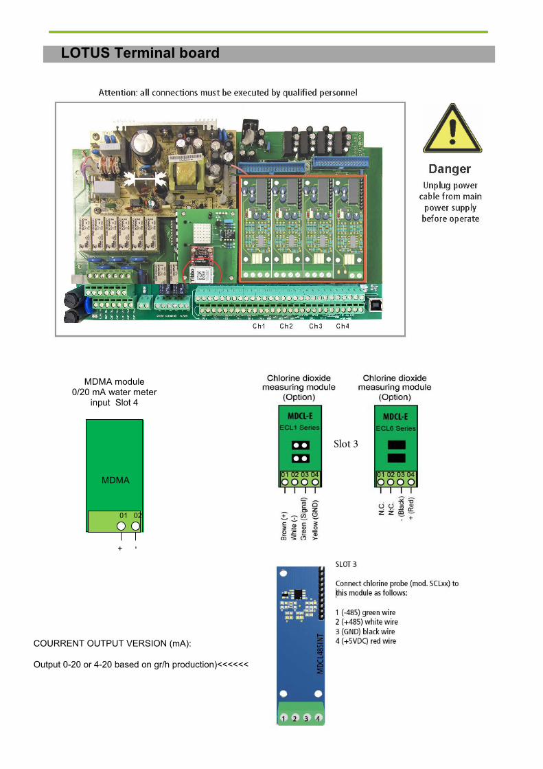
LOTUS Terminal board
MDMA module 0/20 mA water meter
input Slot 4
+ -
MDMA
01 02
Slot 3
COURRENT OUTPUT VERSION (mA):
Output 0-20 or 4-20 based on gr/h production)<<<<<<

ADDENDUM DIOXIDE PROBE SAFETY SYSTEM
Dioxide Probe
Use this function to setup sensor that detects dioxide into air. This option is useful during a plant’s dioxide leakage to prevent dangerous high dioxide concentration. To set this valure refer to the sensor sensitiveness as printed on head’s label (see below picture). Do not edit this function if not otherwise specified or if unsure of value to enter.
Other options are: MAIN MENU: HIDE to not show a warning message. Use exclusively if no sensor is connected.MAIN MENU: SHOW to enable warning message and related alarm on main screen. Enabled by default.
Attention: this procedure assumes that the instrument is configured properly and connected to a working sensor, otherwise the results may not be reliable.
Dioxide into air alarm
Use this menu to set a maximum dioxide into air concentration value into environment. Don’t change this value if unsure of value to enter. Do not edit this function if not otherwise specified.
Dioxide into air main sensor head
Connection:
Block 1 : (+12VDC) BrownBlock 2 : (-12VDC) WhiteBlock 3 : (V-out) Green Block 4 : (GND) Yellow
DIOXIDE SENSOR MODULESlot 2
1 2 3 4

33
10. Technical Data
LOTUS MNI 8 LOTUS MINI 20 ClO2 production capacity g/h 8 20 Maximum operation pressure bar 10 10 Chemical consumption at max. production l/h each 0.2 each 0.5 Concentration of ClO2 stock solution g/l approx. 2 - 20 Power supply 90 – 265 V, 50/60 Hz Energy consumption w/h 50 Protection class IP 65 Dimension: Width mm 450 Height mm 1080 Depth mm 360 Transportation weight kg approx. 30
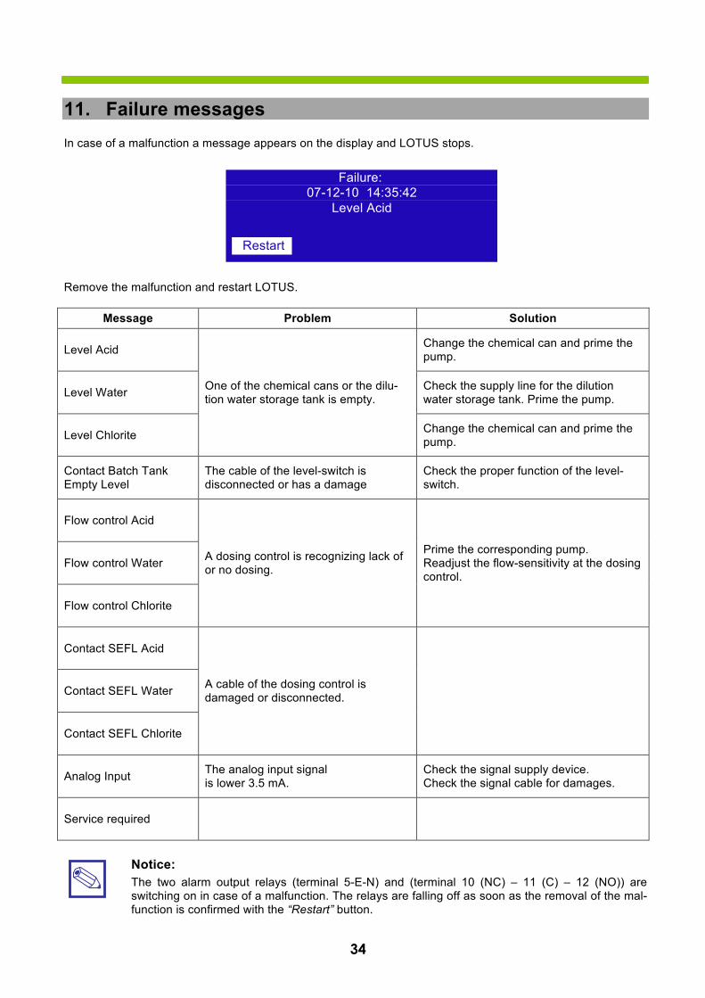
34
11. Failure messagesIn case of a malfunction a message appears on the display and LOTUS stops.
Remove the malfunction and restart LOTUS.
Message Problem Solution
Level Acid
One of the chemical cans or the dilu-tion water storage tank is empty.
Change the chemical can and prime the pump.
Level Water Check the supply line for the dilution water storage tank. Prime the pump.
Level Chlorite Change the chemical can and prime the pump.
Contact Batch Tank Empty Level
The cable of the level-switch is disconnected or has a damage
Check the proper function of the level-switch.
Flow control Acid
A dosing control is recognizing lack of or no dosing.
Prime the corresponding pump. Readjust the flow-sensitivity at the dosing control.
Flow control Water
Flow control Chlorite
Contact SEFL Acid
A cable of the dosing control is damaged or disconnected. Contact SEFL Water
Contact SEFL Chlorite
Analog Input The analog input signal is lower 3.5 mA.
Check the signal supply device. Check the signal cable for damages.
Service required
Notice: The two alarm output relays (terminal 5-E-N) and (terminal 10 (NC) – 11 (C) – 12 (NO)) are switching on in case of a malfunction. The relays are falling off as soon as the removal of the mal-function is confirmed with the “Restart” button.
Failure: 07-12-10 14:35:42
Level Acid
Restart


R3-10-14 37