Instruction manual series 880 CIU Prime - Honeywell€¦ · Instruction manual 880 CIU Prime Page 1...
36
Instruction manual 880 CIU Prime Page 1 Instruction manual series 880 CIU Prime May 2009 Part no.: 4416525 Revision 4 Enraf B.V. P.O. Box 812 2600 AV Delft Netherlands Tel. : +31 15 2701 100 Fax : +31 15 2701 111 E-mail : [email protected] Website : http://www.honeywell.com/ps
Transcript of Instruction manual series 880 CIU Prime - Honeywell€¦ · Instruction manual 880 CIU Prime Page 1...
Instruction manual 880 CIU Prime Page 1
Instruction manual series 880 CIU Prime
May 2009
Part no.: 4416525
Revision 4
Enraf B.V.
P.O. Box 812
2600 AV Delft
Netherlands
Tel. : +31 15 2701 100
Fax : +31 15 2701 111
E-mail : [email protected]
Website : http://www.honeywell.com/ps
Page 2 Instruction manual 880 CIU Prime
Copyright 2000 - 2009 Enraf BV All rights reserved.
Reproduction in any form without the prior consent of Enraf BV is not allowed.
This instruction manual is for information only. The contents, descriptions and specifications are
subject to change without notice. Enraf BV accepts no responsibility for any errors that may appear
in this instruction manual.
The warranty terms and conditions for Honeywell Enraf products applicable in the country of
purchase are available from your supplier. Please retain them with your proof of purchase.
Preface
Instruction manual 880 CIU Prime Page 3
Preface This manual has been written for the technicians involved with the
communication with the Honeywell Enraf series 880 CIU Prime via
ModbusTM
.
For installation and commissioning of the CIU Prime, please refer to
the related installation guide and instruction manual Ensite Pro.
This manual describes the communication between a CIU Prime and
higher layered systems. The communication is based on emulation of
the ModbusTM
protocol (Gould Modicon Modbus Protocol Reference
Guide, PI-MBUS-300, Rev. B).
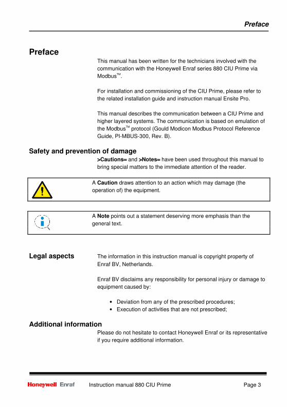
Safety and prevention of damage
>>>>Cautions==== and >>>>Notes==== have been used throughout this manual to
bring special matters to the immediate attention of the reader.
Legal aspects The information in this instruction manual is copyright property of
Enraf BV, Netherlands.
Enraf BV disclaims any responsibility for personal injury or damage to
equipment caused by:
• Deviation from any of the prescribed procedures;
• Execution of activities that are not prescribed;
Additional information
Please do not hesitate to contact Honeywell Enraf or its representative
if you require additional information.
A Caution draws attention to an action which may damage (the
operation of) the equipment.
A Note points out a statement deserving more emphasis than the
general text.
Table of contents
Page 4 Instruction manual 880 CIU Prime
Table of Contents
Preface .............................................................................................................................................. 3
Introduction........................................................................................................................................ 5
Safety ................................................................................................................................................ 7
Safety aspects of the CIU Prime................................................................................................ 7
Personal safety .......................................................................................................................... 7
Safety conventions .................................................................................................................... 8
Description and operation ................................................................................................................. 9
Description................................................................................................................................. 9
Operation................................................................................................................................. 10
Default communication settings............................................................................................... 10
Commissioning................................................................................................................................ 11
Read data........................................................................................................................................ 12
Write data ........................................................................................................................................ 15
CIU data................................................................................................................................... 15
Gauge commands ................................................................................................................... 15
Dimensions...................................................................................................................................... 16
Statuses of data....................................................................................................................... 17
Validity byte ............................................................................................................................. 17
Status byte............................................................................................................................... 18
Modbus number representation ...................................................................................................... 19
Scaling and offset .................................................................................................................... 21
Maintenance / trouble shooting ....................................................................................................... 23
Appendix A Glossary .......................................................................................................... 24
Appendix B Article and part numbers ................................................................................. 29
Appendix C Related documents ......................................................................................... 30
Introduction
Instruction manual 880 CIU Prime Page 5
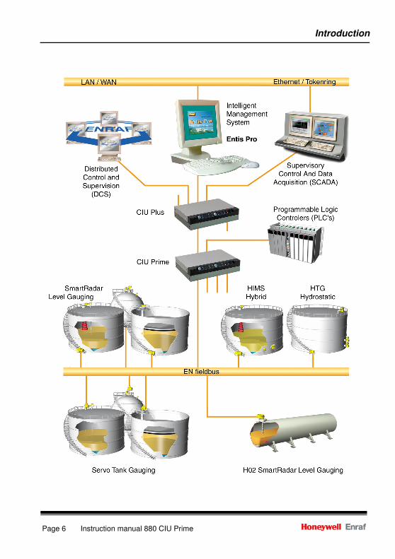
Introduction The configuration of the new tank inventory system consists of
modular parts:
• Entis Pro
• CIU Plus
• CIU Prime
• field instrumentation
Entis Pro This system displays calculated data from the CIU Plus. It is a
Windows7NT based program, displaying data in windows, boxes,
tables, graphs, etc.
CIU Plus This unit calculates volume and mass. It requests input data from the
CIU Prime and calculates all other data. It presents data to higher
layered systems like Entis Pro, SCADA, DCS, ENSITE, etc.
CIU Prime This unit is an interface between the field instrumentation (e.g. 854
ATG, 873 SmartRadar, etc.) and inventory systems (CIU Plus, PLC,
ENSITE, etc.).
Host ports Two fixed RS-232C/RS485 host ports interface to a CIU Plus, PLC,
ENSITE, etc.
Field ports Up to four field ports can be installed to interface the Honeywell Enraf
field bus (BPM Bi-Phase Mark). By changing one or more field ports
by an
RS-232C/RS485 field port, the CIU Prime can interface the 858 CIU
(Communications Interface Unit).
Automatic polling After configuration, the CIU Prime automatically performs the polling of
the connected gauges and stores the information in a database. For a
description of the configuration and programming, refer to the
instruction manual Ensite Pro.
Field instrumentation
The instruments in the field collect data such as level, temperature,
density and/or pressure. The instruments are based on several
principles: mechanical, servo, radar, hydrostatic and capacitive or a
combination. The instruments measure the data and transmit it upon
request of higher layered systems.
Introduction
Page 6 Instruction manual 880 CIU Prime
Safety
Instruction manual 880 CIU Prime Page 7
Safety
Safety aspects of the CIU Prime
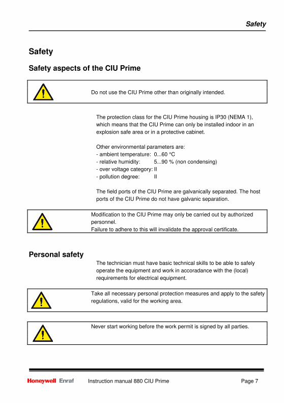
The protection class for the CIU Prime housing is IP30 (NEMA 1),
which means that the CIU Prime can only be installed indoor in an
explosion safe area or in a protective cabinet.
Other environmental parameters are:
- ambient temperature: 0...60 °C
- relative humidity: 5...90 % (non condensing)
- over voltage category: II
- pollution degree: II
The field ports of the CIU Prime are galvanically separated. The host
ports of the CIU Prime do not have galvanic separation.
Personal safety The technician must have basic technical skills to be able to safely
operate the equipment and work in accoradance with the (local)
requirements for electrical equipment.
Do not use the CIU Prime other than originally intended.
Modification to the CIU Prime may only be carried out by authorized
personnel.
Failure to adhere to this will invalidate the approval certificate.
Take all necessary personal protection measures and apply to the safety
regulations, valid for the working area.
Never start working before the work permit is signed by all parties.
Safety
Page 8 Instruction manual 880 CIU Prime
Safety conventions >>>>Cautions==== and >>>>Notes==== have been used throughout this manual to
bring special matters to the immediate attention of the reader.
A Caution draws attention to an action which may damage (the
operation of) the equipment.
A Note points out a statement deserving more emphasis than the
general text.
Description and operation
Instruction manual 880 CIU Prime Page 9
Description and operation
Description The CIU Prime consists of the following parts:
- Front panel
- Rear connectors
- Internal circuitry
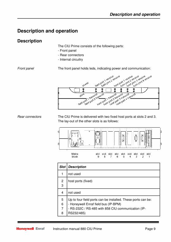
Front panel The front panel holds leds, indicating power and communication:
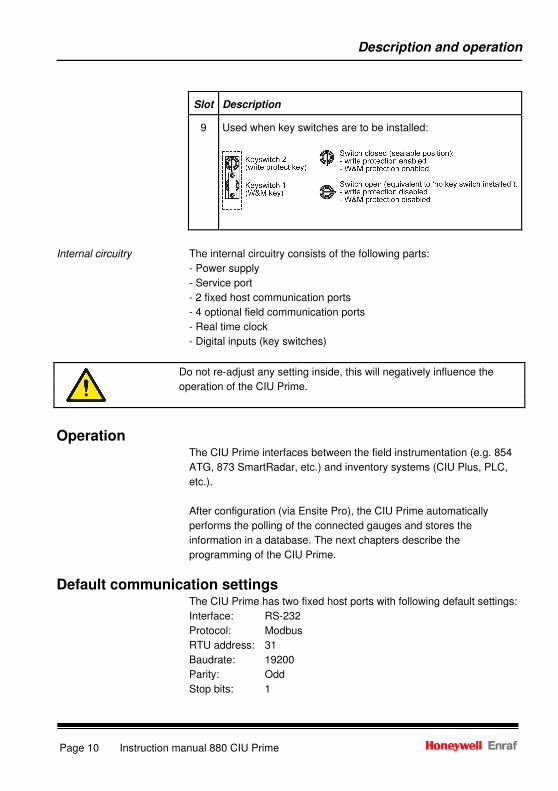
Rear connectors The CIU Prime is delivered with two fixed host ports at slots 2 and 3.
The lay-out of the other slots is as follows:
Slot
Description
1
not used
2
3
host ports (fixed)
4
not used
5
6
7
8
Up to four field ports can be installed. These ports can be:
- Honeywell Enraf field bus (IP-BPM)
- RS-232C / RS-485 with 858 CIU communication (IP-
RS232/485)
Description and operation
Page 10 Instruction manual 880 CIU Prime
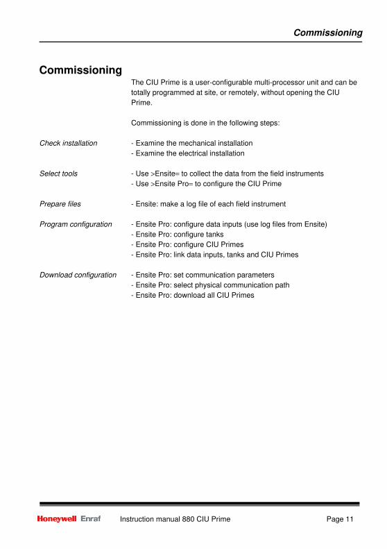
Slot
Description
9
Used when key switches are to be installed:
Internal circuitry The internal circuitry consists of the following parts:
- Power supply
- Service port
- 2 fixed host communication ports
- 4 optional field communication ports
- Real time clock
- Digital inputs (key switches)
Operation The CIU Prime interfaces between the field instrumentation (e.g. 854
ATG, 873 SmartRadar, etc.) and inventory systems (CIU Plus, PLC,
etc.).
After configuration (via Ensite Pro), the CIU Prime automatically
performs the polling of the connected gauges and stores the
information in a database. The next chapters describe the
programming of the CIU Prime.
Default communication settings The CIU Prime has two fixed host ports with following default settings:
Interface: RS-232
Protocol: Modbus
RTU address: 31
Baudrate: 19200
Parity: Odd
Stop bits: 1
Do not re-adjust any setting inside, this will negatively influence the
operation of the CIU Prime.
Commissioning
Instruction manual 880 CIU Prime Page 11
Commissioning The CIU Prime is a user-configurable multi-processor unit and can be
totally programmed at site, or remotely, without opening the CIU
Prime.
Commissioning is done in the following steps:
Check installation - Examine the mechanical installation
- Examine the electrical installation
Select tools - Use >Ensite= to collect the data from the field instruments
- Use >Ensite Pro= to configure the CIU Prime
Prepare files - Ensite: make a log file of each field instrument
Program configuration - Ensite Pro: configure data inputs (use log files from Ensite)
- Ensite Pro: configure tanks
- Ensite Pro: configure CIU Primes
- Ensite Pro: link data inputs, tanks and CIU Primes
Download configuration - Ensite Pro: set communication parameters
- Ensite Pro: select physical communication path
- Ensite Pro: download all CIU Primes
Read data
Page 12 Instruction manual 880 CIU Prime
Read data Data can be read from the CIU Prime via holding- or input-registers.
Statusses can be read via discrete inputs, holding- or input-registers.
Data can be read via holding registers and input registers.
See manual ´Instruction manual ModbusTM
Protocol´ chapter
Honeywell Enraf implementation.
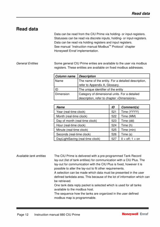
General Entities Some general CIU Prime enties are available to the user via modbus
registers. These entities are available on fixed modbus addresses.
Column name Description
Name The name of the entity. For a detailed description,
refer to Appendix A, Glossary.
ID The unique identifier of the entity
Dimension Category of dimensional units. For a detailed
description, refer to chapter >Dimensions=.
Name ID Comment(s)
Year (real-time clock) 521 Time (YYYY)
Month (real-time clock) 522 Time (MM)
Day of month (real-time clock) 523 Time (dd)
Hour (real-time clock) 524 Time (h)
Minute (real-time clock) 525 Time (min)
Seconds (real-time clock) 526 Time (s)
DayLightSaving (real-time clock) 527 0 = off; 1 = on
Available tank entities The CIU Prime is delivered with a pre-programmed Tank Record
lay-out (list of tank entities) for communication with a CIU Plus. The
lay-out for communication with the CIU Plus is fixed, however it is
possible to alter the lay-out to fit other requirements.
A selection can be made which data must be presented in the user
defined tankdata area. This because of the lot of information which can
be retrieved.
One tank data reply packet is selected which is used for all tanks
available to the modbus host.
The sequence how the tanks are organized in the user defined
modbus map is programmable.
Read data
Instruction manual 880 CIU Prime Page 13
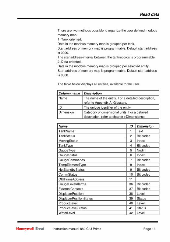
There are two methods possible to organize the user defined modbus
memory map:
1. Tank oriented.
Data in the modbus memory map is grouped per tank.
Start address of memory map is programmable. Default start address
is 0000.
The startaddress-interval between the tankrecords is programmable.
2. Data oriented.
Data in the modbus memory map is grouped per selected entity.
Start address of memory map is programmable. Default start address
is 0000.
The table below displays all entities, available to the user.
Column name Description
Name The name of the entity. For a detailed description,
refer to Appendix A, Glossary.
ID The unique identifier of the entity
Dimension Category of dimensional units. For a detailed
description, refer to chapter >Dimensions=.
Name ID Dimension
TankName 1 Text
TankStatus 2 Bit coded
MovingStatus 3 Index
TankType 4 Bit coded
GaugeType 5 Nodim
GaugeStatus 6 Index
GaugeCommands 7 Bit coded
TempElementType 8 Index
HotStandbyStatus 9 Bit coded
CommStatus 10 Bit coded
CIUPrimeAddress 11
GaugeLevelAlarms 36 Bit coded
ExternalContacts 37 Bit coded
DisplacerPosition 38 Level
DisplacerPositionStatus 39 Status
ProductLevel 40 Level
ProductLevelStatus 41 Status
WaterLevel 42 Level
Read data
Page 14 Instruction manual 880 CIU Prime
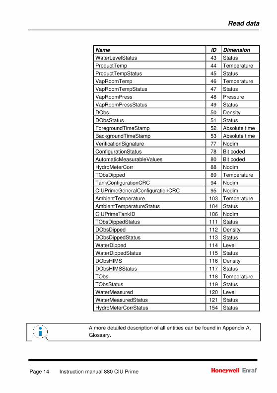
Name ID Dimension
WaterLevelStatus 43 Status
ProductTemp 44 Temperature
ProductTempStatus 45 Status
VapRoomTemp 46 Temperature
VapRoomTempStatus 47 Status
VapRoomPress 48 Pressure
VapRoomPressStatus 49 Status
DObs 50 Density
DObsStatus 51 Status
ForegroundTimeStamp 52 Absolute time
BackgroundTimeStamp 53 Absolute time
VerificationSignature 77 Nodim
ConfigurationStatus 78 Bit coded
AutomaticMeasurableValues 80 Bit coded
HydroMeterCorr 88 Nodim
TObsDipped 89 Temperature
TankConfigurationCRC 94 Nodim
CIUPrimeGeneralConfigurationCRC 95 Nodim
AmbientTemperature 103 Temperature
AmbientTemperatureStatus 104 Status
CIUPrimeTankID 106 Nodim
TObsDippedStatus 111 Status
DObsDipped 112 Density
DObsDippedStatus 113 Status
WaterDipped 114 Level
WaterDippedStatus 115 Status
DObsHIMS 116 Density
DObsHIMSStatus 117 Status
TObs 118 Temperature
TObsStatus 119 Status
WaterMeasured 120 Level
WaterMeasuredStatus 121 Status
HydroMeterCorrStatus 154 Status
A more detailed description of all entities can be found in Appendix A,
Glossary.
Write data
Instruction manual 880 CIU Prime Page 15
Write data Please refer to the =Instruction manual Modbus
TM Protocol= chapter
Honeywell Enraf implementation
CIU data The internal date and time can be overwritten by writing holding
registers.
Gauge commands Gauge commands can be issued with the >Force single coil=
command.
Dimensions
Page 16 Instruction manual 880 CIU Prime
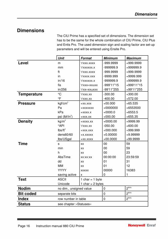
Dimensions The CIU Prime has a specified set of dimensions. The dimension set
has to be the same for the whole combination of CIU Prime, CIU Plus
and Entis Pro. The used dimension sign and scaling factor are set-up
parameters and will be entered using Ensite Pro.
Unit Format Minimum Maximum
Level m
mm
ft
in
in/16
fis
in/256
∀xxx.xxxx
∀xxxxxx.x
∀xxx.xxxx
∀xxxx.xxx
∀xxxxxx.x
∀xxx=xx≅xx
∀xx=xx≅xxx
-999.9999
-999999.9
-999.9999
-9999.999
-999999.9
-999'11"15
-99'11"255
+999.9999
+999999.9
+999.9999
+9999.999
+999999.9
+999'11"15
+99'11"255
Temperature °C
°F
∀xxx.xx
∀xxx.xx
-300.00
-400.00
+300.00
+572.00
Pressure kgf/cm2
Pa
kPa
psi (lbf/in2)
+xx.xxx
+xxxxxxx
+xxxx.x
+xxx.xx
+00.000
+0000000
+0000.0
+000.00
+65.535
+6553500
+6553.5
+655.35
Density kg/m3
°API
lbs/ft3
dens60/60
lbs/USgal
+xxxx.xx
∀xxx.xx
+xxx.xxx
+x.xxxxx
+xx.xxxx
+0000.00
-050.00
+000.000
+0.00000
+00.0000
+9999.99
+600.00
+999.999
+9.99999
+99.9999
Time s
min
h
AbsTime
dd
MM
YYYY
saving active
xx
xx
xx
xx:xx:xx
xx
xx
xxxxx
x
00
00
00
00:00:00
01
01
00000
0
59
59
23
23:59:59
31
12
16383
1
Text ASCII
Unicode
1 char = 1 byte
1 char = 2 bytes
Nodim no dim., unsigned value 0 2#bits
Bit coded separate bits 0 2#bits
Index row number in table 0 2#bits
Status see chapter >Statuses=
Dimensions
Instruction manual 880 CIU Prime Page 17
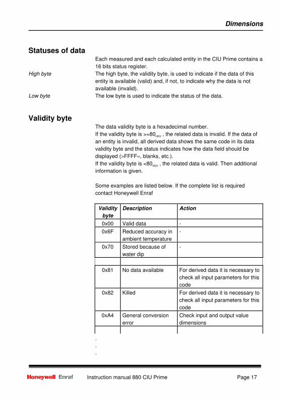
Statuses of data Each measured and each calculated entity in the CIU Prime contains a
16 bits status register.
High byte The high byte, the validity byte, is used to indicate if the data of this
entity is available (valid) and, if not, to indicate why the data is not
available (invalid).
Low byte The low byte is used to indicate the status of the data.
Validity byte The data validity byte is a hexadecimal number.
If the validity byte is >=80HEX
, the related data is invalid. If the data of
an entity is invalid, all derived data shows the same code in its data
validity byte and the status indicates how the data field should be
displayed (>FFFF=, blanks, etc.).
If the validity byte is <80HEX
, the related data is valid. Then additional
information is given.
Some examples are listed below. If the complete list is required
contact Honeywell Enraf
Validity
byte
Description Action
0x00 Valid data -
0x6F Reduced accuracy in
ambient temperature
-
0x70 Stored because of
water dip
-
0x81 No data available For derived data it is necessary to
check all input parameters for this
code
0x82 Killed For derived data it is necessary to
check all input parameters for this
code
0xA4 General conversion
error
Check input and output value
dimensions
.
.
.
Dimensions
Page 18 Instruction manual 880 CIU Prime
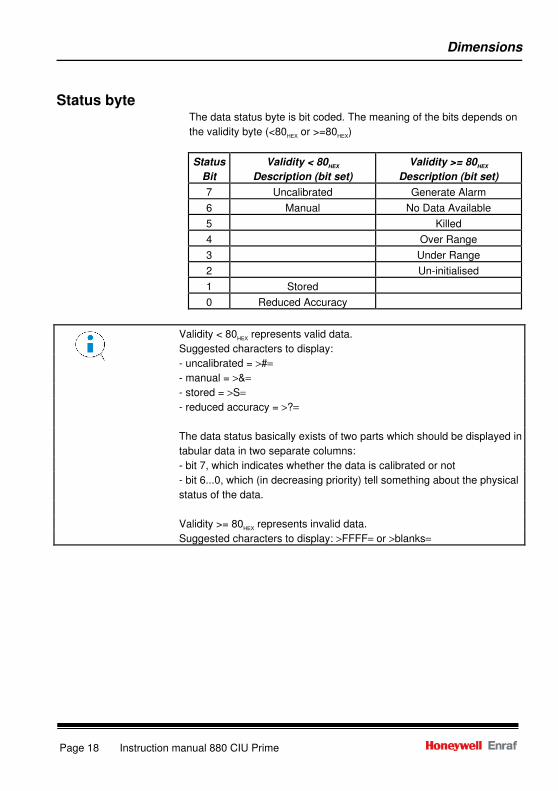
Status byte The data status byte is bit coded. The meaning of the bits depends on
the validity byte (<80HEX
or >=80HEX
)
Status
Bit
Validity < 80HEX
Description (bit set)
Validity >= 80HEX
Description (bit set)
7 Uncalibrated Generate Alarm
6 Manual No Data Available
5 Killed
4 Over Range
3 Under Range
2 Un-initialised
1 Stored
0 Reduced Accuracy
Validity < 80HEX
represents valid data.
Suggested characters to display:
- uncalibrated = >#=
- manual = >&=
- stored = >S=
- reduced accuracy = >?=
The data status basically exists of two parts which should be displayed in
tabular data in two separate columns:
- bit 7, which indicates whether the data is calibrated or not
- bit 6...0, which (in decreasing priority) tell something about the physical
status of the data.
Validity >= 80HEX
represents invalid data.
Suggested characters to display: >FFFF= or >blanks=
Modbus number representation
Instruction manual 880 CIU Prime Page 19
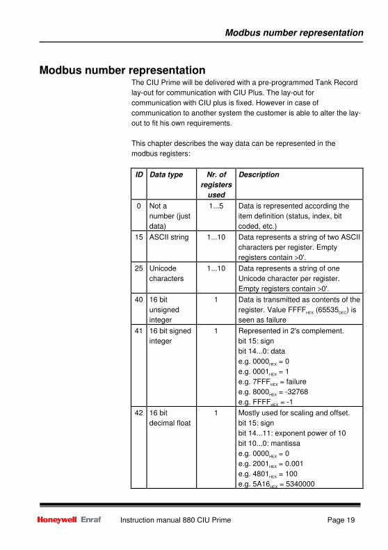
Modbus number representation The CIU Prime will be delivered with a pre-programmed Tank Record
lay-out for communication with CIU Plus. The lay-out for
communication with CIU plus is fixed. However in case of
communication to another system the customer is able to alter the lay-
out to fit his own requirements.
This chapter describes the way data can be represented in the
modbus registers:
ID Data type Nr. of
registers
used
Description
0 Not a
number (just
data)
1...5 Data is represented according the
item definition (status, index, bit
coded, etc.)
15 ASCII string 1...10 Data represents a string of two ASCII
characters per register. Empty
registers contain >0'.
25 Unicode
characters
1...10 Data represents a string of one
Unicode character per register.
Empty registers contain >0'.
40 16 bit
unsigned
integer
1 Data is transmitted as contents of the
register. Value FFFFHEX
(65535DEC
) is
seen as failure
41 16 bit signed
integer
1 Represented in 2's complement.
bit 15: sign
bit 14...0: data
e.g. 0000HEX
= 0
e.g. 0001HEX
= 1
e.g. 7FFFHEX
= failure
e.g. 8000HEX
= -32768
e.g. FFFFHEX
= -1
42 16 bit
decimal float
1 Mostly used for scaling and offset.
bit 15: sign
bit 14...11: exponent power of 10
bit 10...0: mantissa
e.g. 0000HEX
= 0
e.g. 2001HEX
= 0.001
e.g. 4801HEX
= 100
e.g. 5A16HEX
= 5340000
Modbus number representation
Page 20 Instruction manual 880 CIU Prime
ID Data type Nr. of
registers
used
Description
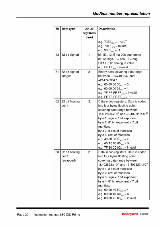
e.g. 73E8HEX
= 1Α1010
e.g. 7BFFHEX
= failure
e.g. 9001HEX
= -1
43 12 bit signed 1 bit 15...13: if not 000 see further:
bit 12: sign, 0 = pos., 1 = neg.
Bit 11...00: analogue value
e.g. EF FFHEX
= invalid
51 32 bit signed
integer
2 Binary data, covering data range
between -2147483647 and
+2147483647
e.g. 00 00 00 00HEX
= 0
e.g. 00 00 00 01HEX
= 1
e.g. 7F FF FF FFHEX
= invalid
e.g. FF FF FF FFHEX
= -1
52 32 bit floating
point
2 Data in two registers. Data is coded
into four bytes floating point,
covering data range between
-3.402823Α1038
and +3.402823Α1038
byte 1: sign + 7 bit exponent
byte 2: 8th bit exponent + 7 bit
mantissa
byte 3: 8 bits of mantissa
byte 4: rest of mantissa
e.g. 40 80 00 00HEX
= 4
e.g. 40 A0 00 00HEX
= 5
e.g. 7F 80 00 00HEX
= invalid
53 32 bit floating
point
(swapped)
2 Data in two registers. Data is coded
into four bytes floating point,
covering data range between
-3.402823Α1038
and +3.402823Α1038
byte 1: 8 bits of mantissa
byte 2: rest of mantissa
byte 3: sign + 7 bit exponent
byte 4: 8th bit exponent + 7 bit
mantissa
e.g. 00 00 40 80HEX
= 4
e.g. 00 00 40 A0HEX
= 5
e.g. 00 00 7F 80HEX
= invalid
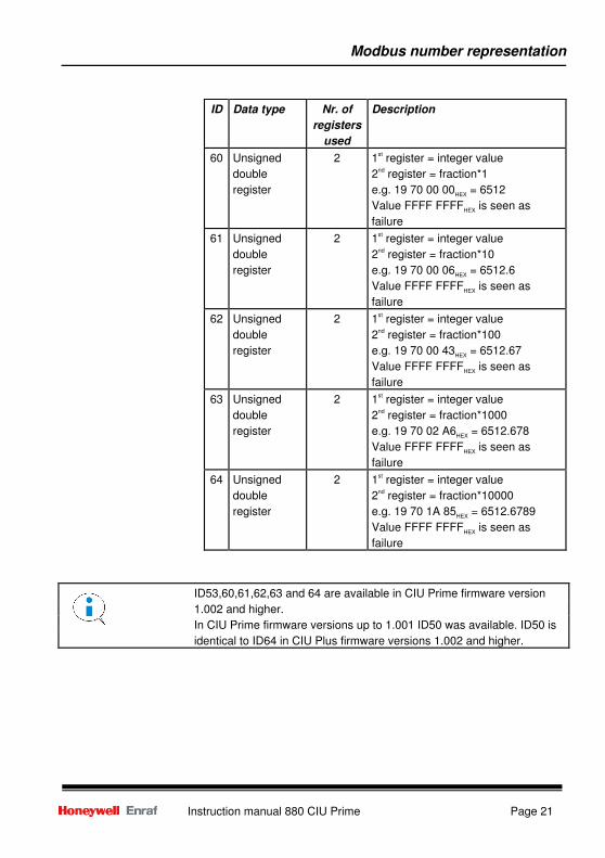
Modbus number representation
Instruction manual 880 CIU Prime Page 21
ID Data type Nr. of
registers
used
Description
60 Unsigned
double
register
2 1st register = integer value
2nd
register = fraction*1
e.g. 19 70 00 00HEX
= 6512
Value FFFF FFFFHEX
is seen as
failure
61 Unsigned
double
register
2 1st register = integer value
2nd
register = fraction*10
e.g. 19 70 00 06HEX
= 6512.6
Value FFFF FFFFHEX
is seen as
failure
62 Unsigned
double
register
2 1st register = integer value
2nd
register = fraction*100
e.g. 19 70 00 43HEX
= 6512.67
Value FFFF FFFFHEX
is seen as
failure
63 Unsigned
double
register
2 1st register = integer value
2nd
register = fraction*1000
e.g. 19 70 02 A6HEX
= 6512.678
Value FFFF FFFFHEX
is seen as
failure
64 Unsigned
double
register
2 1st register = integer value
2nd
register = fraction*10000
e.g. 19 70 1A 85HEX
= 6512.6789
Value FFFF FFFFHEX
is seen as
failure
ID53,60,61,62,63 and 64 are available in CIU Prime firmware version
1.002 and higher.
In CIU Prime firmware versions up to 1.001 ID50 was available. ID50 is
identical to ID64 in CIU Plus firmware versions 1.002 and higher.
Modbus number representation
Page 22 Instruction manual 880 CIU Prime
Scaling and offset Scaling and offset are defined as follows:
• The value of the data that will be available for the user is calculated as follows:
Register value = (data * scaling) + offset
• Per selected data entitya scaling and offset value can be entered. These entered values
are used for calculating the register value.
• The original data measured or calculated by the CIU Prime is available in the dimension
and resolution as defined by the dimension table.
• This data is represented in the requested representation in the output registers.
Modbus number representation
Instruction manual 880 CIU Prime Page 23
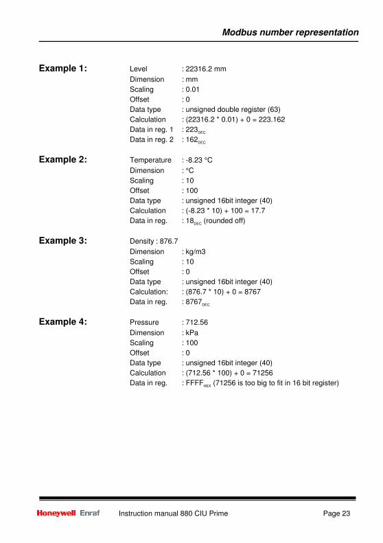
Example 1: Level : 22316.2 mm
Dimension : mm
Scaling : 0.01
Offset : 0
Data type : unsigned double register (63)
Calculation : (22316.2 * 0.01) + 0 = 223.162
Data in reg. 1 : 223DEC
Data in reg. 2 : 162DEC
Example 2: Temperature : -8.23 °C
Dimension : °C
Scaling : 10
Offset : 100
Data type : unsigned 16bit integer (40)
Calculation : (-8.23 * 10) + 100 = 17.7
Data in reg. : 18DEC
(rounded off)
Example 3: Density : 876.7
Dimension : kg/m3
Scaling : 10
Offset : 0
Data type : unsigned 16bit integer (40)
Calculation: : (876.7 * 10) + 0 = 8767
Data in reg. : 8767DEC
Example 4: Pressure : 712.56
Dimension : kPa
Scaling : 100
Offset : 0
Data type : unsigned 16bit integer (40)
Calculation : (712.56 * 100) + 0 = 71256
Data in reg. : FFFFHEX
(71256 is too big to fit in 16 bit register)
Maintenance / trouble shooting
Page 24 Instruction manual 880 CIU Prime
Maintenance / trouble shooting
Maintenance The CIU Prime requires neither preventive nor periodical maintenance.
Trouble shooting If something appears to be wrong, proceed as follows:
1. Check mains voltage: yes -> step 2
no -> check/replace
fuses
2. Check cabling: not connected -> connect
connected -> step 3
3. Check communication: yes -> finish
no -> step 4
4. Start >Ensite Pro=
5. Go to >Diagnostic data=
6. Press the >Update=-button to have the current values
7. Press the >Print=-button to store the data
8. Contact Honeywell Enraf with diagnostic data.
Cleaning of the housing of the CIU Prime should be done with a moist
cloth only.
After switching on of the CIU Prime it will take approximately 1 minute
before it will be able to communicate via the host ports.
The ´Alive´ LED (green LED under the red power LED) gives an
indication if the CIU Prime is in healthy condition.
In case healthy the LED will flash about every 0.75 second).
Note that the healthy flash rhythm is different from the flash rhythm of the
Alive LED on the CIU Plus.
Appendix
Instruction manual 880 CIU Prime Page 25
Appendix A Glossary
A
AmbientTemperature ID#103; Value of the tank=s ambient temperature.
AmbientTemperatureStat ID#104; Status of ID#103, AmbientTemperature.
AutomaticMeasurableValues
ID#80; Indicates (bit coded) which values can be automatically
measured (this doesn't necessarily mean that they are actually
measured). Bit n = 1: value can be measured automatically:
- Bit 0 = 1 Level [ID#38, ID#40]
- Bit 1 = 1 Temperature [ID#44]
- Bit 2 = 1 Water level [ID#42]
- Bit 3 = 1 Density [ID#50]
- Bit 4 = 1 Vapour temperature [ID#46]
- Bit 5 = 1 Vapour pressure [ID#48]
- Bit 6 = 1 Ambient Temperature [ID#103]
- Bit 7 = 1 Dummy scan (now used for FDI scan)
- Bit 14 ProductTC calc.mode: 0 = manual, 1 = calculated
- Bit 15 VCF calc. mode: 0 = manual, 1 = calculated
B
BackgroundTimeStamp ID#53; (Absolute) time when, in the background scan, the most recent
item was scanned.
C
CIUPrimeGeneralConfigurationCRC
ID#95; Checksum, calculated over general CIU Prime configuration
parameters (for W&M purposes).
CIUPrimeTankID ID#106; Holds (bit coded) the CIU Prime tank identifier:
- Bit 0..7 Tank number between 1 and 50
- Bit 8..15 RTU Address of the CIU Prime host port
CommStatus ID#10; Indicates (bit coded) the communication status:
- Bit 0 = 1 CIU Prime to Gauge comm. Ok. (Future) (Bit 0 does
not change when bit 1=0)
- Bit 1 = 1 CIU Plus to (active or passive) CIU Prime comm. Ok
Bits 14 and 15 are for internal use of the CIU Plus.
The length is fixed to 16 bits.
Value FFFF: tank/port not used.
Appendix
Page 26 Instruction manual 880 CIU Prime
- Bit 2 = 1 FieldPort on (active) CIU Prime Ok
ConfigurationStatus ID#78; Indicates (bit coded) the CIU and tank configuration status:
- Bit 0 = 1 Gauge configuration mismatch (Future)
- Bit 1 = 1 CIU Prime general configuration mismatch
- Bit 2 = 1 CIU Prime tank configuration mismatch
- Bit 3 = 1 CIU Plus general configuration mismatch
- Bit 4 = 1 CIU Plus tank configuration mismatch for this tank
- Bit 5 = 1 Ensite Pro general configuration mismatch
- Bit 6 = 1 Ensite Pro tank configuration mismatch
- Bit 7 = 1 CIU Prime record contains invalid verification
signature
D
DisplacerPosition ID#38; Value of the physical servo displacer position.
DisplacerPositionStatus ID#39; Status of ID#38, DisplacerPosition.
DObs ID#50; Value of the product density (copy of DObsHIMS [ID#116] or
DObsDipped [ID#112]).
DObsDipped ID#112; Value of the dipped density.
DObsDippedStatus ID#113; Status of ID#112, DObsDipped.
DObsHIMS ID#116; Value of the HIMS density.
DObsHIMSStatus ID#117; Status of ID#116, DObsHIMS.
DObsStatus ID#51; Status of ID#50, Dobs (copy of DObsHIMSStatus [ID#117] or
DObsDippedStatus [ID#113]).
E
ExternalContacts ID#37; Indicates (bit coded) the external contacts:
- Bit 0 = 1 External contact 1 active
- Bit 1 = 1 External contact 2 active
- Bit 2 = 1 External contact failure
- Bit 3 = 1 External contact not available in this instrument
Because of the representation as combined entity the useful length is
fixed to 3 bits.
Because of the representation as combined entity the length is fixed to 8
bits.
Because of the representation as combined entity the length is fixed to 8
bits.
Appendix
Instruction manual 880 CIU Prime Page 27
F
ForegroundTimeStamp ID#52; (Absolute) time when, in the foreground scan, the most recent
item was scanned.
G
GaugeCommands ID#7; Indicates (bit coded) the allowed gauge commands:
- Bit 0 = 1 Test not allowed
- Bit 1 = 1 Lock test not allowed
- Bit 2 = 1 Block not allowed
- Bit 3 = 1 Calibration not allowed
- Bit 4 = 1 Alarm test not allowed
- Bit 5 = 1 Tank profile not allowed
- Bit 6 = 1 Interface profile not allowed
- Bit 7 = 1 Water dip not allowed
- Bit 8 = 1 Reset Gauge not allowed
- Bit 9 = 1 Interface 2 command not allowed
GaugeLevelAlarms ID#36; Indicates (bit coded) gauge level alarms:
- Bit 0 = 1 Low Level alarm tripped
- Bit 1 = 1 High Level alarm tripped
- Bit 2 = 1 Alarm failure
- Bit 3 = 1 Gauge alarms not available in this instrument
GaugeStatus ID#6; Indicates (indexed) the (servo) gauge active status:
- 0 = Level gauge is measuring level
- 1 = Level gauge is in test
- 2 = Level gauge is in lock test
- 3 = Level gauge is blocked
- 4 = Level gauge is busy with a density profile measurement
- 5 = Level gauge is searching water level
- 6 = Level gauge end switch reached
- 10 = Level gauge has found waterlevel and is measuring it
- 255 = Level gauge is in failure
Because of the representation as combined entity the length is fixed to 8
bits.
Statuses 8 and 9 can only be detected when the ZLQ request is used for
the level measurement.
Because of the representation as combined entity the length is fixed to 8
bits.
Appendix
Page 28 Instruction manual 880 CIU Prime
GaugeType ID#5; Type of level measuring instrument. To get the instrument type
number, add 800 (decimal) to the GaugeType value. Example: Gauge
type value = 54 -> instrument 854. This entity is configured by Ensite
Pro.
H
HotStandbyStatus ID#9; Indicates (bit coded) the hot standby status:
- Bit 0 = 1 Primary CIU Prime is scanning this tank
- Bit 1 = 1 Primary CIU Prime is available for this tank
- Bit 2 = 1 Secondary CIU Prime is scanning this tank
- Bit 3 = 1 Secondary CIU Prime is available for this tank
- Bit 4 = 1 CIU Plus is passive member of a Hot-Standby pair
HydroMeterCorr ID#88; >0' is false, >1' means true.
HydroMeterCorrStatus ID#154; Status of ID#88, HydroMeterCorr.
M
MovingStatus ID#3; Indicates (indexed) the level moving status:
- 0 = Tank level is stable
- 1 = Tank level is moving up
- 2 = Tank level is moving down
- 3 = No valid movement status can be detected (e.g. manual level)
P
ProductLevel ID#40; Value of the product level.
ProductLevelStatus ID#41; Status of ID#40, ProductLevel.
ProductTemp ID#44; Value of the product temperature.
ProductTempStatus ID#45; Status of ID#44, ProductTemp.
Because of the representation as combined entity the length is fixed to 8
bits.
Because of the representation as combined entity the useful length is
fixed to 5 bits.
Because of the representation as combined entity the length is fixed to 4
bits.
Appendix
Instruction manual 880 CIU Prime Page 29
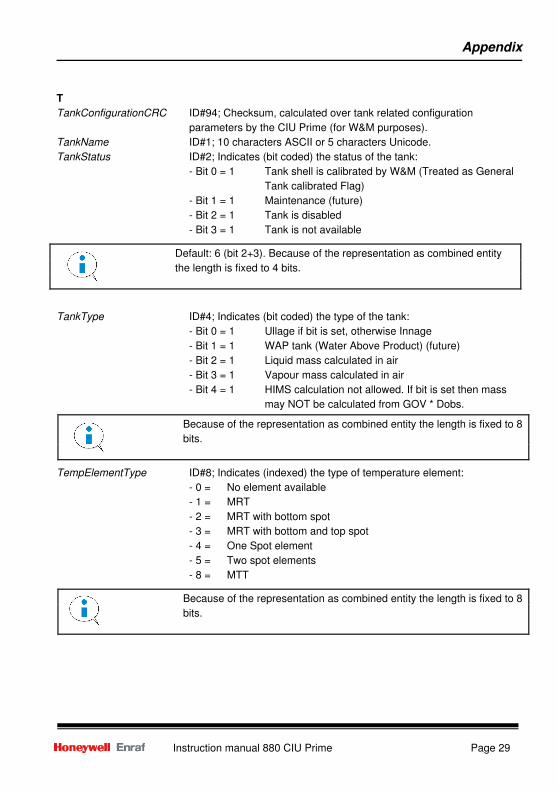
T
TankConfigurationCRC ID#94; Checksum, calculated over tank related configuration
parameters by the CIU Prime (for W&M purposes).
TankName ID#1; 10 characters ASCII or 5 characters Unicode.
TankStatus ID#2; Indicates (bit coded) the status of the tank:
- Bit 0 = 1 Tank shell is calibrated by W&M (Treated as General
Tank calibrated Flag)
- Bit 1 = 1 Maintenance (future)
- Bit 2 = 1 Tank is disabled
- Bit 3 = 1 Tank is not available
TankType ID#4; Indicates (bit coded) the type of the tank:
- Bit 0 = 1 Ullage if bit is set, otherwise Innage
- Bit 1 = 1 WAP tank (Water Above Product) (future)
- Bit 2 = 1 Liquid mass calculated in air
- Bit 3 = 1 Vapour mass calculated in air
- Bit 4 = 1 HIMS calculation not allowed. If bit is set then mass
may NOT be calculated from GOV * Dobs.
TempElementType ID#8; Indicates (indexed) the type of temperature element:
- 0 = No element available
- 1 = MRT
- 2 = MRT with bottom spot
- 3 = MRT with bottom and top spot
- 4 = One Spot element
- 5 = Two spot elements
- 8 = MTT
Default: 6 (bit 2+3). Because of the representation as combined entity
the length is fixed to 4 bits.
Because of the representation as combined entity the length is fixed to 8
bits.
Because of the representation as combined entity the length is fixed to 8
bits.
Appendix
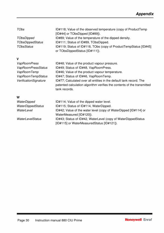
Page 30 Instruction manual 880 CIU Prime
TObs ID#118; Value of the observed temperature (copy of ProductTemp
[ID#44] or TObsDipped [ID#89]).
TObsDipped ID#89; Value of the temperature of the dipped density.
TObsDippedStatus ID#111; Status of ID#89, TObsDipped.
TObsStatus ID#119; Status of ID#118, TObs (copy of ProductTempStatus [ID#45]
or TObsDippedStatus [ID#111]).
V
VapRoomPress ID#48; Value of the product vapour pressure.
VapRoomPressStatus ID#49; Status of ID#48, VapRoomPress.
VapRoomTemp ID#46; Value of the product vapour temperature.
VapRoomTempStatus ID#47; Status of ID#46, VapRoomTemp.
VerificationSignature ID#77; Calculated over all entities in the default tank record. The
patented calculation algorithm verifies the contents of the transmitted
tank records.
W
WaterDipped ID#114; Value of the dipped water level.
WaterDippedStatus ID#115; Status of ID#114, WaterDipped.
WaterLevel ID#42; Value of the water level (copy of WaterDipped [ID#114] or
WaterMeasured [ID#120]).
WaterLevelStatus ID#43; Status of ID#42, WaterLevel (copy of WaterDippedStatus
[ID#115] or WaterMeasuredStatus [ID#121]).
Appendix
Instruction manual 880 CIU Prime Page 31
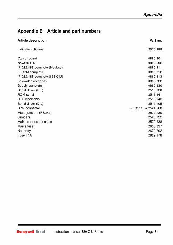
Appendix B Article and part numbers
Article description Part no.
Indication stickers 2075.998
Carrier board 0880.601
Newt 80165 0880.602
IP-232/485 complete (Modbus) 0880.811
IP-BPM complete 0880.812
IP-232/485 complete (858 CIU) 0880.813
Keyswitch complete 0880.822
Supply complete 0880.830
Serial driver (DIL) 2518.120
ROM serial 2518.941
RTC clock chip 2518.942
Serial driver (DIL) 2519.105
BPM connector 2522.110 + 2524.968
Micro jumpers (RS232) 2522.130
Jumpers 2523.922
Mains connection cable 2570.238
Mains fuse 2655.337
Net entry 2670.202
Fuse T1A 2829.978
Appendix
Page 32 Instruction manual 880 CIU Prime
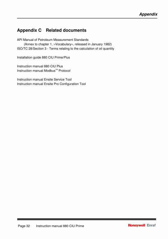
Appendix C Related documents
API Manual of Petroleum Measurement Standards
(Annex to chapter 1, >Vocabulary=, released in January 1982)
ISO/TC 28/Section 3 - Terms relating to the calculation of oil quantity
Installation guide 880 CIU Prime/Plus
Instruction manual 880 CIU Plus
Instruction manual ModbusTM
Protocol
Instruction manual Ensite Service Tool
Instruction manual Ensite Pro Configuration Tool

Notes
Instruction manual 880 CIU Prime Page 33

Notes
Page 34 Instruction manual 880 CIU Prime

Notes
Instruction manual 880 CIU Prime Page 35
Page 36 Instruction manual 880 CIU Prime
Delftechpark 39 2628 XJ Delft Tel. :+31 15 2701 100 E-mail : [email protected] Website: www.honeywell.com/ps PO Box 812 2600 AV Delft The Netherlands We at Honeywell Enraf are committed to excellence. Information in this publication is subject to change without notice Enraf is a registered trade mark. Enraf B.V. Netherlands