
Instruction Manual - Carlin Combustion Technology, Inc.
26
Contents PLEASE read this first ...........................................................2 Codes and Standards ............................................................2 301GAS Burner at-a-glance ..................................................3 Prepare Site • Prepare Burner • Mount Bburner ..................4 Install Gas Piping.................................................................10 Wire Burner ......................................................................... 11 Check System • Start-up Burner/Appliance .......................13 Perform Checkout Procedures • Fill Out Certificate ..........18 Maintenance and Service Procedures.................................20 Troubleshooting .................................................................. 21 Dimensions and Mounting Information ............................... 23 Replacement Parts ............................................................. 24 Installation/Service Certificate ............................................ 26 Ratings Input: .............................................401,000 to 1,100,000 Btuh Fuels: ........................................... Natural gas or propane gas Max. supply pressure .............................. 14 inches w.c. Min. supply pressure ................................. 5 inches w.c. Manifold pressure................................... 3.5 inches w.c. Electrical: Power ............................................ 120V/60 Hz/1-Phase Motor ................................ 1/6 HP, 3450 RPM, 1.8 amps Total Current ....................................... Approx. 2.5 amps Ignition: ............................ Carlin Model 41800 solid state ignitor Control: ..............Carlin Model 60200FR microprocessor control Agencies: ........................................................................ UL Listed Installer/servicer — Except where specifically stated other- wise, this manual must be used only by a qualified service technician. (In the state of Massachusetts, this product must be installed by a licensed Plumber or Gas Fitter.) Failure to comply with this or other requirements in this manual could result in severe personal injury, death or substantial property damage. User — Refer only to User’s Information booklet for information regarding operation of this burner. The burner Instruction Manual is intended only for your service techni- cian. The burner and heat exchanger must be inspected and started at least annually by your service technician. ™ 126 Bailey Road North Haven, CT 06473 Ph 203-680-9401 Fx 203-680-9403 Carlin Combustion Technology, Inc. T ECH SUPPORT 800-989-2275 carlincombustion.com © Copyright 2014 — Carlin Combustion Technology, Inc. Instruction Manual
Transcript of Instruction Manual - Carlin Combustion Technology, Inc.

ContentsPLEASE read this first ...........................................................2Codes and Standards ............................................................2301GAS Burner at-a-glance ..................................................3Prepare Site • Prepare Burner • Mount Bburner ..................4Install Gas Piping .................................................................10Wire Burner .........................................................................11Check System • Start-up Burner/Appliance .......................13Perform Checkout Procedures • Fill Out Certificate ..........18Maintenance and Service Procedures .................................20Troubleshooting .................................................................. 21Dimensions and Mounting Information ............................... 23Replacement Parts ............................................................. 24Installation/Service Certificate ............................................ 26
RatingsInput: .............................................401,000 to 1,100,000 Btuh
Fuels: ........................................... Natural gas or propane gas
Max. supply pressure .............................. 14 inches w.c.
Min. supply pressure ................................. 5 inches w.c.
Manifold pressure ................................... 3.5 inches w.c.
Electrical: Power ............................................120V/60 Hz/1-Phase
Motor ................................1/6 HP, 3450 RPM, 1.8 amps
Total Current .......................................Approx. 2.5 amps
Ignition: ............................Carlin Model 41800 solid state ignitor
Control: ..............Carlin Model 60200FR microprocessor control
Agencies: ........................................................................UL Listed
Installer/servicer — Except where specifically stated other-wise, this manual must be used only by a qualified service technician. (In the state of Massachusetts, this product must be installed by a licensed Plumber or Gas Fitter.) Failure to comply with this or other requirements in this manual could result in severe personal injury, death or substantial property damage.
User — Refer only to User’s Information booklet for information regarding operation of this burner. The burner Instruction Manual is intended only for your service techni-cian. The burner and heat exchanger must be inspected and started at least annually by your service technician.
™
126 Bailey Road North Haven, CT 06473Ph 203-680-9401 Fx 203-680-9403
Carlin Combustion Technology, Inc.
Tech support 800-989-2275 carlincombustion.com
© Copyright 2014 — Carlin Combustion Technology, Inc.
Instruction Manual

Model 301GAS burner — Instruction manual
MN301GAS 012516– 2 –
Where appliance instructions differ from this manual, follow the appliance instructions.
PLEASE read this first . . .
Special attention flagsPlease pay particular attention to the following when you see them throughout this manual.
Notifies you of hazards that WILL cause severe personal injury, death or substantial property damage.
Notifies you of hazards that CAN cause severe personal injury, death or substantial property damage.
Notifies you of hazards that WILL or CAN cause minor personal injury or property damage.
Notifies you of special instructions on installation, operation or maintenance that are important, but are not normally related to injury or property damage hazards.
Follow the guidelines below to avoid potential severe personal injury, death or substantial property damage.
Installer/service technician . . .• Read all instructions before proceeding. Perform all procedures,
and in the order given to avoid potential of severe personal injury, death or substantial property damage.
• Before leaving the site after start-up or service, review the User’s information manual with the user. Make the user aware of all potential hazards and perform the training outlined below.
Train the user . . .• To properly operate the burner/appliance per this manual and the
appliance instructions and the User’s information manual.• To keep this manual at or near the burner/appliance for ready
access by the user and service technician.• To contact the service technician, gas supplier or fire department
should the user smell gas.• To keep the appliance space free of flammable liquids or vapors
and other combustible materials.• Do not use laundry products, paints, varnishes or other chemicals
in the room occupied by the burner/appliance.• To contact the service technician at least annually for start-up and
burner/appliance service.
When servicing the burner . . .• Disconnect electrical supply to burner before attempting to
service to avoid electrical shock or possible injury from moving parts.
• Burner and appliance components can be extremely hot. Allow all parts to cool before attempting to handle or service to avoid potential of severe burns.
General informationBurner applicationsFollow all instructions in this manual and the appliance manual. Where appliance instructions differ from this manual, follow the appliance instruc-tions. Read the label attached to the burner air tube to verify the burner is correct for the appliance being used. See page 8 for procedures.
Damage or shortage claimsThe consignee of the shipment must file damage or shortage claims immediately against the transportation company.
When calling or writing about the burner . . .Please provide us with the UL serial number and burner model number to assist us in locating information. Enter this information on the Installation Certificate in this manual. The certificate information can be helpful when troubleshooting or obtaining replacement parts.
Fill out burner adjustment labelFill out the burner adjustment label, located on the housing above the rating label after completing installation and burner setup.
Should overheating occur: (1) shut off the manual gas control to the appliance, (2) do not shut off the control switch to the pump or blower.
Codes and Standards The installer/servicer is solely responsible for compliance
with all applicable codes and standards.
Burner listingsCarlin 301GAS burners are tested and approved under standards UL795 and CGA 3.4-latest edition.
CodesBurner/appliance installations must comply with all applicable lo-cal codes and, where applicable, with the National Fuel Gas Code, ANSI Z223.1/NFPA 54-latest edition, and the National Electrical code, ANSI/NFPA 70-latest edition for U. S. installations or B149.1/B149.2 Installation Code, and CSA C22.1 Canadian Electrical Code Part 1 for Canadian installations.
For Massachusetts Applications1. For 301GAS burner applications in the Commonwealth of Massachusetts, the burner input may not exceed 999,999 Btuh. 2. Model 301GAS burners for use in the Commonwealth of Massachusetts must be equipped with Carlin 60200FRN non-recycling primary controls.
these controls will lockout on flame failure.

Model 301GAS burner — Instruction manual
MN301GAS 012516 – 3 –
Where appliance instructions differ from this manual, follow the appliance instructions.
301GAS Burner at-a-glance
1 Burner gas connection, 1” NPT2 Air tube (flange omitted for clarity), with powder coat paint finish3 Flame rod/insulator assembly4 Combustion head5 Gas saddle connection gasket6 Gas manifold7 Ignition electrode/insulator assembly8 Static disk assembly (low input range shown)9 Hinged burner flange door – for access and removal of combustion head/gas
manifold assembly10 Ignitor (Carlin Model 41800 solid state electronic ignitor — 9,000 volts,
continuous duty rated)
11 Hinged cover plate (for access to blower wheel & electrodes)12 Airflow proving switch — Prevents burner from firing if air is not moving13 Air band — Only a single adjustment required for setting combustion air; see
page 7 for starting setting based on input14 Door interlock switch — prevents burner operation if flanged door is open15 Primary control — Carlin Model 60200FR microprocessor-based interrupted
ignition flame supervisory control (flame rectification)16 Burner junction box (installer electrical entrance)17 Motor (with permanently-lubricated bearings and thermal overload protection)

Model 301GAS burner — Instruction manual
MN301GAS 012516– 4 –
Where appliance instructions differ from this manual, follow the appliance instructions.
1. Prepare Site • Prepare Burner • Mount Burner
Vent system
Inspect, repair and/or replace vent system Do not install this burner unless you have verified the entire
vent system and the appliance are in good condition and comply with all applicable codes. And . . .
The vent and chimney must be sized and constructed in accordance with all applicable codes. If intended for use with an oil burner as well, the vent system must comply with relevant codes for both gas and oil firing.
The vent system must not be pressurized unless the vent piping and vent system are designed accordingly. The vent must provide draft at all times (negative pressure in vent).
Do not install or use an existing manual damper in the vent connector or vent.
Do not connect the appliance vent connector to a chimney or vent serving a fireplace, incinerator or solid-fuel-burning apparatus.
In a cold climate, do not vent into a masonry chimney that has one or more sides exposed to the outside. Install a listed stainless steel liner to vent the flue products.
A defective vent system could result in severe personal injury, death or substantial property damage.
Vent/chimney sizing• Follow all local codes when sizing the vent and chimney.• Refer to the appliance manufacturer’s manual, when available, for venting
recommendations.
Prepare vent/chimney• Secure all metal vent joints with screws, following the vent manufacturer’s
instructions. Seal all joints in the vent system and chimney. Repair ma-sonry chimney lining and repair all mortar joints as needed.
• Per ANSI Z21-8, install a double-acting barometric draft regulator in the vent piping. (The damper must be located in the same space as the ap-pliance.) Install a manual reset spill switch on the draft regulator outlet per instructions. Wire the switch into the appliance limit circuit to shut off the appliance/burner if sustained downdraft should occur. Refer to the appliance manufacturer’s instruction manual for recommendations regarding the need for a barometric draft regulator.
• Provide support for the vent piping. Do not rest the weight of any of the vent piping on the appliance flue outlet.
Figure 1 Vent and vent connector installations, typical

Model 301GAS burner — Instruction manual
MN301GAS 012516 – 5 –
Where appliance instructions differ from this manual, follow the appliance instructions.
Figure 2 Locating combustion air/ventilation openings
1. Prepare Site • Prepare Burner • Mount Burner (continued)
Combustion air/ventilation openings
General Installing the burner/appliance in a space that does not
provide enough air for combustion and ventilation can re-sult in severe personal injury, death or substantial property damage. Follow all applicable codes and guidelines below to ensure space has sufficient air openings.
Exhaust fans and negative pressure conditions — Isolate the boiler room from areas subject to negative pressure. Size combustion air openings to ensure neutral air pressure in the boiler room whenever the burner operates.
Make sure the space provides enough ventilation to prevent overheating of the appliance, burner and controls. If there is risk of overheating, you must install ventilation air openings sized large enough to provide air for cooling the equipment. Failure to provide ventilation can result in severe personal injury, death or substantial property damage.
The space and combustion air supply must not contain corrosive contaminants, such as laundry products, paints, varnishes or other chemicals.
Sizing air openingsFollow all applicable codes and the appliance instruction manual (when available) to size combustion air openings. Use the following guidelines when appliance instructions are not available.• All air from inside building (building must be well-ventilated): Size air openings for a free area (after louver deduction) of at least 1
square inch per 1,000 Btuh input of all appliances in the space.• All air through openings to outside:
Locating air openingsFollow all applicable codes and the appliance instruction manual (when available) to size combustion air openings. Refer to Figure 2 when ap-pliance instructions are not available.
Free area estimatingWhen specific information on the free area of louvers is not available, estimate free area as:• wood louvers — free area = area times 0.25.• metal louvers or grilles — free area = area times 0.60.• screens, when used must be no smaller than ¼ inch mesh.
Motorized vent dampersWire the vent damper end switch to prevent operation of the burner until the air opening louvers are fully open.
Combustion air/ventilation opening checklist• Verify that openings are unobstructed.• Verify that appliance space and air source spaces are free of:
– Gasoline or other flammable liquids or vapors.– Combustible materials.– Air contaminants, such as laundry products, paint, thinner, varnish,
etc.• Confirm with user that the area will be kept free of these materials at all
times.
Verify clearances• Verify that the burner/appliance will maintain all clearances to combustible
walls or floor and all clearances required for service/maintenance as required in the appliance manual and applicable codes.

Model 301GAS burner — Instruction manual
MN301GAS 012516– 6 –
Where appliance instructions differ from this manual, follow the appliance instructions.
1. Prepare Site • Prepare Burner • Mount Burner (continued)
Prepare the appliance Clean the appliance: Clean the appliance thoroughly and
seal all joints. Test all electrical components and verify the relief valve works (boilers only).
Burner input: Install a gas burner sized for the normal input rating of the appliance. Do not install a burner with a higher firing rate than the appliance rating. Do not install a burner with a firing rate more than 10% lower than the appliance rating. The appliance and vent system could be damaged due to condensation.
Seal the appliance: Seal all flue-gas containing joints. Seal all connections to the vent piping or breeeching.
Verify combustion chamber dimensions comply with the minimum dimensions shown in Figure 3, page 7. Install or replace chamber liner if required by the appliance manu-facturer. The burner must not extend into the combustion chamber. The end of the burner air tube must be within ¼" of the inside face of the chamber. If the space around the burner air tube is more than ¼", wrap the burner air tube with minimum 2300-°F-rated ceramic fiber blanket to seal off the gap.
Repair or replace damaged appliance components. Inspect the appliance thoroughly. Follow appliance manufacturer’s guidelines for repair or replacement of any component found defective.
When cleaning the appliance or working with ceramic fiber refractories or fiberglass insulation, see WARNING on this page.
Failure to comply with the above could result in severe personal injury, death or substantial property damage.
Ceramic fiber or Fiberglass insulation
Ceramic fiber materials, such as chamber liners, may contain carcinogenic particles (chrystobalites) after exposure to heat. Airborne particles from fiberglass or ceramic fiber components have been listed as potentially carcinogenic by the State of California. Take the following precautions when removing, replacing and handling these items.
Avoid breathing dust and avoid contact with skin or eyes. Wear long-sleeved, loose-fitting clothing, gloves and eye protection. Use a NIOSH N95 certified respirator. This respirator meets requirements for protection from chrystobalites. Actual job requirements or NIOSH regulations may require other or additional protection. For information, refer to the NIOSH website, http://www.cdc.gov/niosh/homepage.html.
Ceramic fiber removal: To prevent airborne dust, thoroughly wet ceramic fiber with water before handling. Place ceramic fiber materials in a plastic bag and seal to dispose.
Avoid blowing, tearing, sawing or spraying fiberglass or ceramic fiber materials. If such op-erations are necessary, wear extra protection to prevent breathing dust.
Wash work clothes separately from other laun-dry. Rinse clothes washer thoroughly afterwards to prevent contamination of other clothing.
NIOSH First aid procedures: Eye exposure — irrigate immediately Breathing — fresh air.
Prepare appliance for burner mounting Positive overfire pressure applications: When firing with
positive overfire pressure, do not exceed the pressure specified in the appliance manual.
Positive overfire pressure reduces maximum burner ca-pacity. See Table 1 notes for estimated reduction in burner capacity with pressurized firing.
Failure to comply could result in severe personal injury, death or substantial property damage.
Check bolt locationsVerify that the burner flange bolt layout matches that of the appliance. See page 19 for required dimensions and bolt locations.

Model 301GAS burner — Instruction manual
MN301GAS 012516 – 7 –
Where appliance instructions differ from this manual, follow the appliance instructions.
1. Prepare Site • Prepare Burner • Mount Burner (continued)
Table 1 Burner orifice sizing, air settings and minimum combustion chamber dimenions (see Figure 3)
Figure 3 Chamber dimensions & tube configurationsPrepare burner and components Do not install or operate the burner if any component is dam-
aged or if burner does not comply with the specifications of Table 1 and other guidelines in this manual.
Combustion head/air tube configurations• 301GAS burners are supplied with either an “B” or “C” head and air tube
combination. The “B” head/tube is designed for the low range from 401 to 700 MBH. The “C” head/tube is for the high range from 550 MBH to 1,100 MBH.
Air tube insertion length (UTL)• Usable air tube length (UTL) is the distance from mounting flange to end
of air tube. Verify that the end of the air tube will be flush with, or no more than ¼ inch short of, the inside of the appliance combustion chamber front wall when the burner is mounted. See Figure 3 and Table 1 for further information.

Model 301GAS burner — Instruction manual
MN301GAS 012516– 8 –
Where appliance instructions differ from this manual, follow the appliance instructions.
1. Prepare Site • Prepare Burner • Mount Burner (continued)
Figure 5 Combustion head
Figure 4 Removing combustion head/gas manifold
Inspect/correct flame rod/electrode• Before installing the burner in the appliance, inspect the flame rod
and electrode.• Verify the dimensions shown in this page.• If the flame rod or electrode is damaged or not in the correct position,
follow the procedure below to access and adjust.
To access the flame rod or electrode1. If the burner is not installed in an appliance, you can inspect the flame
rod and electrode from the front of the burner. To change the position of the flame rod or electrode, you must remove the combustion head/gas manifold assembly from the burner. See “D” thru “H” below.
2. To remove the combustion head/gas manifold assembly, you must disconnect the gas piping and swing the burner flange door open. See Figure 4, and proceed to:a. Turn off all power to the burner and appliance before proceeding.b. Close the manual gas valve on the gas supply line.c. Disconnect the burner gas train union.d. Remove the gas pipe at the burner air tube.e. Remove the four nuts securing the burner hinged door flange.f. Swing the burner open at the door flange.g. Remove the two screws holding the gas manifold saddle to the air tube.
(Save the gasket.)h. Disconnect electrode and flame rod wires then slide the burner combus-
tion head/gas manifold assembly out the end of the open air tube.3. Position Electrode first — Make sure the electrode is placed according
to the dimensions shown in Figure 6. To adjust the electrode, loosen the electrode clamp screw and slide/rotate into position.
Tighten the electrode clamp screw after positioning. The shim rod welded in the clamp’s v-groove aligns the bracket when tightening.
4. Position Flame rod after setting electrode — Make sure the flame rod is located as shown in Figure 7. To adjust, loosen the flame rod clamp screw. Tighten the screw to secure the flame rod in place.
5. Replace the combustion head/manifold in the air tube.
Figure 6 Electrode location
Figure 7 Flame rod location
After electrode is adjusted, use a 1/8” drill bit to check electrode spacing to surface per Figure 6. Also use the drill bit to make sure the electrode is no closer than 1/8” to any other metal surface.

Model 301GAS burner — Instruction manual
MN301GAS 012516 – 9 –
Where appliance instructions differ from this manual, follow the appliance instructions.
Mount burner in appliance• Verify appliance burner front plate dimensions and bolt locations.• Slide gasket supplied with burner over end of air tube.• Insert burner into appliance opening and bolt in place.• Level the housing if necessary by loosening the set screws securing the
housing to the air tube. Retighten the set screws.
Inspect components and wiring• Visually inspect all burner components and wiring.• Verify that wiring is intact and leads are securely connected.• Verify that all burner components are in good condition.• Check gas pressure switch settings. Set the low gas pressure switch at
manifold setting minus 50%. Set the high gas pressure switch at manifold setting plus 50%.
Figure 8 Gas orifice location
Install gas train on burner1. The standard burner gas train is shipped fully assembled, with the piping
disconnected at the gas train union. See separate instructions if installing an optional knocked down gas train.
2. Connect the gas train at the union (Figure 9).
To avoid damage to gas train components, do not hold compo-nents with a pipe wrench or overtighten. Use only a crescent wrench or other means. Failure to comply could result in severe personal injury, death or substantial property damage.
3. Connect the flexible conduit, pre-attached to the primary control J-box, to the gas train J-box, and attach the wires to the terminal strip inside the gas train J-box.a. Match wire colors of the incoming wires to those pre-wired to the terminal
strip inside the gas train J-box.b. See the label in the burner junction box or the wiring diagram on page 11.
Gas valve vent opening — If local codes require, install pip-ing from vent connection to outside, sized and installed as required by codes. A vent limiting orifice is provided. Install in vent opening, if starts are hard, before piping to outside.
Figure 9 Gas train installation
Inspect/redrill gas orifice If the burner is installed, you must disconnect power to burner
and close main manual gas valve before proceeding. Failure to do so could result in severe personal injury, death or substantial property damage.
In the state of Massachusetts, when lever-type gas shutoffs are used, they must be T-handle type only.
1. Turn off power to the burner/appliance before proceeding.2. Close main manual gas valve in gas supply line to burner.3. Disconnect the burner gas train union if the burner/gas train is installed.
See Figures 8 and 9.4. Locate the correct orifice drill size in Table 1, page 7 (or appliance
manual). Then check actual orifice size using that size drill bit.5. If the gas orifice is smaller than required, unscrew the orifice nipple
from the elbow. Then redrill the orifice to the correct size. Replace the gas train, using only pipe dope listed for use with liquefied petroleum gases.
6. If the gas orifice is larger than required, remove the orifice nipple from the elbow. Obtain a replacement orifice nipple. If necessary, drill the correct orifice hole in the new orifice to the correct size.
7. Replace gas train. Seal pipe joints with a small amount of pipe dope. Use only pipe dope approved for use with propane gas.
1. Prepare Site • Prepare Burner • Mount Burner (continued)

Model 301GAS burner — Instruction manual
MN301GAS 012516– 10 –
Where appliance instructions differ from this manual, follow the appliance instructions.
2. Install Gas Piping from Meter to Combination Gas Train
Code complianceThe burner/appliance installation must comply with codes listed on page 2 and any other locally applicable codes.
Piping from gas meter to burner Connect from the gas supply to the burner gas train inlet using
new, clean black iron pipe and malleable iron fittings only. Do not use copper, brass, cast iron or galvanized pipe or fittings.
Provide support for gas piping. Do not rest the weight of the gas piping on burner gas train.
Provide a support for the burner gas train. Apply pipe dope sparingly at all joints. Use only pipe dope listed
for use with propane gas. Do not use pipe sealing tape. Do not hold the gas valve with pipe wrench. Use crescent
wrench or other smooth-jawed device. Do not overtighten. Failure to comply with above could result in severe personal
injury, death or substantial property damage.
1. If possible, install a new gas line directly from the gas meter. If you are using an existing gas line, verify it is clean and in good condition, and verify it is large enough to handle the load of all connected appliances.
2. When branching from a common gas line, do not tap off from the bottom of horizontal sections — only from the side or top.
3. Install a main manual shutoff valve, sediment trap and ground joint union near the burner combination gas valve connection as shown in Figure 10.
4. If the burner is installed inside an appliance jacket, install the main manual gas valve and sediment trap external to the jacket.
5. Size piping (or verify size) using Table 2. You will find additional information on gas line sizing in the National Fuel Gas Code, NFPA 54/ANSI Z223.1, or B149.1/B149.2 Installation Code for Canadian Installations.
Gas supply pressure — natural or propane• Maximum supply pressure: 14 inches w.c.• Minimum supply pressure: 5 inches w.c.
Do not expose the gas train to gas pressure in excess of 14 inches water column. Higher pressure could damage the valve seat, resulting in potentially hazardous condition. When pres-sure testing piping at higher pressures, disconnect burner from gas line before testing.
If the gas supply pressure can exceed 14 inches water col-umn at any time, you must install a lockup type gas pressure regulator in the gas supply piping, ahead of the main manual gas valve installed at the burner.
Test and purge gas lineRead WARNING above.Pressure test and purge the line. Pressure testing should be done by the gas supplier or utility, following all applicable codes.
1 Pipe to meter or branch
2 T-handle main manual gas valve
3 Use clean, burr-free black iron pipe and malleable iron fittings
4 Ground joint union
Figure 10 Connecting gas supply piping to burner
Table 2 Capacities of black iron pipe, cubic feet gas/hour
5 Sediment leg
6 Upstream pressure tap, 1/4”
7 Outlet pressure tap, 1/4”
8 Gas regulator access screw
9 Gas valve wire junction box
NATURAL GASCapacities in Cubic feet per hour
for Schedule 40 metal pipe
Pipe size (inches)
Total length of gas piping, from meter to burner connection (feet)
20 40 60 80 100
Natural gas @ .60 specific gravity, pressure drop 0.3 in. w.c. (note 1)
1¼ 730 500 400 350 3051½ 1,100 760 610 530 4602 2,100 1,450 1,150 990 870
2½ 3,300 2,300 1,850 1,600 1,400
Natural gas @ .60 specific gravity, pressure drop 0.5 in. w.c. (note 1)
1 465 320 260 220 1951¼ 950 660 530 460 4001½ 1,460 990 810 690 6202 2,750 1,900 1,520 1,300 1,150
2½ 4,350 3,000 2,400 2,050 1,850
Note 1 For natural gas with specific gravity other than 0.60, consult National Fuel Gas Code, NFPA 54/ANSI Z223.1, or Canadian B149.1/B149.2 for correction factor.
PROPANE GASCapacities in Btuh for
Schedule 40 metal pipe
Propane gas @ 1.5 specific gravity, pressure drop 1 psi½ 1,684 1,157 929 795 705¾ 3,521 2,420 1,943 1,663 1,4741 6,632 4.558 3,660 3,133 2,776
Propane gas @ 1.5 specific gravity, pressure drop 0.5 in. w.c.1 735 506 411 348 308
1¼ 1502 1043 838 727 6321½ 2308 1565 1281 1091 980

Model 301GAS burner — Instruction manual
MN301GAS 012516 – 11 –
Where appliance instructions differ from this manual, follow the appliance instructions.
3. Wire Burner
General wiring requirements Read and follow the guidelines below. Failure
to comply could result in severe personal injury, death or substantial property damage.
Electrical shock hazard — Disconnect electrical supply to the burner before attempting to service.
Electrically ground burner — The burner must be grounded in accordance with local codes or, in the absence of local codes, with the National Electrical Code, ANSI/NFPA 70, or CSA C22.1/CSA C22.2 Canadian Electrical Code for Ca-nadian installs.
Label all wires before removing for servicing. Wiring errors could result in unsafe appliance/burner opera-tion.
Read appliance manufacturer’s instructions completely before wiring burner.
The 60200FR control requires a constant 120 vac power source from the appliance as well as power from the appliance limit circuit. See Figure 11. Check polarity carefully. If hot and neutral wires are reversed at appliance power source, the control will lockout on flame failure.
If replacing any of the wire supplied with the burner, use minimum #18 AWG 125°C or better.
Verify power supply1. The burner requires a 120 vac/60 hz/single-phase power supply, with at least a 10-
amp fuse. The current draw will be (when equipped with typical motor and Carlin 41800 electronic ignitor) approximately:
2. The 120 vac power connections to the black and red/white wires of the 60200FR
must be the same polarity from the same power source. DO NOT attempt to supply separate power sources. Check the power from the appliance with a voltmeter. Verify that the supply to the black and red/white wires are from the 120 vac HOT side and that the power is no less than 102 vac nor more than 132 vac.
Checking burner flame signalThe 60200FR uses flame rectification to detect the flame. Because the grounded metal surface area near the flame rod is much larger than the surface of the flame rod, current flows through the flame more easily in one direction than the other. This causes an AC voltage applied to the flame rod to result in a DC current. (Note that, if the flame rod should touch a grounded metal part, the current would be AC, not DC, and the control would not sense flame causing a flame failure.)The minimum flame signal needed to satisfy the 60200FR sensing circuit is 0.8 microamps. The control will register flame failure at any lower signal.
Code complianceThe burner/appliance installation must comply with codes listed on page 2 and any other locally applicable codes.

Model 301GAS burner — Instruction manual
MN301GAS 012516– 12 –
Where appliance instructions differ from this manual, follow the appliance instructions.
Figure 11 Wiring diagram — 301GAS burner with 60200FR primary control
Commercial Gas Train 120V
Ventless Commercial Gas Train 120V and Massachusetts Commercial Gas Train 120V

Model 301GAS burner — Instruction manual
MN301GAS 012516 – 13 –
Where appliance instructions differ from this manual, follow the appliance instructions.
4. Check System • Start-up Burner/Appliance
Inspect/check systemBefore starting the burner and appliance, verify the system has been installed as directed by this manual and the appliance instructions.
Check gas piping for leaks Disconnect the burner from the gas supply line if gas line
test pressure will exceed 14 inches w.c. Exposing the burner gas train to pressure higher than 14 inches w.c. can damage the valve seat, resulting in potentially unsafe operation.
You can usually test the gas piping by allowing the line to fill with gas to main regulator outlet pressure. 1. Shut off gas flow to all equipment connected to the meter.2. If test pressure will be less than 14 inches w.c., close the gas train
manual gas valve. If test pressure will be higher than 14 inches, remove the burner gas train from the gas line by shutting off the main manual gas valve installed near the burner (per Figure 10, page 10) and disconnecting the ground joint union. See WARNING above.
3. Watch the gas meter dial. For a one half cubic foot per revolution dial, there should be no movement of the dial for at least 5 minutes. For larger volumes per revolution, increase this time proportionately.
4. If you detect a gas leak, locate the leak with a soap suds mixture and repair it. Then test the system for leaks again.
Do not test for leaks with an open flame. And do not use oxygen as a test gas. Either of these could cause an explo-sion, resulting in severe personal injury, death or substantial property damage.
Bleed gas linePurge all air from the gas line. Purge to outside of the building, NEVER into the appliance or burner.
Leak test near-burner gas pipingIf piping near burner has not already been pressure tested, open main manual gas valve on supply to burner and smell around area for any signs of gas. Apply a soap suds mixture to all gas piping joints near burner and check for any leaks. If any leaks appear, repair before proceeding
Figure 12 Air band adjustment
and retest.
Set burner air bandSee Figure 12. Loosen air band locking screw. Then rotate band until it is open to the setting given in Table 1 page 7. Tighten air band locking screw.The Table 1 setting will probably be satisfactory without change. If the combustion test indicates a need for more or less air, however, you will have to adjust the band accordingly.
Check burner and primary controlInspect burner thoroughly. Verify that hinged ignitor cover plate is closed and screw is tight. Verify all wiring is in place and all components are secure and in position.
Do not start the burner if you smell gas or if there may be gas present in the appliance combustion chamber, appliance or the vent system. An explosion could occur, causing severe personal injury, death or substantial property damage.
During initial start-up, you must be constantly alert for emer-gency conditions such as fuel leaks, electrical malfunctions, etc. Familiarize yourself with the location of manual shutoff valves and switches so you can quickly use them if needed.
If the burner fails to ignite, NEVER attempt to manually bypass the normal sequence of the control, which provides purging of the combustion chamber.
Verify flame failure Lockout of 60200FR control1. Install a hose barb fitting in the manual gas valve pressure tap (item
10a, page 3) and connect with a hose to a U-tube manometer.2. Close the main manual gas valve and turn the combination gas valve
knob to ON.3. Turn on power to appliance and set appliance limit(s) to call for heat.4. Burner motor will start. The 60200FR will run for its prepurge timing,
then start the ignitor. Approximately one second later, the gas valves will open. (The manometer should show almost no pressure, because the main manual gas valve is closed.)
5. After the Trial for Ignition Period, the 60200FR will lockout and turn on the red LED. The ignitor will shut off and the gas valve will close. Turn off power and set controls to stop call for heat.
6. If Lockout does not occur, replace the 60200FR control.

Model 301GAS burner — Instruction manual
MN301GAS 012516– 14 –
Where appliance instructions differ from this manual, follow the appliance instructions.
4. Check System • Start-up Burner/Appliance (continued)
Programming and Setup – 60200FR
Definitions:Call for Heat (C.F.H.): TT on + Limit In on + BV on + CO on
Pre-Purge: Time period the motor is on prior to T.F.I.
Trial for Ignition: (T.F.I.): Burner Flame Establishing period
Post-Purge: Time period the motor is on after a Call for Heat has been satisfied
Post-Purge Interrupt: If selected is Time at which the 120 second Post-purge will be interrupted if a C.F.H. occurs during the Post-purge.
Allowed Recycles: Number of Recycles allowed during a single C.F.H. prior to lockout due to flame loss.
TT Used: Select “NO” when not using TT, select “YES” when using TT
Baseline Reset: Resets the baseline statistics used by the fault history
Factory Default: Resets ALL settings to the “Factory Defaults”
Do not start the burner if the combustion chamber contains gas.
Button Functions – 60200FRReset
1. Return to Standby from other operating states. Press for ½ second
2. Reset control from Lockout. Press for 1 second
3. Reset control from Latch-up. Press for 30 second
Display Control
ESC /
Display previous Operating State from Operating screen.
Exit Log or Setup screen to Operating screen with 3 second press.
Scroll through recent fault in Log screen.
Scroll to previous parameter in Setup screen.
Reject parameter change from Setup screen. Displays Unchanged on line 2 then after 2 sec, displays parameter with unchanged value.
DN /
Display Time on line 2 of Operating screen.
Scroll down when in Log or Setup screen.
UP / Display Flame Rod – µAmps on line 2 of Operating screen.
Scroll up when in Log or Setup screen.
ENTR / Display status/fault messages on line 2 from Operating screen.
Move to less recent fault in Log screen.
Move to next parameter in Setup screen.
Accept parameter change from Setup screen. Displays Entered on line 2 then after 2 sec, displays parameter with changed value.
UP / & ENTR / for 3 seconds
Enter Setup screen.
DN / & ENTR / for 3 seconds
Enter Fault History screen.
DN / & UP / for 3 seconds
Enter Diagnostic screen to display Load Current sensed and Line voltage.
Shaded box = default settings *In seconds †MA code (“N” models) are non-recycling and will lock out on flame failure
Pre-Purge* T.F.I.*
Post-Purge*
Post-PurgeInterrupt*
AllowedRecycles TT Used
ResetBaseline
FactoryDefault
120
60
90 30
30 15 3
10 6 10 60 1 Yes Yes Yes
0 4 0 Never None† No No No

Model 301GAS burner — Instruction manual
MN301GAS 012516 – 15 –
Where appliance instructions differ from this manual, follow the appliance instructions.
4. Check System • Start-up Burner/Appliance (continued)
Screen Information – 60200FRThe first line on the LCD screen shows the controls Firmware version at power up then will show the operating state. The screen turns off after 30 minutes and will turn on if the control goes to lockout or if any button is pushed.
Power On: Open all manual gas valves. Close the line switch. The screen displays the firmware version for 5 seconds
“Version” • Display program version info for 5 seconds
“Startup” • 3 sec of self-tests to verify internal operation, including a flame rod calibration (when the circuit looks at the flame rod signal at standby and uses this value to compare to when the control knows that the flame should be present). Once the tests pass, the control goest to “Standby”
“Standby” • Normal state, wait for a CFH. • If fault message “BV Switch Open” or “CO Switch Open” is displayed, control will remain in standby even if there is a call
for heat
Call for Heat (CFH): Set the Thermostat (TT) to Call for Heat, The BV, CO and Limit In must be closed to initiate a call for heat
“Pre-Purge” • Turn on the burner motor • Motor on, Ignitor & Valve off
“Pre-Ignition” • Ignitor turns on to establish spark prior to the gas valve(s) opening • Motor on, ignitor on, valve off
“Trial for Ignition” • Motor on, Ignitor on, Valve(s) on • The ignitor turns off at the end of the TFI time and the flame rod must sense flame. Lockout if no flame detected
“Flame Proven” • Maintain the burner on until the CFH is satisfied • Motor on, Ignitor off, Valve(s) on
“Post-Purge” • Enter from Flame Proven when the CFH is satisfied. • TT or HV-Limit open. • Or if flame is lost during flame proven • Motor on, Ignitor off, Valve(s) off
“Recycle” • Occurs on flame loss in flame proven • Motor off, Ignitor off, Valve(s) off for 60 sec. or lockout if the recycle limit has been reached (see setup)
“Lockout” • Motor off, Ignitor off, Valve off, Alarm on • No flame detected at the end of TFI • Flame is detected during Pre-purge, Pre-ignition or Post-purge • CO input not detected during Pre-purge, Pre-ignition, TFI or Post-purge • BV input not detected after 30 second delay during Pre-purge, Pre-ignition, TFI or Post-purge • Motor, ignitor or valve relay weld detected • If the control is miswired causing voltage to be detected on the outputs terminals, motor, ignitor or valve, when not ex-
pected • Recycle limit count has been reached
When a lockout occurs, the screen turns on, the fault icon flashes and a fault message is displayed. The screen will cycle every 4 seconds between 2 displays, one giving the fault message and one giving the amount of time in the lockout state. For example, if the cause was loss of the CO input the fault icon would flash and the message would read “CO detected.” After 4 seconds, the time in the lockout state “secs or mins” will be dis-played. This cycle will continue until the fault is resolved.
To Reset from Lockout, press and hold the reset button for 1 second
“Latchup” If the control locks out 3 times during a single call for heat, latch-up occurs. The control may be reset from latchup by holding the reset button down for 30 seconds, unless in permanent latchup.
A permanent latchup occurs when a relay weld is detected and cannot be corrected. When this occurs, the display will read “Latchup Replace Control”.
Fault Message Possible causes
No Flame No flame detected. Cause unknown.
Recycle Limit Exceeded “Recycles” setpoint limit
Motor Powered Motor relay welded or miswired
Ignitor Powered Ignitor relay welded or miswired
Valve Powered Valve relay welded or miswired
CO Switch Open CO switch detected open indicating CO de-tected
BV Switch Open BV switch detected open after 30 second delay indicating a blocked vent
Fault Message Possible causes
Flame in Prepurg Flame detected in prepurge
No Motor Power Motor has no power (no 120volts present when there should be)
No Ignitor Power Ignitor has no power (no 120volts present when there should be)
No Valve Power Valve has no power (no 120volts present when there should be)
Flame in Preign Flame detected in preignition
Flame Detected Flame detected in postpurge or recycle
Should overheating or an emergency occur, immediately: • Shut off main manual gas valve. • Shut off control switch to burner. Under some circumstances power should remain on for
circulating blowers or other equipment. Determine proper response before attempting start-up.
If burner fails ignition on several attempts, close gas valve and use burner blower to purge appliance before restart.
Do not start the burner if the combustion chamber contains residual gas. Allow gas to disperse.

Model 301GAS burner — Instruction manual
MN301GAS 012516– 16 –
Where appliance instructions differ from this manual, follow the appliance instructions.
4. Check System • Start-up Burner/Appliance (continued)
The 60200FR stores information from the last 50 fault cycles in a fault log with 1 being the latest fault
Fault Message • The message that accompanied this fault • If it was a Lockout message, the cycle is faulted
End State • The last operating state before returning to Standby • If not Post Purge or Flame Proven, the cycle is faulted
Flame Rod µA • The FR current on entry to Lockout or Standby • If the FR current is outside its limits, the cycle is faulted
Line Volts • Running average of detected Line Volts at end of CFH cycle • If <102 or >132, cycle is faulted
Motor Current • “ - ” if current has not been determined yet • “Ok” if current is known and above limit • “Low” if current is known and below limit Low current causes the cycle to be faulted
Ignitor Current • “ - ” if current has not been determined yet • “Ok” if current is known and above limit • “Low” if current is known and below limit Low current causes the cycle to be faulted
Valve Current • “ - ” if current has not been determined yet • “Ok” if current is known and above limit • “Low” if current is known and below limit Low current causes the cycle to be faulted
Recycle • “Yes” if a recycle occurred in CFH cycle A recycle causes the cycle to be faulted • “No”
Run time • Time motor output is on during this cycle
Burn time • Time valve output is on during this cycle
CFH Cycle, enter at this row on column change • The CFH cycle during which this fault occurred • “1” if first cycle after baseline was reset
The 60200FR stores operating history
The first line contains the parameter listed below.
The second line contains the Value and Units if appropriate.
Lines starting with “Total” are not reset by Baseline Reset.
All other lines are reset using “Reset Baseline” setpoint.
“Fault Cycles” • Number of fault cycles in log (50 max, then oldest is discarded)
“Total Cycles” • Total Number of CFH cycles since control was put into service
“Total Run Time” (Motor on) • Total Motor on time since control was put into service
“Total Burn Time” (Valve on) • Total Valve on time since control was put into service
“Total On time” • Total time since control was put into service
“Baseline time” • Elapsed time since baseline was reset
“Max Line Volts” • Highest line volts recorded since baseline reset
“Min Line Volts” • Lowest line volts recorded since baseline reset
“Recycles” • Total Recycles since baseline reset
“Run Time” (Motor on) • Total Motor on time since baseline reset
“Burn Time” (Valve on) • Total Valve on time since baseline reset
“CFH Cycles” • Number of CFH cycles since baseline was reset
Operating and Fault History – 60200FR

Model 301GAS burner — Instruction manual
MN301GAS 012516 – 17 –
Where appliance instructions differ from this manual, follow the appliance instructions.
Line 1 Inputs
“POWER” • On if 120 VAC power detected • Flash if Voltage is over 132 VAC or less than 102 VAC
“HV-LIM”: High Voltage Limit string input • On if an input detected on the High Voltage Limit input terminals
“BV”: Blocked Vent, Low Voltage Limit string input • On if BV input detected on the Low Voltage Limit input terminals
“T-T”: Thermostat input • On if the T-T current is above the TT closed threshold • Turn on if T-T used “NO” is selected
“FLAME”: Detected using Flame Rod • On if DC uAmps in flame rod is at or above the flame detect
threshold >0.8µA
Line 2 Outputs
“FAULT” • Fault detected, alarm output on. Always flashes when activated
“MOTOR” • On with Motor output • Flash if running and Low current detected • Flash if suspected motor fault
“IGNITOR” • On with Igniter output • Flash if running and Low current detected • Flash if suspected Igniter fault
“VALVE” • On with Valve output • Flash if running and Low current detected • Flash if suspected Valve fault
Status Icons – 60200FR
4. Check System • Start-up Burner/Appliance (continued)
Service & Troubleshooting – 60200FR
Burner (control) will not come onNo power to control
• Check line voltage to the control (at least 102 vac).• Check all electrical connections.
Control is in lockout• Press the reset button for 1 second.
Other no start problems• Line voltage <90 VAC. Check line voltage. >132VAC• Motor relay welded. If valve/ignitor has no voltage, and line voltage
OK, the issue is a welded motor relay. Replace the control.• Reversed 120 VAC polarity – make sure hot and neutral lines are not
reversed on incoming lines.• Check T-T, BV, CO and HV limit inputs.
Repeated flame failures
Check for: • Excessive airflow or draft causing flame to leave burner head-
check for proper air band setting and draft.• Excessive back pressure causing flame to be erratic – check
appliance and flue for sooting/plugging.• Defective flame rod assembly.
Control locks out at end of TFI
Check for: • No gas to burner – check gas supply.
Verify gas pressure is no higher than allowed for gas valve (usually 1/2 psig or 14" water column).
• Shorted electrodes (shorted to burner head or diffuser) – in-spect for cracked porcelain and replace as needed.
• Poor spark – check electrode spacing and condition per burner manual. Replace or realign if necessary.
• Airflow too high – check air band setting.• Ignitor module defective – replace if no spark.• Check wiring connections.• Flame rod shorted to ground or defective.
FROZEN PIPES/WATER DAMAGEThis is not a freeze protection device. Suitable freeze protection monitoring or other precautions are recommended to protect against ruptured pipes/water damage caused by fuel outage, safety related fault conditions or equipment failure.

Model 301GAS burner — Instruction manual
MN301GAS 012516– 18 –
Where appliance instructions differ from this manual, follow the appliance instructions.
Installer/servicer
Please check off and fill in certificate❏ After completing start-up and testing or service, fill out the certificate
on page 26.
Should overheating or an emergency occur, immediately: • Shut off main manual gas valve. • Shut off control switch to burner. Under some circumstances power should remain on for
circulating blowers or other equipment. Determine proper response before attempting start-up. If appliance fails igni-tion on several attempts, close gas valve and use burner blower to purge appliance before restart.
5. Perform Checkout Procedures • Fill Out Certificate
Make final burner adjustments (continued)
Inspect flame❏ Look at flame through appliance observation port. The flame should
be a soft blue with well-defined orange and yellow tips for natural gas, or well-defined yellow tips for propane gas. (If you make air or gas pressure changes later, inspect the flame again.)
Check the firing rate❏ Natural gas only — Turn off all other gas appliances connected to
the gas meter. Use a stopwatch to time the number of seconds for a flow of one cubic foot of gas (two revolutions for a one half cubic foot per revolution dial, for example). You will also need to know the gas heat content in Btu per cubic foot. Determine the actual input from: INPUT = (3600 x Btu per cubic foot) ÷ (number of seconds for one cubic foot), for firing rate in Btuh. For example, for 1050 Btu per cubic foot natural gas, with meter timed at 15.1 seconds for one cubic foot of gas: INPUT example = (3600 x 1050) ÷ (15.1) = 250,500 Btuh. Firing rate should be within ± 5% of rated input for the appliance. Adjust the combination gas valve pressure regulator if necessary to obtain the correct firing rate. Valve outlet pressure must not be lower than 3.2 inches w.c. nor higher than 3.8 inches w.c.
❏ For propane gas, contact your propane supply for procedure to verify firing rate.
Preparation before checkout❏ Burner/appliance installed per appliance instruction manual?
❏ Burner components verified against Table 1, page 7?
❏ Burner/appliance installed per all applicable codes?
❏ Installation site has adequate ventilation openings and vent system?
❏ Gas supply line in good condition and sized correctly?
❏ All gas line joints sealed with pipe dope listed for use with liquefied petroleum gases?
❏ Gas supply pressure to gas valves checked?
❏ Regulator installed if pressure can exceed 14 inches w.c.?
❏ Air purged from gas line?
❏ Gas piping checked for leaks?
❏ Wiring installed per burner manual and appliance instructions?
❏ Burner inspected and primary control flame failure lockout checked?
❏ Start-up sequence performed (page 13)?
Make final burner adjustments
Check for leaks in gas piping❏ Smell around burner to make sure there is no gas leak in near-burner
piping. Verify integrity of gas line joints between combination gas valve and burner gas inlet tapping using soap suds mixture.
Check/adjust gas valve outlet pressure❏ With burner running, check manometer reading for combination gas
valve outlet pressure. Adjust valve regulator if necessary so the read-ing is 3.5 inches w.c. for either natural gas or propane gas.
Check combustion using instruments
Do not attempt to confirm combustion simply by inspect-ing the flame visually. You must use combustion test instruments. Failure to properly verify/adjust combustion could allow unsafe operation of the burner, resulting in se-vere personal injury, death or substantial property damage.
❏ Insert a test probe into appliance vent outlet to sample flue products. The results should show CO2 or O2 as follows:
❏ If the combustion results are outside the range above, and the firing rate of the burner is within 5% of rated input, open or close the air band until the CO2 (or O2) are acceptable.
After CO2 (O2) tests are completed satisfactorily, measure flue products for carbon monoxide (CO) concentration. The CO must not exceed 50 ppm adjust to “air free”, or other if specified by local codes.
❏ Check overfire pressure in the appliance. Refer to the appliance manual for recommended reading and barometric damper instructions for proper setting of damper, when used.

Model 301GAS burner — Instruction manual
MN301GAS 012516 – 19 –
Where appliance instructions differ from this manual, follow the appliance instructions.
5. Perform Checkout Procedures • Fill Out Certificate (continued)
Verify burner/appliance operation
Check burner/appliance/controls operation❏ Test operating and limit controls on appliance as specified in appliance
instruction manual.
❏ Check operation of the 60200FR primary control by forcing Latch-up (three consecutive lockouts during the same call for heat): Close the main manual gas cock. Temporarily jumper the low gas pressure switch. Then cycle the burner. Press the reset button to reset when the 60200FR control locks out on flame failure. Do this two times and the control should enter Latch-up. See page 13 to reset control. Remove the jumper from the low gas pressure switch.
❏ Check the airflow switch Cycle the burner off with the appliance controls. Then turn off power to
the appliance. Remove both of the sensing lines from the airflow switch by loosening the plastic sealing nuts and pulling the aluminum sensing tubes out of the socket.
With the sensing line removed, turn on power to the appliance and set the controls to call for heat. Watch the manometer on the manual gas valve outlet pressure tap. After the control performs its pre-purge, it will try to turn on the gas valves. The gas valves should not open with the airflow sensor line removed. Set the controls to stop the call for heat and turn off power to the appliance. If the airflow switch operates correctly (gas valves don't open), continue with normal operation. If the ariflow switch fails to operate correctly, replace the switch and retest.
NEVER attempt to adjust the air pressure switch setting. This could allow unsafe operation of the burner, resulting in potential of severe personal injury, death or substantial property damage.
❏ Check gas pressure switches❏ High gas pressure switch — Cycle the burner off with the appliance controls and turn off power to the
appliance/burner. Attach a manometer to the manifold-side manual gas valve test port. Turn on power and cycle the burner on with the appliance controls. Measure the manifold gas pressure with the manometer. Set the high gas pressure switch to a pressure less than actual manifold
pressure. The high gas pressure switch should shut the burner down. Replace the switch if necessary.
Turn off power to the appliance/burner; remove the manometer and replace the plug in the gas valve test port.
❏ Low gas pressure switch — Cycle the burner off with the appliance controls and turn off power to the
appliance/burner. Close the main manual gas valve. Cycle the burner on. The low gas pressure switch should shut the burner down. Replace the
switch if necessary. Turn off power to the appliance/burner. Open the main manual gas valve.
❏ Check flange door switch Cycle the burner off with the appliance controls and turn off power to the
appliance/burner. Remove the nuts securing the hinged flange and swing the flange open. Attempt to cycle the burner with the appliance controls. The flange door switch should prevent the burner from operating. Replace
the switch if necessary. Close the flange door and replace the nuts.
Verify burner operation
❏ Start and stop the burner several times, allowing the primary control to sequence through normal operation. Verify correct operation of burner and controls throughout, including the burner door switch and high and low gas pressure switches.
Verify vent system operation❏ Verify vent is operating correctly and flue products are properly ex-
hausted from building.
❏ Check operation of barometric damper and spill switch.
❏ If the building contains any exhaust fans or conditions that could affect vent performance, check burner/appliance/vent operation with exhaust fans (or other conditions) operating.
Prepare the burner for normal operation❏ Cycle burner off with appliance controls. Then turn off power to the
appliance.
❏ Close the main manual gas valve.
❏ Verify all components and wires are in place and burner is ready for operation.
❏ When all tests and checks are completed, restore the burner and appliance to normal condition for operation.
❏ Start the burner again to verify proper operation before leaving.
Train the user❏ Train the user to operate the burner and appliance under normal
conditions. Explain procedure to shut down burner/appliance when required.
❏ Review the user information manual (and the appliance instructions) with the user.
❏ Verify the user is aware of all procedures specified in the manual.
❏ Verify user will not store or use combustible liquids or materials or contaminants in the vicinity of the burner/appliance.

Model 301GAS burner — Instruction manual
MN301GAS 012516– 20 –
Where appliance instructions differ from this manual, follow the appliance instructions.
Annual start-up & service
This burner should be started and serviced at least annually by a qualified service technician. Failure to properly maintain and service the burner could result in severe personal injury, death or substantial property damage.
Turn off power to appliance and close main manual gas valve when servicing burner. See warnings on page 2 and elsewhere in this manual regarding correct procedures. Failure to comply could result in severe personal injury, death or substantial property damage.
Annual start-up and service procedures ❏ Discuss burner/appliance operation with user to determine any prob-
lems that may have occurred during the previous season and to verify user is aware of proper operation and care of the burner/appliance.
❏ Turn off power to appliance and close main manual gas valve.
❏ Remove the burner from the appliance and inspect the combustion head assembly, ignitor electrode and flame rod (see page 8). Adjust if necessary as described on page 8.
If the air tube or combustion head needs to be cleaned, clean with a vacuum cleaner with brush attachment with the combustion head assembly assembly out of the burner.
❏ Verify that the hinged ignitor cover plate is closed and the screw is tight.
❏ Verify that the air tube flanged door is securely closed and the bolts are tightened.
❏ Check the burner flange gasket. It must be in good condition. Replace gasket on burner flange and mount burner in appliance, securing to mounting studs.
❏ Perform the complete checkout procedures of pages 12 through 15, including system inspection and checks.
6. Maintenance and Service Procedures
Maintenance/service procedures
Cleaning blower wheel1. The blower wheel accumulates dust and debris from normal opera-
tion. You will need to clean the wheel blades periodically to prevent reduction in airflow. To clean blades, remove the two bolts securing the motor to blower housing.
2. Slide the motor out and rotate to remove and access blower wheel.
3. Use a brush and vacuum to clean each blade and the blower housing interior.
4. Replace motor/wheel in blower housing and secure with the two bolts.
5. Push wire slack back into junction box.
Replacing blower motor or wheel1. If either the blower wheel or motor must be replaced, remove the two
bolts securing the motor to housing.
2. Disconnect the motor wires in the burner junction box.
3. Loosen the Allen screw securing the blower to the motor shaft and remove the wheel.
4. When assembling the replacement assembly, slide the wheel onto the motor shaft and use feeler gauges to set a space of 1/8 inch between the blower wheel and the motor face.
5. Replace the motor/wheel assembly in the housing, wire the motor leads and secure the motor with the two bolts.
Motor maintenanceThe motor is constructed with permanently-lubricated bearings, and re-quires no oiling. Should you replace the original motor with another type of motor, occasional oiling may be required, depending on motor design and manufacturer’s recommendations.
Any time you replace a component or disassemble any part of the burner for service/maintenance, perform a complete operational test after reassembly to verify the burner oper-ates correctly. Failure to verify operation could result in severe personal injury, death or substantial property dam-age.

Model 301GAS burner — Instruction manual
MN301GAS 012516 – 21 –
Where appliance instructions differ from this manual, follow the appliance instructions.
7. Troubleshooting
When Latch-up occurs, the fault icon will flash and the screen will show "Latch-up" along with time spent in Latch-Up state. See page 15 for the procedure to handle this condi-tion. When resetting the 60200FR control from Latch-up, be sure to investigate what caused the repeated failures. Correct the condition.

Model 301GAS burner — Instruction manual
MN301GAS 012516– 22 –
Where appliance instructions differ from this manual, follow the appliance instructions.
7. Troubleshooting (continued)
Problem Possible cause
Corrective action
WARNING
These procedures must only be performed by a qualified service techni-cian. Use care when performing tests on electrically or mechanically live parts. Disconnect power to burner/appliance and close main manual gas valve when removing components for service. Failure to comply could result in severe personal injury, death or substantial property damage.
Burner lights, but locks out after TFI
Insufficient flame signal Check following if signal is lower. Flame rod may be touching ground,
insulator may be broken, or contamination may cause path to ground. Inspect and clean if necessary. See Figures 5 and 6, page 8 for more infor-mation. Check flame rod position in burner per Figures 5 and 6, page 8. Adjust if necessary. Flame rod must be correctly positioned for best flame signal.
Ignition — no spark or poor spark
Check wire connections to ignitor electrode.Check position of ignitor electrode per Figures 5 and 6, page 8. Adjust if needed.Check primary voltage to ignitor. If ignitor receives 120 VAC and doesn't generate spark, replace ignitor.
Airflow Check air band setting against Table 1, page 7.
Wrong orifice size Verify orifice size per Table 1, page 8. See pages 7 and 8 for procedure.
Manifold pressure Check combination gas valve outlet pressure — should be between 3.2 , unless specified.and 3.8 inches w.c.
Inadequate gas supply
Check line pressure at combination gas valve supply pressure tapping. Gas pressure must be at least 5 inches w.c. If other appliances are on same line or regulator and burner pressure drops when they are on, line is undersized. Contact your gas supplier. If gas pressure is always low, check supply regulator setting and adjust if necessary. Gas pressure must not exceed 14 inches w.c.
Improper draft Over-fire draft should not be higher than specified in the appliance manu-facturer’s instructions. Follow the appliance manual instructions to trou-bleshoot excess overfire pressure or poor draft problems if necessary.
Flame rod grounded
Check flame rod and insulator. If flame rod is grounded in any way, the
Flame rod wire
control will lockout after the trial for ignition.
120 VAC polarity Check polarity of power supply. If hot and neutral wires are reversed, flame rod circuit cannot sense flame correctly. Control will lockout after the trial for ignition.

Model 301GAS burner — Instruction manual
MN301GAS 012516 – 23 –
Where appliance instructions differ from this manual, follow the appliance instructions.
8. Dimension and Mounting Information
Figure 13 Dimensional data
Mounting burner to appliance
Positive overfire pressure applications: When firing with positive overfire pressure, do not exceed the pressure specified in the appliance manual.
Positive overfire pressure reduces maximum burner ca-pacity. See Table 1 notes for estimated reduction in burner capacity with pressurized firing.
When using the adjustable flange, follow the steps in Fig-ure 14 to prepare for pressurized firing.
Failure to comply could result in severe personal injury, death or substantial property damage.
When using a welded flange burner, verify the insertion depth on the appliance and burner (see page 7).If using the adjustable flange (Figure 14), measure the appliance inser-tion depth to the set the position of the flange on the air tube. Tighten the flange locking screws firmly. Prepare the appliance opening to the dimensions shown in Figure 14. Also read page 7.
Figure 14 Adjustable flange mounting information
30117
5½"2¹⁄₂"
11"
Bolt circle: 10"
Appliance burner openingForced draft flange
Drill & tap3 holes –
– 16³⁄₈
Fiberglass sealing rope, 1/4" diameter
Pack sealing rope into counterbore of forced draft flange,overlapping the rope to ensure a complete seal.
Burner air tube
1 Carlin 60200 primary2 Air tube3 Flange (welded shown)4 Carlin 41800 ignitor5 Carlin PSC motor
6 Cast aluminum housing7 Air flow switch8 Gas connection, 1” NPT9 Gas pressure regulator10 Low gas pressure switch
11 Secondary gas valve12 Primary gas valve13 High gas pressure switch14 Manual gas cocks15 Orifice nipple

Model 301GAS burner — Instruction manual
MN301GAS 012516– 24 –
Where appliance instructions differ from this manual, follow the appliance instructions.
9. Replacement Parts – Burner
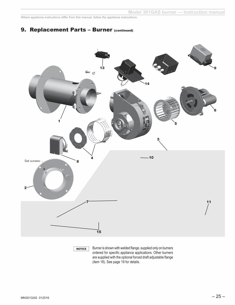
ITEM PART NO. DESCRIPTION
1
99259S 301/601Gas Airtube 14" B , 1" inlet for rates 401,000 to 700,000 BTU's.
99189S 301/601Gas Airtube 14" C , 1" inlet for rates 550,000 to 1,100,000 BTU's.
2 99225KITS Flange/Gasket kit for 301GAS/601GAS
399164S Combustion Head Assembly "B" Head
99277S Combustion Head Assembly "C" Head
4 99254S Airband/Air Shutter Kit
5 28563S Blower wheel/ fan
6 98611S Motor 1/6HP, 120V, 60HZ , 48N Frame
7 99158S Ignition Electrode/Flame Rod 301GAS
8 98521KITS Airflow switch and mounting plate assembly for 201/301/601GAS
9 60200FR343S Primary Control Microprocessor Flame Rod
10 99260S Gasket Kit (Includes 40253, 99260, 99430)
11 99162S Retention Ring Assy
12 30GFRWIRES Flame Rod Wire 24" for 301/601Gas (not shown)
13 99261KITS Door Interlock Switch and Mounting Screws
14 4180002S Ignitor for 301GAS
15 99153KITS Electrode/Flame Rod Bracket assembly
See Gas Train Wiring Supplement for parts breakdown and diagrams for all gas trains.
Model 301GAS burner — Instruction manual
MN301GAS 012516 – 25 –
Where appliance instructions differ from this manual, follow the appliance instructions.
9. Replacement Parts – Burner (continued)
Burner is shown with welded flange, supplied only on burners ordered for specific appliance applications. Other burners are supplied with the optional forced draft adjustable flange (item 18). See page 19 for details.
84
11
5
3
6
15
7
1
13
10
14
9
2

Model 301GAS burner — Instruction manual
MN301GAS 012516– 26 –
Where appliance instructions differ from this manual, follow the appliance instructions.


![1810 Federal Census · NORTON, Ifse 2 BOWLES, Evan 6 CARLIN, Alexis French/Kouri-Vini 5 CARLIN, Honoré 12 CARLIN, Célestin 6 CARLIN, Denis 7 CARLIN, Widow [of] 2 CARLIN, Eugêne](https://static.fdocuments.in/doc/165x107/5e6b107934ce1567772964a1/1810-federal-census-norton-ifse-2-bowles-evan-6-carlin-alexis-frenchkouri-vini.jpg)