![CUBE-BL-JP-18 CUBE-PK-JP-18 CUBE-YL-JP-18 (JP) …...CUBE-BL-JP-18 CUBE-PK-JP-18 CUBE-YL-JP-18 (JP) 1.2 Litre Capacity [JP] Operating Guide (JP)Please read this entire guide before](https://static.fdocuments.in/doc/165x107/5f0aa9a57e708231d42cb922/cube-bl-jp-18-cube-pk-jp-18-cube-yl-jp-18-jp-cube-bl-jp-18-cube-pk-jp-18-cube-yl-jp-18.jpg)
Installation and User's Manual for Cube Ice Machine Model … Manuals/User_man_CU50… ·...
16
Installation and User's Manual for Cube Ice Machine Model CU50
Transcript of Installation and User's Manual for Cube Ice Machine Model … Manuals/User_man_CU50… ·...

Installation and
User's Manual for
Cube Ice Machine
Model CU50

Introduction:
This ice machine is the result of Scotsman’sdecades of experience as an industry leader in thedesign and manufacture of both commercial andresidential ice machines.
This manual includes the information needed toinstall, start up and maintain the ice machine. Noteany Caution or Warning indicators, as they providenotice of potential hazards. Keep this manual forfuture reference.
March 2010Page 1
CU50Installation and User's Manual
Table of Contents
Specifications . . . . . . . . . . . . . . . . . . . . . . . . . . . . . . . . . . . . . . . . . . Page 2
Cabinet Layout . . . . . . . . . . . . . . . . . . . . . . . . . . . . . . . . . . . . . . . . . Page 3
Air flow & Control Panel . . . . . . . . . . . . . . . . . . . . . . . . . . . . . . . . . . . . . Page 4
Water Quality . . . . . . . . . . . . . . . . . . . . . . . . . . . . . . . . . . . . . . . . . . Page 5
Door swing change . . . . . . . . . . . . . . . . . . . . . . . . . . . . . . . . . . . . . . . Page 6
Notes for the Installer . . . . . . . . . . . . . . . . . . . . . . . . . . . . . . . . . . . . . . Page 7
Installation: Water & Drain . . . . . . . . . . . . . . . . . . . . . . . . . . . . . . . . . . . Page 8
Gravity Drain . . . . . . . . . . . . . . . . . . . . . . . . . . . . . . . . . . . . . . . . . . Page 9
Electrical . . . . . . . . . . . . . . . . . . . . . . . . . . . . . . . . . . . . . . . . . . . . Page 10
Start Up . . . . . . . . . . . . . . . . . . . . . . . . . . . . . . . . . . . . . . . . . . . . . Page 11
Use . . . . . . . . . . . . . . . . . . . . . . . . . . . . . . . . . . . . . . . . . . . . . . . Page 12
How to clean the condenser and winterize. . . . . . . . . . . . . . . . . . . . . . . . . . . . Page 13
Clean and Sanitize Ice Making System . . . . . . . . . . . . . . . . . . . . . . . . . . . . . Page 14
What to do before calling for service . . . . . . . . . . . . . . . . . . . . . . . . . . . . . . Page 15
Outdoor Use Notice:
Keep from freezing. Severe damage will occur to the unit if left in or operated in temperatures beyondthe limits listed in this manual. That damage is NOT covered by warranty.
Keep dry. Do not locate in low lying areas where puddles will accumulate.
Provide Shade: Heat gain from the sun will reduce the unit's ability to make and store ice, andultraviolet radiation from the sun can potentially damage the unit's plastic components.
Water Supply: Avoid a long run of hose or tubing exposed to the sun. Plastic water supply tubingshould be rated for potable water and include UV protection. Copper tubing is recommended.
Back Flow Prevention: The unit includes back flow prevention, no additional check valve is required.
Drainage: Do Not drain into swimming pool or onto grounds.
Operation: It is normal for the ice level in the storage bin to be low when unit is used in temperaturesbelow 65 degrees F.

Specifications
This ice machine is designed to be used indoors, ina controlled environment, and under limitedconditions (see page 1), outdoors. It can be used ina wide variety of environmental conditions, butthere are limits. Use outside of the listed limitationsis misuse and will void the warranty.
Air temperature limits:
The ice machine will operate adequately within thelimits, but functions best in temperatures between70 and 80 degrees F.
• Minimum – 50 degrees F. (10oC)
• Maximum – 100 degrees F. (38oC)
Water temperature limits:
• Minimum – 40 degrees F. (4.5oC)
• Maximum – 100 degrees F. (38oC)
Water pressure limits:
• Minimum – 20 psi (1.4 bar)
• Maximum – 80 psi (5.5 bar)
Because the ice machine is making a food product,the water supply to the ice machine must bepotable, or fit for human consumption.
Other:
Indoor use and kickplate: You may remove thestainless steel kickplate cover from the unit wheninstalled indoors. Leave the plastic kickplate on theunit.
Note:The stainless steel kickplate cover mustremain on the unit when the unit is installedoutdoors.
Electrical voltage limits:
• Minimum - 104 volts
• Maximum – 126 volts
Models
• CU50GA-1A - gravity drain
• CU50PA-1A - pump drain
Options:
Kickplate Extension: In some situations the leglevelers will be extended enough to become visible.
A kit to extend the kickplate over the legs is KKPF.
Cabinet Stability: In some free standinginstallations it may be prudent to add a bracket thatsecures the back of the cabinet to a wall. That kit
number is KATB.
Drain Conversion: A gravity drain model can beconverted to a drain pump model by installing adrain pump kit. The drain pump kit consists of adrain pump, wiring harness and associated tubing.
The part number is A39462-021.
Warranty Information
Warranty information is supplied separately fromthis manual. Refer to it for coverage. In general, thewarranty covers defects in materials orworkmanship and does not cover corrections ofinstallation errors or maintenance.
Service
This is a commercial product. If service is neededon a unit in a residence, use a commercial servicecompany. Locate one at www.scotsman-ice.com.
August 2014Page 2
CU50Installation and User's Manual
Cabinet Dimensions
Width Depth, with door panel, handle adds 1 5/8" Height
14 7/8" 22 3/4" 33 3/8" to 34 3/8"
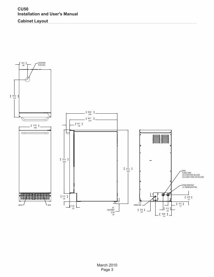
Cabinet Layout
March 2010Page 3
CU50Installation and User's Manual
1.00
LEGADJUSTMENT
[25.40]
14.88377.95
AIR OUT AIR IN
3.8898.55
17.45443.23
FLOOR DRAINACCESS HOLE
34.38873.25
3.8597.79
29.66753.24
22.29566.17
23.89606.68
1.6040.51
3.2081.28
3.2782.99
2.4462.04
1.5739.75
7.44188.98
3.8397.16
115 VPOWER CORD
POTABLE WATER INLET1/4" COMPRESSION FITTING
DRAINFLEXIBLE TUBING3/8 I.D. PUMP MODEL (INCLUDED)5/8 I.D. GRAVITY MODEL (NOT INCLUDED)
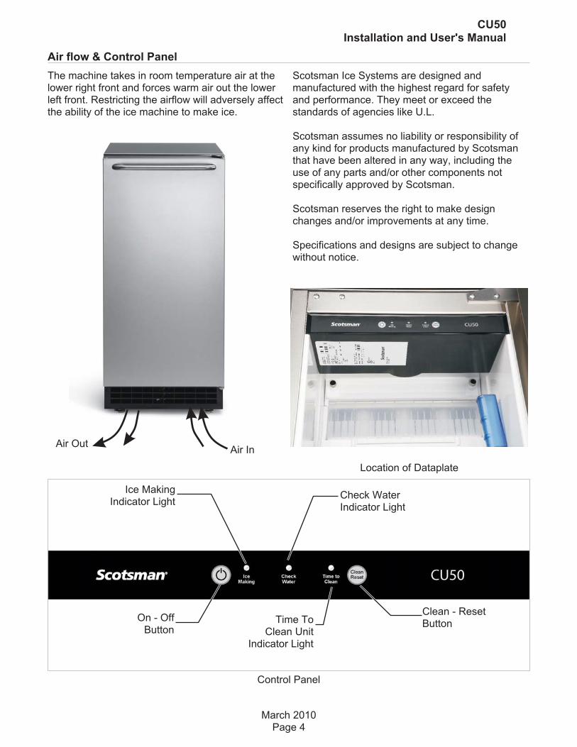
Air flow & Control Panel
The machine takes in room temperature air at thelower right front and forces warm air out the lowerleft front. Restricting the airflow will adversely affectthe ability of the ice machine to make ice.
Scotsman Ice Systems are designed andmanufactured with the highest regard for safetyand performance. They meet or exceed thestandards of agencies like U.L.
Scotsman assumes no liability or responsibility ofany kind for products manufactured by Scotsmanthat have been altered in any way, including theuse of any parts and/or other components notspecifically approved by Scotsman.
Scotsman reserves the right to make designchanges and/or improvements at any time.
Specifications and designs are subject to changewithout notice.
March 2010Page 4
CU50Installation and User's Manual
Control Panel
On - OffButton
Ice MakingIndicator Light
Check WaterIndicator Light
Clean - ResetButtonTime To
Clean UnitIndicator Light
Location of Dataplate
Air OutAir In
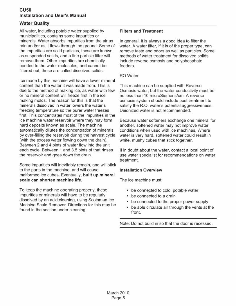
Water Quality
All water, including potable water supplied bymunicipalities, contains some impurities orminerals. Water absorbs impurities from the air asrain and/or as it flows through the ground. Some ofthe impurities are solid particles, these are knownas suspended solids, and a fine particle filter willremove them. Other impurities are chemicallybonded to the water molecules, and cannot befiltered out, these are called dissolved solids.
Ice made by this machine will have a lower mineralcontent than the water it was made from. This isdue to the method of making ice, as water with fewor no mineral content will freeze first in the icemaking molds. The reason for this is that theminerals dissolved in water lowers the water’sfreezing temperature so the purer water freezesfirst. This concentrates most of the impurities in theice machine water reservoir where they may formhard deposits known as scale. The machineautomatically dilutes the concentration of mineralsby over-filling the reservoir during the harvest cycle(with the excess water flowing down the drain).Between 2 and 4 pints of water flow into the uniteach cycle. Between 1 and 3.5 pints of that rinsesthe reservoir and goes down the drain.
Some impurities will inevitably remain, and will stickto the parts in the machine, and will cause
malformed ice cubes. Eventually, built up mineral
scale can shorten machine life.
To keep the machine operating properly, theseimpurities or minerals will have to be regularlydissolved by an acid cleaning, using Scotsman IceMachine Scale Remover. Directions for this may befound in the section under cleaning.
Filters and Treatment
In general, it is always a good idea to filter thewater. A water filter, if it is of the proper type, canremove taste and odors as well as particles. Somemethods of water treatment for dissolved solidsinclude reverse osmosis and polyphosphatefeeders.
RO Water
This machine can be supplied with ReverseOsmosis water, but the water conductivity must beno less than 10 microSiemens/cm. A reverseosmosis system should include post treatment tosatisfy the R.O. water’s potential aggressiveness.Deionized water is not recommended.
Because water softeners exchange one mineral foranother, softened water may not improve waterconditions when used with ice machines. Wherewater is very hard, softened water could result inwhite, mushy cubes that stick together.
If in doubt about the water, contact a local point ofuse water specialist for recommendations on watertreatment.
Installation Overview
The ice machine must:
• be connected to cold, potable water
• be connected to a drain
• be connected to the proper power supply
• be able circulate air through the vents at thefront.
Note: Do not build in so that the door is recessed.
March 2010Page 5
CU50Installation and User's Manual

Door swing change
The door can be attached to open with hinges onthe left or right.
To change:
1. Remove top hinge pin from hinge.
2. Tilt top of door away from cabinet and lift dooroff bottom hinge.
3. Remove two screws and top hinge.
4. Remove plugs or screws from lower cabinetbracket
5. Attach top hinge to lower cabinet bracket usingoriginal screws.
6. Remove original bottom hinge.
7. Remove two plugs or screws from uppercabinet bracket.
8. Attach bottom hinge to upper cabinet bracketusing the original screws.
9. Place the door on bottom hinge, tip up to slideunder top hinge.
10. Insert hinge pin into top hinge and door.
11. Tighten hinge pin.
12. Replace screws or plugs into holes left byhinges.
13. Check action and swing of door.
March 2010Page 6
CU50Installation and User's Manual

Notes for the Installer
Sealing to floor: In some cases the base of the icemachine must be sealed to the floor to meet localcode. Food grade silastic sealant such asScotsman part number 19-0529-01 isrecommended.
Place the machine in the intended location. Turnthe leg levelers in until the bottom of the unit is asclose to the floor as possible. Be sure the unit islevel and all four levelers are in contact with thefloor.
Place a bead of the sealant between the floor andthe outside edge of the cabinet. The bead must fillthe space between the cabinet bottom edges andthe floor.
Installations on a slab: Use a pump model andpump the water to the point of drainage. Pumpmodels will pump 1 story (10 feet) high.
Installations over a crawl space or basement:Either gravity drain or pump model units may beused, if there is not enough room behind themachine for a drain/waste receptacle, the drain willhave to be below the floor.
Note: When installed in a corner, the door swingmay be limited due to handle contact with the wallor cabinet face.
March 2010Page 7
CU50Installation and User's Manual

Installation: Water & Drain
The recommended water supply tubing is ¼ inchOD copper. Install an easily accessible shut-offvalve between the supply and the unit. This shut-offvalve should not be installed behind the unit.
Note: Do not use self-piercing type valves.
1. Remove the front service panel.
2. Route the tubing through the right hole in theback to the inlet water solenoid valve inlet.
3. Install a compression fitting on the tubing andconnect to the inlet of the solenoid.
Drains
There are two types of ice machine models, onethat drains by gravity and one that has an internaldrain pump.
Drain Pump Model drain installation
1. Locate the coil of 3/8” ID plastic drain tubingsecured to the back of the unit.
2. Route the plastic drain tube from the back of theunit to the drain connection point.
The drain connection point can be as high as 10feet above the ice machine. The drain pumpincludes a check valve to prevent re-pumping waterin the drain hose.
IMPORTANT NOTE: Often an air gap is required bylocal codes between the ice maker drain tube andthe drain receptacle.
March 2010Page 8
CU50Installation and User's Manual
ScrewSecuring
Front ServicePanel
Water Connection Point

Gravity Drain
Caution: Restrictions in the drain system to themachine will cause water to back up into the icestorage bin and melt the ice. Gravity drain tubingmust be vented, have no kinks and slope to thebuilding drain. Air gaps are typically required bylocal code.
1. Place the ice machine in front of the installationopening. Adjust leveling legs to the approximateheight.
2. Remove the front service access panel and theupper back panel.
Note: If you are connecting a gravity drain modeland the drain opening has been located in the floorunder the base pan according to the pre installspecifications, follow steps 3 through 5 to drain theunit through the base. If not, proceed to step 6b.
3. Remove the clamp and barbed elbow and takeoff the plastic cover in the base pan below the drainhose.
4. Connect a straight 5/8” barbed connector to thedrain hose, securing with the clamp removed instep 3.
5. Cut an 8” piece of 5/8” ID X 7/8” OD tygon (clearplastic) tubing. Slide one end of the tube onto the
outlet of the barbed connector and secure with aclamp. Leave the other end of the tube lying on thefloor of the base pan until the unit is positionedover the floor drain.
6. Route the drain tube. Either a) Insert the draintube through the base pan into the floor drain or b)Route the drain tube through the left hole in thelower back panel and connect to barbed elbow andsecure with a clamp.
Note: Add a vertical vent in a horizontal drain tubeto reduce internal pressure and improve drainage.
7. Reinstall the upper back panel.
8. Reinstall the service access panel. Level theunit.
March 2010Page 9
CU50Installation and User's Manual
Back View, Drain Pump Model
Water InletTube (fieldsupplied)
Drain Tube,Route to
building drain

Electrical
The ice machine is supplied with a power cord. Donot remove the grounding pin from the cord’s plug.Do not use extension cords. Follow all codes.Connect the machine to its own 115 volt, 15 ampcircuit.
1. If the electrical outlet for the ice maker isbehind the unit, plug in the unit.
2. Position the unit in the installation opening.
3. Turn on the water supply. Make sure that theice maker is plugged in and the power is on.
4. Slide unit into installation opening, payingcareful attention to water supply and drainconnections. Do not kink!
5. Pour a couple of quarts of water into the icestorage bin; on drain pump equipped machinesthe drain pump should start and water shouldpump out. Check for leaks.
6. Replace the service access panel.
7. Level the unit as needed.
March 2010Page 10
CU50Installation and User's Manual
Back View, Gravity Drain Model
Water InletTube (fieldsupplied)
Drain HoseBarbed Elbow
Drain Hose,Route tobuilding drain
Start Up
Check list:
1. Has the unit been connected to the properwater supply?
2. Has the water supply been checked for leaks?
3. Has the unit been connected to a drain?
4. Has the drain been tested for flow and leaks?
5. Has the unit been connected to the properelectrical supply?
6. Has the unit been leveled?
7. Have all packing materials been removed fromthe machine?
8. Has the door covering been installed?
Initial Start Up
1. Turn on the water supply.
2. Switch on the electrical power.
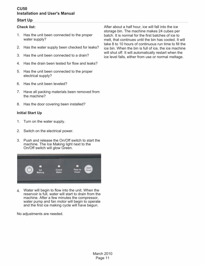
3. Push and release the On/Off switch to start themachine. The Ice Making light next to theOn/Off switch will glow Green.
4. Water will begin to flow into the unit. When thereservoir is full, water will start to drain from themachine. After a few minutes the compressor,water pump and fan motor will begin to operateand the first ice making cycle will have begun.
No adjustments are needed.
After about a half hour, ice will fall into the icestorage bin. The machine makes 24 cubes perbatch. It is normal for the first batches of ice tomelt, that continues until the bin has cooled. It willtake 8 to 10 hours of continuous run time to fill theice bin. When the bin is full of ice, the ice machinewill shut off. It will automatically restart when theice level falls, either from use or normal meltage.
March 2010Page 11
CU50Installation and User's Manual

Use
No special instructions are needed for use. Justtake as much ice as you need, the machine willreplace it. A scoop is provided, and it can be storedin the machine using the loop of tubing on the rightside as a holder. That tubing is also the ice levelsensor; ice will fill the storage bin until it's near to oron that tube and then the machine will shut off.
To maximize ice storage capacity, you may need touse the scoop to level the ice in the storage bin,especially within the first day or so of operation.
The machine can be shut off anytime by justpushing and releasing the On/Off button. Themachine will shut off at the end of the next cycle.To shut off immediately, push and hold the On/Offbutton in until the machine stops.
What shouldn’t be done?
Never keep anything in the ice storage bin that isnot ice. Objects like wine or beer bottles are notonly unsanitary, but the labels can slip off and plugup the drain.
Never allow the machine to operate without regularcleaning. The machine will last longer if it is keptclean. Regular cleaning should happen at leastonce per year, and preferably twice. Some waterconditions will dictate even more frequent cleaningof the ice making section, and some carpets orpets will dictate more frequent cleaning of thecondenser.
Note: The Time to Clean light will switch ON after 6months of use. It will stay ON until the ice makingsystem is cleaned using the process on page 13.
Noise:
The ice machine is designed for quiet operation,but will make some noise during the ice makingcycle. During a freezing cycle, it is normal to hearthe fan moving air and the water pump circulatingwater. Ice hitting the bin or ice in the bin can beheard during harvest.
Maintenance
There are 5 things to keep clean:
1. The outside cabinet & door.
2. The ice storage bin.
3. The condenser.
4. The ice making system.
5. The ice scoop.
How to clean the cabinet.
Wipe off any spills on the surface of the door andhandle as they occur. If anything spilled on thedoor or gasket dries onto the surface, wash withsoap and warm water to remove.
How to clean the ice storage bin.
The ice storage bin should be sanitizedoccasionally. It is usually convenient to sanitize thebin after the ice making system has been cleaned,and the storage bin is empty.
A sanitizing solution can be made of 1 ounce ofhousehold bleach and two gallons of hot (95
oF. –
115oF.) water. Use a clean cloth and wipe the
interior of the ice storage bin with the sanitizingsolution, pour some of the solution down the drain.
Allow to air dry.
March 2010Page 12
CU50Installation and User's Manual
Normal cubes are tapered cylinders. If the cubesare ragged and mis-shaped, mineral scale must be
removed from the ice making system

How to clean the condenser and winterize.
Condenser cleaning
The condenser is like the radiator on a car, it hasfins and tubes that can become clogged with dirtand lint. To clean:
1. Remove the kickplate and front service panel.
Note: Outdoor operation can lead to rapid build upof debris, such as leaves and other vegetation. Thecondenser will need to be frequently checked fordebris. Clean it whenever the fins are obstructed.
2. Locate the condenser surface.
3. Vacuum the surface, removing all dust and lint.
Caution: Do not dent the fins.
4. Return the kickplate and front service panel totheir original positions. Fasten them to the cabinetusing the original screws.
Winterizing
1. Clean the ice making system.
2. Open the door and push and release the On/Offswitch to turn the machine off.
3. Turn off the water supply.
4. Drain the water reservoir by removing the rubbercap under the reservoir - it's near the back wall ofthe ice storage bin.
5. Disconnect the incoming water line at the inletwater valve.
6. Open the door, push and release the on/offswitch to turn the machine on.
7. Blow air through the inlet water valve until waterstops flowing out; a tire pump could do the job.
8. Drain pump models should have about 1/2gallon of RV antifreeze (propylene glycol) pouredinto the ice storage bin drain.
Note: Automotive antifreeze must NOT be used.
9. Switch off and unplug the machine.
March 2010Page 13
CU50Installation and User's Manual
Rubber Cap
CondenserSurface

Clean and Sanitize Ice Making System
Remove Scale
1. Remove and discard all ice.
2. Press and HOLD the On/Off button in for 3seconds until the Green light goes out.
3. Press and HOLD the both the Clean-Reset andOn/Off buttons for 5 seconds. The Time to Cleanlight will blink on and off.
4. Pour 8 ounces of Scotsman Ice Machine ScaleRemover (available from a local ScotsmanDistributor or Dealer) into the ice machinereservoir.
5. Operate the machine for about ½ hour.
6. Push and release the On/Off switch. Themachine will begin to flush out the cleaningsolution.
7. Operate the machine for another ½ hour.
8. Push and release the On/Off switch. Themachine will stop the cleaning process.
9. Pour a gallon of hot (95oF. – 115
oF.) water into
the bin to flush out the drain.
10. Clean the bin liner of mineral scale by mixingsome ice machine scale remover and hot water,and using that solution to scrub the scale off of theliner.
11. Rinse the liner with hot water.
Sanitize the bin interior.
1. Mix a 1 gallon solution of locally approvedsanitizer.
Use an EPA approved food equipment sanitizer atthe solution mix recommended by the sanitizermanufacturer.
2. Remove the top panel.
3. Pour 2 quarts of sanitizer solution onto the top ofthe ice making platen. Be sure all surfaces insidethe platen are contacted by the sanitizer.
4. Return the top panel to its original position.
5. Remove the curtain, wash it with the sanitizingsolution. Return the curtain to its original position.
6. Press and HOLD the both the Clean-Reset andOn/Off buttons for 5 seconds. The Time to Cleanlight will blink on and off.
7. Thoroughly wash all surfaces of the reservoir,bin liner, scoop, scoop holder and door liner withthe sanitizer solution. Pour excess solution into binto sanitize the drain.
8. Wait 10 minutes, push and release the On/Offswitch. The machine will begin to flush out thesanitizing solution.
9. Operate the machine for another ½ hour.
10. Push and release the On/Off switch. Themachine will stop the cleaning process.
11. Push and release the On/Off switch again torestart ice making.
June 2012Page 14
CU50Installation and User's Manual
Pour ScaleRemover Here

What to do before calling for service
Ice cubes are incompletely formed
• Clean the ice making system
Low capacity
• Check for restricted drain or standing waterin the bin
• Clean the air cooled condenser fins
No ice
• Check on-off switch
• Check electrical breaker
• If the Check Water light is flashing Red,check water supply. The control systemchecks for water every 20 minutes. When thewater supply is restored, the machine willautomatically restart ice making.
• If outdoors and the air temperature is below50 degrees F., the machine may not operate.
Time to Clean light is on
• Clean the ice making system.
SCOTSMAN ICE SYSTEMS
775 Corporate Woods Parkway, Vernon Hills, IL 60061
800-533-6006
www.scotsman-ice.com
17-3314-01