
InRoads SS2 Survey Database QA Guide for Consultants · InRoads SS2 Survey Database QA Guide for...
18
InRoads SS2 Survey Database QA Guide for Consultants This guide is provided, along with the Survey Data Processing InRoads QA Checklist, to assist Consultants in performing Quality Assurance on survey databases prior to submitting to GDOT for review. Consultants are required to use this guide, along with the Checklist, to ensure any issues discovered are corrected prior to submittal to GDOT. If some of these critical tasks are not properly performed, the database will not be reviewed and the consultant will be directed to go through this guide and resubmit. This guide is an effort to standardize the review process and reduce the number of resubmissions. Any comments or concerns that come up during the QA of the first submission need to be entered into the Comments section at the end of the Survey Data Processing InRoads QA Checklist. For example, if the project was surveyed in 2012, then the current requirement of having accurate elevations on all points may not apply and you should enter the date of the survey in the comments section to explain why it does not meet this current standard. This will facilitate a quicker approval process. Before you begin, ensure you are using the latest GDOT Customization files for both InRoads SS2 and MicroStation V8i from the GDOT ROADS webpage. Task #1: Check the DTM File Properties Right click the Surface/DTM file inside InRoads and select Properties. Under the Main tab check to make sure the maximum length is 300.000 Check that Lock Triangulation is unchecked Under the Advanced tab of the Surface Properties, make sure “EXISTING” is the selected symbology option for both Cross Sections as well as Profiles. LOCK TRIANGULATION SHOULD BE UNCHECKED
Transcript of InRoads SS2 Survey Database QA Guide for Consultants · InRoads SS2 Survey Database QA Guide for...
InRoads SS2 Survey Database QA Guide for Consultants
This guide is provided, along with the Survey Data Processing InRoads QA Checklist, to assist Consultants in performing Quality Assurance on survey databases prior to submitting to GDOT for review. Consultants are required to use this guide, along with the Checklist, to ensure any issues discovered are corrected prior to submittal to GDOT. If some of these critical tasks are not properly performed, the database will not be reviewed and the consultant will be directed to go through this guide and resubmit. This guide is an effort to standardize the review process and reduce the number of resubmissions. Any comments or concerns that come up during the QA of the first submission need to be entered into the Comments section at the end of the Survey Data Processing InRoads QA Checklist. For example, if the project was surveyed in 2012, then the current requirement of having accurate elevations on all points may not apply and you should enter the date of the survey in the comments section to explain why it does not meet this current standard. This will facilitate a quicker approval process.
Before you begin, ensure you are using the latest GDOT Customization files for both InRoads SS2 and MicroStation V8i from the GDOT ROADS webpage.
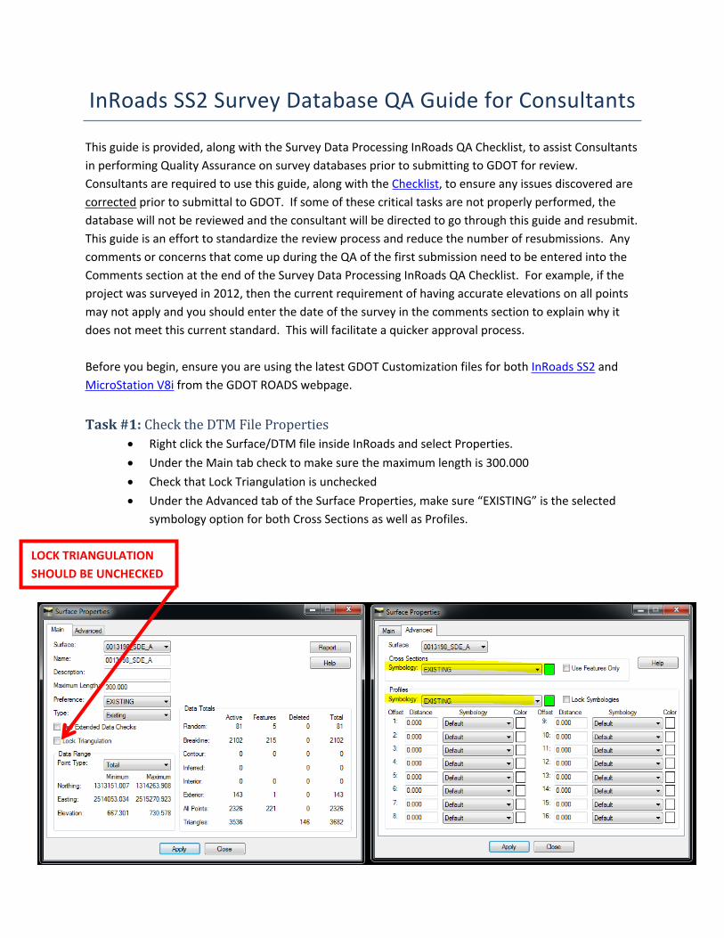
Task #1: Check the DTM File Properties Right click the Surface/DTM file inside InRoads and select Properties. Under the Main tab check to make sure the maximum length is 300.000 Check that Lock Triangulation is unchecked Under the Advanced tab of the Surface Properties, make sure “EXISTING” is the selected
symbology option for both Cross Sections as well as Profiles.
LOCK TRIANGULATION SHOULD BE UNCHECKED

Task #2: Check File NamesCheck both the internal as well as external file names for both the ALG and DTMs submitted. The file names should be identical between the internal and external file names and should be as follows: PI#_SDE. If there are multiple DTM or ALG files, these should be differentiated by a letter at the end of the file name. As long as it’s clearly differentiated, that is what matters. For example, 1234567_SDE-A.DTM and 1234567_SDE-B.DTM are as equally acceptable as 1234567_SDE_A.DTM & 1234567_SDE_B.DTM.
Task #3: Use Feature Filters to find and correct errorsIf you do not have the Feature Filter toolbar active, then go to Tools>Locks and ensure there is a check next to Toolbar. This is very helpful and will shorten your review.

Do not change or customize any parameters of features, such as Feature Type or whether it is triangulated or not. The single exception to this rule is for the exterior boundary, where the feature style TOPO_E_TLIML is a breakline by default (this needs to be set to an exterior feature type). If you need a feature to be something different than what GDOT has provided, then you should choose an appropriate survey-defined feature style (point or chain, triangulate or not) and include a description so that end users know what the feature represents. GDOT has set up several feature filters that allow you to find errors easily and quickly. These must be resolved prior to submitting to GDOT and are explained in detail below.
GDOT Feature Filters: Breaklines (should be Random): finds all features that have a Feature Type of Breakline, but
according to the Feature Style used should instead be Random. These features either need to be changed to be a Random Feature Type (if the Feature Style used was correct), or else assigned an appropriate GDOT Feature Style. If no appropriate Feature Style is provided by GDOT for the feature (i.e. mailboxes), then use an appropriate Survey-Defined Feature Style and provide a description so that users know what this feature is.
Random (should be Breaklines): finds all features that have a Feature Type of Random, but according to the Feature Style used should instead be Breakline. These features either need to be changed to be a Breakline Feature Type (if the Feature Style used was correct), or else assigned an appropriate GDOT Feature Style. If no appropriate Feature Style is provided by GDOT for the feature (i.e. mailboxes), then use an appropriate Survey-Defined Feature Style and provide a description so that users know what this feature is.
OldFeatureStylesNotInUse: finds all features that use Feature Styles that are no longer accepted by GDOT. They are only still available for backwards compatibility. Check the InRoads Field Survey Feature Codes document for a list of current GDOT feature styles and choose one off of this list.
Survey_Control_Deltas: finds all features that are Survey Control Delta points (all points using the feature styles TOPO_E_SBNCHMK, TOPO_E_SCCHK, TOPO_E_SDCD, TOPO_E_SLCD, TOPO_E_SLCM, or TOPO_E_SNGSCM). If no features are found with this filter, then that means that you have not included them in the DTM and need to do so.
Triangulate=NO (should be YES): finds all features that do not triangulate, but should be, according to the feature style used. These features either need to be changed so that they are set to triangulate (if the Feature Style used was correct), or else assigned an appropriate GDOT Feature Style. If no appropriate Feature Style is provided by GDOT for the feature (i.e. mailboxes), then use an appropriate Survey-Defined Feature Style and provide a description so that users know what this feature is.
Triangulate=YES (should be NO): finds all features that triangulate, but should NOT be, according to the feature style used. These features either need to be changed so that they are excluded from triangulation (if the Feature Style used was correct), or else assigned an appropriate GDOT Feature Style. If no appropriate Feature Style is provided by GDOT for the feature (i.e. mailboxes), then use an appropriate Survey-Defined Feature Style and provide a description so that users know what this feature is.

UtilityFeatureStylesUsingTOPO: finds all of the utility features that are using the older Utility feature styles that begin with TOPO_E, which are no longer accepted by GDOT and are only still available for backwards compatibility. All Utility feature styles now begin with UTLE_E, not TOPO_E, and any found using this filter need to be changed to the current accepted feature styles for Utilities.
Non_Standard_Features: finds any features that use feature styles that are not part of GDOT’s Standard list of available Feature Styles. Any features found using this filter need to be changed to utilize accepted GDOT Feature Styles., which can be found in the InRoads Field Survey Feature Codes document. This filter will also find any features using the PROP_E Feature Styles, which should not be in the DTM and need to be removed and/or added to the ALG file instead (or changed to the appropriate Feature Style if they were designated with incorrect Feature Styles).
To use these filters, simply open the Feature Properties dialogue: Surface>Feature>Feature Properties.

With the Feature Properties window open and the Feature Filter turned ON, you can now toggle between each of the above filters to find potential errors.
Select each of the filters listed previously, one at a time. If you find ANY features listed in the Feature Properties window while using an active Feature Filter listed above, then that is an error that you need to correct. The one exception is the Survey_Control_Deltas filter. This filter finds the Survey Control Deltas, so in this case, if you do NOT have any features listed in the Feature Properties window, then that means you have none and need to add them to the DTM.
Feature Filter can be toggled on/off here
Filter list pulldown

If you need to make a change to a large group of features with the same Feature Style, the quickest way to do so is to click the Style heading to sort by feature styles in ascending or descending order. Then, you can select all of the features in the group at one time by highlighting the first feature, holding down the Shift key, and then selecting the last feature in the list. Then, simply make the required change/s (i.e. adding a description, changing triangulation, feature style, feature type, etc.) and click Apply. Remember to re-triangulate and save the DTM if any triangulation was changed.
Task #4: Add descriptions to all Survey-Defined FeaturesCheck all features, both TOPO as well as UTILITY, that use Survey-Defined Feature Styles (i.e. UTLE_E_UXXA, TOPO_E_XXQ, etc.). Ensure that all of them have descriptions so that users know what they represent. Avoid using acronyms or abbreviations that may not be understood by all users. Also ensure that there is not a more appropriate Feature Style available to use instead of Survey-Defined.
Task #5: Elevations required on all points Ensure that all points/features in the DTM have valid, accurate elevations, even features that do not triangulate. Please see section 2.26 of the Survey Manual for details. For features that are not able to be located accurately (i.e. a buried invert of a pipe, underground utility feature, etc.), estimate the elevation as accurately as possible and add “ESTIMATED ELEV” to the descriptions. Revise any point/feature elevations that are erroneous, even those that are excluded from triangulation.

Task #6: Bridges and Drainage Structures Ensure that all bridges are defined as detailed in Chapter 4 of the GDOT Automated Survey
Manual. Page 4-38 of this manual has a summary of what Feature Styles to use on a bridge, but is not all-encompassing. Ensure all required items are included, such as centers of columns, bottoms of bridge beams, stream traverses, etc. and that all items are assigned the correct Feature Styles.
Ensure that all catch basins, culverts, headwalls and wingwalls have been defined as detailed in the GDOT Automated Survey Manual, section 3.4 (pg. 3-7). One common mistake is using Feature Style TOPO_E_DCB for the manhole cover top. Do not do this. TOPO_E_DCB is ONLY for the throat of the catch basin, along the gutter flow line, which you should be picking up. For manhole cover tops on catch basins and storm drains, use feature style TOPO_E_UMHST. All other manhole cover tops (telephone, electrical, sanitary sewer, etc.) have their own unique Feature Styles and are considered Utility Features, whereas storm drain manholes are not.
Task #7: CSV file Survey DeliverableIn order to facilitate a quicker and easier transition to the latest version of civil design software, Open Roads Designer (ORD), GDOT requires a CSV file deliverable that includes all points/chains with each submission. This will allow any survey performed for InRoads SS2 to easily be imported into a Field Book, if needed, for use in ORD. An example of a properly-formatted CSV file is shown below. Do not include a header row; just the data, as shown in the example below.
There are four survey Link Codes used by GDOT. You can see “ST” used in a few chains in the example below. The Link Codes are:ST = Start Chain CL = Close Chain PC = Begin Curve PT = End Curve
These CSV files should be named PI#_Submission#.CSV (i.e. 0001648_Submission1.csv.
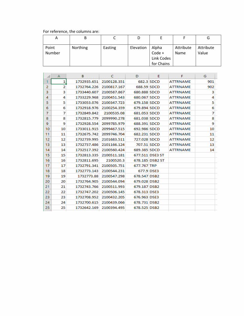
For reference, the columns are:A B C D E F G
Point Number
Northing Easting Elevation Alpha Code + Link Codes for Chains
Attribute Name
Attribute Value

Task #8: Resolve Crossing SegmentsFrom the InRoads Menu Bar select Surface > Utilities > Resolve Crossing Segments. Change the Mode from Automatic to Interactive, set the Delta Tolerance to < 0.020 and click Apply. If a feature is listed, paired with either an XBOUNDARY or an MBOUNDARY (the exterior boundary), and the delta is 0.000, then it is acceptable; otherwise, it must be resolved. Scroll through the entire list for Crossing Segments that do not involve the exterior boundary (even those with an elevation delta of 0.000). If you have some crossing segments that are scattered amongst many acceptable crossing segments along an exterior boundary and need to resolve them, you can filter out the acceptable ones by using the Feature Filter Crossing Segment Finder. If you are unsure, it’s best to go ahead and use this filter as a check. You have to click Apply again after selecting the Feature Filter in order to see the filtered results; if you just select the filter, nothing happens. You can resolve these Crossing Segments (< 0.020) by using the Mode: Automatic and Match Elevation: Median options, and then clicking Apply.
Repeat this entire step for a > 0.020 Delta Tolerance setting. However, any Crossing Segments you find over the 0.020 Delta Tolerance must be resolved manually using the Edit Surface tools in InRoads. Do not resolve these automatically.
New Crossing Segments can be created when you resolve one of them, so before submitting to GDOT, be sure to run the Surface > Utilities > Resolve Crossing Segments command again when you are done resolving them to make sure no new ones have been created.

Task #9: DTM Surface Checks Ensure that when you view the DTM Triangles (Surface > View Surface > Triangles), you do not get a message asking you to re-triangulate, or any other messages like the triangles being out of date. If you do, then fix the error and save the DTM so that it no longer displays any messages with this command. If you make any further updates to the DTM after this step that affect triangulation, you will need to resave it again to avoid getting this message.
With the DTM Triangles still in view, use the Microstation commands Fit, Rotate, Pan and Zoom as needed to look for spikes and other discrepancies in the DTM. Any obvious spikes are expected to be discovered and corrected prior to submitting to GDOT. The Microstation toolbox “View Control” has all of these commands:
After rotating the view, you can get back to Top View by left-clicking (and keeping it pressed down) on the Rotate button above, and then choose Top View from the selection choices.
Check for erroneous triangles in the DTM, particularly at intersections. This typically happens when the exterior boundary extends beyond where breaklines and TRP points exist. In this case, the exterior boundary needs to be tightened up to where the good survey data exists. Also, do not trim the erroneous triangles, as you see below; instead, move the boundary to where the good data exists. Trimming in this manner will present problems later on if the DTM is re-triangulated. Re-triangulate and resave the DTM if any changes are made. See example below, where some erroneous triangles and incorrect exterior boundaries appear on some quadrants.
RotateFit View
Zoom In/Out Pan

Task #10: Exterior and Interior BoundariesThere should only be one exterior boundary, which is a closed shape. The feature should have a feature style of TOPO_E_TLIML and be named either XBOUNDARY (for field surveys) or MBOUNDARY (for mapping projects). Be sure it is set to triangulate and has an exterior Feature Type as well.
Next, from the InRoads Menu Bar view the surface features by selecting the command Surface > View Surface > Features. Highlight only the exterior boundary (XBOUNDARY or MBOUNDARY) and any interior boundaries (any features using Feature Styles TOPO_E_DOBSC, TOPO_E_MOBSC, TOPO_E_TCBA, TOPO_E_TCBF, or TOPO_E_TLAKE) that may exist. Click Apply.
Select the exterior boundary (XBOUNDARY or MBOUNDARY) to highlight it and make sure no triangles are outside of it.
Ensure no triangles exist inside any of the interior boundaries and that the triangles also come all the way up to the features. There should be no gap between the edge of triangles and the border of the interior boundary.
Erroneous Triangles .gov/PS/DesignSoftware/Microstation
Boundary needs to be moved to where good survey data is.

Task #11: Pipe sizes and conditionsThis task is critical and for longer projects with a large amount of pipes, may take the most time of any of these tasks to QA. Check for pipes and culverts in the DTM (Feature Styles TOPO_E_DCEF, TOPO_E_DPC, TOPO_E_DPM & TOPO_E_DPP). If any exist, a size description is required (if known), in addition to pipe conditions/function on all cross drain pipes (as detailed in section 3.5 of the GDOT Automated Survey Manual). The elevations of all inverts in the DTM should be accurate and match exactly what is shown in the pipe annotation in the TOPO.DGN file. All pipes shown in the TOPO.DGN file must also be included in the DTM file. For pipes/culverts that cannot be located, you must estimate the elevation to the best of your ability and enter “ESTIMATED ELEV” in its description, as detailed on page 2-80 of the Survey Manual. GDOT often sees elevations or pipe materials entered in the TOPO.DGN file that do not match what is in the DTM. You are expected to check and fix these on your own. If GDOT notices several pipes with errors, we may elect to reject the submission and send it back for you to perform another QA and resubmit. In this case, you will not receive a detailed report of errors, but rather a general comment asking you to go back and check all pipe invert elevations/materials for congruency between these files.
Task #12: Compress DTMCompress the DTM by using the command Surface > Utilities > Compress Surface… and then save the DTM. It is easy to tell whether a DTM has been compressed or not. Simply click on the the Surface in the left pane of the InRoads window, and then look at the column labeled Deleted. If you see any numbers in this column other than zero (0) for any items other than Triangles, then that means that it has not been compressed. You can also see this Deleted column in the Surface Properties dialogue box.
Task #13: QA Checklist and CommentsA QA Checklist must be submitted with each submission. For first submissions, please enter any comments, questions or concerns you may have in the Comments section on the QA Checklist. This will facilitate fewer resubmissions.
For any resubmissions, it is preferred that you enter any comments instead directly on the QA Report received, if possible. This makes it easier for GDOT to reference. In any case, it is a requirement on any resubmissions that you provide comments in some form for each item that was addressed. Failure to provide comments could result in additional submissions (due to the reviewer not understanding how/why a change was made or not made) or in the worst case, a complete rejection and request for a resubmission.
Geometry/Property DataTask #14: Alignments
Verify that the ALG file has not been inadvertently altered to be a “read-only” file. GDOT receives this error frequently. To check for this, simply click on the ALG file in the left pane of InRoads, under Geometry Projects. Next, scroll down to view all alignments plus the Cogo Buffer, paying special attention to the column “Access Mode”. This should say “Read-Write” in all rows. If any of them say “Read-Only”, then that is an error that you need to resolve. See Appendix A below for how to resolve that error.
Check to make sure all of the alignments are assigned the correct feature style. “Default” Feature Style is unacceptable. PROP_E_POEL is not to be used for Easement alignments; use PROP_E_ESMT instead.
PROP_E_POEL can be used for points on the alignment, just not for the alignment chain. All Alignments have descriptions and an ‘SV’ prefix for the names (i.e. SV12).
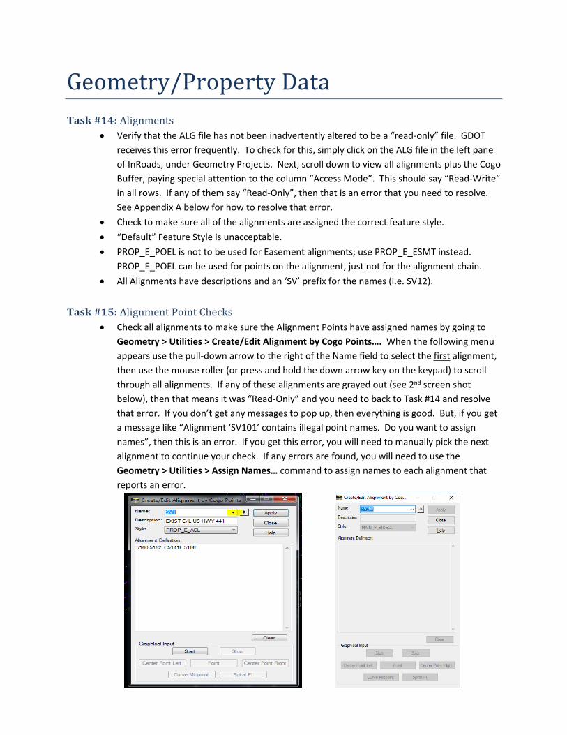
Task #15: Alignment Point Checks Check all alignments to make sure the Alignment Points have assigned names by going to
Geometry > Utilities > Create/Edit Alignment by Cogo Points…. When the following menu appears use the pull-down arrow to the right of the Name field to select the first alignment, then use the mouse roller (or press and hold the down arrow key on the keypad) to scroll through all alignments. If any of these alignments are grayed out (see 2nd screen shot below), then that means it was “Read-Only” and you need to back to Task #14 and resolve that error. If you don’t get any messages to pop up, then everything is good. But, if you get a message like “Alignment ‘SV101’ contains illegal point names. Do you want to assign names”, then this is an error. If you get this error, you will need to manually pick the next alignment to continue your check. If any errors are found, you will need to use the Geometry > Utilities > Assign Names… command to assign names to each alignment that reports an error.

Check to ensure that all assigned points on alignments have been converted to COGO points. To do this, use the Style Sheet GDOT COGO Point Validation to verify. Documentation for this Style Sheet should be located on your computer under C:\InRoads Data\Style Sheet Documentation\. Any Alignments reported here are errors and need to have their alignment points converted to COGO points.
Task #16: COGO Points Click the “+” button beside the geometry file name in the INROADS window to expand and
view the items in the file. Click on the Cogo Buffer and the Style column (both highlighted below) for the COGO points
to be visible and sorted in alphabetical order. Scroll down to ensure all points have proper Feature Styles assigned to them. Property corners and right of way monuments (PROP_E_PCF, PROP_E_RWM) should be
included, if found. PROP_E_PAR is not acceptable for points; it’s only used for parcel alignments. Check for survey control deltas (TOPO_E_SDCD, TOPO_E_SLCD, TOPO_E_SNGSCM, and
TOPO_E_SBNCHMK). Control Deltas should be included both the DTM and ALG files.
Task #17: Parcel Chain Check Go to Tools > XML Reports > Geometry and when the following window appears place the
cursor in the Include field under the Horizontal Alignments heading and click the Filter button.

When the following window appears click Preferences, select PROP_E_PAR, and click Load and then Close. This filters the alignments so that only those with the PAR feature style are visible.
Click the All Button to select the PAR chains and click OK.
When the following window appears click Apply.
Select GDOT Parcel Check Report.xsl in the following window:

In the Total Deflection and Parcel Acreage columns, look for any Parcel Chains that say “Counter-clockwise“ or “Not Closed”.
Any chains that were stored counter-clockwise will need to be re-stored in a clockwise manner. NOTE: If a curve is the 1st element in a chain it may erroneously report as counter clockwise even when it is clockwise. This can be resolved by using Check Integrity > Move Forward to move the curve so that it is the last element in the chain.
Any chains that are not closed must be closed, unless they are so large that they fall outside of the database. Any parcels that cannot be closed, due to lack of data, should be noted in your comments.
Check the PSR spreadsheet to ensure that the InRoads chain names are listed for each parcel alignment.
Task #18: ALG vs. PROP.DGN comparison View ALL Alignments in the ALG file. Change all elements to RED and a thicker weight so they stand out. Simply use the
Microstation command Edit > Select All and then use Change Element Attributes. Attach the Reference file PROP.DGN and then move the Reference file slightly so it is easy to
compare the Alignments. To do this, simply right click on the Reference File and select Move and then move the cursor to the desired location.
Move/pan/zoom around and ensure all alignments appear in both files. Add any alignments that are missing in either file, as needed.

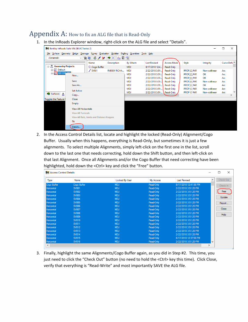
Appendix A: How to fix an ALG file that is Read-Only1. In the InRoads Explorer window, right-click on the ALG file and select “Details”.
2. In the Access Control Details list, locate and highlight the locked (Read-Only) Alignment/Cogo Buffer. Usually when this happens, everything is Read-Only, but sometimes it is just a few alignments. To select multiple Alignments, simply left-click on the first one in the list, scroll down to the last one that needs correcting, hold down the Shift button, and then left-click on that last Alignment. Once all Alignments and/or the Cogo Buffer that need correcting have been highlighted, hold down the <Ctrl> key and click the “Free” button.
3. Finally, highlight the same Alignments/Cogo Buffer again, as you did in Step #2. This time, you just need to click the “Check Out” button (no need to hold the <Ctrl> key this time). Click Close, verify that everything is “Read-Write” and most importantly SAVE the ALG file.