HIGH/LOW SPEED PRECISION PUMP
22
instrumentation and software for research HIGH/LOW SPEED PRECISION PUMP PHM-104A USER’S MANUAL DOC-187 Rev. 1.6 Copyright ©2019 All Rights Reserved Med Associates, Inc. P.O. Box 319 St. Albans, Vermont 05478 Phone: 802.527.2343 Fax: 802.527.5095 www.med-associates.com
Transcript of HIGH/LOW SPEED PRECISION PUMP

instrumentation and software for research
HIGH/LOW SPEED PRECISION PUMP PHM-104A USER’S MANUAL
DOC-187 Rev. 1.6 Copyright ©2019 All Rights Reserved Med Associates, Inc. P.O. Box 319 St. Albans, Vermont 05478 Phone: 802.527.2343 Fax: 802.527.5095 www.med-associates.com

This page intentionally left blank

MED A S SOCI ATES, I NC. PHM-104A HIGH/LOW SPEED PRECISION PUMP
Table of Contents
| Introduction ................................................................................................ 1 Chapter 1
| Pump Overview .......................................................................................... 2 Chapter 2
FLUSH/REMOTE/TEST Switch ...................................................................................................... 2
PUMP ID Switches ......................................................................................................................... 2
Dose Capabilities ............................................................................................................................ 4
| Operating Instructions ............................................................................. 6 Chapter 3
Syringe Placement ......................................................................................................................... 6
Hardware Setup ............................................................................................................................. 7
Software Controlled Operation .................................................................................................... 8
MED-PC Controlled Operation .................................................................................................... 10
USB Control Via MED-PC ............................................................................................................ 10
Sample MED-PC Program ........................................................................................................... 12
28-V Output Via MED-PC ............................................................................................................ 15
| PHM-104A Driver and Software Installation ..................................... 16 Chapter 4
Appendix A | Contact Information ............................................................................. 18
- iii - DOC-187 Rev. 1.6 Copyright © 2019 Med Associates, Inc.

MED A S SOCI ATES, I NC. PHM-104A HIGH/LOW SPEED PRECISION PUMP
Notes _____________________________________________________________________________________
_____________________________________________________________________________________
_____________________________________________________________________________________
_____________________________________________________________________________________
_____________________________________________________________________________________
_____________________________________________________________________________________
_____________________________________________________________________________________
_____________________________________________________________________________________
_____________________________________________________________________________________
_____________________________________________________________________________________
_____________________________________________________________________________________
_____________________________________________________________________________________
_____________________________________________________________________________________
_____________________________________________________________________________________
_____________________________________________________________________________________
_____________________________________________________________________________________
Diagrams
- iv - DOC-187 Rev. 1.6 Copyright © 2019 Med Associates, Inc.

MED A S SOCI ATES, I NC. PHM-1 04 A HI GH/L OW SPE ED PRE CI S IO N PUM P
| INTRODUCTION Chapter 1The PHM-104A High/Low Speed Precision Pump was designed to meet the need in laboratories for rapid
infusion of addictive compounds, especially nicotine. This pump is also well suited to any application
that requires the precise injection of small volumes. The PHM-104A pump uses high quality Hamilton
1700 Series™ gastight glass syringes to ensure precise, accurate delivery. The pump supports three
syringe sizes: 10 µl, 100 µl, and 500 µl.
A wide range of injection rates is possible, as well as unprecedented injection speeds. For example, an injection volume of 100 µl can be delivered in less than 100 ms using a 500-µl syringe. The PHM-104A also allows the entire syringe volume to be injected in a single infusion. The pump can be controlled using MED-PC or the included software.
Figure 1.1 – PHM-104A Pump
- 1 - DOC-187 Rev. 1.6 Copyright © 2019 Med Associates, Inc.
MED A S SOCI ATES, I NC. PHM-1 04 A HI GH/L OW SPE ED PRE CI S IO N PUM P
| PUMP OVERVIEW Chapter 2
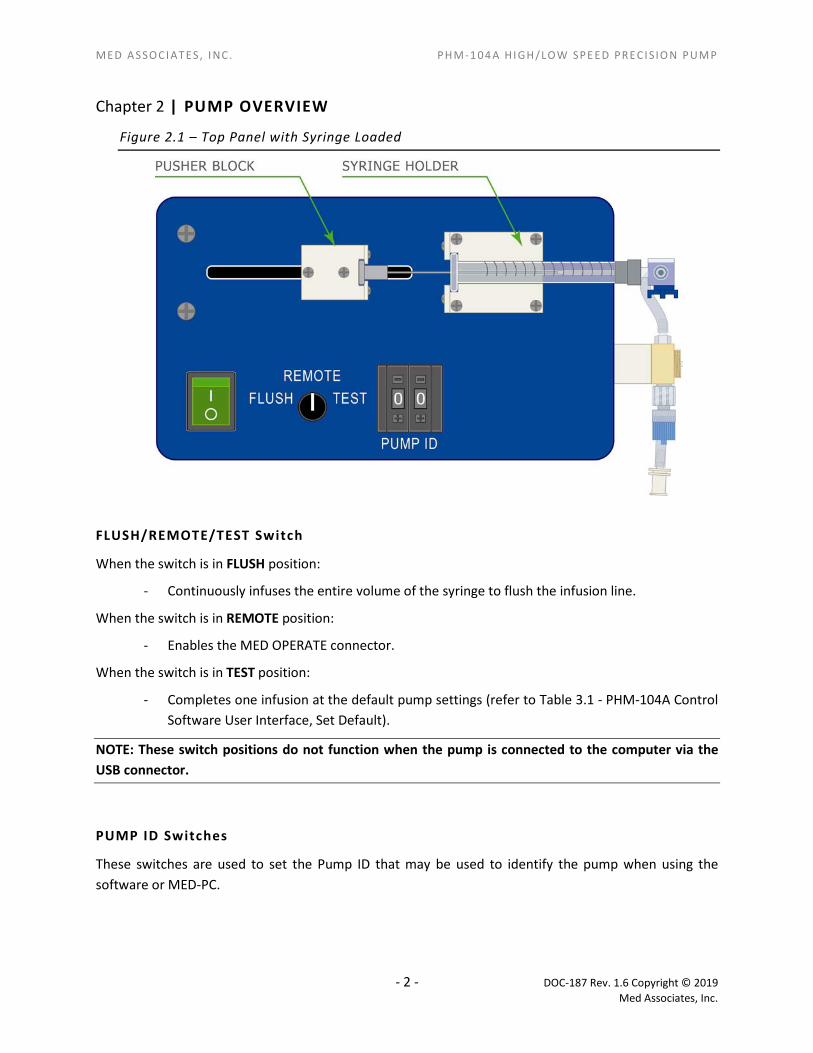
Figure 2.1 – Top Panel with Syringe Loaded
FLUSH/REMOTE/TEST Switch
When the switch is in FLUSH position:
- Continuously infuses the entire volume of the syringe to flush the infusion line.
When the switch is in REMOTE position:
- Enables the MED OPERATE connector.
When the switch is in TEST position:
- Completes one infusion at the default pump settings (refer to Table 3.1 - PHM-104A Control Software User Interface, Set Default).
NOTE: These switch positions do not function when the pump is connected to the computer via the USB connector.
PUMP ID Switches
These switches are used to set the Pump ID that may be used to identify the pump when using the software or MED-PC.
- 2 - DOC-187 Rev. 1.6 Copyright © 2019 Med Associates, Inc.

MED A S SOCI ATES, I NC. PHM-1 04 A HI GH/L OW SPE ED PRE CI S IO N PUM P
Figure 2.2 – Manifold End of the PHM-104A
Figure 2.3 - Control End of the PHM-104A
Figure 2.4 - Syringe Components
- 3 - DOC-187 Rev. 1.6 Copyright © 2019 Med Associates, Inc.

MED A S SOCI ATES, I NC. PHM-1 04 A HI GH/L OW SPE ED PRE CI S IO N PUM P
Dose Capabil it ies
Figure 2.5 - Figure 2.7 display the PHM-104A infusion capabilities for 10 uL, 100 uL and 500 uL syringes, respectively. Infusion rates are dependent upon the size of the syringe and the dose volume. The minimum infusion rate for all three syringe sizes equals 10% of the syringe volume. Any infusion rate included in the highlighted portion of each graph is attainable. Using Figure 5 (10 uL syringe) as an example, a dose of 3 uL may be infused at a rate up to 27 uL/sec. Dose capabilities are based on saline infusion. Pump performance may vary depending upon the viscosity of fluid used. Attempting to pump extremely viscous fluids, especially at high rates, may lead to inaccurate infusion volumes and pump faults.
Figure 2.5 – PHM-104A Pump Dose Capabilities 10 uL
PHM-104A Infusion Capabilities by Dose (10 uL Syringe)
- 4 - DOC-187 Rev. 1.6 Copyright © 2019 Med Associates, Inc.

MED A S SOCI ATES, I NC. PHM-1 04 A HI GH/L OW SPE ED PRE CI S IO N PUM P
Figure 2.6 – PHM-104A Pump Dose Capabilities 100 uL
PHM-104A Infusion Capabilities by Dose (100 uL Syringe)
Figure 2.7 – PHM-104A Pump Dose Capabilities 500 uL
PHM-104A Infusion Capabilities by Dose (500 uL Syringe)
- 5 - DOC-187 Rev. 1.6 Copyright © 2019 Med Associates, Inc.

MED A S SOCI ATES, I NC. PHM-1 04 A HI GH/L OW SPE ED PRE CI S IO N PUM P
| OPERATING INSTRUCTIONS Chapter 3
Syringe Placement
1. Select the desired Hamilton 1700 Series™ syringe size, 10 µl, 100 µl, or 500 µl.
2. Connect the luer end of the syringe to the three-way stopcock on the pump, as indicated in Figure 3.1- Properly Loaded Syringe.
3. Align the syringe plunger with the retainer in the pusher block and align the syringe barrel with the syringe holder, being sure that the syringe tabs are aligned with the retainer.
4. Press down firmly, the syringe should fit snugly.
Figure 3.1- Properly Loaded Syringe
5. When removing a loaded syringe, be sure to grasp the syringe firmly as indicated in Figure 3.2 and lift straight up. Improper removal of the syringe may result in damage to the syringe and/or pump apparatus.
Figure 3.2 - Correct Removal of a Loaded Syringe
- 6 - DOC-187 Rev. 1.6 Copyright © 2019 Med Associates, Inc.

MED A S SOCI ATES, I NC. PHM-1 04 A HI GH/L OW SPE ED PRE CI S IO N PUM P
Hardware Setup
1. Place the infusion solution in a reservoir.
2. Connect a section of tubing of the required length to the Input port on the manifold, shown in Figure 2.2 – Manifold End of the PHM-104A, using a female luer connector.
3. Submerge the other end of the section of tubing in the infusion solution.
4. Connect a section of tubing of the required length to the Output port on the manifold, shown in Figure 2.2 – Manifold End of the PHM-104A, using a female luer connector.
5. Be sure that any air bubbles are evacuated from the system prior to running the pump. Air in the syringe or tubing may cause inaccurate infusions.
6. Connect the other end of this section of tubing to the swivel.
Figure 3.3 - Hardware Setup Diagram
- 7 - DOC-187 Rev. 1.6 Copyright © 2019 Med Associates, Inc.

MED A S SOCI ATES, I NC. PHM-1 04 A HI GH/L OW SPE ED PRE CI S IO N PUM P
Software Control led Operation
NOTE: The PHM-104A drivers and software must be installed prior to using the PHM-104A Control Application. Refer to | PHM-104A Driver and Software Installation for driver and software installation instructions.
1. Using the 24 VDC (2.5 amp) power supply, connect the 24 VOLTS connector on the PHM-104A to a standard wall outlet.
2. Using the included USB cable, connect the USB port on the PHM-104A to the USB port on the computer that was used for driver installation. Connecting the PHM-104A pump to a new USB port will require the reinstalling of the device driver.
3. Set the FLUSH/REMOTE/TEST switch to REMOTE.
4. Set the desired pump I.D. using the PUMP ID pushbuttons switches, shown in.
5. Turn the PHM-104A on using the green ON/OFF switch.
6. Open the PHM-104A Control Application by double-clicking on the desktop shortcut. The screen shown in Figure 3.4 will appear. If there are no pumps properly connected or turned on the message shown in Figure 3.5 will appear. Table 3.1 - PHM-104A Control Software User Interface contains explanations for each of the items on the screen shown in Figure 3.4.
Figure 3.4 - PHM-104A Control Software Screen
Figure 3.5 - Error Message
- 8 - DOC-187 Rev. 1.6 Copyright © 2019 Med Associates, Inc.

MED A S SOCI ATES, I NC. PHM-1 04 A HI GH/L OW SPE ED PRE CI S IO N PUM P
Table 3.1 - PHM-104A Control Software User Interface
Pump ID Pulldown menu that contains PUMP IDs for each pump that was connected to the computer before the application was opened. Select the desired pump to view/change infusion settings.
Reset
Sets the Syringe, Dose, and Rate values to the pump’s default values and causes the PHM-104A Control Application to recognize any pumps that have been connected to the computer after the application was opened. Selecting Reset disables the Download and Set Default buttons. Changing any of the values in the Syringe, Dose, and Rate fields will enable these buttons.
Home Returns the pusher block to the home position. This position varies based on the Syringe, Dose, and Rate settings.
Prime Starts an injection from the current position of the pusher block to the end of the syringe then returns the pusher block to the Home position.
Syringe (µL) Select the size of the Hamilton MICROLITER™ syringe that is loaded in the PHM-104A. Possible selections are 10, 100 and 500 µL.
Dose (µL) Enter the desired dose (µL) in this field.
Rate (µL/sec) Enter the desired rates (µL/sec) in this field. See Figure 2.6 dose capabilities.
OK Indicates that the Dose and Rate settings are within acceptable limits.
Invalid Data Indicates that the value entered in the Dose and Rate fields are not within acceptable limits. Refer to Dose Capabilities for these limits. The value will be reverted back to the last good value used.
Download Click to send Syringe, Dose, and Rate settings to the currently selected pump. If all settings are valid, the Inject and Set Default buttons will be enabled.
Inject Click to inject the dose.
Set Default Enter the desired default values for the pump in the Syringe, Dose and Rate fields and click Download to enable the Set Default button. Click Set Default to save these values as this pump’s defaults. The default values are used when Inject button or the MED-PC input is used after the USB is connected.
7. Select the pump to configure from the Pump ID list. If a pump that is connected to the computer does not appear on this list, verify that it is properly connected and turned on and click the Reset button.
8. This pump’s default values for Syringe, Dose and Rate will be displayed. Click Inject to begin an infusion using the default values or change any of these values to enable the Download and Set Default buttons.
9. If the Syringe, Dose or Rate values are changed, click Download to send the new settings to the pump. If these values are within acceptable limits, the Inject and Set Default buttons will be enabled. If one or more of these values is not within acceptable limits the Status of the pump will indicated as Invalid Data and the Inject and Set Default buttons will not be enabled.
10. Click Inject to begin the infusion or Set Default to save these values as the default settings for this pump.
NOTE: The Inject and Set Default buttons will be disabled until valid values are entered in the Dose and Rate fields and Download is clicked.
- 9 - DOC-187 Rev. 1.6 Copyright © 2019 Med Associates, Inc.

MED A S SOCI ATES, I NC. PHM-1 04 A HI GH/L OW SPE ED PRE CI S IO N PUM P
MED-PC Control led Operation
The pump can be controlled via MED-PC in two different ways. The first uses MED-PC software to set the infusion parameters and controls the pump via the USB connector. The second uses the pump’s default parameters and uses a 28-Volt output to turn the pump on. These methods are both described in detail below.
USB Control Via MED-PC
This section describes controlling the pump using MED-PC. The infusion parameters are set within the MED-PC Program, as described below.
NOTE: The PHM-104A drivers and software must be installed prior to controlling the PHM-104A via MED-PC. Refer to | PHM-104A Driver and Software Installation for driver and software installation instructions.
1. Using the included USB cable, connect the USB port (Figure 2.3) on the pump to the USB port on the computer that was used during the PHM-104A driver installation.
2. Set the desired pump I.D. using the PUMP ID pushbuttons switches, shown in Figure 2.1 – Top Panel with Syringe Loaded. (The pump ID corresponds to the Box in MED-PC).
3. Set the FLUSH/REMOTE/TEST switch to REMOTE.
4. Using the 24 VDC power supply, connect the 24 VOLTS connector on the PHM-104A to a standard wall outlet.
5. Turn the PHM-104A on using the green ON/OFF switch.
6. The sample MED-PC program included in this manual may be used as is, or customized by the user. Please refer to the MED-PC Programmer’s Manual for detailed information regarding the customization of the program.
7. Open Trans IV icon and select Translation | Translate and Compile. Select the program(s) to use and click Make. Click OK to start the translator, and it will automatically parse the MedState Notation and then open to a DOS screen to compile the Pascal code. Depending on the speed of the computer, each of these steps may not be seen. If any problems are encountered during this process, refer to the on-screen help menu or the MED-PC User’s Manual, or contact MED Associates, Inc. for assistance
8. Open MED-PC and run the PHM-104A MED-PC application. Refer to the MED-PC User’s Manual for detailed instructions.
- 10 - DOC-187 Rev. 1.6 Copyright © 2019 Med Associates, Inc.
MED A S SOCI ATES, I NC. PHM-1 04 A HI GH/L OW SPE ED PRE CI S IO N PUM P
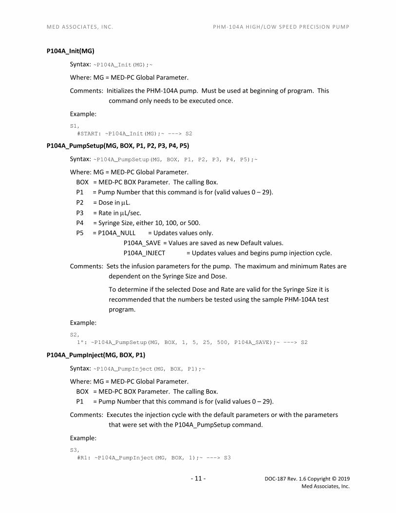
P104A_Init(MG)
Syntax: ~P104A_Init(MG);~
Where: MG = MED-PC Global Parameter.
Comments: Initializes the PHM-104A pump. Must be used at beginning of program. This command only needs to be executed once.
Example:
S1, #START: ~P104A_Init(MG);~ ---> S2
P104A_PumpSetup(MG, BOX, P1, P2, P3, P4, P5)
Syntax: ~P104A_PumpSetup(MG, BOX, P1, P2, P3, P4, P5);~
Where: MG = MED-PC Global Parameter. BOX = MED-PC BOX Parameter. The calling Box. P1 = Pump Number that this command is for (valid values 0 – 29). P2 = Dose in µL. P3 = Rate in µL/sec. P4 = Syringe Size, either 10, 100, or 500. P5 = P104A_NULL = Updates values only.
P104A_SAVE = Values are saved as new Default values. P104A_INJECT = Updates values and begins pump injection cycle.
Comments: Sets the infusion parameters for the pump. The maximum and minimum Rates are dependent on the Syringe Size and Dose.
To determine if the selected Dose and Rate are valid for the Syringe Size it is recommended that the numbers be tested using the sample PHM-104A test program.
Example:
S2, 1": ~P104A_PumpSetup(MG, BOX, 1, 5, 25, 500, P104A_SAVE);~ ---> S2
P104A_PumpInject(MG, BOX, P1)
Syntax: ~P104A_PumpInject(MG, BOX, P1);~
Where: MG = MED-PC Global Parameter. BOX = MED-PC BOX Parameter. The calling Box. P1 = Pump Number that this command is for (valid values 0 – 29).
Comments: Executes the injection cycle with the default parameters or with the parameters that were set with the P104A_PumpSetup command.
Example:
S3, #R1: ~P104A_PumpInject(MG, BOX, 1);~ ---> S3
- 11 - DOC-187 Rev. 1.6 Copyright © 2019 Med Associates, Inc.

MED A S SOCI ATES, I NC. PHM-1 04 A HI GH/L OW SPE ED PRE CI S IO N PUM P
Sample MED-PC Program
\ Copyright (C) 2016 MED Associates, All rights reserved.
\ PHM-104A Pump.mpc High/Low Speed Precision Syringe Pump Program for MED-PC
\ This program demonstrates how to properly call the MED-PC commands that Start
\ and Stop the PHM-104A Pump.
\ When the program is loaded it initializes the pump by calling the P104A_Init
\ command. The program then waits for a response on the Left Lever (Input 1).
\ When a response on the Left Lever is detected the program updates the pump to
\ the currently selected values and then tells the pump to do an infusion.
\ The program then waits 10s for the infusion to complete before looking for
\ another response on the Left Lever.
\ The User may update the Dose, Rate, and Syringe Size at anytime. The new
\ values will be sent to the pump just before the next infusion is to be
\ started.
\ The program records no data and has no end criteria.
\
\ P104A_Init - Initializes the PHM-104A pump. Must be used at the
\ beginning of the program. This command only needs to be
\ executed once.
\
\ P104A_PumpSetup - Sets the infusion parameters for the pump. The maximum and
\ minimum Rates are dependent on the Syringe Size and Dose.
\
\ To determine if the selected Dose and Rate are valid for
\ the Syringe Size it is recommended that the numbers be
\ tested using the sample PHM104A.exe test program.
\
\ P104A_PumpInject - Executes the injection cycle with the default parameters or
\ with the parameters that were set with the P104A_PumpSetup
\ command.
\
\ MG - This is the MED-PC Global Pointer. It allows the PHM-104A to pass
\ back information about any errors that might have occured.
\
\ BOX - This parameter specifies which PHM-104A the command is for. When this
\ program is running in Box 1, then the BOX parameter will equal 1 and the
\ PHM-104A that is set to Node 1 will receive the command. When this
\ program is running in Box 2, then the BOX parameter will equal 2 and the
- 12 - DOC-187 Rev. 1.6 Copyright © 2019 Med Associates, Inc.

MED A S SOCI ATES, I NC. PHM-1 04 A HI GH/L OW SPE ED PRE CI S IO N PUM P
\ PHM-104A that is set to Node 2 will receive the command, etc. This
\ allows the same program to be run in multiple Boxes and control the
\ different Chambers.
\ Inputs
^LeftLever = 1
^RightLever = 2
\ Outputs
^LeftLever = 1
^RightLever = 2
^Pellet = 3
^Dipper = 3 \ If both Pellet and Dipper are ordered
\ It will be necessary to change one of these
^LeftLight = 4
^RightLight = 5
^HouseLight = 7
^Pump = 8
\ A() = Control Variables with Assigned Aliases as Defined
Var_Alias Dose (ul) = A(0) \ Default = 10 ul
Var_Alias Rate (ul/sec) = A(1) \ Default = 50 ul/sec
Var_Alias Syringe Size (ul) = A(2) \ Default = 100 ul Syringe
\ List Working Variables Here
\ B = Response from the P104A_Init Command
\ C = Response from the P104A_PumpSetup Commnad
\ D = Response from the P104A_PumpInject Command
DIM A = 2
- 13 - DOC-187 Rev. 1.6 Copyright © 2019 Med Associates, Inc.

MED A S SOCI ATES, I NC. PHM-1 04 A HI GH/L OW SPE ED PRE CI S IO N PUM P
\***************************************************
\ PHM-104A PUMP Schedule
\ S1 - Set Default Values
\ Dose (10 ul)
\ Rate (50 ul/sec)
\ Syringe Size (100 ul Syringe)
\***************************************************
S.S.1,
S1,
0.01": SET A(0) = 10, A(1) = 50, A(2) = 100 ---> S2
S2, \ Update the Display in case the User changes the values
0.01": SHOW 1,Dose,A(0), 2,Rate,A(1), 3,Syringe Size,A(2) ---> S2
\***************************************************
\ PUMP CONTROL
\***************************************************
S.S.2,
S1, \ Initialize the Pump
0.1": ~B := P104A_Init(MG);~;
SHOW 6,Init Resp,B ---> S2
S2, \ Wait for a Response
\ Send the Currently selected values to the Pump
#R^LeftLever: ~C := P104A_PumpSetup(MG, BOX, BOX, A[0], A[1], A[2], P104A_NULL);~;
SHOW 7,Setup Resp,C ---> S3
S3, \ Turn on the Pump
0.01": ~D := P104A_PumpInject(MG, BOX, BOX);~;
SHOW 8,Inject Resp,D ---> S4
S4, \ Make sure the User can't send another command
\ to the Pump while the Pump is running
10": ---> S2
- 14 - DOC-187 Rev. 1.6 Copyright © 2019 Med Associates, Inc.

MED A S SOCI ATES, I NC. PHM-1 04 A HI GH/L OW SPE ED PRE CI S IO N PUM P
28-V Output Via MED-PC
This section describes the procedure for using a MED-PC 28-Volt output to turn the pump on and off. The pump will operate using the default parameters.
1. Using the 24 VDC power supply connect the 24 VOLTS connector on the PHM-104A to a standard wall outlet.
2. Turn the PHM-104A on using the green ON/OFF switch.
3. Set the pump’s default parameters using the pump control application described in Figure 3.4 - PHM-104A Control Software Screen.
4. Connect the MED OPERATE port (Figure 2.3) on the pump to any available output on a standard MED Connection Panel (e.g. SG-716D), using the included cable.
NOTE: Be sure that the USB cable is NOT connected to the pump, as the MED OPERATE port will not be recognized if it is.
5. Set the FLUSH/REMOTE/TEST switch to REMOTE. The pump will now execute a complete infusion using the default parameters each time it receives a 28-Volt output pulse from MED-PC.
- 15 - DOC-187 Rev. 1.6 Copyright © 2019 Med Associates, Inc.
MED A S SOCI ATES, I NC. PHM-1 04 A HI GH/L OW SPE ED PRE CI S IO N PUM P
| PHM-104A DRIVER AND SOFTWARE INSTALLATION Chapter 4PHM-104A driver and software installation must be completed before the pump can be controlled via software.
NOTE: The PHM-104A driver is specific to the computer USB port that the pump is connected to during driver installation. For this reason, it will be necessary to complete driver installation again if the PHM-104A is connected to a different USB port at a later time.
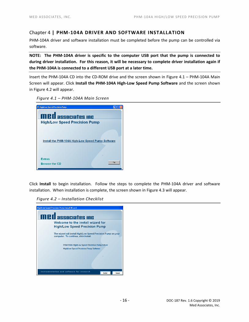
Insert the PHM-104A CD into the CD-ROM drive and the screen shown in Figure 4.1 – PHM-104A Main Screen will appear. Click Install the PHM-104A High-Low Speed Pump Software and the screen shown in Figure 4.2 will appear.
Figure 4.1 – PHM-104A Main Screen
Click Install to begin installation. Follow the steps to complete the PHM-104A driver and software installation. When installation is complete, the screen shown in Figure 4.3 will appear.
Figure 4.2 – Installation Checklist
- 16 - DOC-187 Rev. 1.6 Copyright © 2019 Med Associates, Inc.

MED A S SOCI ATES, I NC. PHM-1 04 A HI GH/L OW SPE ED PRE CI S IO N PUM P
The USB device driver and software installation is now complete. Click Finish to close this screen.
Figure 4.3 – Installation Complete
Using the 24 VDC power supply, connect the 24 VOLTS connector on the PHM-104A to a standard wall outlet.
Using the included USB cable, connect the USB port on the PHM-104A to any available USB port on the computer. The Found New Hardware Wizard screen will appear. Select Install the software automatically (Recommended) and click Next. The PHM-104A driver installation is now complete. Click Finish to close this window.
Figure 4.4 - Found New Hardware Wizard
- 17 - DOC-187 Rev. 1.6 Copyright © 2019 Med Associates, Inc.
MED A S SOCI ATES, I NC. PHM-1 04 A HI GH/L OW SPE ED PRE CI S IO N PUM P
APPENDIX A | CONTACT INFORMATION Please contact Med Associates, Inc. for information regarding any of our products.
For Technical questions, email [email protected].
For Sales questions, email [email protected].
Visit our website at www.med-associates.com.
- 18 - DOC-187 Rev. 1.6 Copyright © 2019 Med Associates, Inc.