
PRECISION PUMP APPLICATOR -...
16
Installation & Operating Instructions User’s Manual For questions and/or product support contact the ITW ROCOL North America Customer Service Department at 800-452-5823 ext. 2. PRECISION PUMP APPLICATOR For Box, Junior, and Custom Applicators
Transcript of PRECISION PUMP APPLICATOR -...
Installation & Operating Instructions
User’s Manual
For questions and/or product support contact the ITW ROCOL North America Customer Service Department at 800-452-5823 ext. 2.
PRECISION PUMP APPLICATOR
For Box, Junior, and Custom Applicators
IntroducIng Accu-Lube
History of ExcellenceSince 1979 Accu-Lube has been the industry leader in manufacturing lubricants and equipment for Minimum Quantity Lubrication (MQL). Today Accu-Lube continues to be at the forefront of MQL and near-dry machining through a dedication to in-novation, safety, and service.
Quality over QuantityAccu-Lube MQL precision pump applicators use advanced technology to focus droplets of lubricant directly onto the tool’s cutting edge, providing lubrication and protection precisely where it is needed. This minimum quantity approach allows manufacturers to conserve fluid and cut down on waste. By eliminating unneeded flood coolant shops remain clean and fluid maintenance is no longer necessary. This process is called Near-Dry Machining.
ITW ROCOL North AmericaITW ROCOL North America, manufacturer of Accu-Lube products, is an industry leader in the development and production of scientifically advanced fluid products for the metalworking industry.
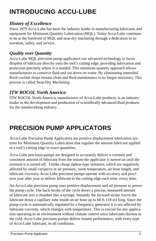
PrecIsIon PumP APPLIcAtorsAccu-Lube Precision Pump Applicators are positive displacement lubrication sys-tems for Minimum Quantity Lubrication that regulate the amount lubricant applied to a tool’s cutting edge in exact quantities.
Accu-Lube precision pumps are designed to accurately deliver a constant and consistent amount of lubricant from the instant the applicator is turned on until the moment it is turned off. Unlike cheap siphon-type imitators, which are negatively affected by small variances in air pressure, room temperature, air hose length, and lubricant viscosity, Accu-Lube precision pumps operate with accuracy and preci-sion year after year to deliver lubricant to the cutting edge each time, every time.
An Accu-Lube precision pump uses positive displacement and air pressure to power the pump cycle. The back stroke of the cycle draws a precise, measured amount of lubricant into a chamber like a syringe. Instantly the forward stroke forces the lubricant down a capillary tube inside an air hose up to 60 ft. (18 m) long. Since the pump cycle is automatically regulated by a frequency generator it is not affected by lubricant viscosity, which changes with temperature. This is crucial for any applica-tion operating in an environment without climate control since lubricants thicken in the cold. Accu-Lube precision pumps deliver instant performance, with every type of Accu-Lube lubricant, in all conditions.
Precision Pump Applicator 2
tAbLe of contents
Components .............................................................4
Preparing ..................................................................5
Installing ..................................................................6
Nozzle Positioning ............................................... 6-7
Operating ..................................................................7
Setting the Lubricant Control ............................... 8-9
Setting the Frequency Generator ...........................10
Re-Priming the Pump .............................................10
Replacing the Hose Assembly ...............................11
Replacement Parts ............................................ 12-13
Warranty .................................................................13
Troubleshooting .....................................................14
Technical Support ..................................................14
unPAckIng & InsPectIngBefore beginning set-up make sure that you have the following items:
Accu-Lube precision pump applicator (Box, Junior, or Custom Applicator)1. Liquid reservoir2. Nozzles and mounting clamps (if applicable)3. 8 oz. LB-2000 sample4. Warranty card, fill out and return within 10 days of purchase5.
If one of these items is missing do not continue with set-up. Contact Customer Service at 800-452-5823 ext. 2 regarding missing/damaged items.
3 Precision Pump Applicator
comPonents
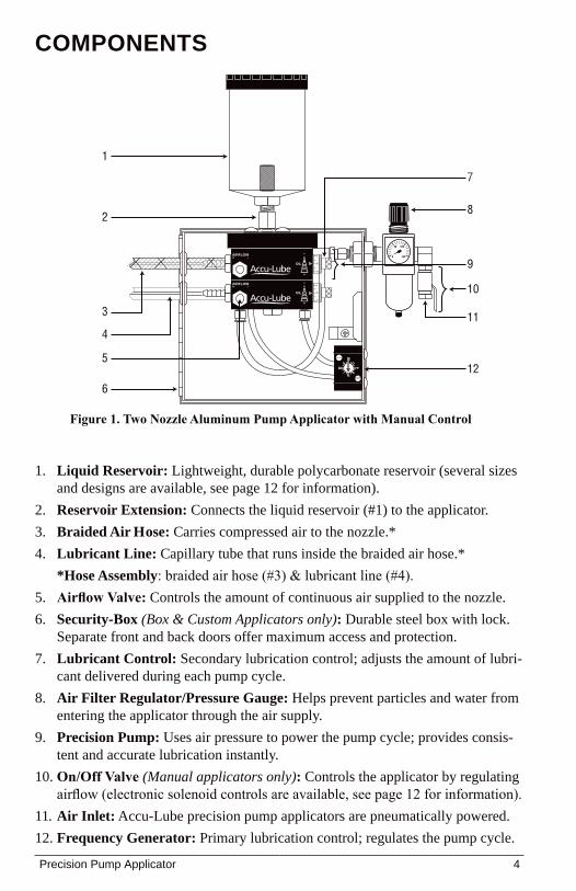
Liquid Reservoir: 1. Lightweight, durable polycarbonate reservoir (several sizes and designs are available, see page 12 for information).Reservoir Extension:2. Connects the liquid reservoir (#1) to the applicator.Braided Air Hose: 3. Carries compressed air to the nozzle.*Lubricant Line:4. Capillary tube that runs inside the braided air hose.**Hose Assembly: braided air hose (#3) & lubricant line (#4).Airflow Valve: 5. Controls the amount of continuous air supplied to the nozzle.Security-Box 6. (Box & Custom Applicators only): Durable steel box with lock. Separate front and back doors offer maximum access and protection. Lubricant Control: 7. Secondary lubrication control; adjusts the amount of lubri-cant delivered during each pump cycle.Air Filter Regulator/Pressure Gauge: 8. Helps prevent particles and water from entering the applicator through the air supply. Precision Pump: 9. Uses air pressure to power the pump cycle; provides consis-tent and accurate lubrication instantly.On/Off Valve 10. (Manual applicators only): Controls the applicator by regulating airflow (electronic solenoid controls are available, see page 12 for information).Air Inlet:11. Accu-Lube precision pump applicators are pneumatically powered.Frequency Generator: 12. Primary lubrication control; regulates the pump cycle.
AIRFLOW+ –
OIL
+
–
OIL
+
–AIRFLOW+ –
III I
I I
I I I I I I I I I I III
0 150
10050
1
6
125
11
10
8
7
2
3
4
9
Figure 1. Two Nozzle Aluminum Pump Applicator with Manual Control
Precision Pump Applicator 4
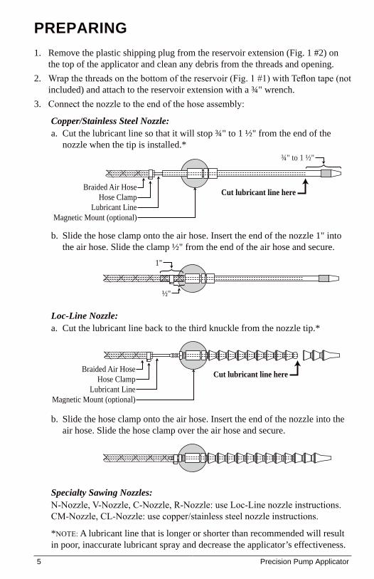
PrePArIngRemove the plastic shipping plug from the reservoir extension (Fig. 1 #2) on 1. the top of the applicator and clean any debris from the threads and opening.Wrap the threads on the bottom of the reservoir (Fig. 1 #1) with Teflon tape (not 2. included) and attach to the reservoir extension with a ¾" wrench.Connect the nozzle to the end of the hose assembly:3.
Copper/Stainless Steel Nozzle:Cut the lubricant line so that it will stop ¾" to 1 ½" from the end of the a. nozzle when the tip is installed.*
Slide the hose clamp onto the air hose. Insert the end of the nozzle 1" into b. the air hose. Slide the clamp ½" from the end of the air hose and secure.
Loc-Line Nozzle:Cut the lubricant line back to the third knuckle from the nozzle tip.*a.
Slide the hose clamp onto the air hose. Insert the end of the nozzle into the b. air hose. Slide the hose clamp over the air hose and secure.
Specialty Sawing Nozzles:N-Nozzle, V-Nozzle, C-Nozzle, R-Nozzle: use Loc-Line nozzle instructions. CM-Nozzle, CL-Nozzle: use copper/stainless steel nozzle instructions.
*NOTE: A lubricant line that is longer or shorter than recommended will result in poor, inaccurate lubricant spray and decrease the applicator’s effectiveness.
1"
½"
Cut lubricant line here
Lubricant LineMagnetic Mount (optional)
Braided Air HoseHose Clamp
¾" to 1 ½"
Cut lubricant line here
Lubricant LineMagnetic Mount (optional)
Braided Air HoseHose Clamp
5 Precision Pump Applicator
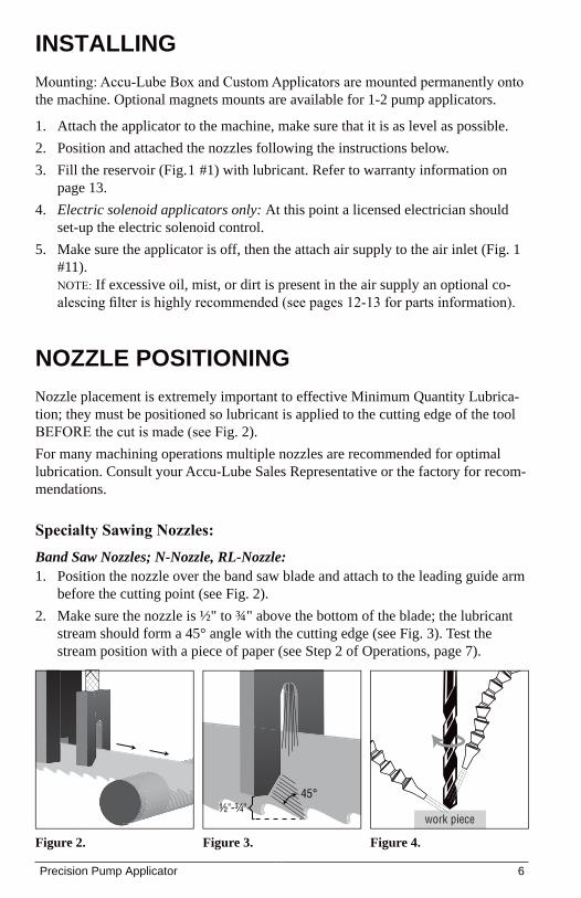
InstALLIng Mounting: Accu-Lube Box and Custom Applicators are mounted permanently onto the machine. Optional magnets mounts are available for 1-2 pump applicators.
Attach the applicator to the machine, make sure that it is as level as possible. 1. Position and attached the nozzles following the instructions below.2. Fill the reservoir (Fig.1 #1) with lubricant. Refer to warranty information on 3. page 13.Electric solenoid applicators only: 4. At this point a licensed electrician should set-up the electric solenoid control.Make sure the applicator is off, then the attach air supply to the air inlet (Fig. 1 5. #11). NOTE: If excessive oil, mist, or dirt is present in the air supply an optional co-alescing filter is highly recommended (see pages 12-13 for parts information).
nozzLe PosItIonIngNozzle placement is extremely important to effective Minimum Quantity Lubrica-tion; they must be positioned so lubricant is applied to the cutting edge of the tool BEFORE the cut is made (see Fig. 2). For many machining operations multiple nozzles are recommended for optimal lubrication. Consult your Accu-Lube Sales Representative or the factory for recom-mendations.
Specialty Sawing Nozzles:Band Saw Nozzles; N-Nozzle, RL-Nozzle:
Position the nozzle over the band saw blade and attach to the leading guide arm 1. before the cutting point (see Fig. 2).Make sure the nozzle is ½" to ¾" above the bottom of the blade; the lubricant 2. stream should form a 45° angle with the cutting edge (see Fig. 3). Test the stream position with a piece of paper (see Step 2 of Operations, page 7).
Figure 2.
45°½"-¾"
Figure 3.
work piece
Figure 4.
Precision Pump Applicator 6
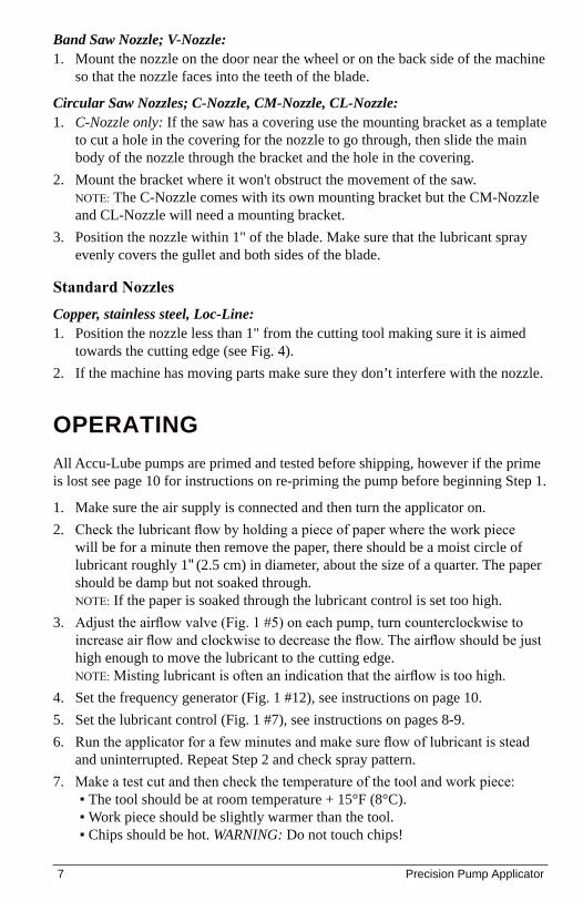
Band Saw Nozzle; V-Nozzle:Mount the nozzle on the door near the wheel or on the back side of the machine 1. so that the nozzle faces into the teeth of the blade.
Circular Saw Nozzles; C-Nozzle, CM-Nozzle, CL-Nozzle:C-Nozzle only: 1. If the saw has a covering use the mounting bracket as a template to cut a hole in the covering for the nozzle to go through, then slide the main body of the nozzle through the bracket and the hole in the covering. Mount the bracket where it won't obstruct the movement of the saw. 2. NOTE: The C-Nozzle comes with its own mounting bracket but the CM-Nozzle and CL-Nozzle will need a mounting bracket.Position the nozzle within 1" of the blade. Make sure that the lubricant spray 3. evenly covers the gullet and both sides of the blade.
Standard Nozzles Copper, stainless steel, Loc-Line:
Position the nozzle less than 1" from the cutting tool making sure it is aimed 1. towards the cutting edge (see Fig. 4).If the machine has moving parts make sure they don’t interfere with the nozzle.2.
oPerAtIng All Accu-Lube pumps are primed and tested before shipping, however if the prime is lost see page 10 for instructions on re-priming the pump before beginning Step 1.
Make sure the air supply is connected and then turn the applicator on.1. Check the lubricant flow by holding a piece of paper where the work piece 2. will be for a minute then remove the paper, there should be a moist circle of lubricant roughly 1" (2.5 cm) in diameter, about the size of a quarter. The paper should be damp but not soaked through. NOTE: If the paper is soaked through the lubricant control is set too high.Adjust the airflow valve (Fig. 1 #5) on each pump, turn counterclockwise to 3. increase air flow and clockwise to decrease the flow. The airflow should be just high enough to move the lubricant to the cutting edge. NOTE: Misting lubricant is often an indication that the airflow is too high.Set the frequency generator (Fig. 1 #12), see instructions on page 10.4. Set the lubricant control (Fig. 1 #7), see instructions on pages 8-9.5. Run the applicator for a few minutes and make sure flow of lubricant is stead 6. and uninterrupted. Repeat Step 2 and check spray pattern.Make a test cut and then check the temperature of the tool and work piece:7.
The tool should be at room temperature + 15°F (8°C). ▪Work piece should be slightly warmer than the tool. ▪Chips should be hot. ▪ WARNING: Do not touch chips!
7 Precision Pump Applicator
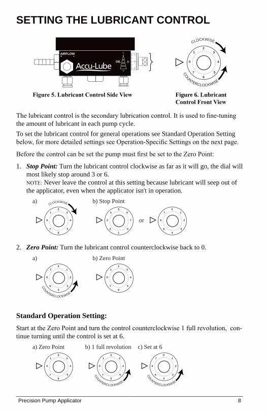
The lubricant control is the secondary lubrication control. It is used to fine-tuning the amount of lubricant in each pump cycle.To set the lubricant control for general operations see Standard Operation Setting below, for more detailed settings see Operation-Specific Settings on the next page.
Before the control can be set the pump must first be set to the Zero Point:
Stop Point:1. Turn the lubricant control clockwise as far as it will go, the dial will most likely stop around 3 or 6. NOTE: Never leave the control at this setting because lubricant will seep out of the applicator, even when the applicator isn't in operation.
Zero Point:2. Turn the lubricant control counterclockwise back to 0.
settIng the LubrIcAnt controL
Standard Operation Setting:Start at the Zero Point and turn the control counterclockwise 1 full revolution, con-tinue turning until the control is set at 6.
a) Zero Point b) 1 full revolution c) Set at 6
0 1
2 3 4 5 6 7
l l l l l l l l l l l l l l l l l l l l
l l l
l l
l l
l l
l l
l l
l
l l l l
l l l l l l l l l l l l l l l l l 0 1
2 3 4 5 6 7
l l l l l l l l l l l l l l l l l l l l
l l l
l l
l l
l l
l l
l l
l
l l l l
l l l l l l l l l l l l l l l l l
CO
UNTERCLOCKWISE
6 7
0 1 2 3 4 5
l l l l l l l l l l l l l l l l l l l l
l l l
l l
l l
l l
l l
l l
l l l
l l l l l l l l l l l l l l l l l l l
CO
UNTERCLOCKWISE
a) b) Stop Point
or0 1
2 3 4 5 6 7
l l l l l l l l l l l l l l l l l l l l
l l l
l l
l l
l l
l l
l l
l l l
l l l l l l l l l l l l l l l l l l l
CLOCKWISE
6 7
0 1 2 3 4 5
l l l l l l l l l l l l l l l l l l l l
l l l
l l
l l
l l
l l
l l
l l l
l l l l l l l l l l l l l l l l l l l 3
4
5 6 7 0 1 2
l l l l l l l l l l l l l l l l l l l l
l l l
l l
l l
l l
l l
l l
l l l
l l l l l l l l l l l l l l l l l l l
a) b) Zero Point
6 7
0 1 2 3 4 5
l l l l l l l l l l l l l l l l l l l l
l l l
l l
l l
l l
l l
l l
l
l l l l
l l l l l l l l l l l l l l l l l 0 1
2 3 4 5 6 7
l l l l l l l l l l l l l l l l l l l l
l l l
l l
l l
l l
l l
l l
l
l l l l
l l l l l l l l l l l l l l l l l
CO
UNTERCLOCKWISE
AIRFLOW+ –
OIL
+
–
Figure 5. Lubricant Control Side View
0 1
2 3 4 5 6 7
l l l l l l l l l l l l l l l l l l l
l l l
l l
l l
l
l l
l l
l l
l l
l l
l l l l l l l l l l l l l l l l l l
CLOCKWISE
CO
UNTERCLOCKWISE
Figure 6. Lubricant Control Front View
Precision Pump Applicator 8
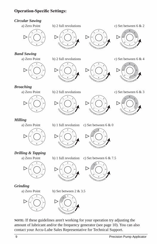
Operation-Specific Settings:
NOTE: If these guidelines aren't working for your operation try adjusting the amount of lubricant and/or the frequency generator (see page 10). You can also contact your Accu-Lube Sales Representative for Technical Support.
a) Zero Point b) 2 full revolutionsBand Sawing
c) Set between 6 & 4
0 1
2 3 4 5 6 7
l l l l l l l l l l l l l l l l l l l l
l l l
l l
l l
l l
l l
l l
l l l
l l l l l l l l l l l l l l l l l l l 0
1
2 3 4 5 6 7
l l l l l l l l l l l l l l l l l l l l
l l l
l l
l l
l l
l l
l l
l l l
l l l l l l l l l l l l l l l l l l l
CO
UNTERCLOCKWISE
6 7
0 1 2 3 4 5
l l l l l l l l l l l l l l l l l l l l
l l l
l l
l l
l l
l l
l l
l l l
l l l l l l l l l l l l l l l l l l l
CO
UNTERCLOCKWISE
0 1
2 3 4 5 6 7
l l l l l l l l l l l l l l l l l l l l
l l l
l l
l l
l l
l l
l l
l l l
l l l l l l l l l l l l l l l l l l l
CO
UNTERCLOCKWISE
a) Zero Point b) 2 full revolutionsBroaching
c) Set between 6 & 3
0 1
2 3 4 5 6 7
l l l l l l l l l l l l l l l l l l l l
l l l
l l
l l
l l
l l
l l
l
l l l l
l l l l l l l l l l l l l l l l l 0 1
2 3 4 5 6 7
l l l l l l l l l l l l l l l l l l l l
l l l
l l
l l
l l
l l
l l
l
l l l l
l l l l l l l l l l l l l l l l l
CO
UNTERCLOCKWISE
6 7
0 1 2 3 4 5
l l l l l l l l l l l l l l l l l l l l
l l l
l l
l l
l l
l l
l l
l l l
l l l l l l l l l l l l l l l l l l l
CO
UNTERCLOCKWISE
0 1
2 3 4 5 6 7
l l l l l l l l l l l l l l l l l l l l
l l l
l l
l l
l l
l l
l l
l
l l l l
l l l l l l l l l l l l l l l l l
CO
UNTERCLOCKWISE
a) Zero Point b) 2 full revolutionsCircular Sawing
c) Set between 6 & 2
0 1
2 3 4 5 6 7
l l l l l l l l l l l l l l l l l l l l
l l l
l l
l l
l l
l l
l l
l l l
l l l l l l l l l l l l l l l l l l l 0
1
2 3 4 5 6 7
l l l l l l l l l l l l l l l l l l l l
l l l
l l
l l
l l
l l
l l
l l l
l l l l l l l l l l l l l l l l l l l
CO
UNTERCLOCKWISE
6 7
0 1 2 3 4 5
l l l l l l l l l l l l l l l l l l l l
l l l
l l
l l
l l
l l
l l
l l l
l l l l l l l l l l l l l l l l l l l
CO
UNTERCLOCKWISE
0 1
2 3 4 5 6 7
l l l l l l l l l l l l l l l l l l l l
l l l
l l
l l
l l
l l
l l
l l l
l l l l l l l l l l l l l l l l l l l
CO
UNTERCLOCKWISE
a) Zero Point b) 1 full revolutionDrilling & Tapping
c) Set between 6 & 7.5
0 1
2 3 4 5 6 7
l l l l l l l l l l l l l l l l l l l l
l l l
l l
l l
l l
l l
l l
l l l
l l l l l l l l l l l l l l l l l l l 0
1
2 3 4 5 6 7
l l l l l l l l l l l l l l l l l l l l
l l l
l l
l l
l l
l l
l l
l l l
l l l l l l l l l l l l l l l l l l l
CO
UNTERCLOCKWISE
6 7
0 1 2 3 4 5
l l l l l l l l l l l l l l l l l l l l
l l l
l l
l l
l l
l l
l l
l l l
l l l l l l l l l l l l l l l l l l l
CO
UNTERCLOCKWISE
a) Zero PointGrinding
b) Set between 2 & 3.5
0 1
2 3 4 5 6 7
l l l l l l l l l l l l l l l l l l l l
l l l
l l
l l
l l
l l
l l
l l l
l l l l l l l l l l l l l l l l l l l 2
3
4 5 6 7 0 1
l l l l l l l l l l l l l l l l l l l l
l l l
l l
l l
l l
l l
l l
l
l l l l
l l l l l l l l l l l l l l l l l
CO
UNTERCLOCKWISE
a) Zero Point b) 1 full revolutionMilling
c) Set between 6 & 0
0 1
2 3 4 5 6 7
l l l l l l l l l l l l l l l l l l l l
l l l
l l
l l
l l
l l
l l
l l l
l l l l l l l l l l l l l l l l l l l 0
1
2 3 4 5 6 7
l l l l l l l l l l l l l l l l l l l l
l l l
l l
l l
l l
l l
l l
l l l
l l l l l l l l l l l l l l l l l l l
CO
UNTERCLOCKWISE
6 7
0 1 2 3 4 5
l l l l l l l l l l l l l l l l l l l l
l l l
l l
l l
l l
l l
l l
l l l
l l l l l l l l l l l l l l l l l l l
CO
UNTERCLOCKWISE
9 Precision Pump Applicator
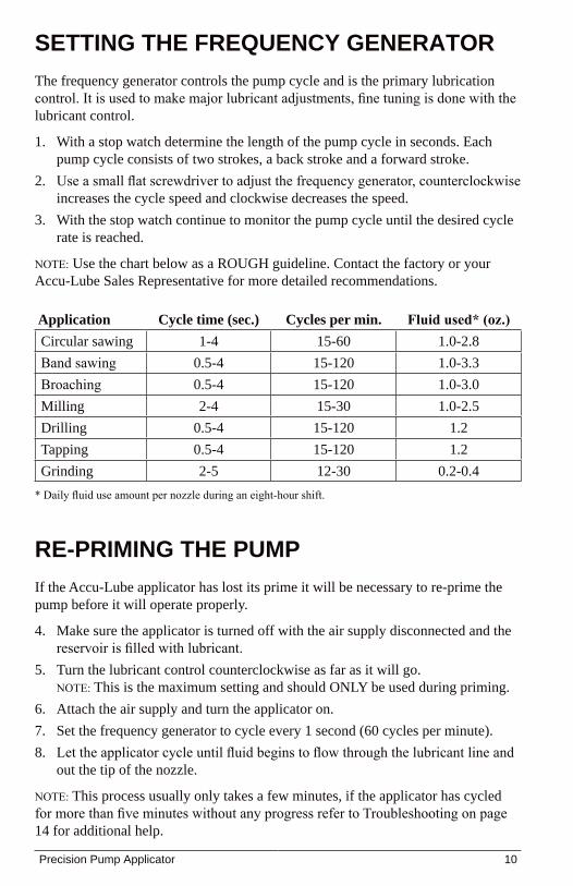
settIng the frequency generAtorThe frequency generator controls the pump cycle and is the primary lubrication control. It is used to make major lubricant adjustments, fine tuning is done with the lubricant control.
With a stop watch determine the length of the pump cycle in seconds. Each 1. pump cycle consists of two strokes, a back stroke and a forward stroke.Use a small flat screwdriver to adjust the frequency generator, counterclockwise 2. increases the cycle speed and clockwise decreases the speed.With the stop watch continue to monitor the pump cycle until the desired cycle 3. rate is reached.
NOTE: Use the chart below as a ROUGH guideline. Contact the factory or your Accu-Lube Sales Representative for more detailed recommendations.
Application Cycle time (sec.) Cycles per min. Fluid used* (oz.)Circular sawing 1-4 15-60 1.0-2.8Band sawing 0.5-4 15-120 1.0-3.3Broaching 0.5-4 15-120 1.0-3.0Milling 2-4 15-30 1.0-2.5Drilling 0.5-4 15-120 1.2Tapping 0.5-4 15-120 1.2Grinding 2-5 12-30 0.2-0.4
* Daily fluid use amount per nozzle during an eight-hour shift.
re-PrImIng the PumPIf the Accu-Lube applicator has lost its prime it will be necessary to re-prime the pump before it will operate properly.
Make sure the applicator is turned off with the air supply disconnected and the 4. reservoir is filled with lubricant.Turn the lubricant control counterclockwise as far as it will go. 5. NOTE: This is the maximum setting and should ONLY be used during priming.Attach the air supply and turn the applicator on.6. Set the frequency generator to cycle every 1 second (60 cycles per minute).7. Let the applicator cycle until fluid begins to flow through the lubricant line and 8. out the tip of the nozzle.
NOTE: This process usually only takes a few minutes, if the applicator has cycled for more than five minutes without any progress refer to Troubleshooting on page 14 for additional help.
Precision Pump Applicator 10
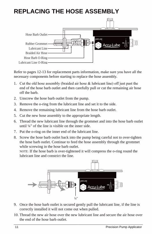
Refer to pages 12-13 for replacement parts information, make sure you have all the necessary components before starting to replace the hose assembly.
Cut the old hose assembly (braided air hose & lubricant line) off just past the 1. end of the hose barb outlet and then carefully pull or cut the remaining air hose off the barb.Unscrew the hose barb outlet from the pump.2. Remove the o-ring from the lubricant line and set it to the side.3. Remove the remaining lubricant line from the hose barb outlet.4. Cut the new hose assembly to the appropriate length.5. Thread the new lubricant line through the grommet and into the hose barb outlet 6. until ¼" of the line is visible on the inner side.Put the o-ring on the inner end of the lubricant line.7. Screw the hose barb outlet back into the pump being careful not to over-tighten 8. the hose barb outlet. Continue to feed the hose assembly through the grommet while screwing in the hose barb outlet. NOTE: If the hose barb is over-tightened it will compress the o-ring round the lubricant line and constrict the line.
rePLAcIng the hose AssembLy
Once the hose barb outlet is secured gently pull the lubricant line, if the line is 9. correctly installed it will not come out when pulled.Thread the new air hose over the new lubricant line and secure the air hose over 10. the end of the hose barb outlet.
OIL
+
–AIRFLOW+ –
Hose Barb O-RingLubricant Line O-Ring
Braided Air Hose
Rubber Grommet
Hose Barb Outlet
Lubricant Line
OIL
+
–AIRFLOW+ –
¼"
11 Precision Pump Applicator
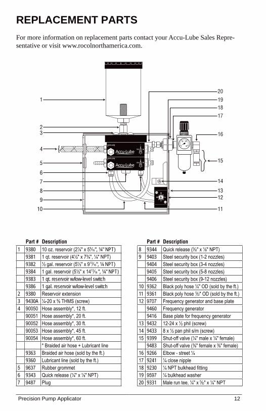
rePLAcement PArtsFor more information on replacement parts contact your Accu-Lube Sales Repre-sentative or visit www.rocolnorthamerica.com.
Part # Description1 9380 10 oz. reservoir (2⅞" x 59⁄16", ¼" NPT)
9381 1 qt. reservoir (4½" x 7¾", ¼" NPT)9382 ½ gal. reservoir (5½" x 913⁄16", ¼ NPT)9384 1 gal. reservoir (5½" x 1413⁄16 ", ¼" NPT)9383 1 qt. reservoir w/low-level switch9386 1 gal. reservoir w/low-level switch
2 9380 Reservoir extension3 9430A ¼-20 x ⅝ THMS (screw)4 90050 Hose assembly*, 12 ft.
90051 Hose assembly*, 20 ft.90052 Hose assembly*, 30 ft.90053 Hose assembly*, 45 ft.90054 Hose assembly*, 60 ft.
* Braided air hose + Lubricant line9363 Braided air hose (sold by the ft.)9360 Lubricant line (sold by the ft.)
5 9637 Rubber grommet6 9343 Quick release (¼" x ⅛" NPT)7 9487 Plug
Part # Description8 9344 Quick release (5⁄32" x ⅛" NPT)9 9403 Steel security box (1-2 nozzles)
9404 Steel security box (3-4 nozzles)9405 Steel security box (5-8 nozzles)9406 Steel security box (9-12 nozzles)
10 9362 Black poly hose ¼" OD (sold by the ft.)11 9361 Black poly hose 5⁄32" OD (sold by the ft.) 12 9707 Frequency generator and base plate
9460 Frequency generator9416 Base plate for frequency generator
13 9432 12-24 x ½ phil (screw)14 9433 8 x ½ pan phil s/m (screw)15 9399 Shut-off valve (¼" male x ¼" female)
9483 Shut-off valve (⅜" female x ⅜" female)16 9266 Elbow - street ¼17 9241 ¼ close nipple18 9230 ¼ NPT bulkhead fitting19 9597 ¼ bulkhead washer20 9331 Male run tee, ¼" x 5⁄32" x ¼" NPT
AIRFLOW+ –
OIL
+
–
OIL
+
–AIRFLOW+ –
III I
I I
I I I I I I I I I I III
0 150
10050
1
12
23
5
4
8 13
14
10
16
17181920
15
6
7
9
11
Precision Pump Applicator 12
Part # Description Pump
Rep
air K
it (#9
668)
Pump
Rep
air K
it w/P
iston
(#90
65)
Hose
Bar
b Rep
air K
it (#3
0904
0)
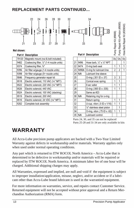
Qty. Qty. Qty.21 9496 Hose barb, ¼" x ⅛" NPT 122 9474 O-ring barb seal 1 1 123 9490A O-ring for lubricant line 2 2 124 N/A Lubricant line sleeve25 O-ring (.301 ID x .07) 3 326 Conical evac spring 1 127 Evac valve 1 128 O-ring (.065 ID x .035) 1 129 Same as #2330 N/A Retaining ring for o-ring31 Return spring 1 132 U-cup, viton (.5 ID x 1/16) 1 133 ⅛" stainless steel piston 134 O-ring, viton (.75 ID x .62) 1 135 N/A Lubricant control
Parts 24, 30, and 35 can not be replacedParts 25-28 and 31-34 are only available in kits
Not shown:
Part # Description79120 Magnetic mount (nut & bolt included)9402 Coalescing filter, ¼" (1-4 nozzle units)9374 Coalescing filter, ⅜"9396 Air filter w/gauge (1-4 nozzle units)9398 Air filter w/gauge (5+ nozzle units)9046 Frequency generator repair kit9518 Electric solenoid, 110 VAC (¼" NPT)9522 Electric solenoid, 220 VAC (¼" NPT)9526 Electric solenoid, 440 VAC 9524 Electric solenoid, 100 VAC (stacking)9519 Electric solenoid, 200 VAC9516 Electric solenoid, 24 VDC (¼" NPT)9202 Complete lock assembly
rePLAcement PArts contInued...
WArrAntyAll Accu-Lube precision pump applicators are backed with a Two-Year Limited Warranty against defects in workmanship and/or materials. Warranty applies only when used under normal operating conditions.
Any part which is returned to ITW ROCOL North America – Accu-Lube that is determined to be defective in workmanship and/or materials will be repaired or replaced by ITW ROCOL North America. A minimum labor fee of one hour will be charged. Additional shipping charges may apply.
All Warranties, expressed and implied, are null and void if the equipment is subject to improper installation/application, misuse, neglect, and/or accident or if a lubri-cant other than Accu-Lube brand lubricant is used in the warrantied equipment.
For more information on warranties, service, and repairs contact Customer Service. Returned equipment will not be accepted without prior approval and a Return Mer-chandise Authorization (RMA) form.
21
22
23
24 26
25
32
31 33
3430
29
28
27 35
13 Precision Pump Applicator
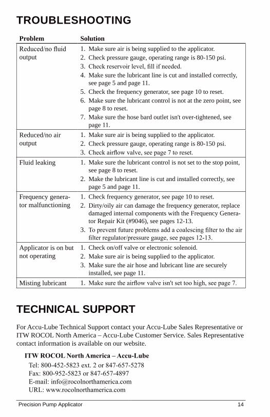
troubLeshootIngProblem SolutionReduced/no fluid output
Make sure air is being supplied to the applicator.1. Check pressure gauge, operating range is 80-150 psi.2. Check reservoir level, fill if needed.3. Make sure the lubricant line is cut and installed correctly, 4. see page 5 and page 11.Check the frequency generator, see page 10 to reset.5. Make sure the lubricant control is not at the zero point, see 6. page 8 to reset.Make sure the hose bard outlet isn't over-tightened, see 7. page 11.
Reduced/no air output
Make sure air is being supplied to the applicator.1. Check pressure gauge, operating range is 80-150 psi.2. Check airflow valve, see page 7 to reset.3.
Fluid leaking Make sure the lubricant control is not set to the stop point, 1. see page 8 to reset. Make the lubricant line is cut and installed correctly, see 2. page 5 and page 11.
Frequency genera-tor malfunctioning
Check frequency generator, see page 10 to reset.1. Dirty/oily air can damage the frequency generator, replace 2. damaged internal components with the Frequency Genera-tor Repair Kit (#9046), see pages 12-13.To prevent future problems add a coalescing filter to the air 3. filter regulator/pressure gauge, see pages 12-13.
Applicator is on but not operating
Check on/off valve or electronic solenoid.1. Make sure air is being supplied to the applicator.2. Make sure the air hose and lubricant line are securely 3. installed, see page 11.
Misting lubricant Make sure the airflow valve isn't set too high, see page 7.1.
technIcAL suPPortFor Accu-Lube Technical Support contact your Accu-Lube Sales Representative or ITW ROCOL North America – Accu-Lube Customer Service. Sales Representative contact information is available on our website.
ITW ROCOL North America – Accu-Lube Tel: 800-452-5823 ext. 2 or 847-657-5278Fax: 800-952-5823 or 847-657-4897E-mail: [email protected]: www.rocolnorthamerica.com
Precision Pump Applicator 14
notes
Model Number:
Serial Number:
Purchase Date:
Distributor:
15 Precision Pump Applicator
Installation & Operating InstructionsUser’s Manual
3624 West Lake Avenue, Glenview, Illinois 60026Phone: 800-452-5823/847-657-5278Fax: 800-952-5823/[email protected] Revised 08/2009
PRECISION PUMP APPLICATOR