PUMP SYSTEM - Cole-Parmer · Installing Tubing in Pump Head ... Depending on the Pump System model,...
12
OPERATING MANUAL: PUMP SYSTEM The MASTERFLEX C/L Pump Systems are small peristaltic pumps with integral drive motors and are intended for use with a series of tubing sizes that provide flow rates in the range of 2.0 μL/min to 50 mL/min. 77122-04 77122-14 77122-24 77122-06 77122-16 77122-26 Model No. A-1299-1073 Edition 01 1-800-MASTERFLEX (627-8373) (U.S. and Canada only) • 11 (847) 549-7600 (Outside U.S.) (847) 549-7600 (Local) • www.masterflex.com • techinfo@coleparmer.com
Transcript of PUMP SYSTEM - Cole-Parmer · Installing Tubing in Pump Head ... Depending on the Pump System model,...

OPERATING MANUAL:
PUMP SYSTEM
The MASTERFLEX C/L Pump Systems are small peristalticpumps with integral drive motors and are intended for use with a series of tubing sizes that provide flow rates in the range of 2.0 µL/min to 50 mL/min.
77122-0477122-1477122-24
77122-0677122-1677122-26
Model No.
A-1299-1073Edition 01
1-800-MASTERFLEX (627-8373) (U.S. and Canada only) • 11 (847) 549-7600 (Outside U.S.)(847) 549-7600 (Local) • www.masterflex.com • [email protected]

SAFETY PRECAUTIONS
WARNING: PRODUCT USE LIMITATIONThese products are not designed for, nor intended for use in patient connected applications; including, but not limited to, medical and dental use, and accordingly have not been submitted for FDA approval.
TABLE OF CONTENTSPageTitle
SAFETY PRECAUTIONS .......................................................2INTRODUCTION .....................................................................3GENERAL DESCRIPTION .....................................................4SETUP ....................................................................................5
Selecting Tubing Size.......................................................5Installing Tubing in Pump Head .......................................5Installing Panel Mount Mounting Brackets .......................6Installing Rubber Feet ......................................................6Connecting Primary Power ..............................................6Backup Battery Connection..............................................6Remote Start/Stop Connection.........................................6
OPERATION ...........................................................................7Turning Pump System On and Selecting Direction ofOperation .........................................................................7Setting Pump Speed ........................................................7Priming Pump System......................................................7
MAINTENANCE ......................................................................7Cleaning ...........................................................................7Replacement Parts and Accessories ...............................7
SPECIFICATIONS...................................................................8WARRANTY............................................................................9PRODUCT RETURN...............................................................9TECHNICAL ASSISTANCE ....................................................9APPENDIX A
Available Microbore Autoanalysis Tubing ......................10Tubing Flow Rates..........................................................11
2
NORYL — Reg TM General Electric CompanyC-FLEX, PHARMED, TYGON — Reg TM Saint-Gobain Performance Plastics Corp.VITON — Reg TM E.I. duPont DeNemours & Co.
Trademarks bearing the ® symbol in this publication are registered in the U.S.and in other countries.
PUMP FOR LIQUIDSORIGINAL INSTRUCTIONS
These products are covered by one or more of the following U.S. and corresponding foreign patents: D605,286S.
DANGER: Remove power from the Pump System before any cleaning operation is started.
WARNINGS: Tubing breakage may result in fluid being sprayed from pump. Use appropriate measures to protect operator and equipment.
CAUTIONS: Tubing for use with the MASTERFLEX C/L Pump Systems is Microbore Autoanalysis Tubing. See Appendix A for specifics. Use of tubing other than that specified will result in poor pumping performance and/or pump system damage and voiding of applicable warranty.
Before installing tubing into the Pump Head remove power or shut off the drive. Fingers or loose clothing could be caught in the rollers.
Do Not pull the tubing too tight. Do not pinch the tubing to cause it to be closed off.
3
INTRODUCTIONThe MASTERFLEX C/L Pump System is designed to pumpfluid through Microbore Autoanalysis tubing by means of peristaltic action at very low flow rates. It is ideal for sanitizers, reagent dispensing, analyzers, printing systems, controlled feeding and non-human infusion procedures.

4
The MASTERFLEX C/L Pump System,Figure 1, is enclosed in a plastic 1/4 DINCase.
Rubber Feet, supplied with the unit, can beattached to the bottom of the Case for oper-ating on a bench or other flat surface and forstability when stacking multiple units. Theenclosure allows panel mounting usingoptional Mounting Brackets (see AccessorySection for Part No. and page 6 for mountinginstructions).
The Pump System accommodates one tubeat controlled speeds as low as 1.7 rpm.Tubing is held in place by spring-loadedTubing Retainers. For a list of tubing sizesfor use with the Pump System, refer toAppendix A.
The self-closing Occlusion Bed allows quickloading or changing of tubing. The PumpHead Rotor contains four rollers for minimum pulsation. All units operate froman External DC Power Supply. The ACmodels are supplied with a Universal PowerSupply, which provides a DC output for connection to the Pump Drive.
The single-turn, adjustable speed control knob, Figure 2, provides variable flow -operation. The green PWR On indicatorlights whenever the pump is operating. ThePower On/Direction Switch turns power onwhen either clockwise or counterclockwisepump rotor direction is selected. The MAXButton is used for priming and purging andoperates the pump at maximum speed whiledepressed.
Figure 2. Pump — Front
GENERAL DESCRIPTION
Figure 1. MASTERFLEX C/L Pump System
Pump Assembly PWR OnIndicator
MAX: Press and hold to prime or purge pump
Speed Control Knob: Provides variable flow adjustment
Power On/Direction Switch
Bezel1/4 DIN Case
MountingBracket
(not Supplied)
UniversalPower Supply

5
SETUPUse only Microbore Autoanalysis tubing with MASTERFLEX C/L pumps to ensure optimum performance. Use of other tubing may void applicable warranties.
Selecting Tubing SizeAppendix A provides a list of tubing sizes which will work efficiently with the MASTERFLEX C/L Pump System. This list includes tubing diameters, flow rates in µL/min and the maximum flow rates at 10 rpm, 80 rpm and 300 rpm. Tubing is listed by part number.
Installing Tubing in Pump Head WARNING:
1. When the door is opened the Occlusion Bed moves back away from the pump rollers, Figure 4.
2. Holding both ends of the tubing in one hand, form a loop andwrap the tubing around the Rollers, Figure 4, making surethat the tubing is centered on the rollers and keeping the freeends of the tubing outside of the Tubing Retainers, Figure 4
.3. Once the tubing is in place, close the Door and the Occlusion Bed will automatically align itself within the pump, Figure 5.
4. Insert the tubing into one of the Tubing Retainers, Figure 4
,by moving the retainer toward the center of the pump andplacing the tubing in the v-notch of the retainer. Release theretainer so that the tubing is secured in place. Repeat for theother tubing retainer. The tubing should be stretched slightlyaround the rollers so that there is no excess tubing betweenthe rollers and the retainers – any excess can be removed bypulling slightly on the tubing outside of the pump.
Figure 3. Pump — Rear Panel
DC Power Input,2.5 mm Coaxial Receptacle
BackupDC
Input
RemoteStart/Stop
Input
Shorting Bar
The rear panel, Figure 3, contains a DC power input jack forconnection of primary power and a 4-terminal barrier strip forconnection of remote start/stop and for a DC backup supply.
Figure 4. Occlusion Bed in Unlatched Tube Loading Position
Figure 5. Closing Occlusion Bed
Shorting Bar
Rollers
Occlusion Bed
Tubing Retainers
Occlusion Bed
Before installing tubing into the Pump Head remove power or shut off the drive. Fingers or loose clothing could be caught in the rollers.

Installing Panel MountMounting Brackets The optional Mounting Brackets are used to attach the 1/4 DINCase to a Mounting Rack. Use Mounting Brackets Part No.77120-03, (2/set).
1. Be sure the panel bezel is on the pump, then slide thepump system through the front of the mounting rack.
2. Place a Mounting Bracket, Figure 6, between the groovedbracket retainers on one side of the Case and slide theMounting Bracket back to lock into the retainer grooves.
3. Tighten the bracket screw against the back of the rack tohold the Pump System in place.
4. Repeat steps 2 and 3 for the second Mounting Bracket on the opposite side.
Installing Rubber Feet Four rubber feet are provided for operating the Pump Systemon a bench or other flat surface and for stability when stackingmultiple units. The feet should be installed at the four cornerson the bottom of the unit. Remove the protective paper from the adhesive surface of each foot and press the foot firmly on the bottom surface about one-eighth inch in from and parallel to the outer edges.
Connecting Primary PowerDepending on the Pump System model, primary power maybe 100-240V AC or 12V DC. The DC models can be con-nected to any DC* supply and are not supplied with aUniversal Power Supply unit. Connect the External PowerSupply to the applicable input voltage source and the output of the External Power Supply to the DC input connector on the pump unit.*Refer to Specifications for current supply voltage.
NOTE: The Power Supply output connection is center positive (+).
6
Backup Battery ConnectionTerminals 1 and 2 on the rear panel Barrier Terminal Strip,Figure 3, provide a means for connecting a backup DC powersource. The positive (+) terminal is terminal 1. The negative(–) terminal is terminal 2. Connection to these terminals wouldusually be made only for emergency type operation in con-junction with an External Power Supply, or a stand-alone oper-ation for the DC models.
NOTE: Input voltage must not exceed 15V DC or equipmentmay be damaged. A minimum of 11.0V DC is required forproper operation.
Remote Start/Stop ConnectionTerminals 3 and 4 on the rear panel Terminal Strip, Figure 3,are used for remote start/stop operation. Pump direction andspeed are not remotely controllable. In non-remote operation,these terminals are connected together by a Shorting Bar.
For remote control by switch closure, remove the Shorting Barand connect the two terminals of the remote control switch toterminals 3 and 4. A closure of the remote control switch con-tacts will start the Pump System. Opening the contact will stop the Pump System.
Figure 6. Mounting Bracket Installation
MountingBracket
BracketRetainers
Bezel

This section describes the procedures for obtaining desiredperformance. Flow rate is determined by the drive speed andthe tubing size.
WARNING: Tubing breakage may result in fluidbeing sprayed from pump. Use appropriate measures to protect operator and equipment.
Turning Pump System On andSelecting Direction of OperationThe Pump System can be set to operate in either a clockwiseor a counterclockwise direction. The same control used toselect direction also turns power on or off. Select direction ofpump operation desired. PWR indicator should light.
Setting Pump SpeedPump speed is controlled by the variable speed control knob.Turning the control clockwise increases the speed. Tube lifeis decreased with increased operating speed.
Priming Pump System The MAX Push Button is used for priming and purging thePump System. When MAX is depressed, the pump operatesat maximum speed in the selected direction until the button isreleased. Approximately two feet of tubing length can be filledor emptied per minute using the MAX Push Button on the 10rpm units.
7
OPERATION
CleaningClean exterior surfaces of case, control panel and pumprollers using dry or damp cloth. Never immerse nor use excessive fluid.
Replacement Parts and Accessories.oN traP metI
1-CR000-0931-A).ae 4( teeF rebbuR2044-AraB gnitrohS
111185-CR Pump Assembly 3 Roller111186-CRPump Assembly 4 Roller
.oN traP yrosseccA30-02177 )tes/2( stekcarB gnitnuoM
Universal Power Supply 100-240V AC
MAINTENANCE DANGER: Remove power from the Pump System
before any cleaning operation is started.
77200-07

8
Output:Operating Speed:Models 77122-04 and 77122-06Models 77122-14 13 to 80 rpmand 77122-16Models 77122-24and 77122-26Maximum No. of Tubes: 1Direction of rotation: Clockwise and
Counterclockwise
Input:Supply Voltage/Frequency:Model 77122-04, -14, -24
(90–130V AC) @ 400 mA AC230V AC nominal, 50/60 Hz(190–260V AC) @ 250 mA max.
Model 77122-06, -16, -26 (11.0–15.0V DC) @ 2.4 A DC
Power Input: 11.0–15.0V DC to terminals1 and 2 of terminal strip or External Power Supply
Installation Category:77122-04, -14, -24
(Local level—appliances,portable equipment, etc.)
77122-06, -16, -26(Signal Level)
Remote Start/Stop: Contact Closure connectionat terminal strip contacts 3and 4
Construction:Dimensions (L x W x H): 7.0 in x 3.5 in x 3.5 in
(17.8 cm x 8.9 cm x 8.9 cm)Weight: 1.5 pounds (0.68 kg)Color: BlackMaterial:Pump Head: PPS, polyester
and stainless steelCase: NORYL®
Enclosure Rating: IP22 per IEC529
Environment:Operating Temperature: 32°F to 105°F (0°C to 40°C)
Noise Level:
Maximum Operating Pressure:
Storage Temperature: –49°F to 149°F (–45°C to 65°C)Humidity (Non-cond): 10% to 90%Altitude: Less than 6600 ft (2000 m)Pollution Degree: Pollution Degree 2 per IEC664
(Indoor usage — lab, office)
Compliance (For CE Mark):EN61326-1/A2: 2001 (EMC Directive)EN809 (EU Machinery Directive)2011/65/EU (RoHS Directive)Converter is UL, cUL listed and CE, CCC approved.Regulatory agency specifications not applicable to the balance of the unit due to low voltage.
SPECIFICATIONS
1.7 to 10 rpm
50 to 300 rpm
115V AC nominal, 50/60 Hz
12.0V DC nominal,
Category II per IEC664
Category I per IEC664
15 PSIG<70dBa @ 1 meter

WARRANTYUse only Microbore Autoanalysis tubing with MASTERFLEX C/L pumps to ensure optimumperformance. Use of other tubing may void applicable warranties.
The Manufacturer warrants this product to be free from
significant deviations from published specifications. If repair or
adjustment is necessary within the warranty period, the prob-
lem will be corrected at no charge if it is not due to
misuse or abuse on your part, as determined by the
Manufacturer. Repair costs outside the warranty period, or
those resulting from product misuse or abuse, may be
invoiced to you.
The warranty period for this product is one (1) year fromdate of purchase.
PRODUCT RETURNTo limit charges and delays, contact the seller or Manufacturer
for authorization and shipping instructions before returning the
product, either within or outside of the warranty period. When
returning the product, please state the reason for the return.
For your protection, pack the product carefully and insure it
against possible damage or loss.
Any damages resulting from improper packaging are your
responsibility.
TECHNICAL
ASSISTANCEIf you have any questions about the use of this product,
contact the Manufacturer or authorized seller.
9

APPENDIX A CAUTION: Tubing for use with the MASTERFLEX C/L Pump Systems is Microbore Autoanalysis Tubing. Use
of tubing other than that specified will result in poor pumping performance and/orpump system damage and voiding of applicable warranty.
Available Microbore Autoanalysis Tubing
10
NOTE: White indicates AvailableBlack indicates Not AvailableDark Gray indicates Special Order – check with factory.
Tubing
Suffix
Tubing
ID in (mm)
PHARMED®BPT
Silicone Peroxide
Silicone Platinum
TYGON®Lab
TYGON®Food XELF-C ® TYGON®
E-LFLSolvent/
Hydrocarbon VITON®
95809 07625 95590 06460 06457 95718 06449 95712 97632
-10 0.007 (0.19)
-12 0.010 (0.25)
-14 0.015 (0.38)
-16 0.017 (0.44)
-18 0.020 (0.51)
-22 0.025 (0.64)
-24 0.030 (0.76)
-26 0.035 (0.89)
-28 0.040 (1.02)
-30 0.045 (1.14)
-32 0.051 (1.30)
-34 0.056 (1.42)
-36 0.060 (1.52)
-38 0.065 (1.65)
-40 0.073 (1.85)
-42 0.081 (2.06)
-44 0.090 (2.29)
-46 0.100 (2.54)
-48 0.110 (2.79)
11
Tubing Tubing Flow Rate
Suffix. ID 10 rpm 80 rpm 300 rpm
in (mm) (µL/min) (µL/min) (µL/min)
-10 0.007 (0.19) 13.0 100 425
-12 0.010 (0.25) 22.5 180 730
-14 0.015 (0.38) 50.5 400 1650
-16 0.017 (0.44) 67.0 535 2200
-18 0.020 (0.51) 87.0 700 2900
-22 0.025 (0.64) 135 1050 4500
-24 0.030 (0.76) 185 1450 6250
-26 0.035 (0.89) 245 1950 8300
-28 0.040 (1.02) 315 2500 10400
-30 0.045 (1.14) 385 3100 13000
-32 0.051 (1.30) 485 3850 16300
-34 0.056 (1.42) 565 4500 19100
-36 0.060 (1.52) 635 5100 21300
-38 0.065 (1.65) 730 5850 24700
-40 0.073 (1.85) 885 7100 29800
-42 0.081 (2.06) 1050 8500 35200
-44 0.090 (2.29) 1250 9350 41000
-46 0.100 (2.54) 1450 10200 46200
-48 0.110 (2.79) 1650 11000 50000
All flow rates based on pumping water @ 0 psig 70°F (21°C).
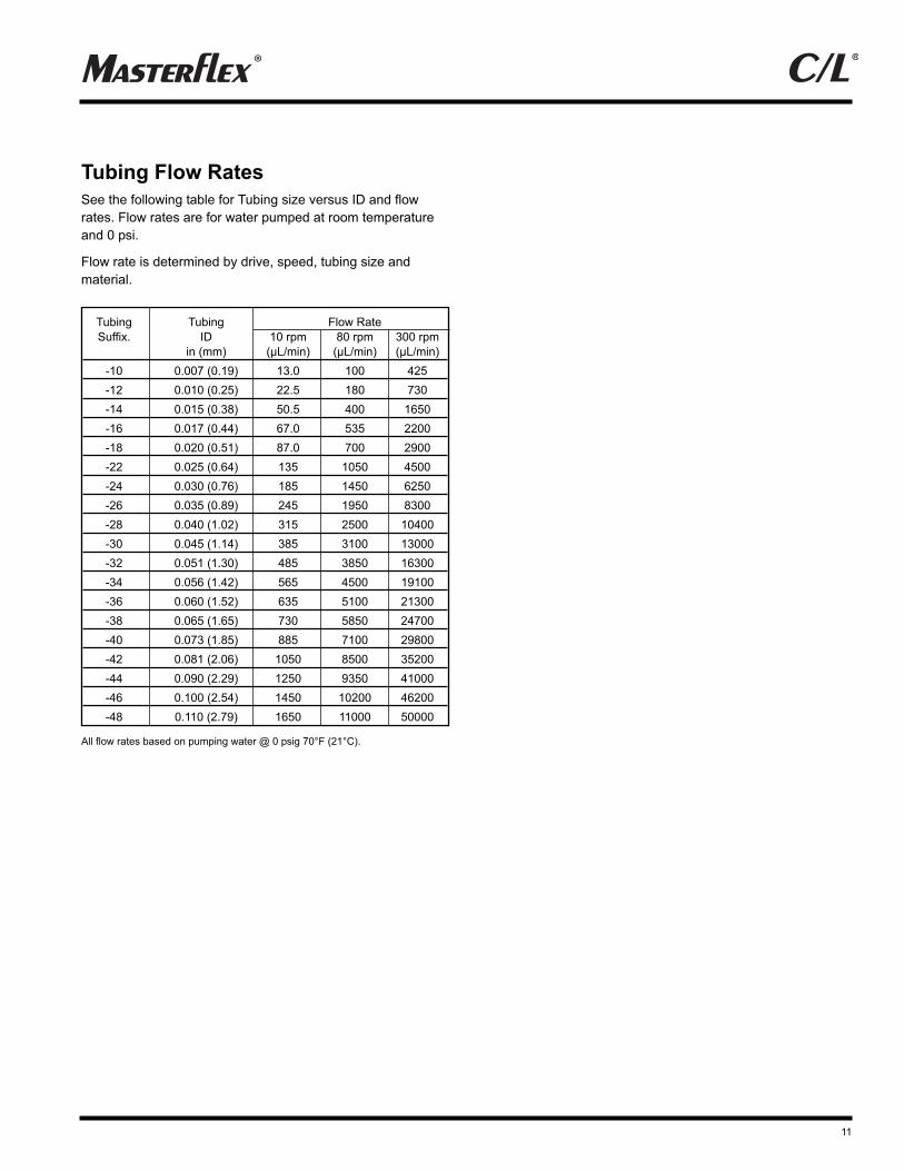
See the following table for Tubing size versus ID and flow
rates. Flow rates are for water pumped at room temperature
and 0 psi.
Flow rate is determined by drive, speed, tubing size and
material.
Tubing Flow Rates

12
Printed in U.S.A.
1-800-MASTERFLEX (627-8373) (U.S. and Canada only)
11 (847) 549-7600 (Outside U.S.)(847) 549-7600 (Local)www.masterflex.com
*EN809 manufactured by:Thermo Fisher Scientific
28W092 Commercial AvenueBarrington, IL 60010 USA
1-800-637-3739 (U.S. and Canada only)11 (847) 381-7050 (Outside U.S.)
(847) 381-7050 (Local)www.thermoscientific.com