High Temperature Low Cycle Fatigue Mechanisms for a Nickel ...
111
NASA Contractor Report 3543 NASA I CR High Temperature Low Cycle Fatigue Mechanisms for a Nickel-Base and a Copper-Base Alloy Chin-I Shih GRANT NSG-3263 JUNE 1982
Transcript of High Temperature Low Cycle Fatigue Mechanisms for a Nickel ...

NASA Contractor Report 3543
NASA I CR
High Temperature Low Cycle Fatigue Mechanisms for a Nickel-Base and a Copper-Base Alloy
Chin-I Shih
GRANT NSG-3263 JUNE 1982

.--
TECH LIBRARY KAFB, NM
NASA Contractor Report 3543
High Temperature Low Cycle Fatigue Mechanisms for a Nickel-Base and a Copper-Base Alloy
Chin-I Shih University of Cincinnati Cincinnati, Ohio
Prepared for Lewis Research Center under Grant NSG-3263
National Aeronautics and Space Administration
Scientific and Technical Information Office
1982


TABLE OF CONTENTS
1.
2.
3.
4.
5.
INTRODUCTION
REVIEW OF LITERATURE
2.1 Damage Mechanism of High Temperature Fatigue 2.2 Fatigue Behavior of Nickel Base Superalloys 2.3 Damage Mechanisms in Rene' 95 2.4 Damage Mechanisms in NARloy Z and
Pure Copper 2.5 Fatigue Life Prediction Models
EXPERIMENTAL
3.1 Materials and Test Procedures 3.2 This Investigation
RESULTS AND DISCUSSION
4.1 Rene' 95 4.2 NARloy Z
SUMMARY AND CONCLUSIONS
REFERENCES
TABLES
FIGURES
Page
1
3
3 9
14
16 18
25
25 27
30
30 43
55
58
66
73
iii

-l-
1. INTRODUCTION
In jet engines and nuclear reactors some of the critical com-
ponents are invariably subject to fatigue at elevated temperature in
hostile environments. To account for those critical design require-
ments and to achieve maximum utilization of those components without
compromise in safety or reliability, it is necessary to be able to
predict the life of the system. So far a major difficulty in life
prediction lies in the uncertainty associated with the effects of
creep and environmental attack at high temperature. The relative
importance of these effects and how to incorporate them into a life-
prediction scheme are still not well understood at the present time.
A number of models has been proposed to date for predicting
fatigue life at elevated temperature. To name a few well-known ones, .
we have strain-range partitioning model (SRP),' frequency separation
model (=I ,' Ostergren model 3 and damage rate model
(OR).4 Traditionally, these models have been formulated based on
intuitive hypothesis of what constitutes damage. The fatigue life is
then experimentally determined in terms of chosen parameters.
Mechanisms of damage accumulation dealing with high temperature low
cycle fatigue (LCF) have also been discussed from a metallurgical
point of view. 596 It is recognized that numerous damage mechanisms can
occur as a result of a number of factors like plastic deformation,
creep deformation, creep/plastic interaction, environmental effects,
development of new phases and interactions amongst the above
factors.6 Because of the complexity of the damage accumulation pro-

-2-
cess, which, realistically is a function of material, loading con-
ditions, temperature and environment, it may be incorrect to use any
particular mode listed above to describe it. The existing life pre-
diction models, have been applied to several materials with promising
results. However, the applicability and limitations of these models
need to be evaluated for materals used in aerospace industries.
The main purpose of this study is to determine the mechanism
controlling deformation and failure under cyclic conditions of two
materials for aerospace applications. The first one, nickel-base
superalloy Rene'g5, is used in the manufacture of turbine disks. The
second one, copper-base alloy N!ARloy Z, is a candidate material for
rocket nozzle liners in engines of space shuttle, orbit-to-orbit
shuttle and space tug etc. These two materials have quite different
microstructures and mechanical properties. Presumably they also will
have different damage accumulation mechanisms and their lives will be
described by different fatigue models.

-3-
2. REVIEW OF LITERATURE
The problem of fatigue at elevated temperature is basically one
of cumulative damage. This involves some fatigue mechanisms governed
by cyclic strain in conjunction with some creep mechanisms and/or cer-
tain mechanisms involving only environmental effects. In some cases,
metallurgical changes (morphological changes in existing phases, deve-
lopment of new phases etc.) are also treated as sources of damage that
may interact with the above mechanisms and degrade the fatigue life.
The effect of creep and environment generally becomes increasingly
important with increases in temperature and/or decreases in strain
rate (frequency) and also when hold time is introduced to each cycle.
Eventually fatigue at high temperature is, in fact, a time dependent
process that is a function of the material, strain (stress) range,
cycle type and environment.
2.1 Damage Mechanisms of High Temperature Fatigue:
Frequently, the fatigue process is discussed in terms of
crack initiation and propagation stages. At high temperature, the
nature of these two stages is completely dependent on the damage
mechanisms cited above and consists of the overall microscopic aspect of
fatigue fracture phenomenon. It is, therefore, appropriate to con-
sider briefly the two main stages of crack initiation and propagation.
2.1.1 T-ransgranular Crack Initiation and Propagation:
The transgranular crack initiation stage can be correlated
quite well with the deformation character of the material.7 In the

-4-
case of planar slip, dislocations are confined to glide in individual
slip planes giving rise to heterogeneous deformation such that dislo-
cations pile up against barriers like grain boundaries, incoherent
precipitate particles etc. This causes strain localization in the
slip bands and cracking along slip planes eventually takes place.
This type of deformation is favored under conditions of low stacking
fault energy (SFE), low temperature, low strain and the presence of
coherent precipitates. Fracture along 45" plane to the stress axis
and a slight change in the direction of crystallographic fracture
facets with orientation are typical of this type of cracking. This is
generally referred to as stage I cracking. For planar slip materials,
the degree of slip homogeneity is important in determining the rate of
slip band crack initiation and propagation.
For wavy slip, the dispersal of slip to adjacent slip planes
by means of dislocation cross slip and climb leads to homogeneous
deformation. This results in transgranular cracking that is macrosco-
pically perpendicular to the stress axis. It is referred to as stage
II cracking. This type of deformation is favored by conditions like
high SFE, high strain, incoherent precipitates and most importantly,
temperature greater than 0.3 - 0.5 T, where T, is the absolute melting
point. The influence of temperature is very important because thermal
activation assists slip dispersal. In many high temperature alloys
crack initiation is governed by second phase particles or defects.
Similarly, twin boundaries affect crack initiation in wrought
materials. The crack can initiate at inclusions 8,9 or

-5-
carbides, l",ll at micropores, 9,ll between carbide/matrix
interfacel* or along coherent annealing twins. 13,26
Generally transgranular crack propagation is favored at low
temperatures. Low mean stress and high frequency render it favorable
at elevated temperature. It can be either stage I or II mode
depending on the nature of deformation at the crack tip. The mecha-
nisms of both modes involve crack growth by localized deformations
essentially from a plastic blunting process 14 or by the accumulation
of damage at the crack tip - a micro LCF process. l5 The striations
observed in stage II of ductile materials such as stainless steels and
OFHC copper at elevated temperature are developed first by the plastic
blunting of the cracktip during the tension part of the fatigue cycle
followed by resharpening of the crack in the compression part. But in
materials with low ductility such as nickel-base superalloys, marked
striations are not seen very often. l3 A crack initiated in stage I
will change to stage II when it gets to a certain length and encoun-
ters a grain boundary. This length is a function of strain and fre-
quency.
2.1.2 Intergranular Crack Initiation and Propagation:
For most materials, intergranular cracks can be developed
during fatigue under conditions of lower strain rate and temperatures
above 0.5 T,. This phenomenon is mostly due to the effect of creep.
The creep effect is visualized as either a process of nucleation and
growth of cavities or triple point cracking. Both these processes
have been discussed in great detail for the case of creep under static

-6-
loading. Only recently, Veevers and Snowdown16 have reviewed the role
of these processes in fatigue.
It is generally believed that grain boundary sliding (which
was experimentally shown to be controlled by intragranular
deformation17'18) is responsible for intergranular cracking. For
single phase alloys cavitation is observed to be associated with grain
boundary sliding. This grain boundary sliding is enhanced when the
boundaries tend to align themselves at 45" to the stress axis through
migration during cycling. The cavity density exhibits a maximum when
the boundaries are so aligned. 19 Once the cavities are initiated,
they are still thermodynamically unstable unless they attain a criti-
cal size. There is sufficient experimental evidence to prove that
vacancies produced by cyclic plastic deformation can stabilize the
cavities. 20,21
The maximum cavity population on the boundaries aligned at
45' to the stress axis was also seen in systems where grain boundary
sliding is restricted by particles at the boundaries. 20,Zl
Raj** proposed that this is due to stress concentration at grain boun-
dary precipitates. Intergranular cracks are often initiated at the
interface between grain boundary particles and the matrix. 23324 The
exact mechanism is still not understood at the present time. Wells. et
al.7 believe that impediment of grain boundary sliding is attained
when the particle-matrix interface is more strongly bonded than the
misoriented matrix and the particles are equiaxial and are relatively
wide spaced. Experimental results suggest that there is an optimum

-7-
size and volume fraction of grain boundary precipitates which will
resist grain boundary sliding and cavitation. 25,26 It has been
observed that blockage of slip bands and twin boundary shear can
assist intergranular crack initiation through particle-matrix inter-
facial separation 27 or grain boundary ledge formation. 28,29 This
mechanism, in addition to stage I cracking cited in transgranular ini-
tiation, becomes most important when slip is planar and heterogeneous.
Triple point cracks are described by the Stroh mode13' as
those occurring by the build-up of stress intensity at a triple point
before the deformation within grains or along the boundaries can pro-
vide sufficient relief. Because it requires large shear offsets at
the triple point, this type of cracking should be enhanced by large
strain ranges and cycles containing a creep hold.
Tensile hold time studies on austenitic stainless steels
revealed significant differences in fracture morphology and in life as
compared to combined tensile and compressive holds. 31-33 Fractures in
the former case were largely intergranular. Addition of even short
compression hold times causes essentially transgranular fracture and
increases life. It is believed that tensile half cycle produces both
cavities and triple point cracks. Further, it also accelerates their
growth. The compressive half cycle, on the other hand, not only
retards their growth but also tends to heal them by reversed grain
boundary sliding. Similarly, a degradation in life and change in
fracture morphology were seen in unsymmetrical strain rate cycling
slow-fast tests, 34 as compared to syrrrnetrical strain rate cycling. A

-8-
mechanism involving fracture of grain boundaries by triple junction
cracking in the crack tip region was proposed by Min and Raj. 35 They
derived a critical tensile going strain rate (where the boundaries can
slide just fast enough to keep up with the rate of deformation) below
which grain boundary sliding (intergranular damage) occurs.
2.1.3 Effect of Environment:
It has been recognized for some time that the environment
can seriously affect fatigue properties especially at elevated tem-
perature. Coffin36 investigated this for AISI 304 by testing at high
temperature in vacuum and at room temperature in air and compared his
results with the observations of Berling et al. 37 at high temperature
in air. It was noted that room temperature behavior could be produced
by testing at high temperature in vacuum. According to Coffin36 since
in vacuum the effect of environment can be isolated readily, the life
degradation in air was found to be mostly due to environmental effect.
However, care should be taken when interpreting the results of tests
done in vacuum. Though environmental effects are absent, thermal
etching of grain boundaries due to the presence of elements with a
high vapor pressure can cause early intergranular cracking. Coffin"
also studied LCF of A286 over the frequency range 5 to 0.1 cpm . He
noted a pronounced frequency dependence and intergranular cracking
when the tests were run in air. In contrast, tests run in vacuum
exhibited transgranular cracking and did not show such a frequency
effect. This led to the conclusion that in this frequency range,
environmental effects were responsible for the frequency dependence as
-9-
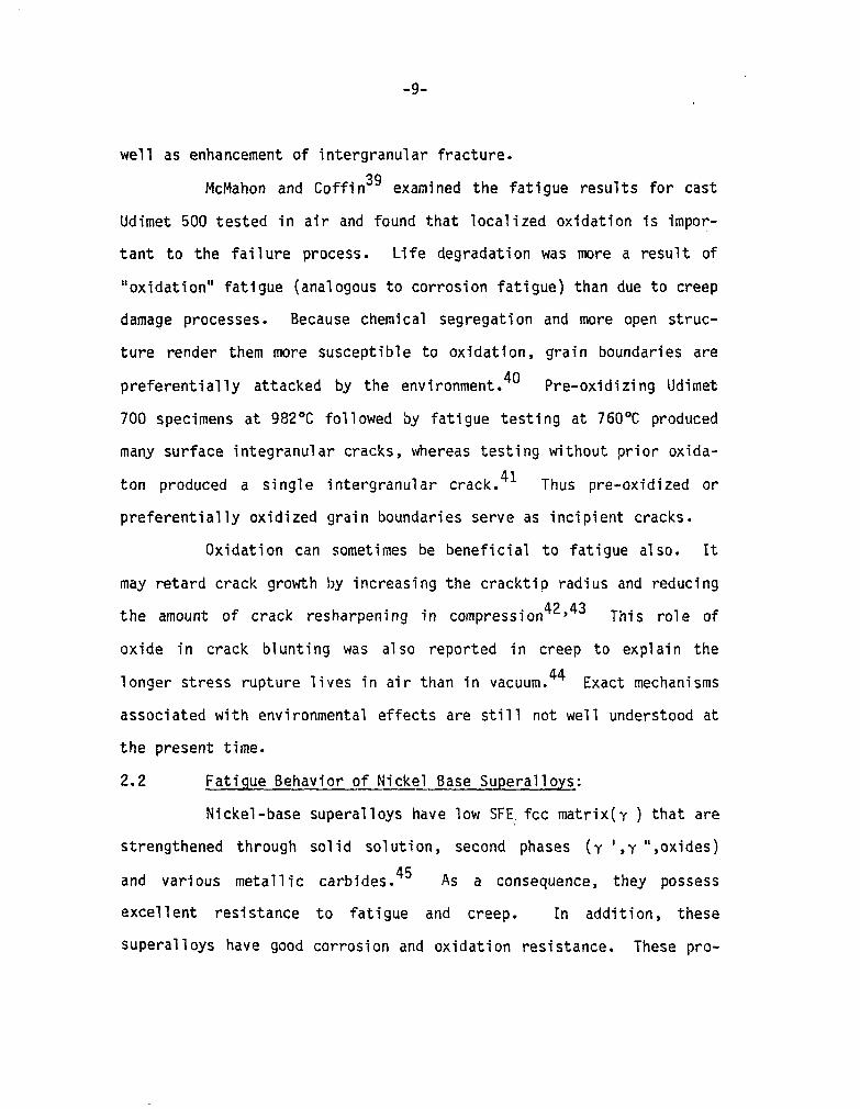
well as enhancement of intergranular fracture.
McMahon and Coffin3' examined the fatigue results for cast
Udimet 500 tested in air and found that localized oxidation is impor-
tant to the failure process. Life degradation was more a result of
"oxidation" fatigue (analogous to corrosion fatigue) than due to creep
damage processes. Because chemical segregation and more open struc-
ture render them more susceptible to oxidation, grain boundaries are
preferentially attacked by the environment." Pre-oxidizing Udimet
700 specimens at 982'C followed by fatigue testing at 760°C produced
many surface integranular cracks, whereas testing without prior oxida-
ton produced a single intergranular crack. 41 Thus pre-oxidized or
preferentially oxidized grain boundaries serve as incipient cracks.
Oxidation can sometimes be beneficial to fatigue also. It
may retard crack growth by increasing the cracktip radius and reducing
the amount of crack resharpening in compression 42,43 This role of
oxide in crack blunting was also reported in creep to explain the
longer stress rupture lives in air than in vacuum. 44 Exact mechanisms
associated with environmental effects are still not well understood at
the present time.
2.2 Fatigue Behavior of Nickel Base Superalloys:
Nickel-base superalloys have low SFE: fee matrix(y ) that are
strengthened through solid solution, second phases (y ',y ",oxides)
and various metallic carbides. 45 As a consequence, they possess excellent resistance to fatigue and creep. In addition, these
superalloys have good corrosion and oxidation resistance. These pro-

-lO-
perties are essential to high temperature applications in jet engines.
Fatigue behavior of nickel-base superalloys has been exten-
sively studied at both ambient and high temperatures. In these alloys
at low temperatures and high frequencies, slip is planar. Depending
on its size, Y' is either sheared or looped by dislocations. 46 As a
result, stage I cracking along slip band is the predominant initiation
mode. This has been observed in Udimet 700 by Wells et a1.,47 by
MerrickZ6 in Waspaloy, Inconel 718 and Inconel 901, in Astroloy by
Runkle, 25 in Udimet 710 by Moon et al., 48 and by Leverant et al. 4g in
Mar-M200 single crystal. Stage I initiation was also found at defect
sites by Gel1 et al.42 in Mar-M200 and by Menon et al. 5o in Rene' 95.
Duquette et al.,51 found that air environment had a profound
influence on stage I cracking in Mar-M200 single crystal at room tem-
perature. They explained its shorter fatigue life in air in terms of
the reduction in surface energy at the stage I crack tip due to oxygen
adsorption.
Studies on Rene' 9552 and Waspaloy53 by Antolovich et al. on
Astroloy by Merrick et a1.54 and on IN 718 by Mills et a1.55 showed
that their fatigue crack propagation (FCP) behavior is improved by a
microstructure that promotes slip planarity. In transgranular mode,
an increased slip planarity accelerates stage I cracking, but tends to
lower the fatigue propagation rate (FCPR) when oxidation effect is
only minor. In the temperature range of 550" to 65O"C, however,
Clavel et a1.56 observed greater frequency dependence of FCPR in
Inconel 718 than in Waspaloy due to the occurrence of intergranular
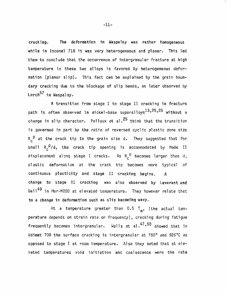
-ll-
cracking. The deformation in Waspaloy was rather homogeneous
while in Inconel 718 it was very heterogeneous and planar. This led
them to conclude that the occurrence of intergranular fracture at high
temperature in these two alloys is favored by heterogeneous defor-
mation (planar slip). This fact can be explained by the grain boun-
dary cracking due to the blockage of slip bands, as later observed by
Lerch57 in Waspaloy.
A transition from-stage I to stage II cracking in fracture
path is often observed in nickel-base superalloys13y25S26 without a
change in slip character. Pelloux et a1.25 think that the transition
is governed in part by the ratio of reversed cyclic plastic zone size
R,p at the crack tip to the grain size d. They suggested that for
small Rep/d, the crack tip opening is accommodated by Mode II
displacement along stage i cracks. As Rep becomes larger than d,
plastic deformation at the crack tip becomes more typical of
continuous plasticity and stage II cracking begins. A
change to stage II cracking was also observed by Leverant and
Ge114' in idar-M200 at elevated temperature. They however relate that
to a change in deformation such as slip becoming wavy.
At a temperature greater than 0.5 Tm, (the actual tem-
perature depends on strain rate or frequency), cracking during fatigue
frequently becomes intergranular. Wells et al. 47,58 showed that in
Udimet 700 the surface cracking is intergranular at 760' and 926OC as
opposed to stage I at room temperature. Also they noted that at ele-
vated temperatures void initiation and coalescence were the rate

-12-
controlling mechanisms. Fatigue studies on Udimet 500 and Rene' 80 by
Coffin et a1.3gs5g revealed that intergranular oxidation is the pri-
mary mechanism of crack initiation at 871OC. While the cracking
remained intergranular in Udimet 500, the fracture path changed to
stage II after one grain diameter in Rene' 80. Antolovich et
al 6o . also studied Rene' 80 with prior exposure under stress and found
a large reduction in fatigue life. They concluded that the most
severe form of damage was associated with environmental interactions
in the boundaries.
The effect of air environment on the high temperature FCP
for nickel-base superalloys has also been reported in the
literature. 61 In general, its effect on the FCP is to increase the
crack growth rate. The environment can, sometimes, promote intergra-
nular cracking, particularly when there is a decrease in frequency.
Hold time and frequency are found to have a significant
effect on fatigue behavior of nickel-base superalloys.
2.2.1 Effect of Hold Time:
In austenitic stainless steel most damage was observed with
tensile hold.31S33 From a study of Udimet 700 at 760°C with
interspersed dwell times, Wells et al. 27 noted that compressive dwells
were more harmful than tensile ones. The reason for this was
speculated to be the flatter shape of grain boundary voids and a
greater crack tip stress intensity when compressive holds were pre-
sent. Hold time studies by Coffin62 in LCF of Rene' 80 at 760°C
showed that compressive hold is more damaging than tensile hold. He

-13-
argued that a tensile hold accompanied by compressive mean stress is
beneficial to fatigue resistance and that compressive told with ten-
sile mean stress acts to reduce the fatigue life. A similar obser-
vation was also made by Feranish and McEvily63 with 2.25 Cr-1 MO
steel. They related the observed behavior to combined interactions of
oxide formation, spalling and surface deformation. In compression
following a tension hold the oxides spa11 to produce a new surface
free of macroscopic cracks while in tension following a compression
hold the oxides crack instead, creating localized stress con-
centrations that facilitate crack nucleation.
Sadananda and Shahinian 6446 studied FCP in Inconel 718 and
Udimet 700 and concluded that hold time effects depend on two factors;
environmental effects in relation to creep effects, and applied stress
intensity at the hold period in relation to threshold stress intensity
for creep crack growth Kthc. If the applied stress intensity during a
hold time is greater than Kthc, then hold time increases crack growth
rates due to both environmental and creep effects. If the stress
intensity is less than Kthc, environmental effects could still acce-
lerate crack growth if the creep deformation rate is sufficiently low.
But if the rate is high enough then crack tip blunting occurs which
arrests crack growth in spite of the environmental and cyclic effects.
2.2.2 Effect of Frequency:
Organ and Sell 43 observed that fatigue life in Udimet 700
tested at 760°C increased first as frequency increased from 2 to 600
cpm but decreased at 6 x lo4 cpm. They suggested that there were two

-14-
competing effects with increase in frequency. The increase in life at
first was because of the greater tendency to eliminate the effects of
creep and oxidation, thereby changing crack initiation from intergra-
nular to stage I. The reduction in life later was on account of pre-
dominant effect of increasing slip planarity which, in fact,
accelerated stage I cracking. In the case of Rene' 80, Antolovich et
al 67 . observed that at 871°C and 982°C with the damage controlled by
environmental effects, life increased with decreasing strain rate from
50 to 0.5 percent min-'. This was attributed to 'coarsening which
was beneficial in as much as it increased the ductility.
2.3 Damage Mechanisms in Rene' 95:
Rene' 95 is a high-strength wrought nickel-base superalloy,
developed by General Electric co.68 It has high potential for appli-
cation in the manufacture of compressor and turbine disks in advanced
aircraft engines. Like other nickel-base superalloys, Rene' 95 is
strengthened by Y ' precipitation [Ni3(A1,Ti,Cb)] and solid solution
lattice strain from the addition of MO, W, Co and Cr to Y ' matrix.
The carbides, act to prevent grain boundary sliding (creep damage) is
in the form of MC [(Ti,Cb,W)C]. The total weight percentage of Y '
forming elements (Al, Ti and Cb) is 9.5 - the number from which the
alloy derives its name.
A special thermomechanical processing, 69 involving warm
working the alloy in the two phase Y - Y' region at a temperature
below that of rapid recrystallization, imparts in Rene' 95 a duplex
microstructure, that consists of large warm-worked grains surrounded

-15-
by a fine grained recrystallized "necklace". Shamblen et a1.7o found
that in the range 538°C to 650°C, Rene' 95 with duplex microstructure
possesses mechanical properties superior to those of the same alloy
processed in the conventional way, having one hundred percent fine
grain structure. They ascribed this to greater crack propagation
resistance in air of the duplex structure by virtue of its large warm
worked grains.
Previous studies on tensile and fatigue deformation behavior
by Menon and Reimann 71,50 showed a more homogeneous deformation mode -
for necklace Rene' 95, as compared to the coarse planar mode occurring
in conventional superalioys. They believe that dislocation substruc-
ture in the warm-worked grains is very effective in dispersing slip
throughout the grain, thus forcing the material to deform homoge-
neously. They further suggest that the presence of necklace grains is
also responsible for such homogeneous nature of deformation.
Microtwinning 72 has also been observed as a mode of deformation
during tension and fatigue. The same authors suggested that it is
associated with the residual dislocation substructure in the warm-
worked grains.
In their LCF and creep study, Menon and Reimann 50'73 found
that the presence of MC carbides affects crack initiation of Cast +
Forged Rene' 95. At ambient temperatures crack initiation associated
with cracking or decohesion of MC carbides appeared to make fatigue
life shorter than that due to only slip band cracking. At 650°C the
presence of NC carbides that had undergone partial decohesion from the

-16-
fracture surface was seen near the stage I area. Typically the frac-
ture surface consisted of both stage I and stage II regions. Creep
results at 650°C in air showed higher minimum creep rates, shorter
steady state creep periods and lower rupture lives as compared to
those in vacuum. It was shown that air tested specimens with MC car-
bides on the surface were prone to surface cracking. Cracks generally
initiated and propagated intergranularly along the necklace region.
In contrast, specimens tested at 650°C in vacuum were not prone to
surface carbide cracking any more than when the carbides were inside
the specimen. The authors did not see any evidence of the propagation
of a single crack. Instead, they observed a mixture of intergranular
cracks and dimple rupture. These results demonstrate the strong
environmental effect on creep crack initiation in Rene' 95. Bashir et
al. 9 studied LCF of HIP + Forged PM Rene' 95 in air and found that a
great enhancement in life was associated with subsurface initiation.
This led them to conclude that there is a very significant environmen-
tal effect on the LCF of Rene' 95 at 65OOC. They indicated that the
fatigue life based on plastic strain was at least as great with ten-
sion hold time as for continuous cycling, and crack propagation tends
to occur by a boundary mechanism at least initially. As for con-
tinuous cycling, cracking always changed from transgranular to
intergranular. The transition was described in terms of a critical
combination of crack length and strain.
2.4 Damage Mechanisms in NARloy Z and Pure Copper:
NARl oy Z is an alloy of copper with slight addition of

-17-
silver and zirconium. This alloy was specially developed by Rockwell
North America Inc. 74 to meet the requirements of high thermal conduc-
tivity and fatigue resistance for rocket nozzle liners. By the addi-
tion of Zr to Cu-Ag alloy, uniform continuous precipitation, refined
grain size and improved ductility are attained. NARloy Z being a
proprietary material, there is no published report in the literature
of its fatigue behavior. However, literature on fatigue charac-
teristics of pure copper at elevated temperature is available.
Wigmore and .Smith75 studied LCF behavior of oxygen-free.
high conductivity (OFHC) copper between 400° and 6OOOC. They noted
the occurrence of grain boundary sliding and grain boundary migration
that produced preferential orientation of boundaries at 45' to the
stress axis. Cracking was found at triple points 'as a result of
stress concentration induced by grain boundary sliding. The cracks
increased in length with further fatigue and eventually link together
by ductile rupture causing final failure. Similar observations were
reported by Abdel-Raouf et al. 76 in OFHC copper at 650°C. They did
not see any migration at 3OOOC. Testing vacuum-cast copper (which has
a slightly higher purity level than OFHC copper) under the same
conditions, Wigmore and Smith 75 observed no triple point cracking.
Final failure was from what the authors identified as plastic instabi-
lity ,effect. Sidey and Coffin77 tested OFHC copper at 400°C at une-
qual strain rates to study the effects of wave shape. The fatigue
lifetime decreased by an order of magni.tude as the tensile going
strain rate was reduced from 1.7 x 10s3 s-l to 1.7 x 10B5 s-l at

-18-
constant cyclic period. Accompanying this reduction in lifetime was
a change in fracture mode from transgranular in the case of fast-slow
tests to intergranular (internal cavitation) for slow-fast tests.
2.5 Fatigue Life Prediction Models:
Criteria for life prediction is generally established in two
ways: (a) by consideration of cyclic and time-dependent effects as
separate phenomena, and combining the damage function by assuming a
linear damage accumulation rule, for each determined separately as in
the SRP model; or (b) by consideration of the cyclic and time effects
as a single process expressed in terms of several variables, including
the strain rate or frequency of the cycle as in FS, Ostergren and DR
models. Each of these models is discussed in the following sections.
2.5.1 Strain-Range Partitionins Model:
The strain-range partitioning (SRP) concept1978 is an exten-
sion of the Coffin-Manson law (which is valid at room temperature) to
high temperature by including the interaction of time-dependent ine-
lastic strains (creep) and time-independent inelastic strains
(plasticity). The inelastic strain range consists of four components,
* EPP, * EpC, * Ecp, * Ecc* From these, four inelastic strain-life
relationships are constructed. Then the interactive law in the
following form is invoked;
F F PP +
F pc + Fcp + cc =
1 -_ - -
NF NPP PC cP %c N
(1)

-19-
where F.. 13 = fraction of the ij inelastic strain component
N ij = life calculated from the pre-determined strain-life
relation of ij assuming all of the inelastic strain
to be of the component of interest.
N = predicted overall life.
It should be noted that except for the AC PP
vs Npp curve
all other relationships are computed assuming that eq. (1) is valid.
Clearly this introduces an element of redundancy into the scheme.
The applicability of the SRP model was demonstrated with the
following systems: AISI 316 at 705OC, 2.25 Cr-1Mo steel, A286 and
H-13 steel at 595OC, Incoloy 100 at 925OC, T-111 at 115OOC.
2.5.2 Frequency Separation Model:
Modifying the Coffin-Manson law by introducing a frequency
term to account for a creep effect, Coffin 34 proposed an expression,
*“p (b v k-l)o = c
(2)
This modification though it incorporates time dependence factor, is ina-
dequate to account for the behavior of unbalanced loop. This is
resolved in the frequency separation (FS) nodel,2 by application of
the elastic strain and life relationship.
*Ee = ha = A Acpn v kl = A’Nf+’ v kl
E
and determination of the stress range of unbalanced loops by
(3)

-2o-
A vc kl
%F = &,Fs =p [(-I-, Vt kl
+Q I&p”
The cyclic life is then determined from
kl'h'
Nf= (- A' )1/e'
a-) *'SF 2
where AosF = stress range of a slow-fast loop
(4)
(5)
Q/2 = tension-going frequency
8' =nS
kl' = kl - (k-1$
A more general form which incorporates plastic range, tension going
frequency and the loop time balance as important variables, is given
by
Nf = DAEpa V b
vc c t (,I (6) t
It should be noted that the stress range in eq. (4) is
0 really a fictitious term which, is, in reality, determined from tw
experiments.
Examples of systems with successful application of FS mode
are AISI 304 at 593OC; and AISI 316 at both 566°C and 704°C.
1
2.5.3 Ostergren Model:
Ostergren 3,79 considered LCF to be essentially a problem of
crack propagation and assumed that only the deformation which occurs
when the crack is open contributes to crack propagation and thus to

-21-
fatigue damage. A damage function aTAsp, proportional to the net ten-
sile hysteretic energy, was then introduced as a measure of damage.
This results in an equation
6TkpNfB = c
similar to Coffin-Manson law. In order to account for hold time and
frequency effects on life, time-dependent damage equation was deve-
loped, similar to Coffin's frequency modified equation:
(7)
For time-dependent, wave shape independent condition, the frequency is
the inverse of the cycle period L, = l/(~~ + Tt + .rc), whereas in the
case of time-dependent, wave shape dependent situation, v = l/(~, +
Tt - 'c) and v= 1/'o for rt 5 Tc. In terms of mechanisms, in the
former case, it hypothesizes that time dependent damage results
primarily from environmental reacitons (oxidation), while in the
latter case, it accounts for the greater time-dependent damaging
effect of unreversed tensile creep deformations.
Systems to which Ostergren model is applicable are IN 738
and Rene' 80 at 871°C (time-independent); Cr-MO-Y at 538°C
(time-dependent, wave shape independent) and AISI 304 at 538OC
(time-dependent, wave shape dependent).
2.5.4 Damaqe Rate Model:
The damage rate mode14'80 assumes that LCF is primarily a
process of propagation of pre-existing microcracks and the crack

-22-
growth rate da/dt is governed by the strain and strain rate as
follows:
da = - (under tensile stress)
dt acl Ep 1
m , lp , k (under compressive stress) (9)
(8)
T, C, m and k above are material parameters that are functions of tem-
perature strain rate, environment and the metallurgical state of the
material. Usually the transition in these parameters is associated
with transitions in the fracture morphology, e.g. from a predominantly
transgranular to a predominantly intergranular mode. Cyclic life is
obtained by integrating the above equation under the given boundary
conditions. For continuous cycling, the following expression is
obtained:
Nf = [(m+l)/4A] (AE~/~)-(~') (;P)‘-~
where A = (T+C)/2 Mac/a,)
For hold time tests, it is
l/Nf = [4A/(Wl)] (AEP/Z)~+~ (8p)k-1 + j&Pmaxl m
(10)
(11)
lotH [2A/(l+C/T)I !$I k dt + I ‘pminl m
IotH [2A/(l+T/C)I I;,1 kdt

-23-
This model has been successfully applied to AISI 304, AISI
316, Incoloy 800 and 2.25 Cr-1Mo steel at various temperatures.
2.5.5 Antolovich's Oxidation Model:
Assuming that there is a combination of environmental
penetration and stress at which a microcrack can form,
Antolovich67S81 proposed an oxidation model which can be basically
expressed in terms of the equation:
cJ max . i
a P = co i
0 max where i = maximum stress at initiation
"i = oxygen penetration at initiation
P,CO = material constant
Further, the oxygen penetration for an initiated crack may be computed
assuming that parabolic kinetics are obeyed:
'i = a~i
where a = geometric constant
ti = time to initiation
D = diffusion constant
The applicability of this model can be examined by taking the time for
crack initiation in a given test and comparing it to the shortest
crack initiation time for a given set of tests:
ai/ejo = (tj/t’i) M where aio = initiation crack length for shortest test
to i = time corresponding to eio

-24.
In applying the oxidation model successful correlations have
been obtained from systems: Rene' 80 at 871OC and 982"C, Rene' 77 at
929OC, on Nimonic 90 and Mar-MOO2 at various temperatures.

-25-
3. EXPERIMENTAL
3.1 Materials and Test Procedure:
All the specimens used in this study had already been tested
by Mar Test for the AGARD SRP program. The Rene' 95 specimens were
tested under the direction of Air Force Materials Laboratory and the
NARloy Z specimens under the direction of NASA Lewis Research Center.
A brief description of the treatments and testing procedures, as
reported82a83, ' is given below.
3.1.1 Materials Processing and Heat Treatment:
The chemical compositions and tensile properties of both
materials are summarized in Tables I and II. Vacuum induction melted
and vacuum arc remelted Rene' 95 ingot about 22.8 cm in diameter was
given a homogenization anneal in the range 990°C to 1163OC for 3 hours
and then furnace cooled. Two pancakes taken from the ingot were
forged in the temperature range 1043OC to 1137°C to reduce them to
about 40-50 percent above the final thickness. This was followed by a
recrystallization anneal at 1163°C for one hour and cooling to 900°C
at a rate greater than 93.3OC per hour. This results in uniform
grains varying in size between 0.064 and 0.127 mn. Final reduction
was done on these forgings at 1080°C to 1109OC. This imparts suf-
ficient deformation to produce dynamic recrystallization or the
"necklace" in the grain boundary region and a heavy dislocation den-
sity in the recrystallized grains. They were then partially solution
treated at 1093OC and aged at 760°C for 16 hours to produce a Y '

-26-
structure in the maxtrix. Specimens were taken in the tangential
direction of the pancake.
NARloy Z was furnished in the centrifugally cast form.
Following hot rolling it was solution annealed at 927OC and aged at
482°C to let second phases precipitate out. The final material was in
the form of a rectangular bar, 23.2 cm long x 5.1 cm x 4.1 cm.
3.1.2 Test Procedures:
Hourglass specimens with both buttonhead and threaded ends
shown in Fig. l(a),(b) were used. The latter were whole Rene' 95,
while the former were frictionally welded withIncone 718, 1.27 cm
away from the buttonhead. Low cycle fatigue tests were conducted in
air at 650°C, using a servo-hydraulic testing machine. For each test,
diametral strain was controlled and then converted to total axial
strain which was reported. All testing was done in a fully reversed
mode (RE = -1, A = ~0 , where RE = maximum strain/minimum E
strain; A E
= strain amplitude/mean strain). To test the SRP model
for high temperature LCF, the test types were designed as shown in
Fig. 2. Continuous cyc7ing tests were run at frequencies of 20 and
0.05 cycles per minute (cpm), using triangular waveform. For cyclic
strain hold tests the ramp rate was the same as for 20 cpm tests while
the maximum strain was held for either 1 or 10 minutes under tension
(cp), compression (PC) as well as tension-compression (cc). The
strain and stress waveforms for these tests are shown in Fig. 3. In
cyclic creep tests, the load was ramped to a prescribed value and was
then held allowing the specimen to creep to a fixed diametral strain

-27-
limit before reversing the load. In unequal frequency (strain rate)
tests, slow-fast tests were carried out at frequencies of 0.05 and 20
cpm for tensile going and compressive going modes respectively. For
fast-slow tests the reverse scheme was employed.
Threaded hourglass specimens shown in Fig. l(c) were used in
the study of NARloy Z. All tests were performed at 538°C in high-
purity argon (oxygen content less than 0.01 percent by volume)
chamber. 3000 ppm of hydrogen was added to provide a slightly
reducing environment for additional protection of the specimens.
Testing procedure was the same as cited above for Rene' 95. The test
matrix was also the same with the exclusion of cyclic creep tests.
The strain rates used in continuous cycling tests ranged from 0.004 to
1.0 percent set -1 . For hold time tests the dwell period was 5
minutes. In unequal strain rate tests, strain rates employed were
l/0.04, 0.04/l, 0.004/l and 0.0007/l percent set -' (tension
going/compression going).
3.2 This Investigation:
In this study, detailed metallographic examinations were
done on selected specimens of Rene' 95 and NARloy Z tested under con-
tinuous cycling and with strain hold times. The total strain ranges
for Rene' 95 were from 1.3 percent to 0.9 percent. For NARloy Z
strain ranges were 2.6 percent and 0.9 percent.
3.2.1 Scanning Electron Microscopy (SEM):
Failed specimens were cut near the fracture surface after
ultrasonic cleaning in acetone. The fracture surface and gage section
-28-
were examined with a 25 KV Cambridge Steroscan 600 SEM to characterize
initiation sites, mechanisms of crack advance and formation of secon-
dary cracks.
3.2.2 Metallography:
Following SEM examination the gage portion was sectioned
longitudinally through planes containing the initiation sites and the
specimen axis. These longitudinal sections were cold mounted with
addition of the Alumina to the epoxy to prevent the occurrence of
round edges during polishing. Standard techniques were used for
metallographic preparation. Polished Rene' 95 specimens were either
chemically etched with Kalling's reagent (29 CuC12, 12 ml HCl (37%
concentration) 180 ml ethanol) or electroetched with a solution of 45
percent acetic acid (99.7% concentration), 45 percent butyl cellusolve
and 10 percent perchloric acid (70% concentration) at 20°C and 3V in
Buehler polishing unit. The specimen surface in reaction with the
solution is a circle with 1 cm in diameter. NARloy Z specimens were
etched either with 5g FeC13, 15 ml HCl and 100 ml ethanol after
polishing or by adding several drops of NH30H (29% concentration) to
0.05 11 Alumina polishing abrasive. Etched specimens were then exa-
mined with optical microscope/SEM to determine the nature of secondary
cracking, to detect internal cavitations and to evaluate the impor-
tance of carbides and intermetallic compounds on microcrack formation.
The same techniques were also used to characterize the initial struc-
ture of both materials.

-29-
3.2.3 Transmission Electron Microscopy (TEM):
Small wafers were cut perpendicular to the specimen axis as
close to the fracture surface as possible. These wafers were electro-
polished by standard twin jet technique into thin foils. Mixture of
250 ml methanol, 12 ml perchloric acid and 150 ml butyl cellusolve was
used in electropolishing Rene' 95 at -3OOC and 30V. For NARloy Z a
solution mixture of 100 ml HN03 (70% concentration) and 200 ml metha-
nol was used at -25OC and 15V. The foil surface in reaction with the
solution is a circle with 3 IMI in diameter. The low temperature was
attained by using a Cryscool cooler. These thin foils were examined
with a 200KV JEOL JEM-200A TEM to characterize the detailed
microstructure and the deformation behavior of each system.

-3o-
4. RESULTS AND DISCUSSION
4.1 Rene' 95:
4.1.1 Initial Structure:
The microstructure of Rene' 95 forgings has been charac-
terized earlier by Menon. a4 The undeformed structure of as received
Rene' 95 specimens observed in this study was the same as reported by
Menon.
Fig. 4 shows the typical necklace structure of Rene' 95.
The warm worked grains of average grain size 75u, are surrounded by a
necklace of fine recrystallized grains about 4~ in size. Intermediate
sized y' precipitates (size 0.5~) are uniformly distributed in the
warm worked grains, giving a dark shade to these grains. MC carbides,
high in Ti, Nb and W are also randomly scattered through the material.
Details of the necklace region are revealed in the scanning micrograph
of Fig. 5. The grain boundaries of recrystallized necklace regions
are decorated with large Y' (size 1~). These are apparently larger
than those inside the warm worked grains on the adjacent sides because
of the partial solutioning. The white particles at the boundaries
between the warm worked grain and the necklace region, are the MC
carbides which are in relief after electroetching. Fig. 6 shows a
transmission micrograph of the necklace region. The fine y ' (size
0.05~), appearing as small light areas in the background, are, in
fact, distributed evenly throughout the material. The recrystallized
fine grains are seen to be free of dislocations. Many of them were

-31-
twinned as shown in Fig. 7. Here, a warm worked grain is on the left
while the necklace region is on the right surrounding it. 'In the warm
worked grain, the residual dislocation substructure introduced during
the final forging is clearly evident, The intermediate sized Y ',
providing a barrier to impede recrystallization or realignment of
dislocations into polygonal cells, serves to stabilize the structure.
4.1.2 Low Cycle Fatigue Test Results:
The stress behavior of Rene' 95 during fatigue testing is
available in the technical report AFWAL-TR-80-4075. For continuous
cycling under total strain control, initially for a short period of
time, it exhibited strain hardening. This was followed by strain sof-
tening for the rest of the life. In hold time tests, stress usually
relaxed rapidly to 80-90 percent of the maximum stress in the first
fifteen seconds (see Table III) but remained almost constant
thereafter. Won-zero mean stresses 85 were noticable, especially in
tests at the lower strain ranges and with longer hold times. !n the
case of tensile hold tests the maximum tensile stress decreased with
cycles while the maximum compressive stress increased, i.e., the
hysteresis loop shifted in compressive direction. As a result, the
mean stress continued to shift in the compressive direction throughout
the life. Shifts to a tensile mean stress occurred for tests under
compressive hold but they were less dramatic.
The results of LCF tests on Rene' 95 tested under continuous
cycling and with strain holds at 650°C are summarized in Table 'III.
All the stress and strain data listed were values at half life. Note

-32-
that the elastic component was much greater than the plastic one.
This, in fact, is a common phenomenon in nickel-base superalloys in
the strain range of general studies. The mean stress effects cited
above are demonstrated in this Table by the differences between maxi-
mum tensile and compressive stresses.
Coffin-Manson diagram is shown in Fig. 8. On the basis of
plastic strain range, tensile hold and continuous cycling, in general,
appeared to exhibit longer life than compressive and balanced (both
tensile and compressive) holds. Although differences in life did
exist between different cycle types, they did not seem to be very
significant. The trend in the large shift mentioned earlier, of the
maximum tensile stress developed during hold time with respect to con-
tinuous cycling, is shown in Fig. 9. At a given plastic strain range,
compressive hold developed higher tensile stress than continuous
cycling. Tensile and balanced holds had lower values instead. This
shift of tensile stress was especially marked for tensile hold at
lower strain ranges. The life of tensile hold here, is greater than
that of continuous cycling as shown in Fig. 8. This seems to imply
that besides the plastic strain range, stress also should be taken
into account in determining the fatigue life. This is due to the
marked effect of hold time on the maximum tensile stress. This point
will be discussed in more detail later.
4.1.3 Metallography:
(i! Continuous Cycling (20 cpm)
At higher strain ranges multiple crack initiation was
-33-
observed. A typical example is shown in Fig. 10. As apparent in Fig.
10(a), there is a transgranular initiation followed by a mixed mode
of propagation. Noting that intergranular cracking, in the case of
necklace Rene' 95, means fracture path along the grain boundaries in
the necklace regions, the grain boundaries on the fracture surface
are, in fact, those of small recrystallized grains 4~ in size. At
higher magnification, in Fig. 10(b), striations can be seen in the
transgranular crack propagation region near the origin. MC carbides
are readily observed on the fracture surface. Here, one MC carbide is
situated right at the origin, \ti-ich was probably responsible for ini-
tiation of the crack. Two other MC carbides are also seen near the
origin, but apparently had been cut through during crack propagation.
This was the case in most other crack initiation regions. Fig. 11
shows another crack initiation region. Here, the crack probably had
initiated intergranularly but followed by predominantly transgranular
propagation. The striations are clearly visible on the fracture sur-
face and are very brittle in nature. From examination of the longitu-
dinal section, it is seen that majority of the cracks initiated
transgranularly. In the case of crack growing more than one grain
depth, it often changed directions upon crossing the necklace regions
or as it travelled across a singie warm worked grain (Fig. 12). Vote
that the texture of the specimens is such that warm worked grains
were elongated in the direction of specimen axis. This, apparently,
made the crack path more tortuous. Thus, grain boundary cracking is
impeded.

-34-
-A little away from the initiation region, crack propagation
is still by a mixed mode while faceting was frequently found in the
warm worked grains (Fig. 13). Menon and Reimann50a71 have reported
earlier, observation of faceting on tensile and fatigue fracture sur-
face of necklace Rene' 95. They speculated it to be due to the
microtwinning in the warm worked grains. Oblak and Owczarski6' have
also previously reported, faceting on tensile fracture surface of
thermomechanically processed Udimet 700, but they ascribed it to a
possible path of failure along (111) slip planes. More recently,
Mills86 observed facets on the fracture surface of Inconel X-750
following tensile deformation. From examination of the longitudinal
section, it appeared to have failed along well-defined slip traces.
Therefore, he believed that the facets were a result of separation
along dislocation channels which, in fact, are slip bands formed by an
extensive planar slip of dislocations. For the case of necklace Rene'
95, Mills' reasoning seems to be more applicable. This point will be
discussed later in the section on deformed microstructure.
At lower strain ranges, just as at high strain ranges,
cracks often initiated at surface connected MC carbides, as shown in
Fig. 14. Initial crack propagation appeared to take place transgranu-
larly in the warm worked grains. Whenever it encountered the necklace
region, the crack changed its path to follow the grain boundaries.
This dual mode of cracking seems to be more extensive and distinct
with decreasing strain range. Fig. 15 shows the region of crack ini-
tiation and initial propagation of a specimen tested at 0.9 percent

-35-
total strain range. The warm worked grains were clearly delineated by
the necklace surrounding them. In the warm worked grain where the crack
initiated, the crack surface appeared to be very smooth such that even
slip traces can be seen on the fracture surface. Although the grain
did show slip band formation, there was no evidence to suggest that
initiation was due to cracking along slip bands. Rather, a surface-
connected MC carbide situated at the origin clearly suggests that the
crack had initiated at MC carbide but not along slip band. Following
the dual mode of cracking was the normal mixed mode which included
those features like striations and facets in the warm worked grains.
In a previous study 73 on crack initiation in necklace Rene'
95 at room temperature, it was found that cracking of MC carbides
seemed to play a significant role. In this study also, cracking of MC
carbides was seen quite often on the gage surfaces of all the speci-
mens examined. An example is shown in Fig. 16(a), depicting cracking
of surface carbides. Fig. 16(b) shows two cracks which had originated
from cracking of MC carbides and further propagated into the matrix.
Thus, it can be concluded that crack initiation was due to cracking of
the surface MC carbides, as those present in the crack initiation
region on the fracture surface.
Some of the MC carbides had fractured inside the specimen
during deformation (Fig. 17). In specimens tested at higher strain
ranges, internal cracks were occasionally seen (Fig. 18). Since the
crack did not follow the path of grain boundaries, it could not
possibly be due to the effect of creep. It is likely that the crack

-36-
had initiated at an internal MC carbide and further propagated
transgranularly.
On the gage surface of the specimens slip offsets were some-
times observed (Fig. 19). However, no crack was found to initiate
along these slip bands. Occasionally the edges of the fracture sur-
faces were seen to be parallel to the slip offsets in the crack propa-
gation region (Fig. 20). This, along with the facets found on the
fracture surfaces indicate that slip band cracking did play a role in
crack propagation. In view of the fractography it seems possible that
extensive slip took place only near crbides and eventually crack
initiation occurred in slip bands which contained carbides.
(ii) Deformed Microstructure:
Although the TEM study was somewhat limited, some features
which are typical and representative were observed in the deformed
microstructure. In the warm worked grains, besides a general increase
in dislocation density, microtwins and slip bands were also
present87 as shown in Fig. 21. Menon and Reimann50y71 have reported
that the dislocation substructures retained in the warm worked grains
was very effective in dispersing slip. This in turn, prevented early
formation of intenGslip bands and forced the deformation to take
place more homogeneously, as compared to the coarse planar slip that
occurs in conventional superalloys. This reduced planarity of slip is
also illustrated in Fig. 21. Here, slip bands (parallel to (111)
planes) are closely spaced and often end at the interior of the grain
rather than being wide spaced and crossing the entire grain.The regions

-37-
between slip bands also had a high denisty of dislocations, thus
obscurring the prominence of the slip bands.
In the last section, a question was raised as to whether the
facets observed on the fraturc surfaces were. due to microtwinning or a
result of planar slip in the warm worked grains. It was shown that
the width of microtwins in Fig. 21 was much smaller than the hei.ght of
facet steps shown in Fig. 13. Therefore, the facets cannot possibly
be a result of microtwinning. Rather, it is believed that with
increasing cycles the slip bands which were not intense in the
beginning tend to become more intense. This is true especially in
those ahead of the crack tips. Therefore, cracking along slip bands
(facets) was always seen in the regions of crack propagation.
The deformation in the necklace grains was planar which was
also relatively homogeneous in that the interspacing between slip
bands was very small (Fig. 22).
(iii) Effect of Hold Time:
When hold time was introduced into each cycle (irrespective
of the nature of the hold), fractography revealed an intergranular
crack initiation and early crack propagation except at lower strain
ranges. Fig. 23 illustrates this intergranular cracking in specimens
tested at 1.4 percent total strain range under tensile, compressive
and balanced holds respectively. A mixed mode of cracking was again
observed away from the origin with occasional facets and striations,
as shown in Fig. 24, in the warm worked grains. On the longitudinal
section, as shown in Fig. 25, most of the secondary cracks seen were

-38-
initiated in the necklace regions (grain boundaries). Fig. 26 shows a
crack which although was initiated transgranularly, propagated predo-
minantly along the necklace regions before meeting a warm worked
grain. Due to the tortuosity of the grain boundaries, a pure
intergranular cracking was hardly seen.
At lower strain ranges, the initiation of cracks again
appeared to be associated with MC carbide cracking. The dual mode of
cracking, i.e. transgranular in the warm worked grains and intergranu-
lar in the necklace grains, was again observed in all types of holds.
It was particularly marked in tensile hold, as shown in Fig. 27.
At the interior of the specimens, the damage was not pro-
nounced, indicating that creep did not play an important role in the
damage process of hold time tests. Considering the tendency for'the
crack to initiate intergranularly on the surfaces with the introduc-
tion of hold time], a possible involvement of environment appears to be
implied. In Fig. 8 it was already shown that tensile hold resulted in
life not less than that in continuous cycling. This, then, suggests
that the cracking mode (initiation and early propagation) became
intergranular under tensile hold in contrast to transgranular mode
under continuous cycling. However, the life did not decrease
correspondingly. It is clear that in the case of necklace Rene' 95, a
decrease in life is not necessarily associated with intergranular
cracking. The most likely reason for this is the role of tortuous
morphology of grain boundaries mentioned earlier, in slowing down the
fracture process when the crack path follows grain boundaries.

-39-
As shown in Fig. 8 at a given plastic strain range the dif-
ferences in fatigue life between different cycle types became substan-
tial at lower strain ranges. However, the mode of cracking still
appeared to be very similar to that seen above. This then, implies
that differences in fatigue life in this case resulted probably from
the different crack propagation rates between the various cycle types.
Recently Coffin 88 has described the importance of mean
stress effects in terms of the transition fatigue life, i.e. the life
where the elastic and plastic strains are equal. There the life
exceeds the transition fatigue life, the greater the mean stress
effect. The transition fatigue life for Rene' 95 at 650°C has been
determined to be about 72 cycles.8g Consequently, all the tests in
this study were conducted above the transition fatigue life. Hence,
consequences of the maximum tensile stress (or mean stess) should be
considered. This is particularly important when considering the fati-
gue life controlled by crack propagation, assuming that microcracks
have nucleated early in life. Although the plastic strain range
remains the same for different cycle type tests, the maximum tensile
stress can, indeed, influence the local plastic strain at the crack
tip. Higher the maximum tensile stress, greater is the crack opening
and faster is the crack growth. This may be the case in Rene' 95,
since cracks often initiated at MC carbides.
Previously, in the case of LCF hold time behavior of Cast
Rene' 80 at a plastic strain range of 0.32 percent, Lord and
Coffin62 have already demonstrated that mean stress effects could

-4o-
account for the life behavior in a qualitative sense. The same
conclusion can also be drawn in this study. Further, a quantitative
dependence of life on maximum tensile stress is shown in Fig. 28. The
data seem to fall generally onto three lines, corresponding to the
three respective tensile hold times - 0, 1 and 10 minutes. The
observed behavior not only illustrates the important role of the maxi-
mum tensile stress in determining the fatigue life, but also
demonstrates the influence of tensile hold time on fatigue life.
Whether this behavior has any mechanistic basis is not known at the
present time. However, it tends to imply that crack growth is pro-
moted by introduction of a tensile hold.
Previously Wright and Anderson" found that in directionally
solidified Rene' 120, under strain controlled testing, the developed
stress levels and the lives varied with orientation. This was because
of the dependence of the elastic modulus on orientation.
Consequently, they found that most of their LCF data for various
orientations fit one master curve, when the maximum tensile stress
rather than total strain range was plotted against life. Considering
LCF as mainly a process of crack growth the authors recommended using
maximum tensile stress as a life prediction parameter.
In this study, due to the effect of the two variables,
plastic strain range and maximum tensile stress, comparison of the
lives between cycle types became difficult. On the basis of maximum
tensile stress alone, life seems to depend only on tensile hold time.
Therefore, quite contrary to the result shown in Fig. 8, simply on the

-41-
basis of plastic strain range, life of tensile hold is comparable to
that of continouous cycling but greater than that of compressive hold.
Although the relative contribution of these two variables in deter-
mining the fatigue life is not clear, however, the effect of maximum
tensile stress is distinct and has to be taken into account in any
life prediction scheme.
4.1.4 Applicability of Fatigue Model:
With the experimental data in this study for necklace Rene'
95 at 65O"C, four fatigue life models were evaluated earlier. a' Their
applicability and limitations in predicting lives corresponding to
various cycle types are summarized in Table IV. The established criterion
for accepting predicted lives was that predicted lives should be within a
factor of two of the observed lives. If the predicted vaiues were
greater than twice the observed lives, the model was considered to
overpredict. By the same token, when it *tias less than half the
observed lives, the model was regarded as underpredicting the lives.
In general, all the models showed a tendency to underpredict
lives of tensil hold, Also, in the case of compressive hold, with
the exception FS model, they all resulted in overprediction. As
mentioned earlier under tensile hold the creep effects (internal
damage) in Rene' 95 were almost absent. But,
-42-
because of the comparatively lower maximum tensile stress, life of
tensile hold was greater than that of compressive hold. Thus,
underprediction of the lives by these two models for tensile hold and
overpredition for compressive hold is understandable.
In applying Ostergren's model, the time-dependent, wave shape
independent situation was considered, where v = l/(r o + ~~ + T c)
(cyclic frequency). Even though in this life prediction scheme, maxi-
mum tensile stress was incorporated into the damage term, predic-
tion of lives at lower strain ranges and under longer hold times was
difficult. It should be noted. that at lower strain ranges higher
degree of scatter in the data is always present in part due to the
uncertainty in the experimental procedures. This uncertainty in turn
makes accurate life predictions more difficult. from this study, it
is recognized that both plastic strain range and maximum tensile
stress can be the variables controlling the fatigue life. Interaction
between these two in relation to the different cycle types is not ade-
quately understood at the present time. Further, the time dependent
factor in determining life seems to be the tensile hold time rather
than the cycle period (reciprocal of cyclic frequency) used in
Ostergren's model. Thus, question still remains as to the validity of
the damage term employed in the Ostergren's model.
Overall, the LCF behavior of nickel-base superalloy Rene' 95
\qas seen to be quite different from that of stainless steel. However,
it was similar to that of Rene' 80" with no pronounced creep effect
under tensile hold. The life prediction models that associate creep

-43-
with tensile hold were rendered inapplicable. Due to the limited
information available in this study, no attempt was made to develop a
suitable life model to describe the LCF behavior of Rene' 95. It is
believed that any life prediction scheme, in order to be applicable,
should incorporate the fact that tensile hold promotes crack propaga-
tion and the effect of maximum tensile stress. Before attempting to
develop any model, more work needs to be done in estimating the rel a-
tive proportion of life corresponding to crack initiation and propaga-
tion as well as the possible involvement of environment, which was
reported in creep for Cast + Forged Rene' 95'3 and in fatigue for HIP
+ Forged Rene' 959, with respect to different cycle types.
4.2 NARloy Z:
4.2.1 Initial Structure: --
The initial structure of NARloy Z is shown by the optical
micrographs in Fig. 29. The average grain size was determined as 150~~
( ASTM No. 3) by linear intercept method. The intermetallic compound
resulting from the addition of Zr to the Cu-Ag entectic system is
visualized and has been identified as Cu-lOAg-22.5 Zr with a tetrago-
nal structure. 74 Two types of precipitates in the Cu rich matrix are
shown in Fig. 30(a) transmission micrograph. One of these is larger,
and tends to grow on certain crystallographic planes, the other rela-
tively small and evenly distributed in the background. Analyzing the
diffraction pattern shown in Fig. 30(b) using the selected area
diffraction technique, the former ts identified as Ag which gives rise
to rings and the latter, Cu20 (cuprous oxide) which gives rise to

-44-
superlattice spots. Ag precipitates, having FCC structure, normally
are found in the form of plates, lying parallel to (111) or (100) pla-
nes of the Cu matrix with random directions. " This is the reason why
rings, corresponding to Ag, are present in Fig. 30(b) under (111)
diffraction. Cup0 precipitates, having C3 cubic structure, 91 exhibit
orientation same as the Cu matrix. The slightly different lattice
parameters make both precipitates semi-coherent. Rockwell
International Inc., who developed this material did not report the
presence of Cu20 which is probably a result of internal oxidation.
4.2.2 Low Cycle Fatigue Test Results:
Table V summarizes the results of LCF tests at 538OC under
continuous cycling and with strain holds. The higher ductility and
low strength of NARloy Z is reflected by the plastic component much
greater than the elastic one. The life, therefore, was dominated by
the former and was truly in the LCF regime. For continuous cycling
tests, stress range was very sensitive to strain rate especially in
the high strain range. For hold time tests maximum tensile stress rfas
only dependent on the strain range and almost independent of the cycle
character. Stress relaxation during hold time was very pronounced in
NARloy Z. This is indicative of significant creep and/or creep crack
growth, i.e. the creep effect may have played an important role in the
damage process. The Coffin-Manson diagram is shown in Fig. 31.
Apparently cyclic life decreased with decreasing strain rate under
continuous cycling. Further, tensile hold was the most detrimental
among the cycle types in interest. Life in the case of compressive

-45-
hold was comparable with that of continuous cycling at high strain
rate of 1.0 percent set-'. It is worthwhile noting that the dif-
ference in lives between cycle characters are much greater in NARloy Z
than' in Rene' 95.
4.2.3 Metallography:
(i) Effect of Frequency:
In specimens tested at high strain rate, integranular sur-
face cracks had initiated and grown two or three grains in depth by a
boundary mechanism before changing to transgranular. Such a tran-
sition from intergranular to transgranular is shown in Fig. 32(a).
The striations are clearly seen in the region of transgranular crack
propagation (Fig. 32(b)). No significan t differences were seen in
fracture details between high strain range (2.6 percent) and low
strain range (0.9 percent) tests. They both had a multiple crack ori-
gins and final rupture of the specimens took place in the center of
the overload region. A number of grain boundaries on the gage surface
had undergone decohesion. As shown in Fig. 33, cracking of some of
these were connected with the fracture surface. From examination of
the longitudinal section, it is seen that most of these intergranular
surface cracks either had ceased growing right after initiation as in
Fig. 34(a) or had grown two or three grains in depth (Fig. 34(b)).
The fact that boundary cracking is limited to regions near the surface
seems to imply that it is was probably either environmentally assisted
or due to a creep effect (where the grains are unconstrained and
sliding is easier). The role of environment will be discussed in

-46-
greater detail later. Fig. 34(c) shows an intergranular surface crack
which had propagated like the main crack, transgranularly into the
matrix.
Away from the surface, intergranular damage in the form of
wedge type cracking (Fig. 35(a)) and cavitation (Fig. 35(b)) was
observed at high strain range. However, considering the fact that the
main crack propagated by a transgranular mode, such damage does not
seem to play an important role as far as crack propagation is con-
cerned.
As the strain rate decreased, cracking became predominantly
intergranular and striations were absent from the fracture surface, as
shown in Fig. 36. Extensive grain boundary cracking on the gage sur-
face (Fig. 37) was again observed in low strain rate tests.
Discoloration of the specimens and obscuring of the fracture details
in Fig. 36 indicate that oxidation had occurred during testing. The
oxidation is probably due to the reaction of the trace of oxygen
and/or moisture in the Argon environment. Thus even though the
environment was supposed to be jnert, in reality; environmental con-
tamination was still present. As seen in Fig. 37, preferential grain
boundary oxidation is more pronounced in this case than in high strain
rate tests (Fig. 33). Meanwhile, on the longitudinal section the sur-
face cracks seemed to have grown deeper into the matrix (Fig. 38), as
compared to cracks in the case of high stain rate. These phenomena
occur because of the longer exposure of the specimens to the environ-
ment (longer duration of testing) tested at low strain rate. Internal

-47-
intergranular damage, though it was again observed at low strain
rate, was not extensive (Fig. 39). This raises the question
whether the intergranular fracture in low strain rate tests was a
result of the link-up of internal cracks or due to the effect of
environment. Evidence of oxidation on the entire fracture surface
suggests the involvement of environment. However internal cracking is
unaffected by environment. The presence of longer surface cracks
(Fig. 38) and the fact that specimens failed at the center indicate
that fracture is a result of propagation of surface cracks along grain
boundaries radially toward the center before final rupture. The same
observations were made from specimens tested at low strain range
except that internal damage pias absent. Failurs path for the 10;~
strain rate tests indicates that intergranular fracture was probably
due to the environmental effectsrather than the link-up of internal
cracks. Coffin76 also observed intergranular cracking in OFHC copper
tested at a strain rate of 0.0033 percent set -1 in air and attri-
buted it to environment-controlled fatigue.
Metallography of the specimens indicated that the decrease
in cyclic fatigue life with decreasing strain rated was associated
with a change in fracture from transgranular to intergranular crack-
ing. Such frequency dependence of fatigue life and type of fracture .'
is attributed to a greater environmental involvement with decrease
in frequency. This is consistent with the previous
-48-
observation and conclusion made by Gel1 and Duquette in A286 tested in
air.40 It is gene'rally believed that oxidation promotes surface
intergranular initiation and propagation along the grain boundaries
which are the easiest diffusion paths for oxygen. The degree to which
the fracture is intergranular, then, depends on the material, fre-
quency and strain rate.
(ii) Effect of Hold Time:
As indicated in Table V the cyclic lives were comparable for
both compressive hold and continuous cycling at high strain rate.
This fact is also borne out by fractography. Fig. 40 shows the tran-
sition of cracking from intergranular to transgranular under
compressive hold, as previously seen in Fig. 32(a) Striations can be
seen at higher maginfication but are obscured by estensive surface
oxidation. Preferential grain boundary oxidation on the side surface
was severe, especially in the specimen tested at low strain range
(Fig. 41). These specimens had the longest life time among the speci-
mens examined. Internal and surface cracks were both present,with no
difference from continuously cycled material. A unique feature noted
in the specimen tested at low strain range was the evidence of
recrystallization in the gage section, as shown in Fig. 42. A similar
-22 observation was made by Pavinich and RaJ in Cu-Si alloy under
constant load at BOO'C, and in vacuum - cast copper under fatigue at
500°C by Wigmore and Smith.75 This phenomenon is, apparently, a
result of dynamic recrystallation which occurred during the long dura-
tion of testing the specimen was subjected to.

-49-
Under tension hold, cracking was predominantly intergranular
(Fig. 43). The dimples, resulting from final overload rupture, were
distributed uniformly rather than being concentrated in the center.
Intergranular cracks observed at the interior in this case (Fig. 44)
seem to be much longer than those seen previously. This is due to the
interlinkage of several cracks. Internal damage was seen in specimens
tested at both high (Fig. 44) and low strain ranges, as illustrated in
Fig. 45. Notice that in Fig. 45 an fnternal crack is linked up with a
surface crack. In this case failure is due to the link-up of internal
intergranular cracks and concurrent intergranular propagation of
cracks initiated externally. The relative importance of the in-
ternal and external cracks is not known at present.
Tensile hold is more damaging than compressive hold for
NARloy Z, as in stainless steel. 31-33 Fracture in the former case is
intergranular mainly due to creep and environmental effects, \Jhile it
is transgranular in the latter case, similar to that in continuous
cycling at high strain rate.
4.2.4 Damage Mechanisms:
From the metallographic results it is clear that in NARloy Z
three types of damage occur during fatigue associated with the effects
of creep, environment and cyclic strain. For all the cycle characters
of interest, cracks always initiate at grain boundaries due to e'ther
the effect of environment or creep effect. The fatigue life was,
therefore, controlled by the fastest damage mechanisms that are

-5o-
operating under the test conditions. For continuous cycling
at high strain rate, creep and environmental effects
are very minor. Therefore, cracking is transgranular resulting from
cyclic strains. -As strain rate decreases; both creep and environmen-
tal effects become important. Intergranul ar cavitatjons and tri pie
point cracks though formed during the tensile half cycle are substan-
tially re-welded during the compressive half cycle by slovrly reversed
grain boundary sliding. This reversal of creep damage renders the en-
vironmental effect a dominant source of damage. The interaction of the
hostile environment with the cracks during tensile half cycle leads to
intergranular fracture. In the case of compressive hold, the tensile
going strain rate is still high such that both creep and environmental
effects are insignificant. therefore, a normal transgranular fatigue
crack results. On the other hand, in the case of tensile hold both
creep and environment effects should be considered. The internal damage
(cavities or wedge cracks) produced during the hold time can hardly be
rz-welded due to the high compressive-gosng rate. As a result, 'inkup
of cracks takes place at the interior. Concurrently, during tensile
hold time environmental attack takes place, resulting in intergranular
cracking starting from the surface. The rate of combination of these
two processes is faster Sian that of the external damage from the
environment alone. Eventually fracture is intergranular mainly due to
both creep and environmental effects.
Thus, each damage meciianism seems ta be favored tinder cer-
tain test conditions. Creep effects dominate in the case of tests

-51-
with slow tensile-going rate or tensile hold time but fast
compressive-going rate. Slow tensile-going rate, regardless of
compressive strain rate, favorsenvironmental damage. Cyclic strain
damage becomes most important when the tensile-going rate is fast.
For NARloy 2 in terms of cyclic life (Fig. 31), creep is most
damaging, followed by environmental effect, while cyclic strain is
relatively the least harmful.
More data from continuous cycling and unequal strain rate
tests are shown in Fig. 46 with the data from Fig. 31 superimposed.
Note that for continuous cycling at three different strain rates, life
decreases with decreasing strain rate. This illustrates that environ-
mental effect is time dependent in general. In unequal strain rate
tests, slow-fast tests are more damaging than fast-slow tests, as
implied in the above discussion. In slow-fast tests life decreased
with decreasing tensile-going rate. This illustrates the time depen-
dence of creep process. A qualitative damage picture with respect to
the test conditions is summarized in Table VI.
4.2.5 Deformed Microstructure:
Transmission electron microscopic analysis of LCF tested
microstructure was done on selected specimens. In specimens tested at
low strain range at the low rate of cycling and with tensile hold, a
varied substructure was seen in different grains. Fig. 47(a) shows a
random distribution of dislocations in one grain with a low dislocation.
Most of these were pinned by Ag precipitates which had coarsened
during testing. In the same specimen subgrains had also formed in

-52-
some grains (Fig. 47(b)). The variation of substructure I has been
observed earl-ier in austenic stainless steel under tensile 92 and fati-
gue deformation. 93 It is mainly due to the difference in orientations
of the grains with respect to the stress axis, which results in dif-
ferent shear stresses on the active slip planes in different grains.
Fig. 47(a) represents a grain .&ich was less favorably oriented to the
stress axis. Low shear stress on the active slip planes did not
enable dislocation to overcome the precipitate barriers, except by
thermally activated cross-slip and/or climb. In the case shown in
Fig. 47(b) the grain was favorably oriented and shear stress was suf-
ficiently high to let dislocations overcome the precipitates by
looping along with cross-slip and/or climb. Eventually dislocations
rearranged themselves into a low energy configuration like subgraio
boundaries. Both stress and time are expected to be two main factors
in determining the detailed deformed substructure, e.g., the former
may control the subgrain size, 93 while the latter can promote cross-
slip and may influence the relative orientations between the
subgrains. 94 The occurrence of recrystallization under compressive
hold at low strain range is apparently an extreme case representing
the time effect. More TEY study needs to be done to completely
characterize the deformed microstructure of WPicy Z with respect to
stress (strain) and time.
4.2.6 Applicability of Fatigue Life Models:
In vi?w of the limited data available for each cycle type,
an evaluation of each model for its life prediction capability was not

-53-
included in the scope of this study. However, according to their
inherent assumptions in relation to the,damage mechanisms discussed in
the previous section, an attempt will be made to suggest the possible
applicability of them to certain cycle characters for NARloy Z.
It has been shown that in NARloy Z, each cycle character has
specific damage mechanisms associated with it, e.g., cyclic strain
with continuous cycling at high strain rate (pp cycle) and compressive
hold (pc cycle), environmental effect in the case of continuous
cycling at low strain rate (cc cycle) and both creep and environmental
effects with tensile hold (cp cycle). Earlier, it has been mentioned
that the fatigue life is indeed determined by the plastic strain com-
ponent in NARloy Z. Therefore, the conventional Coffin-Manson law is,
apparently, applicable to pp and pc cycles v/here the life is cycle-
dependent rather than time-d2pendent and damage is due to cyclic
strain only. In the case of cc cycle, Coffin's frequency modified
model, which incorporates the time-dependent factor to account for the
sensitivity of crack growth rate and mode of cracking to the
environment, 88 appears to be more applicable. As far as cp cycle is
concerned, the case seems to be more complicated. Even though
environmental and creep effects ar2 two apparent damage modes, the
possible physical interaction between them cannot be ruled out. For
example, oxidation along the grain boundary during the tensile half
cycle may inhibit the re-welding of the voids during the compressive
half cycle. This, in turn, promotes internal damage. Among the life
prediction methodologies, none of them appears to incorporate the

-54-
possible interaction between these two damage modes. Thus, it is dif-
ficult to make relevent suggestions as to the model applicable in pc
cycle.
In summary, instead of evaluation of each model for all
cycle characters, suggestions have been made as to the possible appli-
cability of a certain model to a certain cycle character in terms of
damage mode (Table VI). As far as the adequacy of the damage terms
employed in these models to describe the corresponding damage mecha-
nisms is concerned, in view of the limited data available (two for
most cycle types) the author has no comments at this stage. it should
be realized that the development of a life prediction scheme for a
particular system is more complicated than the actual way most of the
existing models nere developed. Basically, it involves procedures as
follows:
Ii) identify the damage mechanisms
(ii) identify the variables that affect the mechanisms W%,.,. 5 plastic strain , maximum stress, mean
, frequency, hold time, strain rate, etc.
(iii) quantify (i) as functions of (if).
(iv) identify critical damage tolerance.
w formulate fatigue life by combining (iii) and (iv).
-55-
5. SUMMARY AND CONCLUSIONS
Damage mechanisms were studied in two candidate materials for
aerospace applications. They are the nickel-base superalloy Rene'95
and copper base alloy NARloy Z, exhibiting quite different microstruc-
tures, strengths and ductilities. All the specimens examined in this
study were already tested earlier for the AGARD SRP program.
Continuous cycling and hold time tests were performed at 650°C for
Rene '95 and at 538OC for NARloy Z. Optical, scanning and
transmission electron microscopy were used to determine the defor-
mation mode and fracture characteristics. The important conclusions
derived from this investigation are:
1. In the case of Rene '95, planar slip and microtwinning are
the two modes of deformation, while dispersive slip is the
mode of deformation in NARloy Z.
2. The' elongated warm worked grains in Rene '95 result in the
tortuosity of the grain boundary morphology, which in turn
acts to impede intergrannular cracking.
3. Within the total strain ranges of interest, fatigue life
is dominated by plastic strain range in NARloy Z, repre-
senting a material of low strength and high ductility,
while it is elastic strain range in the case of Rene '95,
representing a material of high strength and low duc-
tility.

-56-
4. Crack initiation in Rene '95 under continuous cycling is
mainly due to a cracking of surface MC carbides. A mixed
mode of propagation with a faceted fracture morphology is
observed at high strain ranges. At lower strain ranges, a
dual mode - transgranular in worked grains and intergranu-
lar in necklace regions - is typical.
5. In hold time tests for Rene '95, at high strain ranges,
regardless of the nature of hold, cracks initiate predomi-
nantly at grain boundaries and propagate by a mixed mode.
At low strain ranges, however, crack initiation is asso-
ciated with MC carbide cracking and initial propagation is
by the dual mode.
6. In Rene '95 at a given plastic strain range, compressive
hold appears more detrimental mainly due to a higher maxi-
mum tensile stress produced. The dependence of fatigue
life on maximum tensile stress is demonstrated by the data
falling onto three separate lines corresponding to the
three tensile hold times, in the life against maximum ten-
sile stress plot.
7. In UARloy Z, under continuous cycling crack initiation at
grain boundaries is due to environmental and/or creep
effects. As strain rate decreases the mode of crack pro-
pagation changes from transgranular to intergranular

-57-
because of greater environmental involvement resulting in
a decrease in life.
8. At a given plastic strain range, tensile hold is more
detrimental than compressive hold in NARloy Z. Life of
compressive hold is comparable with that of continuous
cycling at high strain rate and so is the fractography.
Intergranular cracking in the case of tensile hold, which
results from the concurrent effects of creep (irreversible
internal damage) and environment, makes it most detrimen-
tal among the cycle characters of interest.
9. A basic requirement for a life prediction scheme to
to be applicable to Rene' 95 is incorporation of
the effect of maximum tensile stress, and the fact
that tensile hold promotes crack propagation.
10. In the case Of NARloy Z, a life prediction model
based on observed damage mechanisms is needed.

-58-
REFERENCES
1.
2.
3.
4.
5.
6.
7.
8.
9.
10.
11.
Manson, S.S., Halford, G.R. and Hirschberg, M.H., "Creep-Fatigue Analysis by Strain Range Partitioning", NASA TM X-67838, 1971.
Coffin, L.F. "The Concept of Frequency Separation in Life Prediction for Time-Dependent Fatigue", ASME MPC Symposium on . Creep-Fatigue Interaction, ASME MPC-3, 1976, pp. 349.
Ostergren, W.J., "A Damage Function and Associated Failure Equations for Predicting Hold Time and Frequency Effects in Elevated Temperature, Low Cycle Fatigue", J. of Testing and Evaluation, 4 (5), 1976, pp. 327.
Majumdar, S. and Maiya, P.S. "A Unified and Mechanistic Approach to Creep Fatigue Damage", ANL-76-58, 1976.
Gell, M. and Leverant, G.R., Fatigue at Elevated Temperatures, ASTM STP-520, 1973, pp. 37.
Antolovich, S.D. "La Fatigue des Materiaux et des Structures" Ed. Bathias, C., Balion, J.P. and Maloin, S.A., Paris, 1980, pp. 465.
Wells, C.H., Sullivan, C.P. and Gell, M., "Mechanisms of Fatigue in the Creep Range", Metal Fatigue Damage, ASTM STP 495, 1971, pp. 61.
Grosskreutz, J.C., Metal Fatigue Damage, ASTM STP 495, 1971, pp. 5.
Bashir, S., Taupin, Ph. and Antolovich, S.D., "Low Cycle Fatigue of As-HIP and HIP + Forged Rene' 95", Met. Trans., m, 1979, pp. 1481.
Coffin, L.F., Proc. of the Third Conf. on Fracture, Munich, April 8-13, 1973, pp. V-441/A.l.
Gell, M. and Leverant, G.R., "The Effect of Temperature on Fatigue Fracture in a Directionally Solidified Nickel-Base Superalloy", Proc. of the Second International Conf. on Fracture, 1969, pp. 565.
-59-
12.
13.
14.
15.
16.
17.
18.
19.
20.
21.
22.
23.
Leverant, G.R. and Gell, M., "The Elevated Temperature Fatigue of a Nickel-Base Superalloy, Mar-MZOO, in Conventionally-Cast and Directionally-Solidified Forms", Trans. Metallurgical Society, American Institute of Mining, Metallurgical, and Petroleum Engineers, 245, 1969, pp. 1167.
Wells, C.H. and Sullivan, C.P., "Low-Cycle Fatigue Dmage of Udimet 700 at 14OO"F", ASM Trans. Quarterly, 158, 1965, pp. 391.
Campbell, L., "The Influence of Metallurgical Structure on the Mechanisms of Fatigue Crack Propagation", Fatigue Crack Propagation, ASTM STP 415, 1967, pp. 131.
Saxena, A. and Antolovich, S.D., "Low Cycle Fatigue Crack Propagation and Substructures in a Series of Polycrystalline Cu-Al Alloys", Met. Trans., 6A, 1975, pp. 1809.
Veevers, K. and Snowder, K., "High-Temperature Intercrystalline Fatigue Failure: A Review", J. of the Australian Institute of Metals, 20, 1975, pp. 201.
McLean, D. and Farmer, M.H., "The Relation dueing Creep between Grain-Boundary Sliding, Sub-Crystal Size, and Extension", J. of the Institute of Metals, 85, 1956, pp. 41.
Mellendore, A.W. and Grant, N. J., "Grain Boundary Sliding During Creep of an Al-Z% Mg Alloy", Trans. Metallurgical Society, American Institute of Mining, Metallurgical and Petroleum Engineers, 227, 1963, p. 319.
Williams, H.D. and Corti, C.W., "Grain-Boundary Migration and Cavitation During Fatigue", Met. Sci. J., 1, 1968, pp. 28.
Gittins, A., "The Effect of Long-Range Order on the High Temperature Fatigue Behavior of Cu3Au", Met. Sci. J., 2, 1968, pp. 114.
Skelton, R.P., "The Growth of Grain Boundary Cavities During High Temperature Fatigue", Phil. Mag., 14, 1966, pp. 563.
Pavinich, W. and Raj, R., "Fracture at Elevated Temperature", Met. Trans. 8A, 1977, pp. 1917.
Williams, H.D., "Fractographic Observations of High-Temperature Fatigue Cavitation", Acta Met., 16, 1968, pp.771.

-6O-
24. Leverant, G.R. and Sullivan, C.P., "The Low-Cycle Fatigue of TD-Nickel at 1800°F", Trans. Metallurgical Society, American Institute of Mining, Metallurgical, and Petroleum Engineers, 245, 1969, pp. 2035.
25. Runkle, J.C. and Pelloux, R.M., Micromechanisms of Low-Cycle Fatigue in Nickel-Based Superalloys at Elevated Temperatures", Fatigue Mechanism, ASTM STP 675, 1979, pp. 501.
26. Merrick, H.T., "The Low Cycle Fatigue of Three Wrought Nickel-Base Alloys", Met. Trans., 5, 1974, pp. 891.
27. Wells, C.H. and Sullivan, C.P., "Interactions between Creep and Low-Cycle Fatigue in Udimet 700 at 1400'F", Fatigue at High Temperature, ASTM STP 459, 1969, pp. 59.
28. May, M.J. and Honeycombe, R.W.K., "The Effect of Temperature on the Fatigue Behavior of Mg and Some Mg Alloys", J. of Institute of Metals, 92, 1863-64, pp. 41.
29. Gittins, A., "The Effect of Long-Range Order on the High-Temperature Fatigue Behavior of Cu3Au", Met. Sci. J., 2, 1968, pp. 114.
30. Stroh, R.N., "The Formation of Cracks as a Result of Plastic Flow", The Royal Society, Series A, 223, 1956, pp. 404.
31. Berling, J.T. and Conway, J.B., Hold Time Effects in High Temperature Low-Cycle Fatigue, ASTM STP 489, 1971, pp. 12.
32. Majumdar, S. and Maiya, P.S., “Inelastic Behavior of Pressure Vessel and Piping Components", PVP-PB-028, 1978, pp. 43.
33. Manson, S.S., 'The Challenge to Unify Treatment of High Temperature Fatigue", Fatigue at Elevated Temperatures, ASTM STP 520, pp. 744.
34. Coffin, L.F., "Observations and Correlations Emphasizing Frequency and Environmental Effects", Time-Dependent Fatigue of Structural Alloys, ORNL 5073, 1977.
35. Min, B.K. and Raj, R., "A Mechanism of Intergranular Fracture During High-Temperature iatigue", Fatigue Mechanisms, ASTM STP 675, 1979, pp. 569.
36. Coffin, L.F., "The Effect of High Vacuum on the Low Cycle Fatigue Low", Met. Trans. 3, 1972, pp. 1777.
-61-
37. Berling, J.T. and Slot, T., "Effect of Temperature and Strain Rate on Low-Cycle Fatigue Resistance of ASS1 304, 316 and 348 Stainless Steels", Fatigue at High Temperature, ASTM STP 465, 1968, pp. 3.
38. Coffin, L.F., Proc. of International Conf. on Fatigue: Chemistry, Mechanics and Microstructure, NACE-2, 1972, pp. 590.
39. McMahon, C.J. and Coffin, L.F., Met. Trans. 1_, 1970, pp. 3443.
40. Gell, M. and Duquette, D.J., Corrosion Fatigue
41. Paskiet, G.F., Boone, D.H. and Sullivan, C.P., J. of the Institute of Metals, 100, 1972, pp. 58.
42. Duquette, D.J. and Gell, M., "The Effects of Environment on the Elevated Temperature Fatigue Behavior of Nickel-Base Superalloy Single Cyrstal", Met. Trans., 3, 1972, pp. 1899.
43. Organ, F.E. and Gell, M., "Temperature Fatigue of a Nickel-Base Superalloy", Met. Trans, 2, 1971, pp. 943.
44. Aning, K. and Tien, J.K., "Creep and Stress Rupture Behavior of a Wrought Nickel-Base Superalloy in Air and Vacuum", Mater. Sci. and Eng., 43, 1980, pp. 23.
45. Decker, R.F. and Sim, C.T., Ch. Z., The Superalloys, 1972, pp. 33.
46. Stoloff, N.S., ch. 3., The Superalloys, 1972, pp. 79.
47. Wells, C.H. and Sullivan, C.P., "The Effect of Temperature on the Low-Cycle Fatigue Behavior of Udimet 700", Trans. Quarterly, 60, 1967, pp. 217.
48. Moon, D.M. and Sabol, S.P., "Effect of Mean Stress on the HCF Behavior of Udimet 710 at lOOO"F", Fatigue at Elevated Temperature, ASTM STP 520, 1972, pp 438.
49. Leverant, G.R. and Gell, M., "The Influence of Temperature and Cyclic Frequency on the Fatigue Fracture of Cube Oriented Nickel-Base Superalloy Single Crystal", Met. Trans., 6A, 1975, pp 367.
50. Menon, M.N. and Reimann, W.H., "Low Cycle Fatigue Crack Initiation Study in Rene' 95", 3. of Mater. Sci. and Eng. 10, 1975, pp. 1571.

-62-
51.
52.
53.
54.
55.
56.
57.
58.
59.
60.
61.
62.
63.
Duquette, D.J. and Gell, M., "The Effect of Environment on the Mechanism of Stage I Fatigue Fracture", Met. Trans, 2, 1971, pp. 1325.
Bartos, J. and Antolovich, S.D., "Effect of Grain Size and Size on Fracture Crack Propagation in Rene' 95", Fracture, 1, 1977, pp. 996.
Antolovich, S.D., Bathias, C., Lawless, B., Boursier, B., "The Effect of Microstructure on the FCP Properties of Waspaloy", Met. Trans., 1981, pp.
Merrick, H.F. and Floreen, S., "The Effect of Microstructure on Elevated Temperature Crack Growth in Ni Base Alloys", Met. Trans., z, 1978, pp. 231.
Mills, W.J. and James, L.A., "Effect of Heat Treatment on Elevated Temperature Fatigue Crack Growth Behavior of Two Heats of Alloy 718", ASME Publication 7-WA/PUP-3, 1979.
Cl avel , M., Levaillant, C., Pineau, A., Creep-Fatigue-Environ- ment Interactions, AIME, 1980, pp. 24.
Lerch, B., "Effect of Microstructure on the LCF Properties of Waspaloy", M.S. Thesis, University of Cincinnati, 1981.
Wells, C.H. and Sullivan, C.P., "Low-Cycle Fatigue of Udimet 700 at 1700°F", Trans. Quarterly, 61, 1968, pp. 149.
Coffin, L.F., "The Effect of Frequency on the Cyclic Strain and Fatigue Behavior of Cast Rene' at 1600°F", Met. Trans., 5, 1974, pp. 1053.
Antolovich, S.D., Domas, P., Strudel, J.L., "Low-Cycle Fatigue of Rene' 80 as Affected by Prior Exposure", Met. Trans., m, 1979, pp. 1859.
Floreen, S. and Kane, R.H., "Effects of Environment on High-Temperature Fatigue Crack Growth in a Superalloy", Met. Trans., loJ, 1979, pp. 1745.
Lord, D.C. and Coffin, L.F., "Low Cycle Fatigue Hold Time Behavior of Cast Rene' 80", Met. Trans., 4A, 1973, pp. 1647.
Teranishi, H. and McEvily, A.J., "The Effect of Oxidation on Hold Time Fatigue Behavior of 2.25 Cr-1 MO Steel", Met. Trans., loA, 1979, pp. 1806.

-63-
64.
65.
66.
67.
68.
69.
70.
71.
72.
73.
74.
75.
76.
Shahinian, P. and Sadananda, K., "Effects of Stress Ration and Hold Time on Fatigue Crack Growth in Alloy 718", ASME Trans., J. of Eng. Mater. and Techn., 101, 1979, pp. 224.
Sadananda, K. and Shahinian, P., "Hold-Time Effect on High Temperature Fatigue Crack Growth in Udimet 700", J. of Mater. Sci., l3, 1978, pp. 2347.
Sadananda, K. and Shahinian, P., Creep-Fatigue-Environment Interactions, AIHE, 1980, pp. 86.-
Antolovich, S.D., Liu, S. and Baur, R., "Low-Cycle Fatigue Behavior of Rene' 80 at Elevated Temperatures", Met. Trans., EA, 1981, pp. 473.
"Rene' 95 Alloy, Processing and Properties",'General Electric.
Oblak, J .M. and Owczarski, W.A., "Thermomechanical Strengthening of a Y’ Precipitation-Hardened Nickel-Base Alloy", Met. Trans., 3, 1972, pp. 617.
Shamblen, C.E., Allen, R.E. and Walker, F.E., "Effect of Processing and Microstructure on Rene' 95", Met. Trans., 6& 1975, pp. 2073.
Menon, M.N. and Reimann, W.H., "Tensile Behavior of Rene' 95 in the Thermomechanically Processed and Conventionally Processed Forms", Met. Trans., g, 1975, pp. 1075.
Menon, M.N. and Reimann, W.H., "Deformation Twins in Rene' 95", Metallography, g, 1975, pp. 221.
Menon, M.N., "The Effect of Environment on the Creep and Stress Rupture Behavior of Rene' 95", J. of Mater. Sci., 11, 1976, pp. 984.
Paton, N.E. and Robertson, W.M., Internal Progress Report, Rockwell International, 1973.
Wigmore, G. and Smith, G.C., "The Low-Cycle Fatigue Behavior of Copper at Elevated Temperatures", Met. Sci. J., 5, 1971, pp. 58.
Abdel-Raouf, H., Plumtree, A. and Topper, T.H., "Temperature and Strain Rate Dependence of Cyclic Deformation Response and Damage Accumulation in OFHC Copper and 304 Stainless Steel", Met. Trans., 5, 1974, pp. 267.

-64-
77.
78.
79.
80.
81.
82.
83.
84.
85.
86.
87.
88.
Sidey, D. and Coffin, L.F., "Low Cycle Fatigue Damage Mechanisms at High Temperature", Fatigue Mechanisms, ASTM STP 675, 1979 pp. 528.
Manson, S.S., Halford, G.R. and Hirschberg, M.H., "Strain Range Partitioning - A Tool for Characterizing High Temperature, Low-Cycle Fatigue", NASA TMS-71691, 1975.
Ostergren, W.J., "Correlation of Hold Time Effects in Elevated Temperature Low Cycle Fatigue Using a Frequency Modified Damage Function", ASME MPC Symposium on Creep-Fatigue Interaction, ASME MPC-3, 1976, pp. 179.
Majumdar, S. and Maiya, P.S., "A Damage Equation for Creep-Fatigue Interacti on", ASME MPC Symposium on Creep-Fatigue Interactix, ASME MPC-3, 1976, pp. 323.
Antolovich, S.D., Baur, R. and Liu, S., "A Mechanistically Based Model for High Temperature LCF of Ni Base Alloys", Superalloys, 1980, pp. 605.
Hyzak, J.M. and Bernstein, H.L., An Analysis of the Low Cycle Fatigue Behavior of the Superalloy Rene' 95 by Strain Range Partitioning", Characterization of Low Cycle High Temperature Fatigue by the Strain Range Partitioning Method, AGARD-cp-243, 1978, pp. 11-l.
Stentz, R.H., Berling, J.T. and Conway, J.B., "An Application of Strainrange Partitioning to Copper-Base Alloy at 538OC", AGARD-~~-243, 1978, pp. 12-l.
Menon, M.N., "Metallographic Characterization of Rene' 95 Forgings", AFML-TR-73-180, 1973.
Manson, S.S., Thermal Stress and Low-Cycle Fatigue, 1966, pp. 172.
Mills, W.J., "The Deformation and Fracture Characteristics of Inconel X-750 at Room Temperature and Elevated Temperatures", Met. Trans. llA, 1980, pp. 1039.
Private Communication with Dr. Jude Foulds.
Coffin, L.F., "Fatigue at High Temperature-Prediction and Interpretation", Proc. of the Conference on Creep and Fatigue at Elevated Temperature, 1974, pp. 109.

-65-
89. Bernstein, H.L., "An Evaluation of Four Current Models to Predict the Creep-Fatigue Interaction in Rene' 95", AFML-TR-79-4075, 1979.
90. Wright, P.K. and Anderson, A.F., "The Influence of Orientation on the Fatigue of Directionally Solidified Superalloys", Superalloys, 1980, pp. 689.
91. Newkirk, J.B., in the Ch. of "Metallographic Principles" Transformation Structures", Metals Handbook, 8, pp. 175.
92. Monteiro, S.N. and Kesterbach, H.J., "Influence of Grain Orientation on the Dislocation Substructure in Austenitic Stainless Steel", Met. Trans., 6, 1975, pp. 938.
93. Ermi, A., "Correlation of Substructure and Crack Behavior with Creep-Fatigue Properties of 304 Stain Steel" Ph.D. Dissertation, University of Cincinnati, 1979.
94. Nahm, H., Moteff, J. and Diercks, D.R., "Substructural Development during Low Cycle Fatigue of AISI 304 Stainless Steel at 649"C", Acta Met. 25, 1977, pp. 107.

-66-
TAGLE I
Al
P
Si
B
S
C
co
Ti
Cb
w
Cr
Zr
Fe
MO
Mn
Ni
&I
cu
CHEMICAL COMPOSITION (yt%)(82y83)
Rene' 95 NARloy Z
3.550 ---
0.010 ---
0.100 -me
0.012 ---
0.002 --I
0.150 s-m
8.000 ---
2.500 -de
3.560 -me
3.570 ---
13.800 ---
0.040 0.500
0.130 ---
3.500 ---
0.100 -Be
Bal. ---
--- 3.000
w-e Bal.

-67-
TABLE II.
I
TENSILE PROPERTIES(82y83)
Temp. Ex 1O-3 0.2% YLD UTS RA-% ("Cl (MPd (MPa) (MPa)
Rene '95 (Cast + Forged)
20 -mm 1317.0 1613.0 11.8
650 175.2 1207.0 1448.0 12.4
NARloy Z 20 127.0 198.3 316.2 51.0
538 98.6 130.0 152.7 41.5

TABLE III
LCF TEST DATA OF RENE '95 AT 650°d8')
Spec. Test* (Cycl) Xr
Nf AE 0
No. Type P win AU
(J EdI "c%$ tf (hrs) - _-.-_. - _-_--.-_.- -._--___- -.__- -_.--_-- __.----.- --
21 17
:; 240 26 27 268 30 234
235 239
245
1; 7
12 39 38
233 33
237 228
40
PP PP PI' PP PP PP PP PP PP ' bF: PP
cpw CPWJ cpwo cpwo CPU/O cp(l/O cpwo cdl/D cpwo qwo cpw cpwv
203 2.2 0.79 180 234 2.0 0.53 178 307 1.8 0.408 175 461 1.6 0.31 168 463 1.6 0.285 161 784 1.4 0.217 156
1629 1.2 0.104 140 2369 1.2 0.006 140
16215 0.9 0.012 107 19160 0.9 0.013 99 22364 0.9 0.0065 99 28697 0.88 0.013 107
190 195 186 173 173 164 146 148 125 134 129 120
370 0.17 373 0.20 361 0.26 341 0.38 334 0.39 320 0.65 286 1.36 288 2.14 232 13.50 233 15.97 228 18.64 227 23.91
171 2.0 0.67 171 194 365 255 1.8 0.522 161 187 348 257 1.6 0.297 160 191 351 748 1.4 0.206 138 178 316
1289 1.2 0.089 129 166 295 1781 1.1 0.089 108 154 262 5013 1.0 0.49 101 148 249 6519 1.0 0.61 89 158 247 9609 1.0 0.38 82.8 159 241.8
16418 0.9 0.046 70.3 152 222.3 481 1.4 0.185 130 191 321
1705 1.2 0.126 108 178 286
19.1
El 1.67 4.8 1.5 1.9 0.51 1.20 7.56 6.20
2.99 4.47 4.51
,13.09 23.02 31.17 87.72
114.08 168.15 287.57
80.57 285.58

TABLE 111 (CONTINUED)
LCF TEST DATA OF RENE '95 AT 650"C(82)
Spec. Test* fif AeT AE u cl P max min AU ' rel 'rel tf
No. Type (CYCl) 1%) (Ksi) Ten ComP h-s) I_ ------- -----.---.---_. - ---
6 11 14 8
13 241
*iFi 222 41
253
1
3: 9 4
15 229
28 31
230
* w:
Pc(O/U 207 1.8 ;:I:::’
pc Wl 1
209 219 1.6 1.G
413 1.4
;:I:;: 1 1940 846 1.2 1.1
;: i::j I 3093 4619 i:;
pa/w 224 pcww 283 ::; pc(O/lO) 1397 1.0
CCW) 156 1.8 cc(l/l 1 238 1.6
cc( l/l 358 cc(i/l) 959 ::;
::{$\ 1215 1288 1.0 1.0 cc(l/!) 5277 0.9 cc(lO/lO) 115 1.8 cc(10/10) 199 1.4 cc(10/10) 331 1.2
0.429 178 181 359 0.468 162 161 323 0.324 177 174 351 0.292 165 158 323 0.09B 156 140 296 0.049 141 130 271 0.0103 124 123 247 0.029 127.4 101.4 228.8 0.136 176 155 331 0.185 164 117 281 0.0305 141 110 251
0.55 181 196 377 0.35 170 184 354 0.20 150 172 322 0.12 135 154 289 0.11 120 134 254 0.078 117 136 253 0.025 95 128 223 0.70 179 193 372 0.50 158 171 329 0.16 142 160 302
Tensile hold time/compressive hold time in minutes.
28.6 18.6 9.7 7.5
10.8 6.2
5::: 49.0 18.7
15.0 15.8 10.7 6.2 2.3 1.4 0.4 1.4
145:: 0.7
21.6 14.0
El 6.7 5.1
4;.; 43:1 15.2
3.5 3.66 3.83 7.3
14.8 33.95 54.12 80.83 37.5 47.4
234.0
5.19 8.07
12.13 32.48 41.52 43.65
179.42 38.41 65.85
110.55
b ID I

TABLE IV
APPLICABILITY AND LIMITATIONS OF THE LIFE MODELS FOR RENE '95(8g)
20 cpm cp pc cc -
Strain range Applicable Underpredicts Overpredicts Applicable Partitioning at long lives 10 min. Holds
Frequency Separation
Applicable Underpredicts Applicable Applicable at short and long lives
Ostergren Applicable Underpredicts Overpredicts Applicable at long lives 10 min. holds
Damage Applicable Underpredicts Overpredicts Applicable Rate at long lives at all lives
--- -.A

TABLE V
LCF TEST DATA OF NARloy Z AT 538"C(83)
Spec. Test* ldf Act AEP 4en E camp a max u min 50 a rel a rel tf
No. Type (CYCl) (16) (%s-1) (MPa) Ten CmP h-s) ---------------- -.------ --_------~_~__- -_-_ ---_ _ --
118 117
23 21
42 PC(O/5) 337 2.6 2.42 0.2 0.2 127 43 PC(O/5) 2981 0.9 0.76 0.2 0.2 105
40 38
PP(LR) 116 2.6 2.42 PP(LR) 787 0.9 0.72
PP (IiR) 339 2.6 2.27 PP(HR) 3586 0.9 0.64
cp(5/0) 75 2.6 2.42 0.2 0.2 128 cp(5/0) 262 0.9 0.73 0.2 0.2 110
0.004 0.004
1.0 1.0
0.004 0.004
1.0 1.0
* LR: low strain rate HR : high strain rate o/5: 5 min hold at compression 5/D: 5 min hold at tension
177 42 173 101
325 0.53 255 1.8
138 265 u5 30.5 105 210 72 256.
143 271 76 122 232 60 2;::
--~--.__-----
I U P I

TABLE VI
CONTROLLING DAMAGE MODES AND POSSIBLE APPLICABLE FATIGUE
LIFE MODELS FOR SELECTED TEST TYPES FOR NARloy Z AT 538OC
_.--- -_-- --_. --------- -- --.~- --
TEST TYPE ~___________ --
Continuous Cycling. Tensile Hold Compressive Hold High ; Low E (or Slow-Fast) (or Fast-Slow) --- --- ---- -~~
fracture surface transgranular intergranular intergranular transgranular
interior minor grain minor grain extensive grain minor grain boundary damage boundary damage boundary cracking boundary damage
environment local to the deep into the going into the local to the surface matrix matrix surface
controlling cyclic strain environmental creep and environ: cyclic strain damage mode damage damage mental damage damage
model Coffin-Manson Coffin's fre- may be SRP model Coffin-Manson law 1 aw quency modi-
,fied model -------- ---------.--.------ -

- 73-
.50 2 (1.27 -+
i
(a)
(b)
‘Y~,-I r I l---i
(.635-k-.003) , (1.27o :;;;; )
I .16/ t --
m-l L .250f.001 DIA I nnr,
1.50 k.05 RADIUS
INCH (CM)
6.35 NBS Thread .75-i0 WC
INCH c w
Fig. 1. Hourglass fatigue specimens of Rene' 95 with botton- head (a) and threaded ends (b). Specimen. of NARloy Z with threaded ends (c). Unit used for each specimen is indicated on its lower right corner.

-74-
@I CP cycle: stress-hold.
ACPP? G7 ;
AGPC I I
(el PC cyclk stress-hold.
(h I CC cycle; stress-hold.
A~PP B (al PP cycle: high-
strain rate.
IC) CP cycle. strain-hold.
(f) PC cycle; strain-hold.
I
CCPP /, qc
B
i’;
I /
(i) CC cyck strain-hold.
B ACPP + MCP
td) CP cycle. lowlhigh strainrate.
(g I PC cycle: high/low strainrate.
bPP+ l9 ‘cc
(jl CC cycle: low strainrate.
Fig. 2. Examples of isothermal test cycles for testing strain-range partitioning model. (11

-75-
CONTINUOUS STRAIN CYCLING
TENSION STRAIN HOLD E a
T
COMPRESSION STRAIN HOLD
TENSION AND COMPRESSION STRAIN HOLD
Fig. 3. Waveforms and resulting hysteresis loops for tests under continuous cycling and with strain hold times.

-76-
Fig. 4. Optical micrograph of necklace Rene' 95 showing the warm worked grains and the necklace regions. Arrows indicate MC carbides.
Fig. 5. SEM micrograph of the necklace structure showing large y' an the necklace grain boundaries and the inter- mediate sized ye in the warm worked grains. White particles in the center are MC carbides.

-77-
I
Fig. 6. TEM micrograph of the necklace region showing the large y' (a) on the grain boundaries and the fine y' inside the grains.
Fig. 7. TEM'micrograph of both a warm worked grain (left) and the necklace region surrounding it (right). Note the dislocation substructure around the intermediate y' (b) in the warm worked grain.
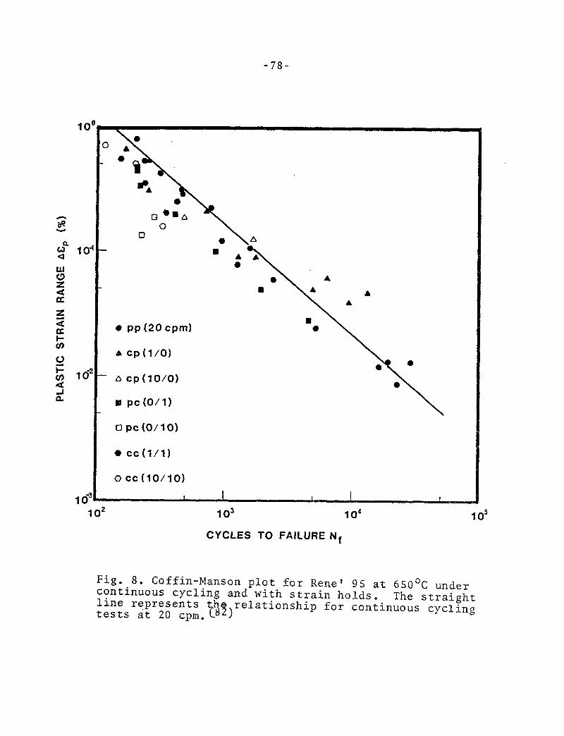
-78-
0 Cl
0 PP (20 cpm)
- a cp(lO/O) 0
0 pc(O/l) \
opc(0/10)
0 cc(l/l)
0 cc(10/10)
I I I I
lo2 lo3 lo4 lo5
CYCLES TO FAILURE Nf
Fig. 8. Coffin-Manson plot for Rene' 95 at 650°C under continuous cycling and with strain holds. line represents th
8%
The straight
tests at 20 cpm.C relationship for continuous cycling

60 80 100 120 140 160 180 200
-79-
A
A A A
0
cl
l s
/
0 pp (20 cd
0 A cp (l/O)
a cp (10/O)
8 pc(O/l)
0 pc(O/lO)
l cc(l/l)
I 0 cc(10~10)
MAXIMUM TENSILE STRESS CJ,,, (ksi)
Fig. 9. The dependence of maximum tensile stress on plastic strain range for different cycle types. Note the shift in maximum tensile stress developed during hold time compared to continuous cycling (represented by the straight line).(82j

-8O-
2011
( b)
Fig. 10. Typical crack initiation region fdr specimens tested at high strain ranges under continuous cycling. In (a) thcrc is a transgranular initiation followed by a mixed mode of propagation. In (b) crack origin is shown at higher magnification with faint striations and bi(. car-bides (arrows) visible on the fracture surface.

-81-
Fig. 11. Crack initiation region where the crack probably had initiated intergranularly and further propagated mainly by transgranular mode. Note that the striation like feature are quite brittle in nature.
Fig. 12. SEM micrograph of a longitudinal section showing a crack which had initiated transgranularly. Note the crack changed direction upon travelling across a single warm worked grain or crossing the necklace regions.

-82-
Fig. 13. Typical facets present on the fracture surface in the later stage of crack propagation.
Fig. 14. Typical crack initiation at a surface MC carbide (arrow) which had fallen off during testing.
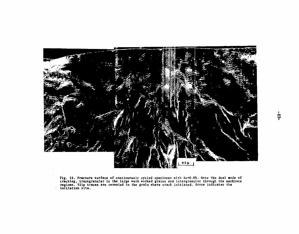
Fig. 15. Fracture surface of continuously cycled specimens with As=O.9#. Note the dual mode of cracking, transgranular in the large warm worked grains and intergranular through the necklace regions. Slip traces are revealed in the grain where crack initiated. Arrow indicates the initiation site.

-- -. -. “s., ” I I, I I
-&I-
b)
Fig. 16. SEM micrograph showing cracking of MC carbides on the gage surface of specimens. In (a) two surface MC carbides had ruptured during testing while(b) shows further propagation into the matrix. The longitudinal marks are due to the finish machining operation.
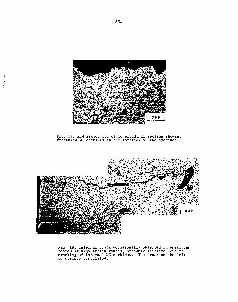
-85-
Fig. 17. SEbl micrograph of longitudinal section showing fractured MC carbides in the interior of the specimen.
Fig. 18. Internal crack occasionally observed in specimens tested at high strain ranges, probably initiated due to cracking of internal MC carbides. The crack on the lcrt is surface associated.

-86-
Fig. 19. SEM micrograph of gage surface showing slip offsets in the crack propagation region.
Fig. 20. The edge of the fracture surface away from the crack origin parallel to the slip offsets on the gage surface.

-87-
r 1, tracct 217 1
Fig. 21. Deformed microstructure of Rene' 95 in a single warm worked grain showing microtwins (trace T) and slip bands (trace S).
Fig. 22. Planar slip in a necklace grain of Rene' 95.

Fig. 23. Intergranular crack initiation and early propagation in specimens tested at Aet=1.4% under tensile hold (a), compressive hold (b) and balanced hold(c).

-89-
(b)
Fig. 24. Mixed mode of cracking in specimens tested under hold times showing fracture features facets (a) and striation like feature (b) in the waim worked grains.

-9o-
Fig. 25. Crack initiation in the necklace region for hold time tests.
Fig. 26. A crack initiated transgranularly and propagated intergranularly before meeting a warm worked grain.

Fig. 27. Dual mode of cracking in specimen tested under tensile hold with,Ac;0.9#. This is typical for hold time tests at low strain ranges. Arrow indicates initiation site.

180
- 160 .- 2 Y
5 140 bE
a cp(lO/O)
I pc(O/l)
cl pc(O/lO)
0 cc(l/l)
0 cc(10/10)
60 10’ lo3 10’
CYCLES TO FAILURE Nf
Fig. 28. Dependence of life on maximum tensile stress for all cycle types. Al+ the data seerngis, three tensl.le hold times.
fall into three lines corresponding to

-93-
Fig. 29. Microstructure of NARloy Z showing intermetallic compound Cu-10 Ag-22.5 Zr and annealing twins.

-94-
(a)
Ag [rings]
(b)
Fig. 30. (a) TEM micrograph showing initial structure of NARloy Z with larger precipitates Ag and relatively small precipitates Cu20. (b) Diffraction pattern under (111). The former give rise to rings while the latter, superlattice spots.
t I
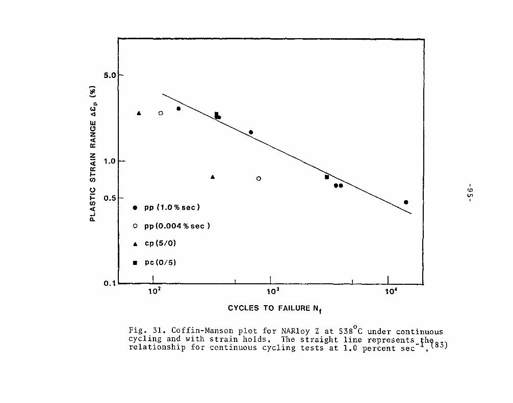
5.C
1.0
0.5
0.1
0 pp (0.004 % set 1
A cp (5/O)
l pc(O/5)
1 I I I I 10Z 103 10’
CYCLES TO FAILURE Nf
Fig. 31. Coffin-Manson plot for NARloy Z at 538’C under continuous cycling and with strain holds. The straight line represents relationship for continuous cycling tests at 1.0 percent set -1’783) D

-96-
(b)
Fig. 32. Typicaglfracture feature for specimens tested at 1.0 percent set . (a) shows transition of cracking from intergranular to transgranular mode. (b) shows striations in the region of transgranular crack propagation.

-97-
Figz133. Gage surface of specimens tested at 1.0 percent set showing grain boundary decohesion.
f
J
c b 1
(a) Fig. 34. (a) Longitudinal section of specimens tested at 1.0 percent set showing surface cracks ceased growing right after initiation.

-98-
(b)
Fig. 34. (Continued) (b) shows a crack which had grown tuo or three grains in depth. (c) shows a crack grew like the main crack, transgranularly into the matrix.
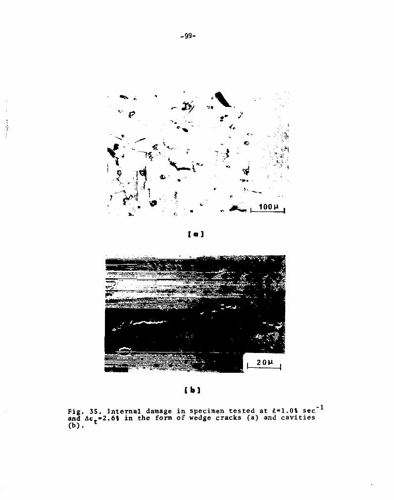
-990
f
Fig. 35. Internal damage in specimen tested at t=l.O% set-' and Act=2.6% in the form of wedge cracks (a) and cavities
(b) l
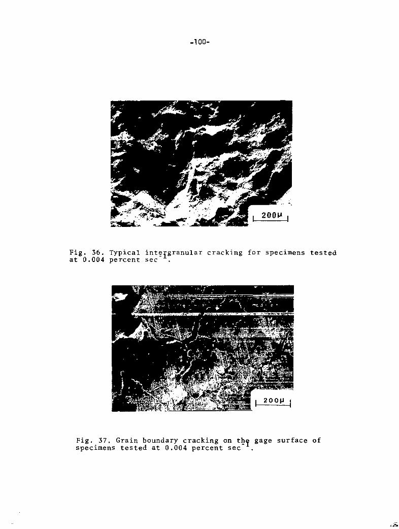
-1 oo-
, 2OOP ,
Fig. 36. Typical intergranular cracking for specimens tested at 0.004 percent set .
Fig. 37. Grain boundary cracking on thf gage surface of specimens tested at 0.004 percent set .

-lOl-
Fi 8. 38. Typical surface intfrgranular crack for specime te sted at 0.004 percent set .
ns
Fig. 39. Typical lfternal damage for specimens tested 0.004 percent set .
at

-102-
Fig. 40. Transition of cracking from intergranular to trans- granular mode in specimens tested under compressive hold.
-
Fig. 41. Severe preferential grain boundary oxidation in specimens tested under compressive hold.

-103-
Fig. 42. Occurrence of recrystallization in the gage section of specimen tested under compressive at Act= 0.9%.
Fig. 43. Intergranular fracture on specimens tested under tensile hold.

-104-
c-2 . m ‘- .@ ,: ., . ! . . . ‘ ‘95 . 4.’ L . .
:
Fig. 44. Internal cracks in specimen tested under tensile hold at AE~= 2.6%.
Fig. 45. Linkage of surface and internal cracks in specimen tested under tensile hold at Act=0.9%.

0 PP A Slow-f;
I3 fast-sic
CYCLES TO FAILURE Nf
Fig, 46. Coffin-Manson plot for NARloy Z under continuous cycling at medium strain rate, slow-fast and fast-slow cycling (re uisfj ented by open symbols). Data from Fig. 31 are superimposed also.

-106-
Ibl
Fig. 47. TEM micrograph showing deformed microstructurf of NARloy Z tested under continuous at 0.004 percent set . (a) shows a grain with random distribution of dislocations and most of them-were pinned by Ag precipitates. In &I, in the same specimen subgrains had formed.

1. Report No. NASA CR-3543
4. Title and Subtitle
HIGH TEMPERATURE LOW CYCLE FATIGUE MECHANISMS FOR A NICKEL-BASE AND A COPPER-BASE ALLOY
7. Author(s)
Chin-I Shih
9. Performing Organization Name and Address University of Cincinnati
8. Performing Organization Report No.
None
10. Work Unit No.
Department of Materials Science and Metallurgical Engineering 11. Contract or Grant No.
Cincinnati, Ohio NSG-3263
13. Type of Report and Period Covered 12. Sponsoring Agency Name and Address
National Aeronautics and Space Administration Washington, D. C. 20546
Contractor Report
14. Sponsoring Agency Code 505-33 -22
15. Supplementary Notes
Final report. Project Manager, Robert C. Bill, Structures and Mechanical Technologies Division, NASA Lewis Research Center, Cleveland, Ohio 44135. Report was submitted as a thesis in Partial fulfillment of the requirements for the degree Master of Science to the University of Cincinnati, Cincinnati, Ohio.
16. Abstract
Damage mechanisms were studied in nickel-base superalloy Rene* 95 and copper-base alloy NARloy Z, using optical, scanning and transmission in microscopy. Continuous cycling and strain hold time tests were performed at 6500C for Rene’ 95 and at 538OC for NARloy Z under AGARD SRP program Results showed that the two materials, having quite different microstructures and tensile properties, exhibited contrasting LC F behavior. In necklace Rene’ 95, crack initiation was mainly associated with cracking of surface MC carbides, except for hold time tests at higher strain ranges where initiation was associated more with a grain boundary mechanism A mixed mode of propagation with a faceted fracture mor- phology was typical for all cycle characters. Due to the plastic strain range being much less than the elastic one, pronounced opposite shift of mean stress occurred during hold time, which accounted quan- titatively for the observed fatigue behavior. Compressive hold appeared more detrimental than tensile hold mainly due to its higher maximum tensile stress. The dependence of life on maximum tensile stress CCLII be demonstrated by the data falling onto three lines corresponding to the three tensile hold times, in the life against maximum tensile stress plot. Consequently, the fatigue life models that hypo- thesize a deleterious creep-fatigue interaction tend to underpredict lives of tensile hold and overpredict in the case of compressive hold. In NARloy Z, crack initiation was always at the grain boundaries. The mode of crack propagation depended on the cycle character. It was transgranular mode for con- tinous cyclong at high strain rate and for compressive hold, Intergranular propagation under continuous cycling at low strain rate was due to environmental effect and it was due to both creep and environmental effects for tensile hold tests. The life, therefore, decreased with decreasing strain rate and with tensile holds. In terms of damage mode, different life prediction laws may be applicable to different cycle characters, e. g., Coffin-Manson law to continuous hold, Coffin’s frequency modified model to continuous cycling at low strain rate and SRP model to tensile hold.
17. Key Words (Suggested by Author(s) ) Fatigue High temperature
Life prediction
Creep Creep-f atiaue Microstructure
18. Distribution Statement
Unclassified - unlimited STAR Category 26
19. Security Classif. (of this report)
Unclassified 20. Security Classif. (of this page) 21. No. of Pages
Unclassified 110
*For sale by the National Technical Information Service, Springfield, Virginia 22161
22. Price*
A06
NASA-Langley, 1982