The Fracture Morphology of Nickel-Base Superalloys … · NASA Technical Memorandum 81740 The...
25
NASA Technical Memorandum 81740 The Fracture Morphology of Nickel-Base Superalloys Tested in .... Fatigue and Creep-Fatigue at 650 ° C !, (NASA-TM-817_O) THE FRACTURE MORPHOLOGY OF NICKEL-BASE SUPERALLO¥S TESTED IN FATIGUE AND CIIEEP-FATIGUE AT 650 C (NASA} 26 p HC AO3/MF A01 CSCL 11F N81-23244 Unclas G3/26 42395 John Gayda and Robert V. Miner Lewis Research Center Cleveland, Ohio April 1981 https://ntrs.nasa.gov/search.jsp?R=19810014711 2018-07-17T01:42:37+00:00Z
Transcript of The Fracture Morphology of Nickel-Base Superalloys … · NASA Technical Memorandum 81740 The...
NASA Technical Memorandum 81740
The Fracture Morphology of
Nickel-Base Superalloys Tested in ....
Fatigue and Creep-Fatigue at 650 ° C
!,
(NASA-TM-817_O) THE FRACTURE MORPHOLOGY OF
NICKEL-BASE SUPERALLO¥S TESTED IN FATIGUE
AND CIIEEP-FATIGUE AT 650 C (NASA} 26 p
HC AO3/MF A01 CSCL 11F
N81-23244
Unclas
G3/26 42395
John Gayda and Robert V. Miner
Lewis Research Center
Cleveland, Ohio
April 1981
https://ntrs.nasa.gov/search.jsp?R=19810014711 2018-07-17T01:42:37+00:00Z
!
THE FRACTURE MORPHOLOGY OF NICKEL-BASE SUPEPALLOYS TESTED
IN FATIGUE AND CREEP-FATIGUE AT 650" C
by John Gayaa and Robert V. Miner
National Aeronautics ana Space Administration
Lewis Research Center
Cleveland, Ohio 44135
SUMFtARY
The fracture surfaces of compact tension specimens from seven nickel-
base superalloys fatigue tested at 650: C were studiea by scanning electronmicroscopy and optical metallography to determine the nature and morphology
of the crack surface in the region of stable growth. Crack propagation
testing was performed as part of an earlier study at 650" C in air using a0.33 Hz fatigue cycle and a creep-fatigue cycle incorporating a 900 second
dwell at maximum load. The alloys studied included HIP Astroloy, Waspaloy,
HIP plus forged Astroloy, MERL 7b, IN 100, Rene 95, and NASA lIB-7. Each
alloy is ganm_a prime strengthened, but composition, microstructure, and
strength levels vary from alloy to alloy.In fatigue, alloys with a grain size greater than 20 _m, HIP Astroloy,
Waspaloy, and MERL 76, exhibited transgranular fracture. MERL 76 also Uis-
played r_umerous fracture sites which were associated with boundaries of
prior powder particles. This behavior was especially noticeable at higher
stress levels. The two high strength, fine grain alloys, IN 100 and NASA
lIB-7, exhibited intergranular fracture. Rene 95 and HIP plus forged
Astroloy, which possess a necklace structure, displayed a mixed failure mode
that was transgranular in the coarse grains and intergranular in the fine
grains. Fatigue crack growth rates were lowest for the low strength, coarsegrain alloys which failed in a transgranular fashion.
Under creep-fatigue conditions, fracture was found to be pred_linantly
intergranular in all seven alloys; however, two of the alloys displayed
additional features. Waspaloy also fractured at twin bounJaries on occa-
sion, while numerous prior particle fracture sites were again observed in
MkRL 76. As in fatigue, the crack growth rate of the low strength, coarse
grain alloys were lowest, but tne crack growth rate of all alloys increased
sigr_ificantly under creep-f_tigue conditions.
INT_UDULT ION
Fatigue is Known to be a limiting factor affecting the useful life of
aircraft turbine engine aisks. Both initiation and propagation of fatigue
cracks are important aspects of the overall problems. Furthermore, in the
rim of high performance turbine disks where temperatures can approach
650 ° C, time dependent effects arising from creep.fatigue-environment inter-
actions I-2 ma_ further complicate the problem. NASA has recently spon-
sored studies _-6 to examine the fatigue and creep-fatigue behavior- of
seven turbine uisk alloys, HIP Astroloy, Waspaloy, HIP-plus-forged (H+F)
Astroloy, MERL 7b, II_ i00, Hone 95, and N_SA lIB-7, all ot which are ganm_a-
prime (_') stFen_tnened, nicKel-base superalloys. These alloys incluGe both
a cast and _,rought alloy, Waspaloy, as well as several of the latest genera-tion powder |,_etallurgyalloys representing a wide range of strength levels.

Crack propagation behavior was studied with compact tension specimens at atemperature of 650" C, which may be representative of critical rim locations
in high performance turbine disks. To study time dependent effects, a fast
fatigue cycle, 0.33 Hz, and a creep-fatigue cycle, incorporating a 900 sec--ond tensile dwell at maximum load, were evaluated.
The results of these studies have shown the higher strength alloys, IN
100, Ren_ 95, and NASA lIB-7, possess longer total fatigue |ives below one
percent strain range, compared with the low strength alloys, HIP Astroloyand Waspaloy, due to an increased resistance to crack initiation. Crack
propagation rates are, however, much higher for the high strength alloysparticularly in creep-fatigue.
In the present investigation, crack propagation test specimens from the
previous studies 4-6 were examined in detail in an attempt to correlate
failure mode, crack growtn rates, and metallurgical structure. The crack
growth results of the earlier studies n-6 are summarized in this paper and
are correlated with local fracture morphology for a11 seven alloys. In
addition, the fracLure morphology is related to cycle type and the stressintensity range.
IV_TERIALS AND PROCEDURES
Materia ]s
All materials used in this study were obtained from turbine disk pre-
forms with the exception of NASA lIB-7, which was procureU as plate. The
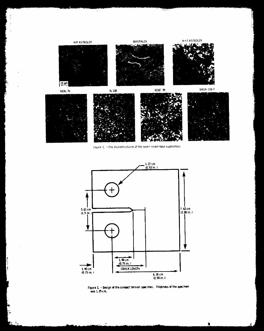
microstructures of the seven nickel-base superalloys studied herein are pre-sented in figure 1. The chemical composition, mechanical properties, and
heat treatments can be found in tables I and II. These a|loys are all y'strengthened, but their y' content, morphology, and distribution vary wide-
ly, as shown in table Ill. A more detailed description of each alloy ispresented below.
HIP Astroloy was produced by hot isostatical]y pressing low carbon
Astroloy powUer for 3 hours at 1190 ° C and 104 MPa. The al]oy is not sub-
sequently forged and the resulting structure, after heat treatment, contains
44 percent _' which was determined by electrolytic extraction proce-
dures. I In this alloy, about half of the _' is present as cube shaped
particles 0.1 to 1.0 _m in size. The remainder is uniformly distributed
throughout as finer particles about 0.03 um. The grain size is nearly unio-form in this material at 50 to 70 _m.
Waspaloy, produced by _orging a cast billet, contains approximately 2U
percent y', which occurs as a uniform distribution of spherical particlesabout 0.03 um in diameter and an occassiona| partic]e about 0.3 um in diame-
ter. The grain size is predominantly 40 to 150 _m. Grain boundary carbides
of the M23 C6 and MC type 7 clear]y delineate the grains, as seen infigure 1.
H+F Astroloy was forged fron_ a HIP processed powder billet. A necklace
structure is produced by the forging operation, in which large grains, 50 to
100 _m, are surrounded by fine, recrystallized grains, 15 _m and less. The
aI]oy contains 42 percent y', which occurs as large blocky particles 0.5 to
3.U _m concentrated in the fine, recrystallized grains and smaller, more
uniform particles about 1.O um in t_e larger grains. In addition, fine _'
particles 0.3 and 0.04 _m are uniformly distributed throughout.
MERL 76, another powder metallurgy alloy, was hot isostatically pressedat 1182" C for 3 hours at 103 MPa, but was not forged. After heat treat-

ment, the alloy contains bO percent y' of which about half is present as
large blocky particles 0.5 to 5.0 _m in size. The remaining y' is composedof smaller particles 0.2 and 0.03 um. In this alloy, the grain size is
nearly uniform at 15 to 20 _m. A dendritic solidification structure is
apparent in many grains.IN 100 was produced by the Gatorizing TM process, in which powder is
hot compacted, extruded, and then isothermally forged at a low strain ratewhere material behavior is superplastic. After heat treatment, the alloy
has a _' content of 62 percent, of which about half is present as large
blocky particles 0.5 to 5.0 _m in size, while the balance is uniformly dis-tributed as finer particles 0.05 to O.15 _m. The grain size is quite uni-
form at 4 to 6 um.
Rent 95 was forged from a HIP processed powder billet. It contains 50
percent y' after neat treatment. This alloy has a necklace structure inwhich large grains, 50 to 70 _m, are surrounded by fine, recrystallized
arains, 15 um and less. The _' is present as large blocky particles 0.5 toum concentrated in the necklace grains and smaller particles 0.5 to I _m,
which are found in the larger grains. Fine _' particles 0.03 to 0.06 _m
are also uniformly distributed throughout.
The last alloy, NASA lIB-7, was _hade b_ hot isostatically pressing
argon-atomized powde_ for two hours at 1215 C ana 100 MPa,ofollowea by anintermediate heat t_eatment, and then cross-rolling at 1065 C to a 55 per-
cent reduction in thickness. This alloy, after a final heat treatment, con-
tains 59 percent y'. About half of the y' is composed of large blocky
particles 0.5 to 5.0 um in size, while the balance is urifomly distributed
as smaller particles 0.03 to U.U0 um. The grain size is 4 to bum.
Crack Growth Testing
Crack propagation data were obtained on the seven superalloys using
compact tensi_n specimens 4-0 illustrated in figure 2. Testing was done in
air at 050 ° L using a tervohydraulic, closed-loop, load-controlled test
machine operated in tension at a frequency of 0.53 Hz and a load ratio(nlinimum load/maximum load) of O.U5. A simple triangular waveform was usedfor fatigue loading while a 900 secon_ dwell at maximum load was added tothe simple fatigue wavefarm for creep-fatigue loading. All specimens wereprecrackad at room temperature in accoruance witll ASIN E-399. Both fatigueand creep-fatigue testing was continued until total specimen failureoccurred. During the test, crack growth _as checked at regular intervalswith a traveling microscope, after cooling the specimen. From this informa-tion, discrete values of aa/AN (crack length/cycle) versus AK (stressintensity range) were plotted, through which a smooth curve was constructedbased on the hyperbolic sine model. 8 The basic equation describing thismodel is presented below:
log(aaldn) = CI sinh(C2(log(aK)) + C3) + C4
The coefficients, CI through Ca, are determined by regression analysisof the raw aata.
Fractography
The fracture surfaces of the compact tensiof_ specimens were examined
_vith a scanning electron microscope. All fractographs were taken along the
centerline of the specimen, starting in the precrack region and terminatingin the fast fracture region. Further, the location of each fractograph wasaccurately recorded with respect to the precrack interface so the cracklength and stress intensity range could be computed and correlated with
local fracture morphology.Optical micrographs were also used to characterize fracture morphol-
ogy. Sections perpendicular to the direction of crack propagation were cut
from the compact tension specimens, mounted, polished, and some were etched
in a 10 percent solution of H202 (30 percent) in concentrated HCl acid.
These specimens were examined in the etched and unetched condition with a
metallurgical microscope and the scanning electron microscope. The positionof each section with respect to the precrack interface was noted so the
crack length and stress intensity range could be calculated and correlated
with local fracture morphology.
RESULTS AND DISCUSSION
Crack Growth Rates
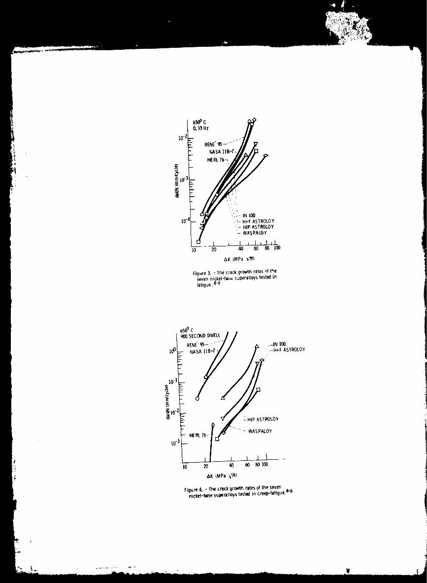
Results of the crack propagation tests, 3-5 in which growth rates are
plotted as a function of the stress intensity range, are reproduced in fig-
ure 3 for Fatigue tests and in figure 4 for the creep-fatigue tests. Eachof these curves are an average of at least three trials although not all of
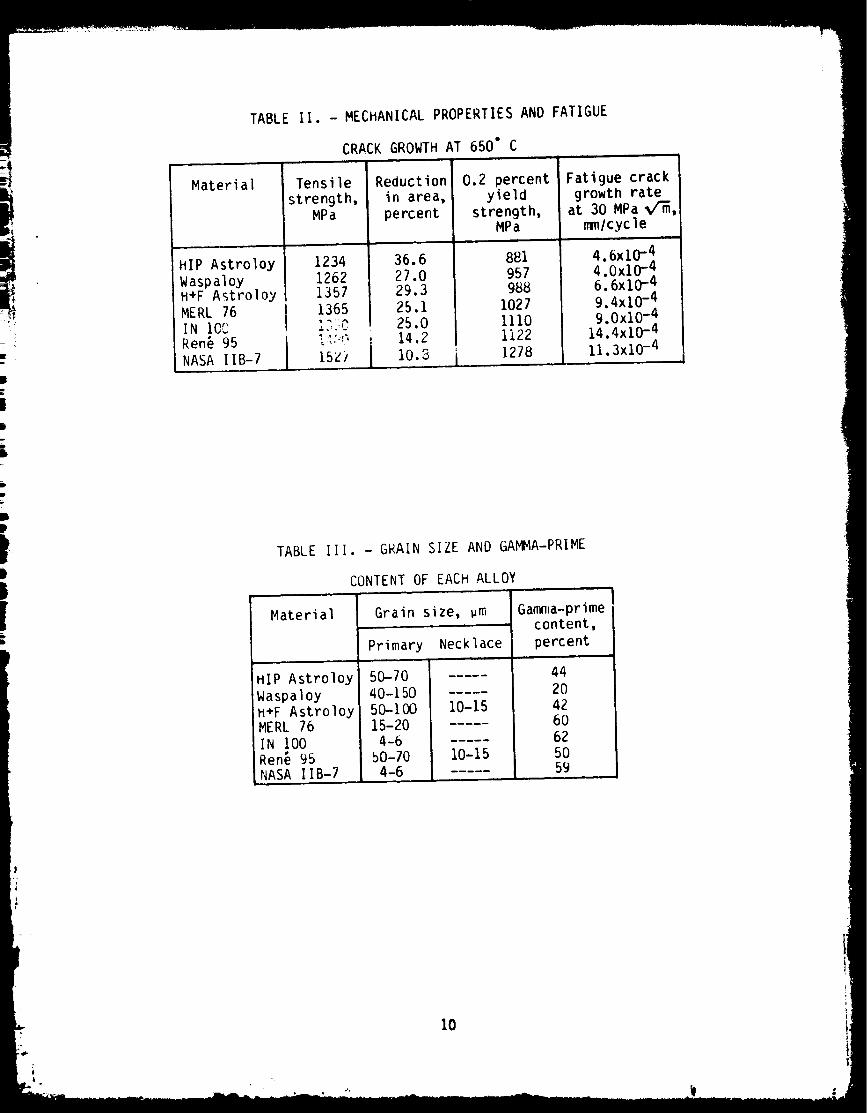
the individual tests cover the range shown.Those alloys with lower yield strengths at 650 ° C generally exhibit
lower crack propagation rates in fatigue, as seen in table If. However, an
exact ranking of crack growth rates with strength did not exist. The most
notable exception to the ranking of the alloys was NASA lIB-7, the strongest
alloy, and Rene 95. Over the range of the data, Rene 95 displayed the high-
est crack growth rate of any alloy tested. The ranking for HIP Astroloy and
Waspaloy was also inverted relative to yield strength above 25 MPa_. The
crack propagation data shown in figure 3 tends to converge at low values ofthe stress intensity range, suggesting these alloys have a similar threshold
stress intensity under fatigue loading.
In all instances, the crack growth rates for the creep-fatigue condi-tions increased at least one order of magnitude over the fatigue tests, with
the stronger alloys exhibiting a much more pronounced increase. In compari-
son to the fatigue crack propagation data, the crack growth rates for the
creep-fatigue test exhibit a greater spread between alloys. Once again, the
lower strength alloys tend to have lower crack propagation rates; however,an exact ranking between crack propagation and strength is lacking. Theorder of NASA lIB-7 and Ren_ 95 is again inverted relative to yield strength
with Rene 95 having the highest crack growth rate over the range of the data.
Fracture Morphology
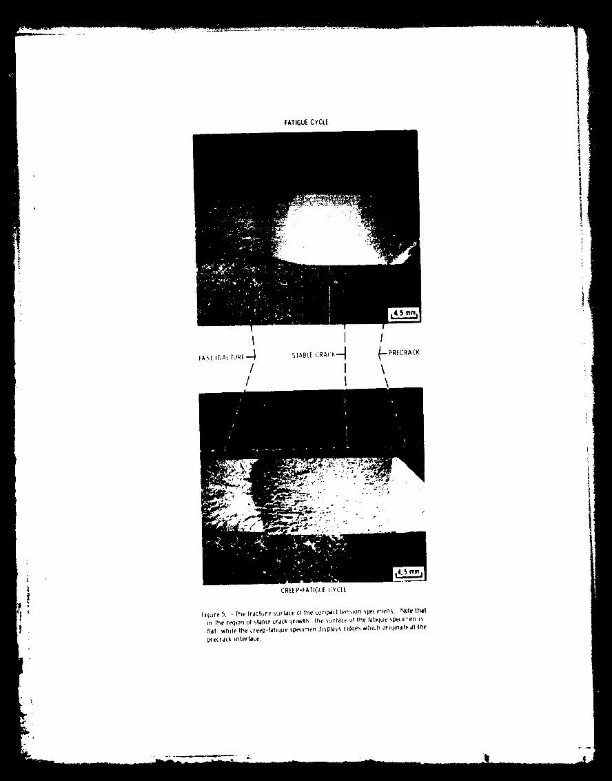
At low magnification, the fracture surface morphology of all specimens
can be divided into three regions which correspond to room temperature pre-
cracking, stable crack growth at temperature, and final fast fracture.
These three regions are clearly seen in figure 5 for the fatigue anG creep-
fatigue test cycle. In most cases, the stable crack growth region of the
fatigue specimens was flat. However, on the creep-fatigue specimens paral-
lel ridges originating at the precrack interface ran down the length of thefracture surface. The severity and depth of these ridges increased with
increasing crack length as seen in figure 5.
4

Although the fracture morpllology of the precrack region was different
from that in the fast fracture region, these regions varied little amongalloys or test cycles. Precracking at room temperature produced trans-
granular fracture for all alloys, while the fast fracture region exhibited a
dimpled appearance characteristic of tensile failures 9 with occasional
cleavage-like facets.
Fatigue. - Under fatigue conditions, the fracture n_de associated with
stable crack growth varied from alloy to alloy. Waspaloy and HIP Astroloy,
with grain sizes greater than 40 um, exhibited a transgranular fracture mode
as seen in figure 6. These two alloys also displayed the lowest crack
growth rates. The two fine grain alloys, IN 100 and NASA lIB-7, exhibited
an intergranular fracture mode as seen in figure 7. Their crack growth
rates were greater than those of Waspaloy or HIP Astroloy.Alloys which possessed the necklace structure, H+F Astroloy and Ren_
95, exhibited a mixed fracture mode when tested in fatigue at 0.33 Hz. The
fine recrystallized grains failed along grain boundaries, while the larger
grains showed a transgranular failure mode as seen in figure 8. H+F
Astroloy was more resistant to crack propagation than the high strength,
fine grain alloys, but not as resistant as the low strength, coarse grainmaterial. Ren_ 95, as previously stated, exhibited the highest crack growth
rate, but it was neither the strongest a11oy nor aid it possess the finest
grain size. Ranking crack growth rate with grain size is somewhat ambiguous
for these a11oys since cracking was both transgranular in the coarse grains
and intergranular in the fine, recrystallizea necklace grains. Therefore, a
rankina of crack growth rate with either grain size in these alloys could bemisleading.
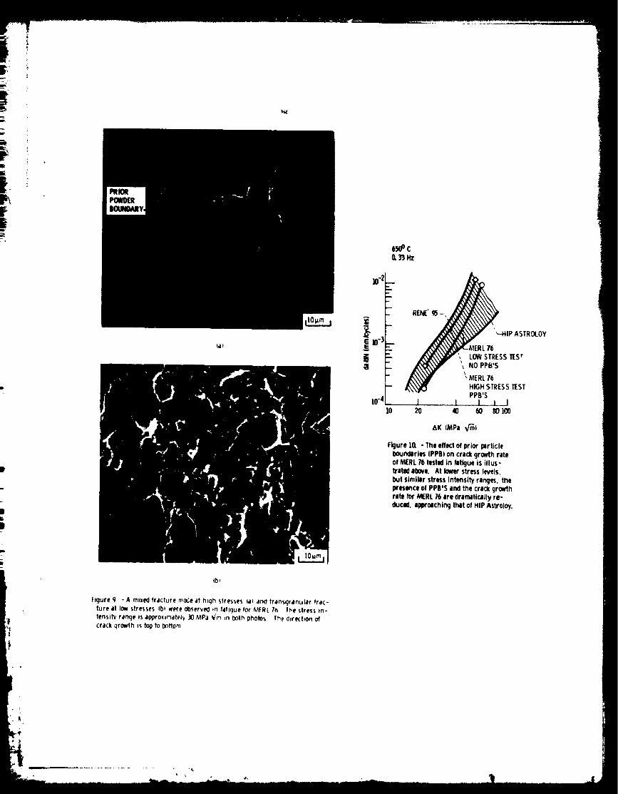
Fatigue failure in FIERL 7b, with a grain size of 15 to 2U _m, was basi-
cally transgranular. However, occasional fracture along prior particle
boundaries (VPB) was observed as seen in figure 9. The frequency of the PPB
fracture sites increased as the crack grew and stress level increased, being
most severe in the fast fracture region. Fracture along the PPB's wasbelieved to have been caused by a thin hafnium rich oxide layer found on the
surface of the larger powder particles. These particles were found to be
present throughout the powder blend used to fabricate the disk from which
the specimens were cut.10 Oxidlzed powder particles were not found in
other blends of MERL 76. The crack growth rate of the specimens exhibiting
PPB fracture sites was intermediate compared to the other alloys. A sub-
sequent crack growth test run at a lower stress level, but equivalent stressintensity range, virtually eliminated the PPB fracture mode in the stable
crack growth region. PPB fracture sites were still observed near and in the
fast fracture zone where stress levels are highest. The crack growth rateof this specimen was dramatically decreased (fig. 10) and approached that of
HIP Astroloy which also exhibited transgranular fracture. This result isbelieved to reflect the behavior of MERL 76 when high quality powder is used.
At lower stress intensities, under fatigue conditions, fracture detail
was more closely associated with microstructural features, especially grain
size. This behavior was most readily seen in H+F Astroloy (fig. 11(a))
where failure was intergranular in the fine grains and transgranular in the
coarse gr_ins. As the crack grew, two prominent changes were observed.
First, the transgranular fracture surfaces developed deep secondary cracks
which were approximately aligned with the n_ain crack front. Such cracks
have been observed before and are associated with slip band cracking andcleavage 11. Second, the fine grain areas, which fractured along grain
boundaries at lower stress intensity rar_ges, begin to show some regions
i
which appear to have failed in a transgranular manner as seen in figure
11(b). These results ar@ consistent with the observations of others at high
stress intensity ranges, _( and have been attT)buted to the development of
a large plastic zone ahead of the crack tip. _In summary, fatigue crack propagation was transgranular when the grain
size exceeded 20 pm. Of all the metallurgical variables, grain size ap-
peared to have the greatest effect on fracture morphology particularly atlower stress intensity ranges. While Y' size and distribution are known toaffect the fracture mode in fatigue, 11-I2 no definite relationship was
evident in the present study. This result is not surprising since the pur-
pose of the present investigation was a comparison of seven commerciallyheat treated turbine disk alloys, while earlier studies on Ren_ 95" and
Astroloy 12 varied y' size and distribution in a controlled fashion.
Presently, research is underway at NASA to investigate the combined effectsof grain size and y' morphology on crack propagation in low carbon Astroloy
at temperatures of interest for turbine disk applications.
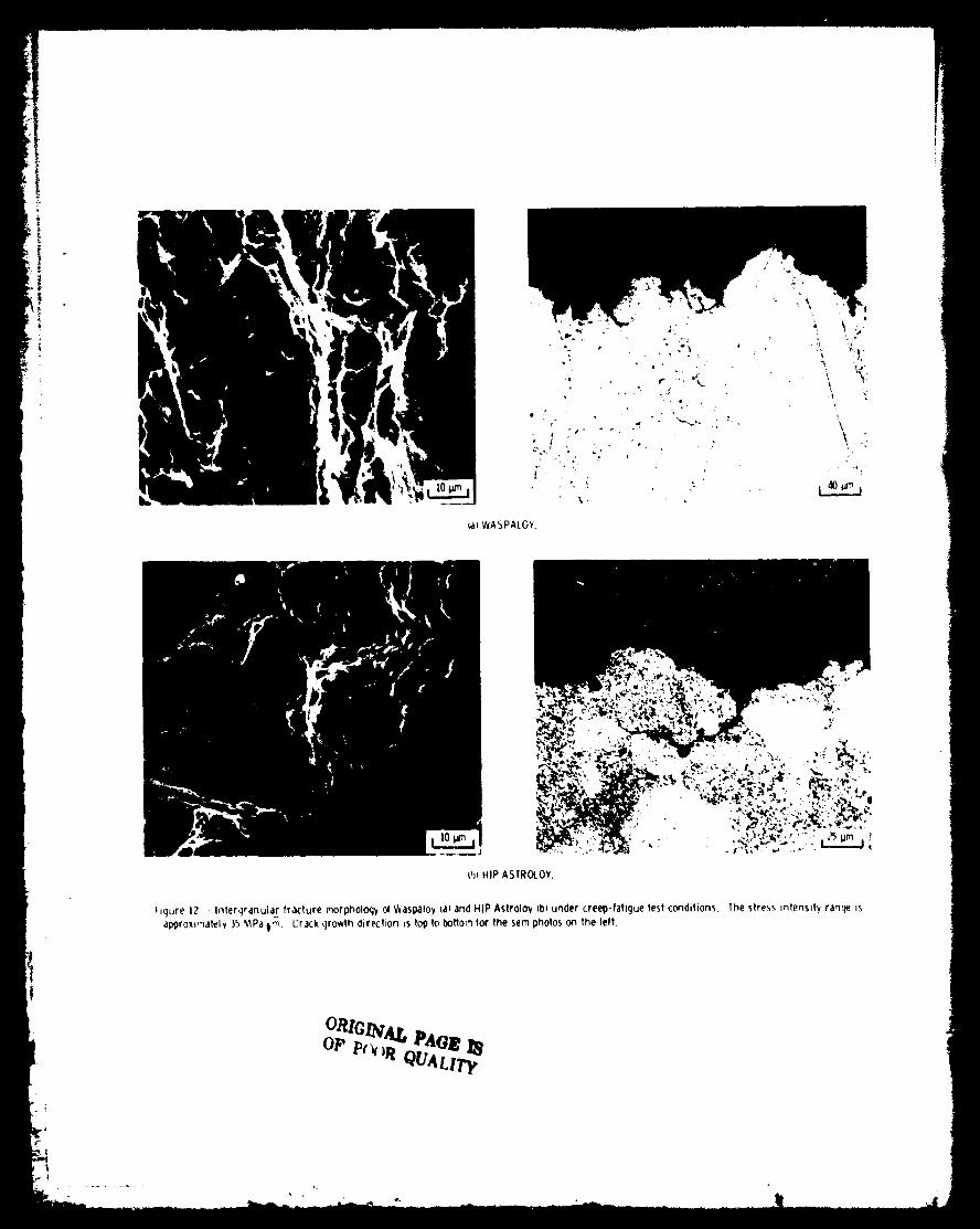
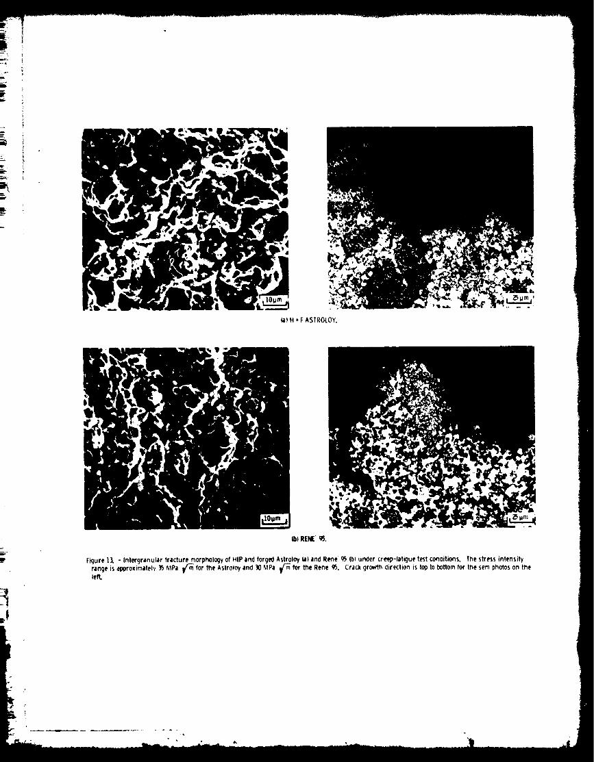
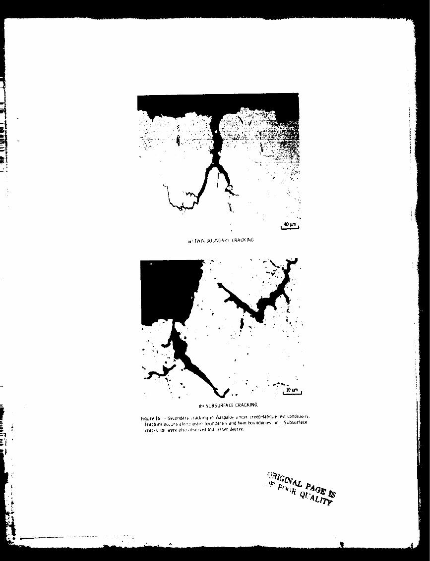
_. - Under creep-fatigue conditions, the fracture n_rphol-ogy of all alloys was predominantly intergranular, as seen in figures 12 to16. MERL 76 also exhibited fracture sites associated with prior particle
boundaries (fig. 15) while Waspaloy was found to crack along twin boundaries
on occasion (fig. 16). In both cases fracture was predominantly inter-
granular as previously stated. Intergranular secondary cracking was present
in all alloys and very little cleavage or slip band cracking was observed.Further, there was little change in fracture morphology at higher values of
the stress intensity range. Fracture remained predominantly intergranular.
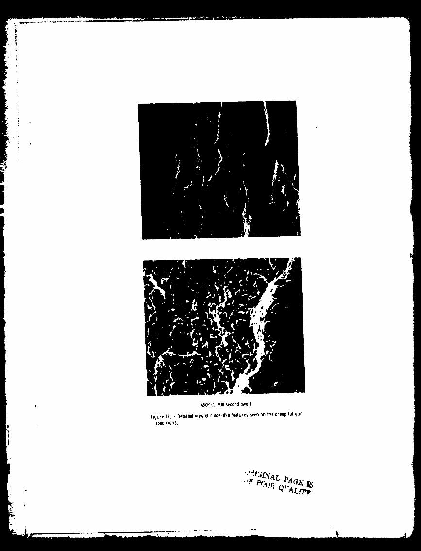
The gross ridges shown earlier in figure 5 become more severe as the crack
grows. A more detailed view of these ridges (fig. 17) reveals an erratic
fracture path with many deep secondary cracks. This behavior differs sharp-
ly from the fatigue tests in which the fracture surface is relatively flatand secondary cracks are shallow. While the ridges on the creep-fatigue
specimens were associated with cracking along grain boundaries, spacing
between adjacent ridges was much larger than the grain size and could not be
linked with any other structural feature.Examination of sections cut perpendicular to the fracture surface did
not reveal grain boundary cavities at magnifications up to 30OOX. In sev-eral instances, oxidized subsurface cracks were observed, as seen in fig-
ure 16. However, a majority of the cracks were linked with and appear to
have originated at the primary fracture surface. These observations suggestan environmental interaction has accelerated crack growth along grain
boundaries.
Under creep-fatigue cycling as under fatigue cycling, the crack growth
rates of the high strength, fine grain alloys, IN 100 and NASA lIB-7, were
higher than the low strength, coarse grain alloys, Waspaloy and HIPAstroloy. The alloys with a necklace structure H+F Astroloy and Ren_ 95,
exhibit crack growth rates which were greater than the low strength, coarse
grain materials. Nowever, H+F Astroloy was h_re resistant to crack growththan the high strength, fine grain alloys, while Ren_ 95 possessed the high-
est crack growth rate of all the alloys. Taking necklace grain size as the
important parameter in creep-fatigue, the ranking between crack growth rateand grain size holds for H+F Astroloy but does not hold for Ren_ 95. Thesame can be said of the ranking between crack growth rate and strength. In
either case, Rene 95 does not follow the general trend. The presence of PPBfracture sites seems to have affected the crack growth rate of MERL 7b in
that stable crack growth conoitions could not be produced above 25 MPa_/'m'.
Extrapolation of the data does suggest an intermediate crack growth rate
which is consistent with the ranking of crack growth rate with strength and
grain size.
In summary, creep-fatigue crack growth occurred by an intergranular
fracture mechanism regardless of grain size. However, crack growth rates
were, in general, lowest for the low strength, coarse grain alloys.
CONCLUSIONS
Fatigue crack propagation at 650" C for seven nickel-base alloys was
fuund to be dependent on cycle type, stress intensity, and microstructure asfollows:
(1) Under fatigue loading, the low strength, coarse grain alloys were
more resistant to crack propagation than the high strength, fine grain
alloys.
(2) Fracture morphology in fatigue was transgranular for alloys with a
grain size greater than dbout 20 pm and intergranular for alloys with a
finer grain size. For materials with a necklace structure, fracture was
intergranular in the fine, recrystallized grains and transgranular in the
coarse gr_ins.(3) Under creep-fatigue loading, the crack growth rates of all alloys
increased substantially. As in fatigue, the low strength, coarse grain
alloys were more resistant to crack propagation than the high strength, fine
grain alloys. Fracture was predominantly intergranular in all instances.
(4) The behavior of MERL 76 is basically similar to the other coarse
grain alloys, but contamination of the larger powder particles produced an
additional failure mechanism along the boundaries of these particles. The
presence of the prior particle boundaries (PPB's) is thought to have ad-
versely affected the crack growth rates especially at elevated stress levels.
REFERENCES
I. Runkle, J. C.; and Pelloux, R. M.: Micromechanisms of Low-Cycle Fatigue
in Nickel-Based Superalloys at Elevated Temperatures. Fatigue Mech-
anisms, J. T. Fong, ed., ASTM STP-675, American Society for Testing anaMaterials, 1979, pp. 501-527.
2. Sadananda, K.; and Shahinian, P.: Crack Growth Under Creep and Fatigue
Conditions. Creep-Fatigue-Environment Interactions, TMS-AIME Confer-ence Proceedings, Fall Meeting, R, M. Pelloux and N. S. Stoloff, eds.,
American Institute of Mining, Metallurgical and Petroleum Engineers,
1979, pp. 86-111.3. Shahani, V.; Popp, H.G.: Evaluation of Cyclic Behavior of Aircraft Tur-
bine Disk Alloys. (General Electric Co.; NASA Contract NAS3-20368.)
NASA CR-159433, 1978.4. Cowles, B. A.; Sims, D. L.; and Warren, J. R.: Evaluation of the Cyclic
Behavior of Aircraft Turbine Disk Alloys. (PWA-FR-I0299, Pratt &
Whitney Aircraft Group; NASA Contract NAS3-20367.) NASA CR-!59409,1978.
5. Cowles, B. A.; Warren, J. R.; and Haake, F. K.: Evaluation of the Cyclic
Behavior of Aircraft Turbine Disk Alloys, Pt. 2. (PWA-FR-13153, PTZ,
Pratt & Whitney Aircraft Group; NASA Contract NAS3-21379.) NASA
CR-165123, 1980.
6. Cowles, B. A.; et al.: Cyclic Behavior of Turbine Disk Alloys at
650" C. J. Eng. Mater. Technol., vol. 102, Oct. 19_0, pp. 356-363.
7. Donachie, M. J., Jr.; and Kriege, O. H.: Phase Extraction and Analysis
in Superalloys - Summary of Investigations by ASTM Committee E-4 Task
Group 1. J. Mater., vol. 7, no. 3, Sep. 1972, pp. 269-278.
8. Annis, C. G., Jr.; Wallace, R. M.; and Sims, D. L.: An Interpolative
Model for Elevated Temperature Fatigue Crack Propagation. FR-8042,
Pratt & Whitney Aircraft Group, 1976. (AFML-TR-76-176, AD-A038070.)
9. Boyer, Howard E., ed.: Metals Handbook, Vo1. g, Fractography and Atlas
of Fractographs. American Society for Metals, 1974, pp. 66-68.10. Evans, D.J.: MATE: Quarterly Progress Narative Report Project 2,
Contract NAS3-20072, Septen_)er through November 1979, pp. 8-22.
11. Bartos, J. L.: Effect of Microstructure on the Fatigue Crack Growth of aPowder Metallurgy Nickel-Base Superalloy. Ph.D Thesis, Cincinnati,
Univ., 1976, pp. 42-78.
12. Laird, C.: The Influence of Metallurgical Structure on the Mechanisms ofFatigue Crack Propagation. Fatigue Crack Propagation, ASTM STP-415,
American Society for Testing ana Materials, 1967, pp. 131-168, Disc.
169-180.
t
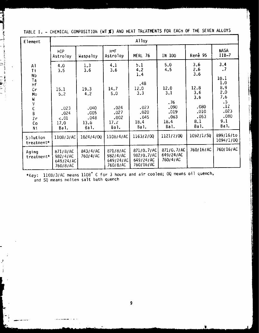
TABLE I. - CHEMICAL COMPOSITION (WT %) AND HEAT TREAT_NTS FOR EACH OF THE SEVEN ALLOYS
Element
AI
Ti
Nb
TaHf
Cr
Mo
WV
C
B
Zr
Co
Ni
Sc,lution
treatment*
Agingtreatment*
*Key:and
Alloy
HIP
Astroloy
4.0
3.5
15.1
5.2
•023
.024
< .01
17.0
Bal.
Waspaloy
1.3
3.6
19.3
4.2
H+F
Astroloy
4.1
3.6
14.7
5.0
.040
.005
.048
13.6
Bal.
.024.027.002
17.ZBal.
MERL 76
5.14.21.4
.48
12.0
3.3
.023
.020
.045
18.4
Bal.
1108131AC
871/8/AC982/4/AC649/24/AC760/8/AC
lO24141OQ
843/4/AC76014/AC
1108/4/AC
871181AC
982141AC
6491241AC760181AC
11631210Q
871/0.7/AC982/0.7/AC649/24/AC7601161AC
IN i00
5.04.5
12.0
3.1
•76•090
.019
.063
18.4
Bal.
1121/21OQ
87110.71AC
6491241AC
760141AC
Rent 95
3.62.63.6
12.8
3.6
3.6
.080
.010
•053
8.1
Bal.
1092/1/SQ
7601161AC
NASAlIB-7
3.4.7
I0.i1.0
8.92.07.6
.5
.12
.023•080
9.1Bal.
8991161to
I0941110Q
1108131AC means 1108 ° C for 3 hours and air coolea; OQ means oil quench,
SQ means molten salt bath quench
7601161AC
9
TABLEII. - MECHANICALPROPERTIESANDFATIGUE
CRACKGROWTHAT 650" C
Material
HIP AstroloyWaspaloyH+FAstroloyMERL76IN 100Ren_ 95NASAlIB-7
Tensilestrength,
MPa
1234126213571365
15Z)
Reductioni n area,percent
36.627.029.325.125.014.210.3
0.2 percentyield
strength,MPa
J m ,,
881957988
102711101122
j 12/8
Fatigue crack
growth rateat 30 MPa_,
mm/cycle
4.6xi0 -44.0xlO -46.6x 10°4
9.4xi0 -4
9.0xlO -414.4xi0-4
11.3xi0 -4
TABLE Ill. - GRAIN SIZE AND GAMMA-PRIME
CONTENT OF EACH ALLOY
Material
HIP AstroloyWaspaloyH+F AstroloyMERL 76IN i00Ren_ 95NASA I IB-7
Grain size, um
Primary Necklace
10-15--m--m_
10-15
Gamma-prime
content,
perc ent
50-70
40-150
50-100
15-20
4-6
50-704-6
442O4260625O59
10
HIPASTROLOY WASPALOY H ÷FASTROLOY
MERL 16 IN100 RENE'g_NASA lIB-/
Figure 1.-The microstructures ofthesevennickel-base superalloys.
1.27cm(0.50 in. )
1.90cmI0.1,_in.)
1.90 cm
CRACKLENGTH
1._cm3.00in.)
Figure 2. - Designof the compacttension specimen. Thicknessof the specimenwas t. _ cm.
II
I 6_°c Q-P|o.33Hz St'
,o-'._ ,ENE,___//,F__ NASAZI_'_II. I_J
:,o-,i Niz! <1 _ H)PAS'r_LOY
_/__ [ , _Vt/CSPIAL:¥1,(
lO 20 40 60 80 I00
AK (MPa
Figure 3, -Thecrackgrowth rates of thesevennickel--_as_superalloys tested infatigue, 4-6
:oo
I0-I
E
i0-2
I0-3
6so° c_ SECONDDWEtLJ/
RENE'g5..... / / _ INlO0
- X7 _ .\HipASTROLOY
III J.. _ z l
IO 20 40 60 80 IO0
AK *MPa,_)
Figure 4. - The crackgrowth ratesof the sevennickel-basesu_ralloys testedin creeo-tatigue. 4"6
FATIGUE CYCL[
I I I
/ I \/ I \
CRE[ P-FATIGUE C_'CLt
I_lqure 5. - The lrachJre _urface of the _.o_'_pa_.t ten,,ton '_pe_.m_,n_. Note th4t
In the r_}ion of ,,Elbl? cr4ck qrowth the _,urla(.e of lhe tah_lue ,,p_0_'_en _,,
fiat while the _reep-fattque spe(imen ,h_pla'v,, ridqe_, ,_h,ch ori(lln4te ,It the
pre(rd_k intertwine.

/,
.o
(a_WASPALOY.
4b_HIP ASIROLOY.
Figure 0 - Transgranular fracture rnorph::)l_), of t,'_aspalo_(a_ and HIP Astrolo_/_b_ tested in fatique. The (,trer,_, intensi_ ranqe _sapproxirnatel_ 20 _,_Pa l,/_.
The direct,_ ° of crack growth is _op to bottom ,n the ser_ pnofo'_ on the left.
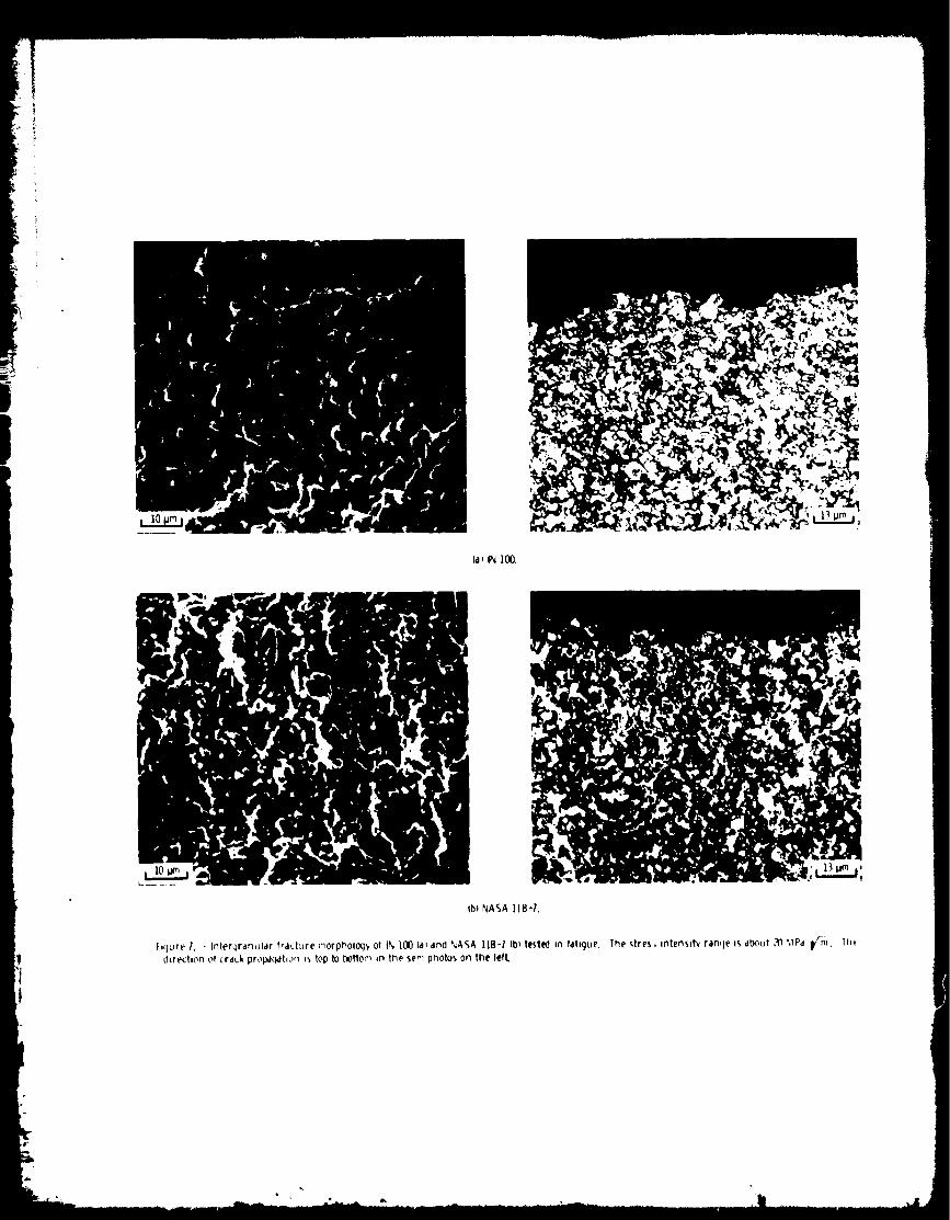
(al IN 100.
(b) NASA IIB-?.
hCJLJr_Z. - Interqrdr_ulclr frdct-Jre morphoIoq'f of tN lO0 (a_and %'ASA IIB-I tbt tested in tdtigue.
_trectton of crduk propa_tion bstop to _ffom =n the ser'_ photos on the left.
The stres, intensl_ ran¢_e is about ,'_ ._Pcl p'_l. The,
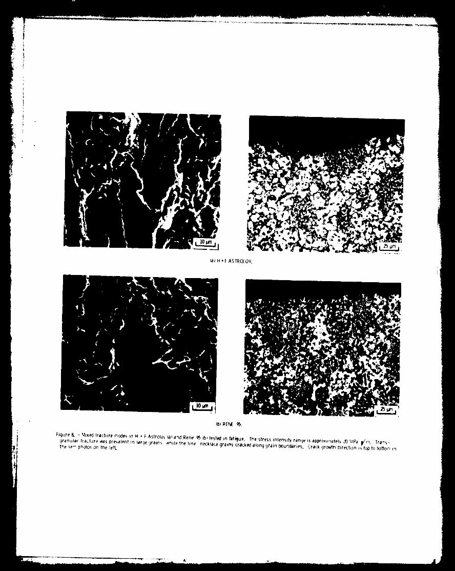
ia)H*F ASTRO(OY.
(b) RENE gS.
Figure 8. - Mixed fra(ture modes in H * I: Astrolo,, (al and Rene g5 qbbtested in fat_ue, rhe stress intensity rdnqe is appro_lmdtel_ ,'0 '_lPd i,/r_. Tr,_ns-9rdnulartheser_ photosfractureon_aSthepre_,alen!left._n large _]raon,, ¢_htle the fine necktaEe gr;=tns (rs(.ked along grain boun(Idrtes. Crack (]rowth direction _ top to bottor'_ in
10-2
|lo"
i
I0-4
RENE'95
)r '-HIP ASTROLOY
_ ', LOWSTRESS11_Sr'_ NO PPW$
MERL76
H,CHSTRESSPPB'S
I I I I J10 20 40 50 80 100
AK (MPa _'ml
Figure IO. - The effectof prior Particleboundiries IPPBI on crick 9rowth riteof MERL70 testedin fatigue i$ illus-tratedabove. At lover stress levels.but similar stress Intensity ranges, thepresence of PPg'S and the crackqr(_,dhrate for MERL76 are dramatically re-duced,allrOiching that of HIP Astroloy.
ibl
Figure q. - A mixecl fracture moCe at hlgh stresses laJ and transqranular frac-
ture at low stresses Ibb were o_served _n fatigue for MERL 7(_ The stress in-
tensity range is al_rolnmatel_ _0 MPa _,'m In both photos The derechon of
crack qrowth is too to bottom
I ........................ ,,

qb_AK • 45 MPa Vm.
figure ||. - The effect of stress in(enslty on the fracture morphoJacJy of HfP
and-forcjed kstrolo_ tested ,n lahc)ue. Cra_ qrowth is influenced by micro-
structure to a greater degree at lower stress intensities. AS the crack cjrows.
se(ondary crackin 9 is more prono,,nced ,rod intercJranu_r fracture in the
fine grain regions becomes less i.romment.
la_WASPALOY.
\
\
(h_HIP ASTROLOY.
hqure 12. - Interqranular fracture morpholo<iy or Vi'aspaloy (a_and HIP Astrolo_/ 4bbunder creep-fatigue test conditions. The stress intens,tv rancje us
approx=_natel_ )5 MPa 1,m. Crack growth direction usfop to bottom for the sere photos On the left,
_1_H + F ASTROLOY.
tbJ RENE' 15.
Figure },3. - Intergranular fracture morphology of HIP and forged Astroloy la) and Rene 15 (bl under creep-fatigue test conditions. The stress intensit_
range is aporoximateh' )5 MPa _ for the Astrotoy and ]0 MPa _ for the Rene qS. Crack growth direction is top to bottom for the sere photos on theleft.
?

5
(a) IN |(_.
,dL .J.
ib_ INASA IiB-7.
Figure 14. - Intergranutar fracture morphology of IN 100 V}_and NASA |18-7 (b) under creep-fatigue test conditions. The stress mtens,t_ rdnge is approx-imatel_ 3.5_,IP,.t I/m for IN I00and _ _,lPa _/r_ for NASA IIBq. Crclr..k growth direction i5 top to bottom for the sere photos cn the lefL

Figure 15. - Mixed fracture mode for _._[RL 10 under creep-fatigue test conditions. Fracture is predonif_antly intergranular: however crackin(i on prior
particle boundaries is observed. The stress intensih range is approximately 25 MPa I)/-_. Crack gro_vtt_ direction is top to bottom _r, the st':'_ _)heto',.
=
_,_ T_IN BOLiF, DAR_ #RACKING.
t
t_= _UBSURfACE CRACKING
Figure 10 - Se_.ondar_ _ra_km< t m _,ls_lo_ under creep-tahque lest corldl_;u_=s.
Fracture Occurs aionQ qralrl Ix_c|rldarlts af_ _'wlrl _o(JnOdrlt% d) Subsurface
cracks tb_ _vere also oOserved t_._d iesser d_qree
}
,:, }"
6500 C: 9(]0 second dwell
Figure 17, - Detailedview o_ridge-likefeaturesseen on the creeo-fatigue
_eci men s.
_L" h_ _ _b_,.. _. . ,-,._ n,,:_._ " _"