Mechanisms of Fatigue Crack Propagation in Metals ... · Mechanisms of Fatigue Crack Propagation in...
14
Material.s Science and Engineering, A 103 (1988) 15-28 15 Mechanisms of Fatigue Crack Propagation in Metals, Ceramics and Composites: Role of Crack Tip Shielding* R. O. RITCHIE (Tenter jor A dvanced Materials, Materials and Chemical Sciences I)ivision, Lawrence Berkeley Laboratoo', and l)~7)artnlenl ~)1" Materials Science and Mineral Engineering Universi O, of (alifornia, Berkeley, (;1 94720 (U.S.A.) (Received March 11. 1988) Abstract Crack tip shielding phenomena, whereby the "effective crack-driving force" actually experienced at the crack tip is locally reduced, are examined with reference to fatigue crack propagation behav- ior in metals, composites and ceramics. Sources of shielding are briefly described in terms of mecha- nisms relying on the production of elastically con- strained zones which envelop the crack (zone shielding), on the generation of wedging, bridging or sliding forces between the crack surfaces (con- tact shielding) and on crack path deflection attd meandering. Examples are taken from the fatigue behavior of high strength lithium-containing aluminum alloys, aluminum alloy-aramid fiber-epoxy laminate composites, and zircon& ceramics. It is shown that, whereas crack tip shielding can provide a potent means of enhancing "resistance" to crack growth, such extrinsic tough- ening mechanisms can result in the apparently anomalous behavior of "small cracks" and to the susceptibili O' of brittle materials to fatigue faihtre. 1. Introduction In fracture mechanics terms, the extension of a crack is driven by the presence of a "'crack- driving force" and opposed by the resistance of the microstructure. Here the crack-driving force is generally defined by some characterizing parameter, such as the stress intensity K t or path- independent integral J, which describes the domi- nant stress and deformation fields in the vicinity of the crack tip. Crack advance is thus restrained by lowering the applied load or by "toughening" the material, e.g. through compositional or mic- *Paper presented at the Workshop on the Mechanics and Physics of Crack Growth: Application to Life Prediction, Keystone, CO, U.S.A., August 4-7, 1987. rostructural modifications which impede adv- ance. In alloy design, it is generally the perceptkm that toughening is achieved by increasing the inherent microstructural resistance (e.g. by coars- ening particle spacings, changing bond strengths, or increasing ductility), a process referred to as intrinsic toughening. However, in many material sytems, particularly with brittle fracture in ceram- ics (see for example ref. 1) and fatigue in metals (see for example ref. 2), the actual source of toughness is distinctly different and arises from mechanisms of crack tip shielding, where tough- ness is achieved, i.e. crack extension is impeded, by mechanical, microstructural and environ- mental factors which locally reduce the crack- driving force, a process referred to as extrinsic toughening. It is the aim of this paper to describe briefly the mechanistic origins of such crack tip shielding and to discuss the general implications of the resultant extrinsic toughening on crack extension behavior under cyclic loading. 2. General considerations of extrinsic toughening 2.1. Crack-driving ]brce The "'driving force" for crack growth is gener- ally described by a field-characterizing param- eter. This is defined by characterizing the stress and deformation fields local to the region at the crack tip, usually through the use of asymptotic continuum analyses, and determining the func- tional form of the singular crack tip field which is appropriate for the primary mechanism of defor- mation. Provided that this field can be considered to "dominate" the local stresses and strains over a region which is large compared with the scale of microstructural deformation and fracture events 0921-5093/88/$3.50 © Elsevier Sequoia/Printed in The Netherlands
Transcript of Mechanisms of Fatigue Crack Propagation in Metals ... · Mechanisms of Fatigue Crack Propagation in...
Material.s Science and Engineering, A 103 (1988) 15-28 15
Mechanisms of Fatigue Crack Propagation in Metals, Ceramics and Composites: Role of Crack Tip Shielding*
R. O. RITCHIE
(Tenter jor A dvanced Materials, Materials and Chemical Sciences I)ivision, Lawrence Berkeley Laboratoo', and l)~7)artnlenl ~)1" Materials Science and Mineral Engineering Universi O, of (alifornia, Berkeley, (;1 94720 (U.S.A.)
(Received March 11. 1988)
Abstract
Crack tip shielding phenomena, whereby the "effective crack-driving force" actually experienced at the crack tip is locally reduced, are examined with reference to fatigue crack propagation behav- ior in metals, composites and ceramics. Sources of shielding are briefly described in terms of mecha- nisms relying on the production of elastically con- strained zones which envelop the crack (zone shielding), on the generation of wedging, bridging or sliding forces between the crack surfaces (con- tact shielding) and on crack path deflection attd meandering. Examples are taken from the fatigue behavior of high strength lithium-containing aluminum alloys, aluminum alloy-aramid fiber-epoxy laminate composites, and zircon& ceramics. It is shown that, whereas crack tip shielding can provide a potent means of enhancing "resistance" to crack growth, such extrinsic tough- ening mechanisms can result in the apparently anomalous behavior of "small cracks" and to the susceptibili O' of brittle materials to fatigue faihtre.
1. Introduction
In fracture mechanics terms, the extension of a crack is driven by the presence of a "'crack- driving force" and opposed by the resistance of the microstructure. Here the crack-driving force is generally defined by some characterizing parameter, such as the stress intensity K t or path- independent integral J, which describes the domi- nant stress and deformation fields in the vicinity of the crack tip. Crack advance is thus restrained by lowering the applied load or by "toughening" the material, e.g. through compositional or mic-
*Paper presented at the Workshop on the Mechanics and Physics of Crack Growth: Application to Life Prediction, Keystone, CO, U.S.A., August 4-7, 1987.
rostructural modifications which impede adv- ance.
In alloy design, it is generally the perceptkm that toughening is achieved by increasing the inherent microstructural resistance (e.g. by coars- ening particle spacings, changing bond strengths, or increasing ductility), a process referred to as intrinsic toughening. However, in many material sytems, particularly with brittle fracture in ceram- ics (see for example ref. 1) and fatigue in metals (see for example ref. 2), the actual source of toughness is distinctly different and arises from mechanisms of crack tip shielding, where tough- ness is achieved, i.e. crack extension is impeded, by mechanical, microstructural and environ- mental factors which locally reduce the crack- driving force, a process referred to as extrinsic toughening.
It is the aim of this paper to describe briefly the mechanistic origins of such crack tip shielding and to discuss the general implications of the resultant extrinsic toughening on crack extension behavior under cyclic loading.
2. General considerations of extrinsic toughening
2.1. Crack-driving ]brce The "'driving force" for crack growth is gener-
ally described by a field-characterizing param- eter. This is defined by characterizing the stress and deformation fields local to the region at the crack tip, usually through the use of asymptotic continuum analyses, and determining the func- tional form of the singular crack tip field which is appropriate for the primary mechanism of defor- mation. Provided that this field can be considered to "dominate" the local stresses and strains over a region which is large compared with the scale of microstructural deformation and fracture events
0921-5093/88/$3.50 © Elsevier Sequoia/Printed in The Netherlands
16
in the vicinity of the tip, the scalar amplitude of the field is taken as the characterizing parameter and can be used as a correlator of crack exten- sion. Best-known examples of this approach are for stationary cracks subjected to tensile opening loads, where for materials obeying a linear elastic or a non-linear elastic constitutive law the asymp- totic crack tip stress, strain and deformation fields are characterized in terms of the stress intensity factor K z or the path-independent integ- ral J respectively (see for example ref. 3). For creeping solids, similar driving forces for crack advance can be defined in terms of constitutive laws for creep, e.g. C* and C(t), which are viscous analogs of J (see for example refs. 4 and 5).
As characterizing parameters remain undeter- mined by the asymptotic analyses, they are gener- ally computed from a complete analysis of the applied loading and geometry. Although these analyses rely on global considerations, they are assumed to guarantee a characterization of the local field. However, where the local near-tip "driving force" actually experienced at the crack tip differs from this nominal or applied "driving force", owing to some local mechanical, micro- structural or environmental phenomenon in the vicinity of the crack tip, the crack can be consid- ered to be experienced crack tip shielding. For small-scale yielding under monotonic or cyclic loading conditions, this can be expressed as
Kti p = K[ - K~ ( 1 )
AKtip= AK-Ks (2)
where Kti p and AKti p a re the local near-tip stress intensity and stress intensity range respectively, K~ is the applied or nominal stress intensity, A K is the applied or nominal stress intensity range, given by Kma x - - Kmin, and K~ is the stress intensity due to shielding. The objective of extrinsic tough- ening is thus to enhance K~.
As rates of subcritical crack growth by mechanisms such as fatigue show a power law dependence with "driving force", extrinsic tough- ening can be extremely potent in reducing crack extension rates. However, since the stress inten- sity due to shielding must be superimposed on the applied values, the prominence of crack tip shielding is largely restricted to materials of low intrinsic toughness or where crack advance can be sustained at low applied driving forces. Ac- cordingly, it can provide a general approach to toughening and thereby controlling the fracture
toughness of ceramics and fatigue crack growth in metals.
2.2. Mechanisms of crack tip shielding It is possible to categorize mechanisms of
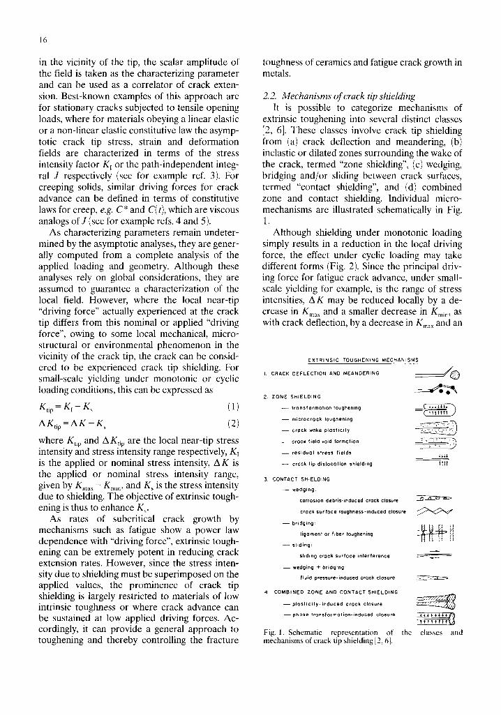
extrinsic toughening into several distinct classes [2, 6]. These classes involve crack tip shielding from (a) crack deflection and meandering, (b) inelastic or dilated zones surrounding the wake of the crack, termed "zone shielding", (c) wedging, bridging and/or sliding between crack surfaces, termed "contact shielding", and (d) combined zone and contact shielding. Individual micro- mechanisms are illustrated schematically in Fig. 1.
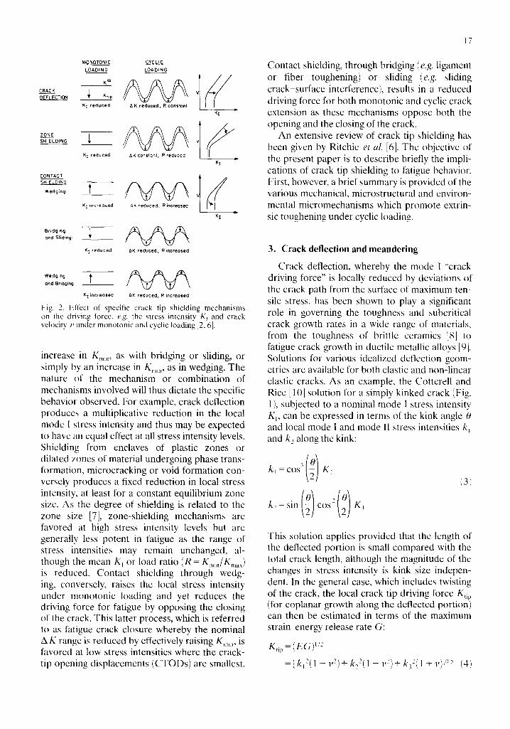
Although shielding under monotonic loading simply results in a reduction in the local driving force, the effect under cyclic loading may take different forms (Fig. 2). Since the principal driv- ing force for fatigue crack advance, under small- scale yielding for example, is the range of stress intensities, A K may be reduced locally by a de- crease in Kma x and a smaller decrease in Km~,l , as with crack deflection, by a decrease in Kma × and an
EXTRINSIC TOUGHENING MECHANISMS
I. CRACK DEFLECTION AND MEANDERING / , / ~
2. ZONE SHIELDING
- - transformation toughening
- - m io roc rock toughening
- - crock woke plosticily ~ _ ~
- - crock f ie ld void format ion " ~ f o ~
- - res idua l stress f i e lds
- - crock t ip d i s loca t ion shie ld ing 11'~t
3. CONTACT SHIELDING
- - wedging:
corrosion debris-induced crock closure
crock surface roughness-induced closure
- - bridging:
ligament or fiber toughening ~ I ]
- - sliding:
Sliding crock surface interference ~
- - wedging + bridging:
fluid pressure-induced crock closure
4. COMBINED ZONE AND CONTACT SHIELDING
- - plast ic i ty- induced crock closure
- - phase t rons fo r rno t ion- induced c losure ~ ~ $ 4 $ ~. ~ ~ / ~
Fig. I. Schematic representation of the classes and mechanisms of crack tip shielding [2, 6].
MONOTONIC LOADING
K Do
CRACK 0EFLECTION KtlP
K! reduced
ZONE SHIELDING ~,
CONT~,C T SHIELDING
Wedging
Bridging and Sliding:
K I reduced
CYCLIC LOADING
~, K reduced, R constont
AK constor~t, R reduced
' K T increosed ~K reduced, R increosed
K I reduced 6K reduced, R increased
# KI
/ K I
Wed i°g t and Bridging:
Kiincreosed ~K reduced, R increosed
Fig. 2. Effect of specific crack tip shielding mechanisms on the driving force, e.g. the stress intensity K~ and crack velocity v under monotonic and cyclic loading [2, 6].
increase in Kmm , as with bridging or sliding, or simply by an increase in Kmi n, as in wedging. The nature of the mechanism or combination of mechanisms involved will thus dictate the specific behavior observed. For example, crack deflection produces a multiplicative reduction in the local mode I stress intensity and thus may be expected to have an equal effect at all stress intensity levels. Shielding from enclaves of plastic zones or dilated zones of material undergoing phase trans- formation, microcracking or void formation con- versely produces a fixed reduction in local stress intensity, at least for a constant equilibrium zone size. As the degree of shielding is related to the zone size [7], zone-shielding mechanisms are favored at high stress intensity levels but are generally less potent in fatigue as the range of stress intensities may remain unchanged, al- though the mean KI or load ratio (R = Kmin/Km~) is reduced. Contact shielding through wedg- ing, conversely, raises the local stress intensity under monotonic loading and yet reduces the driving force for fatigue by opposing the closing of the crack. This latter process, which is referred to as fatigue crack closure whereby the nominal AK range is reduced by effectively raising Kmm, is favored at low stress intensities where the crack- tip opening displacements (CTODs) are smallest.
17
Contact shielding, through bridging (e.g. ligament or fiber toughening) or sliding (e.g. sliding crack-surface interference), results in a reduced driving force for both monotonic and cyclic crack extension as these mechanisms oppose both the opening and the closing of the crack.
An extensive review of crack tip shielding has been given by Ritchie et al. [6]. The objective of the present paper is to describe briefly the impli- cations of crack tip shielding to fatigue behavior. First, however, a brief summary is provided of the various mechanical, microstructural and environ- mental micromechanisms which promote extrin- sic toughening under cyclic loading.
3. Crack deflection and meandering
Crack deflection, whereby the mode I "crack driving force" is locally reduced by deviations of the crack path from the surface of maximum ten- sile stress, has been shown to play a significant role in governing the toughness and subcritical crack growth rates in a wide range of materials, from the toughness of brittle ceramics [8] to fatigue crack growth in ductile metallic alloys [91 . Solutions for various idealized deflection geom- etries are available for both elastic and non-linear elastic cracks. As an example, the Cotterell and Rice [10] solution for a simply kinked crack (Fig. 1), subjected to a nominal mode l stress intensity K~, can be expressed in terms of the kink angle 0 and local mode I and mode II stress intensities k~ and k~ along the kink:
{3)
This solution applies provided that the length of the deflected portion is small compared with the total crack length, although the magnitude of the changes in stress intensity is kink size indepen- dent. In the general case, which includes twisting of the crack, the local crack tip driving force K~i p (for coplanar growth along the deflected portion) can then be estimated in terms of the maximum strain energy release rate G:
K~i p = (EG) I / :
= { k12(] - v 2) + k22( 1 - v 2) + k32(1 + V)} IL5 (4)
18
where k 3 is the local mode III stress intensity, E is Young's modulus and v is Poisson's ratio. For the simply tilted crack in Fig. 1, reduction in crack- driving force for in-plane deflections of, say, 30 ° and 90 ° are thus of the order of 10% and 50% respectively; much larger reductions can be achieved with associated twisting of the crack.
The size, rather than simply the angle, of the deflected crack segment can have an effect on the kinetics of crack advance, as it dictates the extent of crack extension which experiences the reduced driving force. Accordingly, shielding through crack deflection can be more significant in affect- ing subcritical crack growth rates. By considering both the changes in apparent growth rate and the local driving force for repeated (two-dimensional) crack segments involving a deflection angle 0, a deflected distance b and undeflected distance c, the effective crack tip stress intensity range A Kti p and the growth rate da/dN of an idealized (linear elastic) deflected crack have been estimated by Suresh [9] to be
bcos2( O/2)+ c - AKL AKtip b+c (5)
do b c o s O + c ( d a ]
dU ~- ff-+c k ~ ] L
where (AK)L and (da/dN)L are the nominal stress intensity range and growth rate respectively of the linear undeflected mode I crack.
By promoting crack deflection through the inclusion of particles with high aspect ratios, increases in fracture toughness by up to a factor of 3 have been claimed for ceramic materials [ 11]. Moreover, as described below, the phenomenon can be extremely important during the fatigue of metallic alloys where the deflection of the crack path can additionally induce shielding from the wedging of enlarged fracture surface asperities [9, 12].
4. Contact shielding
Contact shielding involves physical contact between mating crack surfaces, either directly, through the presence of fracture surface asperi- ties or with fibers in a composite, or through the presence of an external medium, such as with corrosion debris or the entry of a fluid. The principal mechanisms of such contact are through wedging inside the crack, bridging across the
crack, sliding between crack surfaces and com- binations of these modes. In general, since the degree of shielding will be largest when the extent of crack opening is comparable with the size of the contacting entity, in contrast with zone shield- ing, contact shielding is enhanced at low stress intensities where the CTODs are smallest. Furthermore, where wedging is involved, although significant shielding can be achieved under cyclic loading, the effect under monotonic loads may lead to local increases in the crack tip driving force (antishielding).
4.1. Wedging 4.1.1. Oxide- or corrosion-debris-induced crack closure
It is now realized that insoluble corrosion prod- ducts formed within slowly growing cracks ex- posed to active environments can significantly affect their subsequent crack extension rates. This occurs by a mechanical wedging action which can either promote sustained-load crack- ing or retard cracking under cyclic loads where the size of the products becomes comparable with the CTOD [13-18]. Such shielding causes a reduction in the local stress intensity range through an effective increase in Km~n and has been found to have significant effects on fatigue crack growth at very low near-threshold stress inten- sities. A notable example is where crack surface oxides and calcareous deposits are formed during corrosion fatigue in structural steels tested, respectively, in moist air and sea water (see for example refs. 17 and 18).
The concept of shielding by oxide-induced crack closure can be simply modelled by con- sidering the excess corrosion deposit as a rigid wedge, of thickness s comparable with the CTOD, extending along the crack length a dis- tance 2l behind the crack tip [16]. On the assump- tion of only a mechanical closure phenomenon arising from the wedge and if hysteresis and inelastic effects are ignored, the resultant stress intensity at the crack tip is given by
sE KR - 4(1 - v2)(erl) '/2 (6)
During a fatigue cycle, contact between the crack surfaces will occur on unloading when the stress intensity reaches a value K R -Kcj , referred to as the closure stress intensity. Using the conven- tional terminology, the driving force for crack
advance is reduced from the nominal A K to an effective value, given by
AK~,ff=K ...... - K , , (7)
provided that the excess oxide thickness exceeds the minimum crack-opening displacement imposed by the fatigue cycle. In terms of eqn. (2), A Kcr f = A K~ip, with the shielding stress intensity given by
K~ = [0 (Kd < K.,~,) (8)
It should be noted from eqn. (6) that deposits in the immediate vicinity of the crack tip have a dominating influence in the development of shielding.
Contact shielding during fatigue crack growth from crack closure induced by this mechanism is promoted by (a) small CTODs (i.e. at AK levels comparable with the size of the debris), (b) low load ratios, which facilitate fretting between the crack walls through small CTODs, (c) highly oxidizing media, which generate excess corrosion deposits, (d) rough fracture surfaces, which at low AK levels again facilitate fretting, and (el lower strength materials, where again the extent of corrosion debris is enhanced owing to greater fretting [ 19].
As wedge shielding is only relevant where the size of the wedge and the CTODs are compar- able, oxide-induced closure is most effective dur- ing crack propagation at near-threshold levels. For example, near-threshold fatigue crack growth rates at low load ratios in steels are significantly faster in dry helium gas, and slower in water or steam, than in room air [15, 19]. This surprising effect can be primarily attributed to the genera- tion of thicker oxide films, and hence greater shielding, for tests in oxidizing environments. In such lower strength materials, the thickness of these films can be far larger than the natural limiting oxide thickness owing to fretting oxida- tion between the crack walls. The accumulation of debris here arises from a continual breaking and re-forming of oxide scale due to repeated contact and inelastic mode II displacements between the crack surfaces. Where the oxide is thickened primarily by fretting, the shielding effect is decreased at high load ratios or at higher A K levels where the CTODs are larger. However, in more oxidizing environments where the oxide is thickened thermally, the wedge shielding can be retained at high load ratios [18].
19
Aside from its contribution to the role of environment and load ratio in influencing near- threshold behavior, contact shielding from oxide- induced closure also results in a strong effect of yield strength o n A Kth values, as oxide films are enhanced in lower strength materials. However, with steels of higher tensile strength and in most aluminum alloys, fretting oxidation appears much reduced, with the result that, except in highly oxidizing environments, the oxide film remains small compared with the CTODs such that the contribution to shielding from this mechanism becomes negligible [19].
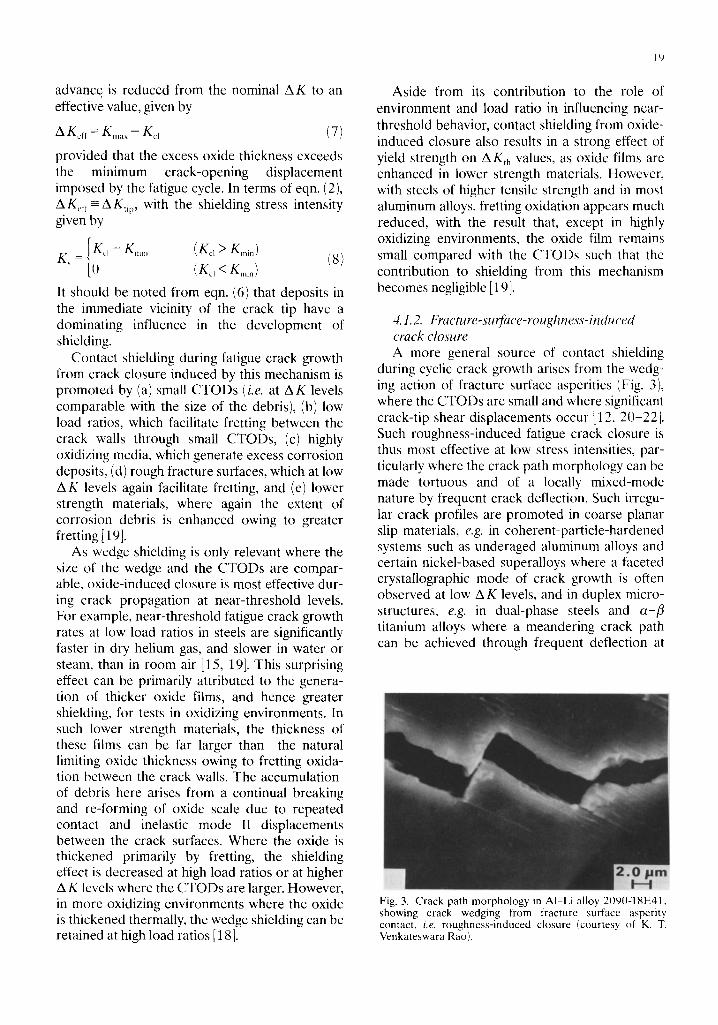
4.1.2. Fracture-surface-roughness-induced crack closure A more general source of contact shielding
during cyclic crack growth arises from the wedg- ing action of fracture surface asperities (Fig. 3), where the CTODs are small and where significant crack-tip shear displacements occur [12, 20-22]. Such roughness-induced fatigue crack closure is thus most effective at low stress intensities, par- ticularly where the crack path morphology can be made tortuous and of a locally mixed-mode nature by frequent crack deflection. Such irregu- lar crack profiles are promoted in coarse planar slip materials, e.g. in coherent-particle-hardened systems such as underaged aluminum alloys and certain nickel-based superalloys where a faceted crystallographic mode of crack growth is often observed at low A K levels, and in duplex micro- structures, e.g. in dual-phase steels and cc-fi titanium alloys where a meandering crack path can be achieved through frequent deflection at
Fig. 3. Crack path morphology in AI-Li alloy 2090-T8E41, showing crack wedging from fracture surface asperity contact, i.e. roughness-induced closure {courtesy of K. T. Venkateswara Rao).
20
the harder phase or by following a continuous softer phase [19, 23, 24].
The concept of shielding by roughness- induced closure arises from the premature con- tact of fracture surface asperities on unloading due to mismatch from the irreversible nature of inelastic crack tip displacements and slip step oxidation. The extent of wedge shielding thus depends on the degree of fracture surface rough- ness and the extent of mode II crack tip dis- placements. For example, from simple two- dimensional geometric modelling of the process, the closure stress intensity at the point of first asperity contact has been given as [12]
K~, = Km,x 1 + 27XJ (9)
where y is a measure of surface roughness taken as the ratio of height h to width w of asperities and X is the ratio of mode II to mode I crack tip displacements. Although only a first-order model, experimental results in a range of ferrous and non-ferrous alloys have been found to be in reasonable agreement with this relationship.
Contact shielding during fatigue crack growth from roughness-induced closure is similarly most effective at low stress intensity ranges. It is pro- moted by (a) small CTODs comparable with the size of the asperities, (b) low load ratios, again to minimize the CTOD, (c) inelastic crack tip defor- mation and oxidation [25] of slip steps, which can lead to a mismatch of mating portions of the crack surfaces on unloading, (d) small plastic zone sizes, of the order of the grain size, which encourages single shear (stage I) mechanisms of crack advance, (e) coarse-grained materials and microstructures hardened with coherent shear- able precipitates capable of inducing coarse planar slip, where crack paths are crystallo- graphic, and (f) crack deflection mechanisms, induced by stress state, environment, duplex microstructures and load excursions, where crack paths may be highly non-linear.
Roughness-induced crack closure has been found to play a significant role in influencing fatigue crack growth in a wide range of materials. For example, the beneficial effects in reducing near-threshold crack growth rates (at low load ratios) of coarse grain sizes in ferritic steels and titanium alloys (see for example ref. 26), under- aged or planar slip microstructures in precipita- tion-hardened aluminum alloys and nickel-based
alloys (see for example ref. 25), and dual-phase microstructures in steels and a - f l titanium alloys (see for example ref. 24), have been directly traced to enhanced shielding from rougher frac- ture surfaces. The largest effects, however, are seen in duplex microstructures, as shown by results for duplex ferritic-martensitic structures in low carbon steels (see for example refs. 23 and 24). By modifying the proportion and primarily the morphology of the two phases by intercritical heat treatment, significant deflection of the crack path can be achieved (Fig. 3), with corresponding large increases in closure (i.e. Kc,/Km, x approach- ing 0.9). The results obtained from Fe-2wt.%Si- 0.1wt.%C and AISI 1008 steels is threshold AKth values of approximately 20 MPa m '/2 without loss in strength, thought to be the largest thresholds reported to date for a metallic material. However, consisent with extrinsic toughening mechanisms, crack initiation resistance (evaluated in terms of the fatigue limit) is not similarly enhanced [24].
4.2. Bridging Crack bridging is most prominent in whisker-
and fiber-reinforced composites where the matrix fails, leaving a region of unbroken fibers spanning the crack wake; the intact fibers act as bridges and inhibit crack opening. Such shielding is pro- moted in ceramic matrix composites where inter- face debonding occurs, i.e. where the fibers are strong but the interracial shear strength between fiber and matrix is weak. This topic has recently been reviewed by Evans [1].
Work on the role of crack bridging in influenc- ing the fracture and fatigue of metal matrix composites is considerably less advanced, in part because many such composites are designed with strong fiber-matrix interfaces and thus do not develop crack bridging to any significant degree. An exception to this, however, is the A R A L L ~ (registered trademark of Alcoa) laminate com- posite alloys which consist of thin sheets of alu- minum alloy bonded together by an aramid-fiber-reinforced epoxy adhesive. Since the strength of the epoxy-fiber interface is com- paratively weak, crack propagation in these hybrid alloys is impeded both by delamination along the interface and by consequent bridging of the unbroken laminated sheets [27]. These materials have been shown to be extremely resis- tant to fatigue crack growth in orientations per- pendicular to the plane of the aramid-epoxy sheets [27, 28], with the effect becoming more
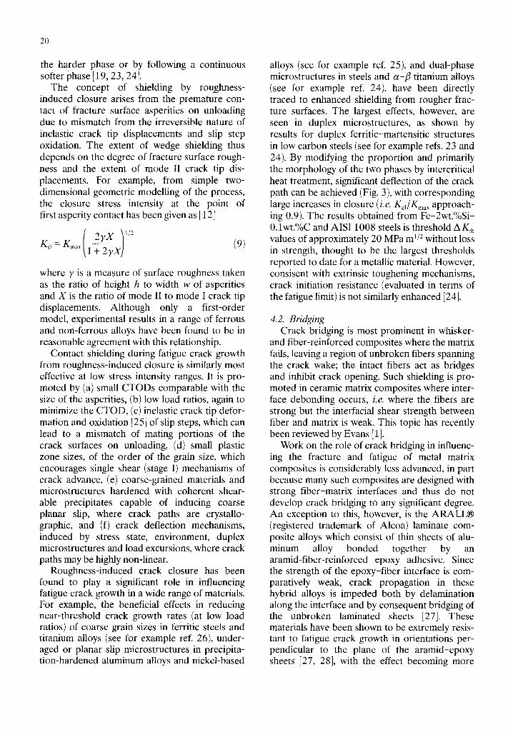
pronounced with increasing crack length as the bridging zone develops in the wake of the crack tip (Fig. 4).
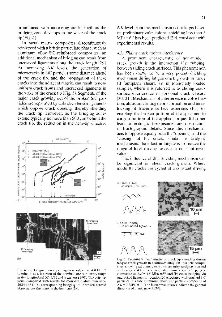
In metal matrix composites discontinuously reinforced with a brittle particulate phase, such as aluminum alloy-SiC-reinforced composites, an additional mechanism of bridging can result from uncracked ligaments along the crack length [29]. At increasing A K levels, the generation of microcracks in SiC particles some distance ahead of the crack tip, and the propagation of these cracks into the adjacent matrix, can result in non- uniform crack fronts and uncracked ligaments in the wake of the crack tip (Fig. 5). Segments of the major crack growing out of the broken SiC par- ticles are separated by unbroken tensile ligaments which oppose crack opening, thereby shielding the crack tip. However, as the bridging zones extend typically no more than 500/~m behind the crack tip, the reduction in the near-tip effective
10 +
AK (ksi-in ''2) 2 5 10 20
10 ~
z 10"
~d
~ 10"
~ 10 -+o
~ t0"?
ld (a)
2024 T351 IT-L] / ARALL-2 [CracktIFiber (90°)] ARALL-2 [Crack±Fiber (0°)] • f
1
i T T T T 'Threshotd" . . . . , 5 10 20
STRESS INTENSITY RANGE, AK (MPa+rn '~)
10 .+
10 "~
10' 2.
10' ~ Z
10"
1(:£ '°
3O
Fig. 4. (a', Fatigue crack propagation rates for ARALL-2 Laminate, as a function of the nominal stress intensity range in the longitudinal (0°; LT) and transverse (90°; TL) orienta- tions, compared with results for monolithic aluminum alloy 2024-T351; (b) corresponding bridging of unbroken aramid fibers across the crack in the laminate [28].
21
A K level from this mechanism is not large; based on preliminary calculations, shielding less than 3 MPa m ~ '~- has been predicted [29], consistent with experimental results.
4.3. Sliding crack surface interference A prominent characteristic of non-mode I
crack growth is the interaction !i.e. rubbing) between sliding crack surfaces. This phenomenon has been shown to be a very potent shielding mechanism during fatigue crack growth in mode III (antiplane shear), i.e. in torsionally loaded samples, where it is referred to as sliding crack surface interference or torsional crack closure [30, 31J. Mechanisms of interference involve fric- tion, abrasion, fretting debris formation and inter- locking of fracture surface asperities (Fig. 6), enabling the broken portion of the specimen to carry a portion of the applied torque. It further leads to heating of the specimen and obstruction of fractographic details. Since this mechanism acts to oppose equally both the "opening" and the "closing" of the crack, similar to bridging mechanisms the effect in fatigue is to reduce the range of local driving force, at a constant mean value.
The influence of this shielding mechanism can be significant on shear crack growth. Where mode III cracks are cycled at a constant driving
a) Crack clcsure via aspenty wedging
b) Crack bridging vqa uncracked ligaments
Fig. 5. Prominent mechanisms of crack tip shielding during fatigue crack growth in aluminum alloy SiC particle compo- sites, showing (a) crack closure via asperity wedging (marked at locations A) in a coarse aluminum alloy-SiC particle composite at A K = 4 . 5 MPa m ~:: and (b) crack bridging via uncracked ligaments (location B) associated with cracked SiC particles in a fine aluminum alloy-SiC particle composite at A K - 7 MPa m ~/2. The horizontal arrows indicate the general direction of crack growth I29].
22
force, growth rates decelerate progressively by over an order of magnitude with increasing crack size. The effect is enhanced at larger crack lengths, particularly where mode I or mode III branch cracks form adjacent to the radial fracture surface. Shielding is decreased, however, at higher cyclic torques where the larger crack tip plastic zones permit larger crack openings.
Provided that a fracture-mechanics charac- terization of mode III crack growth without accounting for such shielding from crack surface interference is simply not feasible, as no unique growth rate can be associated with any nominal value of A KIH, or equivalent non-linear elastic "driving force" AFm [30, 32]. Accordingly, (upper bound) growth rate behavior usually is obtained, either by superimposing a small mean tensile load [30] or by extrapolating (da/dN)iil vs. crack length a curves (at a constant nominal driving force) to a fictitious zero crack length [33].
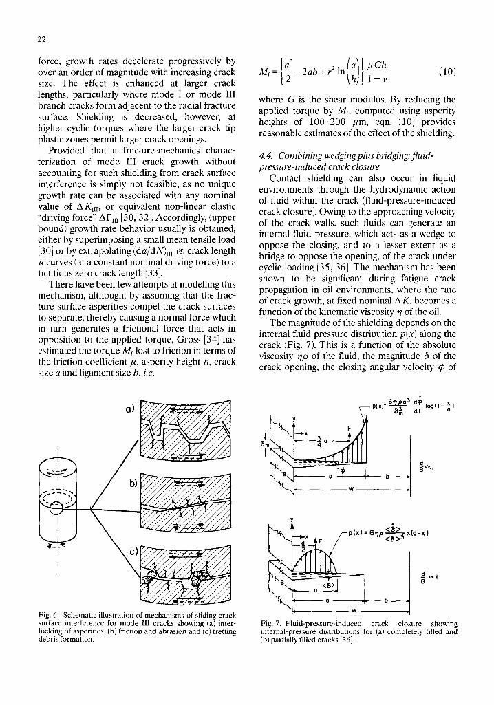
There have been few attempts at modelling this mechanism, although, by assuming that the frac- ture surface asperities compel the crack surfaces to separate, thereby causing a normal force which in turn generates a frictional force that acts in opposition to the applied torque, Gross [34] has estimated the torque Mf lost to friction in terms of the friction coefficient ~, asperity height h, crack size a and ligament size b, i.e.
Fig. 6. Schematic illustration of mechanisms of sliding crack surface interference for mode III cracks showing (a) inter- locking of asperities, (b) friction and abrasion and (c) fretting debris formation.
If (:)} Mf = - 2 a b + r 2 In j~Gh (10) l - v
where G is the shear modulus. By reducing the applied torque by Mr, computed using asperity heights of 100-200 ~m, eqn. (10) provides reasonable estimates of the effect of the shielding.
4. 4. Combining wedging plus bridging:fluid- pressure-induced crack closure
Contact shielding can also occur in liquid environments through the hydrodynamic action of fluid within the crack (fluid-pressure-induced crack closure). Owing to the approaching velocity of the crack walls, such fluids can generate an internal fluid pressure, which acts as a wedge to oppose the closing, and to a lesser extent as a bridge to oppose the opening, of the crack under cyclic loading [35, 36]. The mechanism has been shown to be significant during fatigue crack propagation in oil environments, where the rate of crack growth, at fixed nominal A K, becomes a function of the kinematic viscosity r/of the oil.
The magnitude of the shielding depends on the internal fluid pressure distribution p(x) along the crack (Fig. 7). This is a function of the absolute viscosity r/p of the fluid, the magnitude 6 of the crack opening, the closing angular velocity ~b of
Y F
6"r/p 0 3 d~ x P(~I= 8~ ~-Io~(n-~)
y
< 8 > o
B ----2 =-- cl <<I
o W :!: b
Fig. 7. Fluid-pressure-induced crack closure showing internal-pressure distributions for (a) completely filled and (b) partially filled cracks [36].
the crack walls, and most importantly the extent d of fluid penetration into the crack. Solutions, for a fatigue crack of length a, give [36]
~lpa ~ log-(1 x] la) 6 p,x)' ' = d m ; - a ] c~ (1
for an edge crack completely filled with fluid (d/a = 1), and
6 r/p(d) p(x) = ~,~x(d-x) ( l ib)
for a partially filled edge crack (d /a<l ) . The extent d of fluid penetration can be assessed from capillary flow arguments in terms of the fluid surface tension X~. and wetting angle fl as
d 2 ( / ) _ r l c o s f i i ( (~ ) ( t ) dt (12) 3 y/p /~
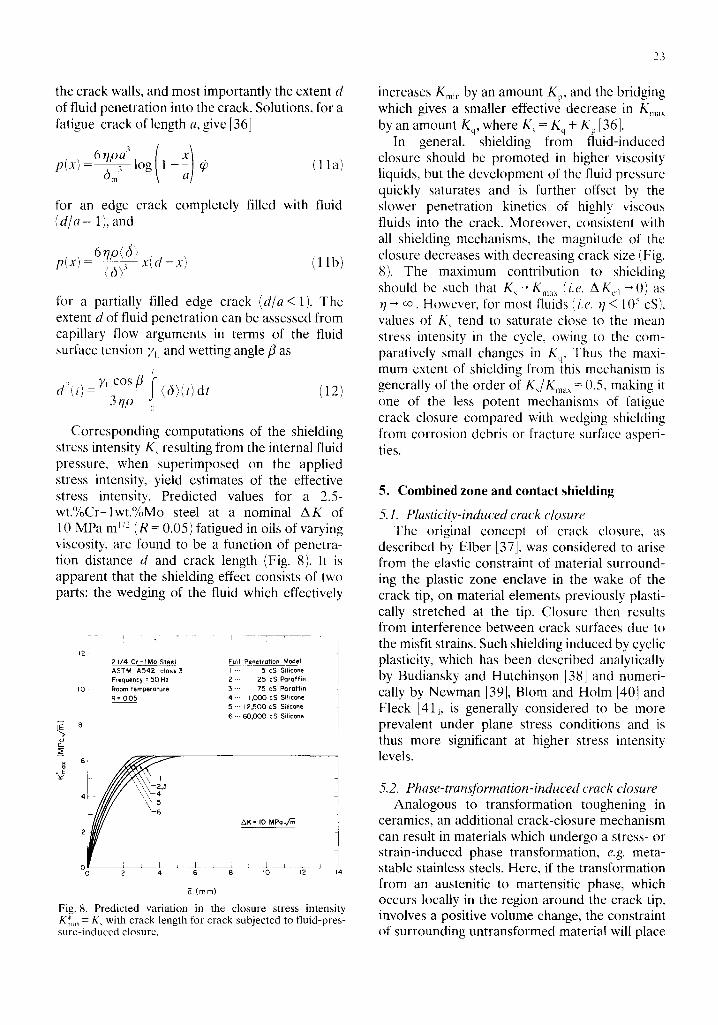
Corresponding computations of the shielding stress intensity K~ resulting from the internal fluid pressure, when superimposed on the applied stress intensity, yield estimates of the effective stress intensity. Predicted values for a 2.5- wt.%Cr-lwt.%Mo steel at a nominal A K of 10 MPa m ~/~ (R = 0.05) fatigued in oils of varying viscosity, are found to be a function of penetra- tion distance d and crack length (Fig. 8). It is apparent that the shielding effect consists of two parts: the wedging of the fluid which effectively
,2! 21/4 Cr - I Mo Steel Full Penetration Model ASTM A542 class3 I ' " 5 cS Silicone Frequency = 50 Hz 2 "" 25 cS Paraffin
I0 , Room temperature 3 ,-- 75 cS Paraffin R = 005 4 "" 1,000 cS Silicone
5 "'" 12,500 cS Silicone 6 ... 60,000 cS Silicone
Y_
"J i i
"! I////
0 L : i = .A_ __J_ ~ 0 2 4 6 8 I0 12 14
8 ( ram)
Fig. 8. Predicted variation in the closure stress intensity Km~,~ - K, with crack length for crack subjected to fluid-pres- sure-induced closure.
23
increases Kmm by an amount Kp, and the bridging which gives a smaller effective decrease in K ...... by an amount Kq, where K, = Kq + Kp [36].
In general, shielding from fluid-induced closure should be promoted in higher viscosity liquids, but the development of the fluid pressure quickly saturates and is further offset by the slower penetration kinetics of highly viscous fluids into the crack. Moreover, consistent with all shielding mechanisms, the magnitude of the closure decreases with decreasing crack size (Fig. 8). The maximum contribution to shielding should be such that K~- 'K ...... (i.e. AK~,,~0) as r/--, co. However, for most fluids (i.e. q < 105 cS), values of K~ tend to saturate close to the mean stress intensity in the cycle, ()wing to the com- paratively small changes in Kq. Thus the maxi- mum extent of shielding from this mechanism is generally of the order of K~/Km~ X = 0.5, making it one of the less potent mechanisms of fatigue crack closure compared with wedging shielding from corrosion debris or fracture surface asperi- ties.
5. Combined zone and contact shielding
5.1. Plasticity-induced crack closure The original concept of crack closure, as
described by Elber [37], was considered to arise from the elastic constraint of material surround- ing the plastic zone enclave in the wake of the crack tip, on material elements previously plasti- cally stretched at the tip. Closure then results from interference between crack surfaces due to the misfit strains. Such shielding induced by cyclic plasticity, which has been described analytically by Budiansky and Hutchinson [38] and numeri- cally by Newman [39], Blare and Holm [40] and Fleck [41], is generally considered to be more prevalent under plane stress conditions and is thus more significant at higher stress intensity levels.
5,2. Phase-transformation-induced crack closure Analogous to transformation toughening in
ceramics, an additional crack-closure mechanism can result in materials which undergo a stress- or strain-induced phase transformation, e.g. recta- stable stainless steels. Here, if the transformation from an austenitic to martensitic phase, which occurs locally in the region around the crack tip, involves a positive volume change, the constraint of surrounding untransformed material will place
24
such regions under compression. Simple analysis for purely dilational strains under monotonic loading suggest the shielding to be of the order of [73
0.22 K~- 2 6TErt 1/2 (13)
l - v
where eT is the transformation strain and rt is the width of the transformed zone. However, the effect in fatigue has not been carefully docu- mented, nor analyzed for the realistic case where deformation involves significant deviatoric strains under cyclic loading conditions.
6. Implications of crack tip shielding
As the majority of shielding mechanisms act predominantly on the crack wake, the direct implications of crack propagation dominated by shielding, in addition to a reduced cracking rate from the lower local driving force, is a crack-size- dependent behavior, i.e. a lack of crack size simil- itude.
First, the material will show resistance curve fracture toughness behavior where the driving force to sustain cracking will increase with increasing crack length (until steady state). Such R curves are common in ductile metals, where zone shielding from prior plastic zones left in the wake of the crack induces a lower strain singu- larity ahead of the til6 (cf the 1/r strain singularity for a fully plastic stationary crack with the ln(1/r) singularity for a non-stationary crack [42]). Marked R curve toughness behavior is also evi- dent in ceramics and ceramic composites (see for example ref. 1), where shielding can occur from transformation or microcrack toughening and from fiber crack bridging respectively, and in rocks, where shallower curves have been reported owing to wedging and microcracking phenomena [43].
Second, microstructural factors known to be beneficial for resistance to crack initiation and the growth of small cracks may have a very different effect on the growth of long cracks [44]; this fol- lows because the role of extrinsic mechanisms becomes negligible where the crack wake is small or non-existent. For example, in steels, increasing yield strength or decreasing grain size results in lower thresholds for (long) crack growth, and yet higher thresholds for crack initiation, i.e. higher fatigue Limits [45].
Third, "small-crack" effects (see for example refs. 44-47) are to be expected since, at the same nominal driving force, the small crack may ex- perience a higher local driving force, owing to decreased shielding, causing it to propagate at a rate in excess of that of the long crack. In addi- tion, since shielding effects will be minimized for small cracks (i.e. typically smaller than 1 mm), the microstructural factors affecting long- and small- crack growth may be very different. For example, grain size, texture, slip character and precipitate phase distribution appear to have a relatively minor influence on small-crack growth [47]; yet these factors have a significant influence on long- crack growth rates, primarily through their effect on crack closure and deflection.
Examples of some of these effects are now dis- cussed with reference to the fatigue behavior of A1-Li alloys and of zirconia ceramics.
6.1. Fatigue of Al-Li alloys The recent development of high strength alu-
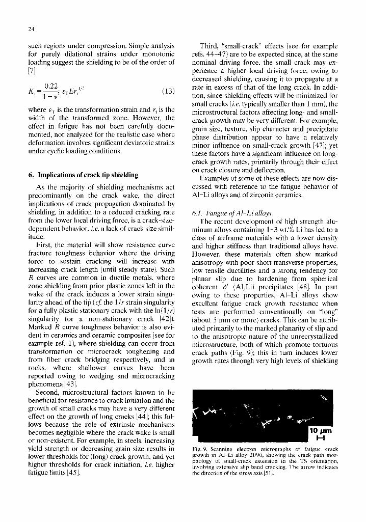
minum alloys containing 1-3 wt.% Li has led to a class of airframe materials with a lower density and higher stiffness than traditional alloys have. However, these materials often show marked anisotropy with poor short transverse properties, low tensile ductilities and a strong tendency for planar slip due to hardening from spherical coherent 6' (A13Li) precipitates [48]. In part owing to these properties, A1-Li alloys show excellent fatigue crack growth resistance when tests are performed conventionally on "long" (about 5 mm or more) cracks. This can be attrib- uted primarily to the marked planarity of slip and to the anisotropic nature of the unrecrystallized microstructure, both of which promote tortuous crack paths (Fig. 9); this in turn induces lower growth rates through very high levels of shielding
Fig. 9. Scanning electron micrographs of fatigue crack growth in A1-Li alloy 2090, showing the crack path mor- phology of small-crack extension in the TS orientation, involving extensive slip band cracking. The arrow indicates the direction of the stress axis [51].
from crack deflection and crack closure from enhanced asperity contact [49-56].
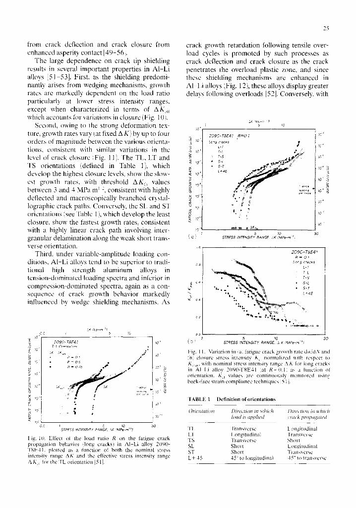
The large dependence on crack tip shielding results in several important properties in AI-Li alloys [51-53]. First, as the shielding predomi- nantly arises from wedging mechanisms, growth rates are markedly dependent on the load ratio particularly at lower stress intensity ranges, except when characterized in terms of A K,, which accounts for variations in closure (Fig. 10).
Second, owing to the strong deformation tex- ture, growth rates vary (at fixed A K) by up to four orders of magnitude between the various orienta- tions, consistent with similar variations in the level of crack closure (Fig. 11 ). The TL, LT and TS orientations (defined in Table 1), which develop the highest closure levels, show the slow- est growth rates, with threshold A K~ values between 3 and 4 MPa m ~:, consistent with highly deflected and macroscopically branched crystal- lographic crack paths. Conversely, the SL and ST orientations (see Table 1 ), which develop the least closure, show the fastest growth rates, consistent with a highly linear crack path involving inter- granular delamination along the weak short trans- verse orientation.
Third, under variable-amplitude loading con- ditions, AI-Li alloys tend to be superior to tradi- tional high strength aluminum alloys in tension-dominated loading spectra and inferior in compression-dominated spectra, again as a con- sequence of crack growth behavior markedly influenced by wedge shielding mechanisms. As
10 + -d
tO +
! 0 '
g
t O "
lO 0 5
2K (ksl-m :) 6 ; 5 10
2 0 9 0 - T8E41 T-L Orientation
2K kKe~ , ,~ R = 0 1 ,~" R = 0 5 . #a,e ~
• R = 0 75 ~
a •
I
{ .
I I 5 ~0
STRESS INTENSITY RANGE, kK (MPa-rn ''~)
tO ̧ `
10
~0 +
10
lO +
10 o
30
Fig. IlL Effect of the load ratio R on the fatigue crack propagation behavior (long cracks) in A1-Li alloy 2090- TgE41 , plotted as a function of both the nominal stress intensity range AK and the effective stress intensity range A/xct t for the TL orientation ]511.
25
crack growth retardation following tensile over- load cycles is promoted by such processes as crack deflection and crack closure as the crack penetrates the overload plastic zone, and since these shielding mechanisms are enhanced in AI-Li alloys (Fig. 12), these alloys display greater delays following overloads [52]. Conversely, with
70 ̧`
ZK ( k s l - m :J I 5 lO
yo" e2
g ~0 10 <
lO '
!0
( a )
+ 0 8 4
u o 4
2090 -TRE41 R = O . l
Long cracks f L-T • r-~ .%:<, T-S ~a~
• S-L ~ * " 4 ~+ "
2,72L ° d
5 STRESS INTENSITY RANGE, AK (MPa-rn '~)
1 0 J
2 0 9 0 - T 8 E 4 l
R = 0 1 Long cracks
• , . . , , . . _ "N LT: • ,, T-5
i . ~ * S-L ..~ ., ~ • S-T
• . % . ' ~ 7 ~ ' ~ L+,,s
+'~+o ~¢- : * !, ~,+
lO"
10 +
;0" i
I0'
lO '
tO o
10 '
30
0 c 2 5 10 30
( b ) STRESS INTENSITY RANGE, A g (MPa-rn'"O
Fig. 11. Variation in <a) fatigue crack growth rate d a / d N and <b) closure stress intensity K d normalized with respect to K,,,~, with nominal stress intensity range A K for hmg cracks in AI Li alloy 2090-T8E41 lal R - - 0 . 1 : as a function of orientation. /~d values are continuously monitored using back-face strain compliance techniques [51 I.
TABLE 1 Definition oforientations
OHentation Direction in wttich l)lrecti(m in which load i.s applied crack propagated
TL Transverse Longitudinal LT Longitudinal Transverse TS Transverse Shot! SL Short Longitudinal ST Short Transverse L+ 45 45 ° to longitudinal 45 ° to t ransverse
26
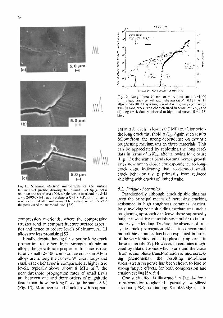
I - . , . , . , pill c H
Fig. 12. Scanning electron micrographs of the surface fatigue crack profile, showing the original crack tip (a) prior to, (b) at and (c) after a 100% single tensile overload in AI-Li alloy 209(/-TSE41 at a baseline AK of 8 MPa m ~/2. Imaging was performed after unloading. The vertical arrows indicate the position of the overload event [52].
compression overloads, where the compressive stresses tend to compact fracture surface asperi- ties and hence to reduce levels of closure, A1-Li alloys are less promising [53].
Finally, despite having far superior long-crack properties to other high strength aluminum alloys, the growth rate properties for microstruc- turally small (2-500/~m) surface cracks in A1-Li alloys are among the fastest. Whereas long- and small-crack behavior is comparable at higher A K levels, typically above about 8 MPa m j/2, the near-threshold propagation rates of small flaws are between one and three orders of magnitude faster than those for long flaws (at the same AK) (Fig. 13). Moreover, small-crack growth is appar-
&K (ks~-tn ''~ ) 0 5 1 5 10
_~ tO ~
2090-TBE41 Small cracks Long cracks
:~ L-T • lO ~ T-L . . . . . . T-s . . . . . .
.~ 10 '
10""
10" . ,~
AK I 5K £J 3KEF ~ ~, R = 0 75 • R = 0 1
1 0 " R=O I J
0 5 f 5 ~0 STRESS INTENSITY RANGE, .~K (MPa-m '~)
. . v f
10""
10 ~
lO °
~0" 7z
,o.9 • 10" "~ #e, cvc~.
10"
i0 .'o
30
Fig. 13. Long (about 10 mm or more) and small (l-1000 /~m) fatigue crack growth rate behavior (at R = 0.1) in AI-Li alloy 2090-TSE41 as a function of A K, showing comparison with (i) long-crack data characterized in terms of AKc, and (ii) long-crack data monitored at high load ratios (R =0.75) [561.
ent at AK levels as low as 0.7 MPa m 1/2, far below the long-crack threshold AKth. Again such results follow from the strong dependence on extrinsic toughening mechanisms in these materials. This can be appreciated by replotting the long-crack data in terms of AK~rr, after allowing for closure (Fig. 13); the scatter bands for small-crack growth rates now are in closer correspondence to long- crack data, indicating that accelerated small- crack behavior results primarily from reduced shielding with cracks of limited wake.
6.2. Fatigue of ceramics Paradoxically, although crack tip shielding has
been the principal means of increasing cracking resistance in high toughness ceramics, particu- larly involving zone-shielding mechanisms, such a toughening approach can leave these supposedly fatigue-insensitive materials susceptible to failure under cyclic loading. To date, the absence of true cyclic crack propagation effects in conventional monolithic ceramics has been explained in terms of the very limited crack tip plasticity apparent in these materials [57]. However, in ceramics tough- ened by dilatant zones which surround the crack (from in situ phase transformation or microcrack- ing phenomena), the resulting non-linear stress-strain response has been shown to lead to strong fatigue effects, for both compression and tension cycling [58, 59].
One such effect is illustrated in Fig. 14 for a transformation-toughened partially stabilized zirconia (PSZ) containing 9mol.%MgO, sub-
10 .2
10 -3
10 " (1.)
10 '
10 -~
>L 10-'
o _o 10 -~ > _~ 10 ~
10 -'°
1 0 11
10 -~
I =R = O 10 Fatigue crack growth in NZ i :
• = R = O 10 Fatigue crack growth in AIR = R = O 10 Fatigue crack growth in H20 I
• = S l o w crack growth m air --Slow crack growth m N20 {t
cvchc ; o J d i n g
t t
, , /l! 4 I
/ --[ ig . -
' I [
I #
z/ $ ~ $ t a l n a d l o a d i n g i
t
.Z I
3 4 5 6 I
Stress Intensity, Kma x (MPa-m '/2)
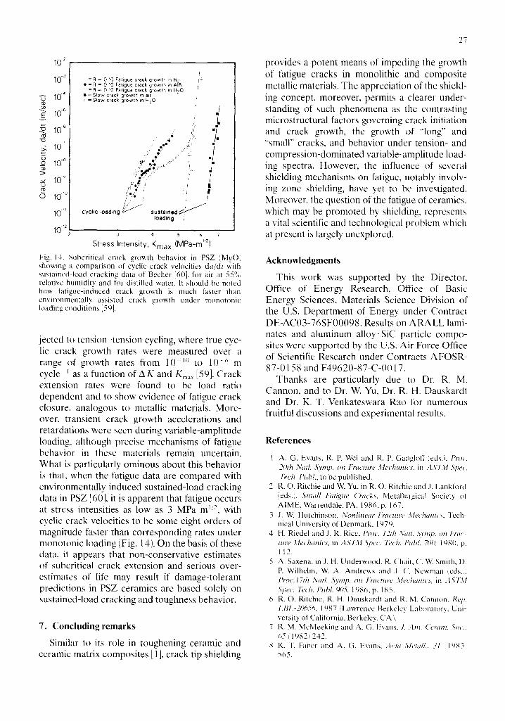
Fig. 14. Subcritical crack growth behavior in PSZ (MgO) showing a comparison of cyclic crack velocities da/dt with sustained-load cracking data of Becher [60], for air at 55% relative humidity and for distilled water. It should be noled how fatigue-induced crack growth is much faster than environmentally assisted crack growth under monotonic loading conditions [59].
jected to tension-tension cycling, where true cyc- lic crack growth rates were measured over a range of growth rates from l0 v~ to 10 -~' m cycle i as a function of AK and K ...... [59]. Crack extension rates were found to be load ratio dependent and to show evidence of fatigue crack closure, analogous to metallic materials. More- over, transient crack growth accelerations and retardations were seen during variable-amplitude loading, although precise mechanisms of fatigue behavior in these materials remain uncertain. What is particularly ominous about this behavior is that, when the fatigue data are compared with environmentally induced sustained-load cracking data in PSZ 160], it is apparent that fatigue occurs at stress intensities as low as 3 MPa m ~'-', with cyclic crack velocities to be some eight orders of magnitude faster than corresponding rates under monotonic loading (Fig. 14). On the basis of these data, it appears that non-conservative estimates of subcritical crack extension and serious over- estimates of life may result if damage-tolerant predictions in PSZ ceramics are based solely on sustained-load cracking and toughness behavior.
7. Concluding remarks
Similar to its role in toughening ceramic and ceramic matrix composites [1 J, crack tip shielding
27
provides a potent means of impeding the growth of fatigue cracks in monolithic and composite metallic materials. The appreciation of the shield- ing concept, moreover, permits a clearer under- standing of such phenomena as the contrasting microstructural factors governing crack initiation and crack growth, the growth of "'long" and "small" cracks, and behavior under tension- and compression-dominated variable-amplitude load- ing spectra. However, the influence of several shielding mechanisms on fatigue, notably involv- ing zone shielding, have yet to be investigated. Moreover, the question of the fatigue of ceramics, which may be promoted by shielding, represents a vital scientific and technological problem which at present is largely unexplored.
Acknowledgments
This work was supported by the Director, Office of Energy Research, Office of Basic Energy Sciences, Materials Science Division of the U.S. Department of Energy under Contract DE-AC03-76SF00098. Results on ARALL lami- nates and aluminum alloy-SiC particle compo- sites were supported by the U.S. Air Force Office of Scientific Research under Contracts AFOSR- 87-0158 and F49620-87-C-0017.
Thanks are particularly due to Dr. R. M. Cannon, and to Dr. W. Yu, Dr. R. H. Dauskardt and Dr. K. T. Venkateswara Rao for numerous fruitful discussions and experimental results.
References
l A. G. Evans. R. P. Wei and R. P. Gangloff (eds.), Pro~. 20th Natl. Syrnp, on Fracture ,'~leehanics, in ,,1A'731 5,pet'. 7~'ch. l>ubl., to be published.
2 R.O. Ritchie and W. Yu, in R. O. Ritchie and J. Lankford ceds.',, Small fatigue ('racks, Metallurgical Society ot AIME, Warrendale, PA, 1986, p. 167.
3 J. W. Hutchinson, Nonlinear P)'acmre Mechanics. leeh- nical University of Denmark, 1979.
4 H. Riedel and J. R. Rice, l'roc. 12th NatL ,Symp. on t'rac- ture Mechanics, in A S T M 3pet. 7~,ch. l>uhl. 70#, 1 ~8(1, p. 112.
5 A. Saxena, in J. H. Underwood, R. Chair, C. W. Smith, 1). P. Wilhelm, W. A. Andrews and J. ('. Newman ¢cds.;, Pro('. 17Ih Natl. ,S),mp. on l:ractme Uechanics, in A S I M ,St)e(. l?('h, l'ubl. 905, 1986, p. 185.
6 R. O. Ritchie, R. H. Dauskardt and R. M. Cannon, Rep. LBl_-20656. 1987 (Lawrence Berkeley Laboratory, Uni- versity of California, Berkeley, CA i.
7 R. M. McMeeking and A. G. Evans. ,/. Am. ('cram..S'oc., 05 (1982)242.
8 K. T. Faber and A. G. Evans, ,-h'ta Metal/., ,,'1 (1 t)83~ 565.
28
9 S. Suresh, Memll. Trans. A, 16 (1985) 249. 10 B. Cotterell and J. R. Rice, Int. J. Fract., 16 (1980) 155. 11 H. Ruf and A. G. Evans,./. Am. Ceram. Soc., 66 (1983)
328. 12 S. Suresh and R. O. Ritchie, Metall. Trans. A, 13 (1982)
1627. 13 A.T. Stewart, Eng. Fract. Mech., 13 (1980) 463. 14 R. O. Ritchie, S. Suresh and C. M. Moss, J. Eng. Mater.
Technol., 102 (1980) 293. 15 S. Suresh, G. E Zamiski and R. O. Ritchie, Metall. Trans.
A, 12(1981) 1435. 16 S. Suresh, D. M. Parks and R. O. Ritchie, in J. B/icklund,
A. F. Biota and C. J. Beevers (eds.), Proc. 1st Int. Conf. on Fatigue Thresholds." Fundamental and Engineering Applications, Stockholm, June 1-3, 1981, Vol. 1, Engi- neering Materials Advisory Services, Warley, 1982, p. 391.
17 P. M. Scott, T. W. Thorpe and D. R. V. Silvester, Corros. Sci., 23 (1983) 559.
18 S. Suresh and R. O. Ritchie, Eng. Fract. Mech., 18 (1983) 785.
19 S. Suresh and R. O. Ritchie, in D. L. Davidson and S. Suresh (eds.), Fatigue Crack Growth Threshold Concepts, Metallurgical Society of AIME, Warrendale, PA, 1984, p. 227.
20 N. Walker and C. J. Beevers, Fatigue Eng. Mater. Struct., 1 (1979)135.
21 K. Minakawa and A. J. McEvily, Scr. Metall., 6 (1981) 633.
22 W.W. Gerberich, W. Yu and K. Esaklul, Metall. Trans. A, 15 (1984) 875.
23 V. B. Dutta, S. Suresh and R. O. Ritchie, Metall. Trans. A, 15 (1984) 1193.
24 J. K. Shang, J.-L. Tzou and R. O. Ritchie, Metall. Trans. A, 18(1987) 1613.
25 R. D. Carter, E. W. Lee, E. A. Starke and C. J, Beevers, Metall. Trans, A, 15(1984)555.
26 G. T. Gray, J. C. Williams and A. W. Thompson, Metall. Trans. A, 14 (1983) 421.
27 R. Marissen, Eng. Fract. Mech., 19 (1984) 261. 28 R.O. Ritchie, W. Yu and R. J. Bucci, Eng. Fract. Mech., in
the press. 29 J. K. Shang, W. Yu and R. O. Ritchie, Mater. Sci. Eng.,
A102(1988) 181-192. 30 H. Nayeb-Hashemi, F. A. McClintock and R. O. Ritchie,
MetalL Trans. A, 13 (1982) 2197. 31 E.K. Tschegg, Mater. Sci. Eng., 54 (1982) 127. 32 H. Nayeb-Hashemi, E A. McClintock and R. O. Ritchie,
Int. J. Fract., 23(1983) 163.
33 E. K. Tschegg, Acta Metall., 31 (1983) 1323. 34 T. S. Gross, Scr. Metall., 19 (1985) 1185. 35 K. Endo, T. Okada, K. Komai and M. Kiyota. Bull. JSME,
15 (1972) 1316. 36 J.-L Tzou, C. H. Hsueh, A. G. Evans and R. O. Ritchie,
Acta Metall., 33 (1985) 117. 37 W. Elber, Eng. Fract. Mech., 2 (1970) 37. 38 B. Budiansky and J. W. Hutchinson, J. Appl. Mech., 45
(1987) 267. 39 J. C. Newman, Mechanics oJ" Crack Growth, in ASTM
Spec. Tech. Publ. 590, 1976, p. 281. 40 A. F. Biota and D. K. Holm, Eng. Fract. Mech., 22 (1985)
997. 41 N.A. Fleck, Eng. Fract. Mech., 25 (1986) 441. 42 W. J. Drugan, J. R. Rice and T.-L. Sham, J. Mech. Phys.
Solids, 30 (1982) 447. 43 L. Peck, C. C. Barton and R. B. Gordon, J. Geophys. Res.,
90(1985) 11,533. 44 S. Suresh and R. O. Ritchie, Int. Metall. Rev., 29 (1984)
445. 45 R.O. Ritchie, Int. Metall. Rev., 20 (1979) 205. 46 J. Lankford, Fatigue Mater. Eng. Struct., 5 (1982) 233. 47 C.W. Brown and J. E. King, in R. O. Ritchie and J. Lank-
ford (eds.), Small Fatigue Cracks, Metallurgical Society of AIME, Warrendale, PA, 1986, p. 73.
48 C. Baker, R J. Gregson, S. J. Harris and C. J. Peel (eds.), Aluminum-Lithium Alloys, Proc. 3rd Int. Conf. on Aluminum-Lithium Alloys, Oxfi)rd, 1985, Institute of Metals, London, 1986.
49 A. K. Vasuddvan, P. E. Bretz, A. C. Miller and S. Suresh, Mater. Sci. Eng., 64 (1984) 113.
50 K. V. Jata and E. A. Starke, Metall. Trans. A, 17 (1986) 1011.
51 K.T. Venkataswara Rao, W. Yu and R. O. Ritchie, Metall. Trans. A, 19 (1988) 549.
52 K. T. Venkateswara Rao and R. O. Ritchie, Acta Metall., ,?6, in the press.
53 W. Yu and R. O. Ritchie, J. Eng. Mater. Technol., 109 (1987) 81.
54 K. T. Venkateswara Rao, W. Yu and R. O. Ritchie, Ser. Memll., 20 (1986) 1459.
55 M.R. James, Scr. Metall., 21 (1987) 783. 56 K.T. Venkateswara Rao, W. Yu and R. O. Ritchie, Eng.
Fract. Mech., in the press. 57 A.G. Evans, Int. J. Fract., 16 (1980) 485. 58 L. Ewart and S. Suresh, J. Mater. Sci. Lett., 5 (1986) 774. 59 R. H. Dauskardt, W. Yu and R. O. Ritchie, J. Am. Ceram.
Soe., 70 (1987) C248. 60 P. Becher, J. Mater. Sci., 21 (1986) 297.