SCIENTIFIC ARTICLES Cyclic Fatigue Testing of Nickel ... · Cyclic Fatigue Testing of...
9
0099-2399/97/2302-0077503.00/0 JOURNAL OF ENDODONT{CS Copyright © 1997 by The American Association of Endodontists SCIENTIFIC ARTICLES Printed in U.S.A. VOL. 23, No. 2, FI~BRUARY 1997 Cyclic Fatigue Testing of Nickel-Titanium Endodontic Instruments John P. Pruett, DDS, David J. Clement, DDS, and David L. Carnes, Jr., PhD Cyclic fatigue of nickel-titanium, engine-driven in- struments was studied by determining the effect of canal curvature and operating speed on the break- age of Lightspeed instruments. A new method of canal curvature evaluation that addressed both an- gle and abruptness of curvature was introduced. Canal curvature was simulated by constructing six curved stainless-steel guide tubes with angles of curvature of 30, 45, or 60 degrees, and radii of curvature of 2 or 5 mm. Size #30 and #40 Light- speed instruments were placed through the guide tubes and the heads secured in the collet of a Magtrol Dynamometer. A simulated operating load of 10 g-cm was applied. Instruments were able to rotate freely in the test apparatus at speeds of 750, 1300, or 2000 rpm until separation occurred. Cy- cles to failure were determined. Cycles to failure were not affected by rpm. Instruments did not sep- arate at the head, but rather at the point of maxi- mum flexure of the shaft, corresponding to the midpoint of curvature within the guide tube. The instruments with larger diameter shafts, #40, failed after significantly fewer cycles than did #30 instru- ments under identical test conditions. Multivari- able analysis of variance indicated that cycles to failure significantly decreased as the radius of cur- vature decreased from 5 mm to 2 mm and as the angle of curvature increased greater than 30 de- grees (p < 0.05, power = 0.9). Scanning electron microscopic evaluation revealed ductile fracture as the fatigue failure mode. These results indicate that, for nickel-titanium, engine-driven rotary in- struments, the radius of curvature, angle of curva- ture, and instrument size are more important than operating speed for predicting separation. This study supports engineering concepts of cyclic fa- tigue failure and suggests that standardized fa- tigue tests of nickel-titanium rotary instruments should include dynamic operation in a flexed state. The results also suggest that the effect of the ra- dius of curvature as an independent variable should be considered when evaluating studies of root canal instrumentation. 77 Instrument separation is a serious concern in endodontics. Because stainless-steel instruments usually deform before they separate, dentists can inspect them for visible signs of instrument deforma- tion. A deformed instrument usually shows severe bending or unwinding of the flutes, indicating that the elastic limit of the metal has been exceeded and that the instrument should be discarded. Nickel-titanium (Ni-Ti) endodontic instruments were intro- duced to facilitate instrumentation of curved canals. Ni-Ti instru- ments are superelastic and will flex far more than stainless-steel instruments before exceeding their elastic limit (1, 2). This flexi- bility is an important property that allows preparation of curved canals while minimizing transportation (3). Despite this increased flexibility, separation is still a concern with Ni-Ti instruments, and they have been reported to undergo unexpected fracture (4). Sep- aration can occur without any visible signs of previous permanent deformation, apparently within the elastic limit of the instrument. Visible inspection, therefore, is not a reliable method for evalua- tion of used Ni-Ti instruments. The American Dental Association (ADA) Specification No. 28 (5) stipulates the design requirements, testing procedures, and physical properties for endodontic instruments. Tests detailed in ADA Specification No. 28 are conducted in a static mode. Instru- ments are fixed at the tip and are twisted until failure to determine instrument resistance to fracture under torsional loading. Angular deflection is used to detertnine stiffness when instruments are bent to predetermined angles of 30, 45, and 90 degrees. Tests described in ADA Specification No. 28 are appropriate for establishing minimum strength requirements of Ni-Ti hand instruments placed under a static load (I, 2, 6, 7), but ADA Specification No. 28 is not an appropriate test of the dynamic characteristics of engine-driven rotary instruments. All Ni-Ti, engine-drivenrotary systems require that the instrument be activated at a predetermined rpm before insertion into the canal. Therefore, to test rotary instruments, the
Transcript of SCIENTIFIC ARTICLES Cyclic Fatigue Testing of Nickel ... · Cyclic Fatigue Testing of...
0099-2399/97/2302-0077503.00/0 JOURNAL OF ENDODONT{CS Copyright © 1997 by The American Association of Endodontists
SCIENTIFIC ARTICLES
Printed in U.S.A. VOL. 23, No. 2, FI~BRUARY 1997
Cyclic Fatigue Testing of Nickel-Titanium Endodontic Instruments
John P. Pruett, DDS, David J. Clement, DDS, and David L. Carnes, Jr., PhD
Cyclic fatigue of nickel-titanium, engine-driven in- struments was studied by determining the effect of canal curvature and operating speed on the break- age of Lightspeed instruments. A new method of canal curvature evaluation that addressed both an- gle and abruptness of curvature was introduced. Canal curvature was simulated by constructing six curved stainless-steel guide tubes with angles of curvature of 30, 45, or 60 degrees, and radii of curvature of 2 or 5 mm. Size #30 and #40 Light- speed instruments were placed through the guide tubes and the heads secured in the collet of a Magtrol Dynamometer. A simulated operating load of 10 g-cm was applied. Instruments were able to rotate freely in the test apparatus at speeds of 750, 1300, or 2000 rpm until separation occurred. Cy- cles to failure were determined. Cycles to failure were not affected by rpm. Instruments did not sep- arate at the head, but rather at the point of maxi- mum flexure of the shaft, corresponding to the midpoint of curvature within the guide tube. The instruments with larger diameter shafts, #40, failed after significantly fewer cycles than did #30 instru- ments under identical test conditions. Multivari- able analysis of variance indicated that cycles to failure significantly decreased as the radius of cur- vature decreased from 5 mm to 2 mm and as the angle of curvature increased greater than 30 de- grees (p < 0.05, power = 0.9). Scanning electron microscopic evaluation revealed ductile fracture as the fatigue failure mode. These results indicate that, for nickel-titanium, engine-driven rotary in- struments, the radius of curvature, angle of curva- ture, and instrument size are more important than operating speed for predicting separation. This study supports engineering concepts of cyclic fa- tigue failure and suggests that standardized fa- tigue tests of nickel-titanium rotary instruments
should include dynamic operation in a flexed state. The results also suggest that the effect of the ra- dius of curvature as an independent variable should be considered when evaluating studies of root canal instrumentation.
77
Instrument separation is a serious concern in endodontics. Because stainless-steel instruments usually deform before they separate, dentists can inspect them for visible signs of instrument deforma- tion. A deformed instrument usually shows severe bending or unwinding of the flutes, indicating that the elastic limit of the metal has been exceeded and that the instrument should be discarded.
Nickel-titanium (Ni-Ti) endodontic instruments were intro- duced to facilitate instrumentation of curved canals. Ni-Ti instru- ments are superelastic and will flex far more than stainless-steel instruments before exceeding their elastic limit (1, 2). This flexi- bility is an important property that allows preparation of curved canals while minimizing transportation (3). Despite this increased flexibility, separation is still a concern with Ni-Ti instruments, and they have been reported to undergo unexpected fracture (4). Sep- aration can occur without any visible signs of previous permanent deformation, apparently within the elastic limit of the instrument. Visible inspection, therefore, is not a reliable method for evalua- tion of used Ni-Ti instruments.
The American Dental Association (ADA) Specification No. 28 (5) stipulates the design requirements, testing procedures, and physical properties for endodontic instruments. Tests detailed in ADA Specification No. 28 are conducted in a static mode. Instru- ments are fixed at the tip and are twisted until failure to determine instrument resistance to fracture under torsional loading. Angular deflection is used to detertnine stiffness when instruments are bent to predetermined angles of 30, 45, and 90 degrees. Tests described in ADA Specification No. 28 are appropriate for establishing minimum strength requirements of Ni-Ti hand instruments placed under a static load (I, 2, 6, 7), but ADA Specification No. 28 is not an appropriate test of the dynamic characteristics of engine-driven rotary instruments. All Ni-Ti, engine-driven rotary systems require that the instrument be activated at a predetermined rpm before insertion into the canal. Therefore, to test rotary instruments, the
78 Pruett et al.
tip should not be statically locked, but allowed to rotate freely. Because ADA Specification No. 28 does not consider canal ge- ometry, it also does not consider fatigue and breakage of rotary instruments operated in flexed conditions while preparing curved canals. The phenomenon of repeated cyclic metal fatigue caused by canal curvatures may be the most important factor in instrument separation (2, 8).
Ni-Ti instruments exhibit superelastic behavior and remain within their elastic limit in situations that would cause permanent plastic deformation in stainless-steel instruments (1, 2). Metal fatigue (cyclic fatigue) leading to fracture and separation can occur below the elastic limit of the instrument (without permanent de- formation) through known mechanisms called slip bands (9). Such fatigue mechanisms occur microscopically and are not visible to the eye. Cyclic fatigue is caused by repeated tensile-compressive stress. Rotation subjects an endodontic instrument to both tensile and compressive stress in the area of the curve. Instruments placed in curved canals deform, creating stress within the instrument. Half of the instrument shaft on the outside of the curve is in tension, and that half of the instrument shaft on the inside of the curve is in compression. Each rotation within a curved canal causes an instru- ment to undergo one complete tension-compression stress cycle. This is the most destructive form of cyclic loading (9).
Although some dynamic testing has been performed on Ni-Ti and stainless-steel endodontic instruments (2, 8, 10-13), fatigue testing remains undeveloped as an endodontic instrument testing methodology (2, 10, 11). Stress levels during cyclic loading are generally dependent on the actual shape of the curvature and the applied loads. This stress is greatest in the area of curvature (14). More severe bends create greater stress (14); and larger, stiffer instruments will experience greater stress than smaller instruments when confined to the same curved canal shape.
The purpose of this study was 2-fold; first to introduce a new method of determining canal curvature. A new method was nec- essary because canal curvature had to be described in parameters known to determine instrument stress and therefore affect instru- ment fatigue life. Second, cyclic fatigue was examined in a com- mercially available Ni-Ti instrument system. The study examined the effect of instrument operating rpm, shaft diameter, and canal curvature (including angle of curvature and radius of curvature) on the fatigue life and resulting separation of Ni-Ti alloy endodontic instruments.
M A T E R ~ L S AND M E T H O D S
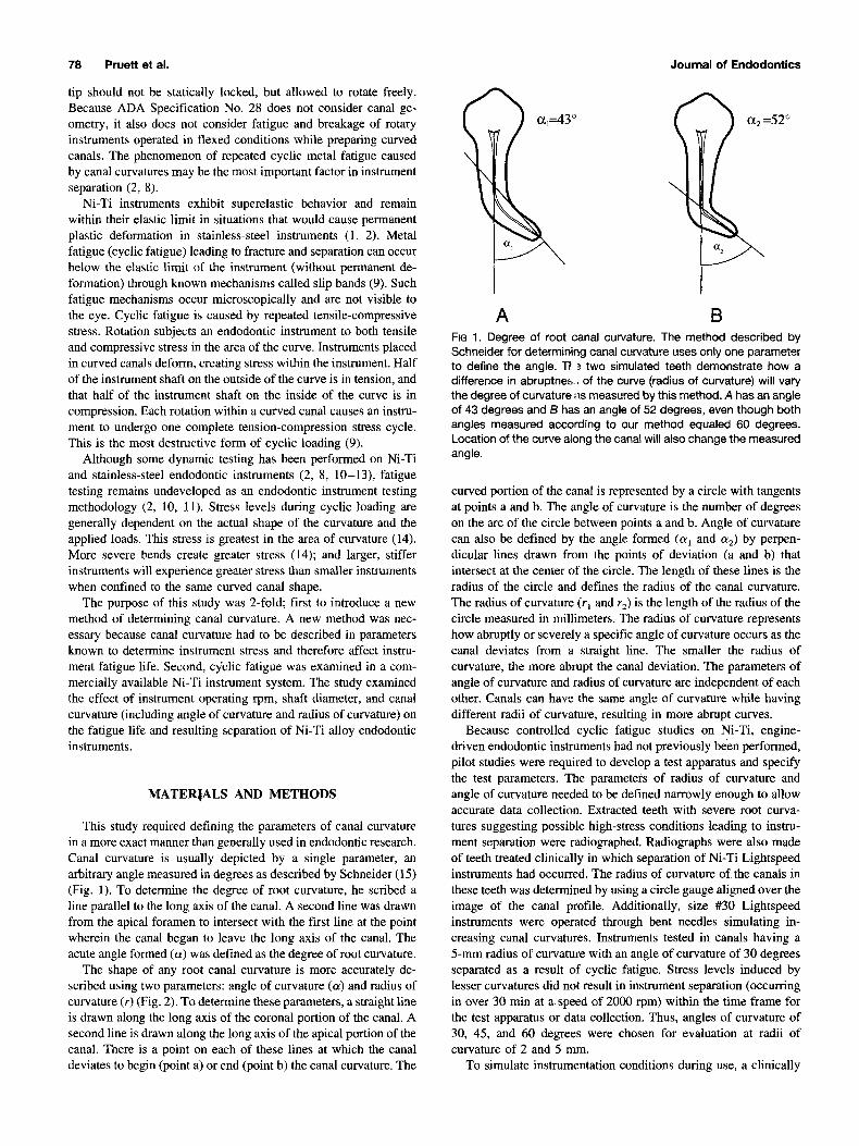
This study required defining the parameters of canal curvature in a more exact manner than generally used in endodontic research. Canal curvature is usually depicted by a single parameter, an arbitrary angle measured in degrees as described by Schneider (15) (Fig. 1). To determine the degree of root curvature, he scribed a line parallel to the long axis of the canal. A second line was drawn from the apical foramen to intersect with the first line at the point wherein the canal began to leave the long axis of the canal. The acute angle formed (a) was defined as the degree of root curvature.
The shape of any root canal curvature is more accurately de- scribed using two parameters: angle of curvature (a) and radius of curvature (r) (Fig. 2). To determine these parameters, a straight line is drawn along the long axis of the coronal portion of the canal. A second line is drawn along the long axis of the apical portion of the canal. There is a point on each of these lines at which the canal deviates to begin (point a) or end (point b) the canal curvature. The
Journal of EndodonUcs
30
A B FIG 1. Degree of root canal curvature. The method described by Schneider for determining canal curvature uses only one parameter to define the angle. Tt =, two simulated teeth demonstrate how a difference in abruptne~,, of the curve (radius of curvature) will vary the degree of curvature as measured by this method. A has an angle of 43 degrees and B has an angle of 52 degrees, even though both angles measured according to our method equaled 60 degrees. Location of the curve along the canal will also change the measured angle.
curved portion of the canal is represented by a circle with tangents at points a and b. The angle of curvature is the number of degrees on the arc of the circle between points a and b. Angle of curvature can also be defined by the angle formed (c~ 1 and c~2) by perpen- dicular lines drawn from the points of deviation (a and b) that intersect at the center of the circle. The length of these lines is the radius of the circle and defines the radius of the canal curvature. The radius of curvature (r I and r 2) is the length of the radius of the circle measured in millimeters. The radius of curvature represents how abruptly or severely a specific angle of curvature occurs as the canal deviates from a straight line. The smaller the radius of curvature, the more abrupt the canal deviation. The parameters of angle of curvature and radius of curvature are independent of each other. Canals can have the same angle of curvature while having different radii of curvature, resulting in more abrupt curves.
Because controlled cyclic fatigue studies on Ni-Ti, engine- driven endodontic instruments had not previously been performed, pilot studies were required to develop a test apparatus and specify the test parameters. The parameters of radius of curvature and angle of curvature needed to be defined narrowly enough to allow accurate data collection. Extracted teeth with severe root curva- tures suggesting possible high-stress conditions leading to instru- ment separation were radiographed. Radiographs were also made of teeth treated clinically in which separation of Ni-Ti Lightspeed instruments had occurred. The radius of curvature of the canals in these teeth was determined by using a circle gauge aligned over the image of the canal profile. Additionally, size #30 Lightspeed instruments were operated through bent needles simulating in- creasing canal curvatures. Instruments tested in canals having a 5-mm radius of curvature with an angle of curvature of 30 degrees separated as a result of cyclic fatigue. Stress levels induced by lesser curvatures did not result in instrument separation (occurring in over 30 min at a speed of 2000 rpm) within the time frame for the test apparatus or data collection. Thus, angles of curvature of 30, 45, and 60 degrees were chosen for evaluation at radii of curvature of 2 and 5 mm.
To simulate instrumentation conditions during use, a clinically
Vol. 23, No. 2, February 1997
o~=60 ° o~z =60 °
r2=2rnrn
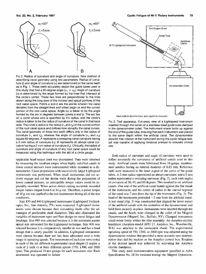
'A B FIG 2. Radius of curvature and angle of curvature. New method of describing canal geometry using two parameters. Radius of curva- ture (r) and angle of curvature (e) are determined on the same teeth as in Fig. 1. These teeth accurately depict the guide tubes used in this study that had a 60-degree angle ((~1 = (x2). Angle of curvature (c~) is determined by the angle formed by the lines that intersect at the circle's center. These two lines are perpendicular to the lines drawn along the long axes of the coronal and apical portions of the root canal space. Points a and b are the points wherein the canal deviates from the straight lines and either begin or end the curved portion of the root canal space. Angle ((~) is taken to be the angle formed by the arc in degrees between points a and b. The arc lies on a circle whose size is specified by it's radius, and the circle's radius is taken to be the radius of curvature of the canal in that local area. The circle's radius is the radius (rl and r2) of the curved portion of the root canal space and defines how abruptly the canal curves. The canal geometry of these two teeth differs only in the radius of curvature (r~ and r2 ) , whereas the angle of curvature ((x 1 and (x2) equals 60 degrees. A represents a sweeping canal curvature having a 5-mm radius of curvature (rl). B represents an abrupt canal cur- vature having a 2-mm radius of curvature (r2). Clinically, the radius of curvature and angle of curvature of any root canal space could be measured using this technique with the aid of a circle gauge.
applicable head torque load was determined. Data were obtained by measuring the resultant torque when highly calcified canals in lower central incisors were instrumented while mounted in a dy- namometer. Canal preparation with successively larger Lightspeed instruments was performed. When small instruments did not ac- tively engage and cut the dentin walls during the preparation of lower central incisors, no perceptible torque values could be re- peatably recorded. When active dentin cutting occurred, recorded torque values ranged from 6 to 14 g-cm. Therefore, a preset torque of 10 g-cm was applied to the test instruments during all of the test conditions.
Size #30 and #40 Lightspeed instruments (Lightspeed Technol- ogies, Inc., San Antonio, TX) were evaluated. Lightspeed instru- ments were chosen because their noncutting shafts offer the ad- vantages of predictable shaft diameters. This also eliminated the variables of instrument taper and flute design on metal fatigue and breakage. Size #40 was selected because it is the minimum master apical size advocated for the Lightspeed technique. Size #30 was selected because it is comparatively smaller in size and has a head design that is nearly parallel. In addition, Lightspeed instruments were chosen because their use has been advocated over a wide range of operating speeds. Ten instruments of each size were tested in each of the six different experimental canal shapes (3 angles c~ each of 2 radii r) at three different speeds (750, 1300, and 2000 rpm). This produced 18 test groups for each instrument size. Each instrument was operated to failure.
Cyclic Fatigue of Ni-Ti Rotary Instruments 79
Ni-Ti Lightspeed Instrument
Test Support Block
Guide Tube
Holddown .~" ,. Clamp
I I
Dynamometer Collet
LJ Input shaft to dynamometer, data aquisition computer
FIG 3. Test apparatus. Cut-away view of a Lightspeed instrument inserted through the lumen of a stainless-steel guide tube clamped in the dynamometer collet. The instrument shank butts up against the end of the guide tube, ensuring that each instrument was placed to the same depth within the artificial canal. The dynamometer allowed free rotation of the instrument during the cyclic fatigue test, yet was capable of applying torsional preload to simulate clinical use,
Both radius of curvature and angle of curvature were used to define accurately the curvatures of artificial canals used in this study. Artificial canals were fabricated from 18-gauge, stainless- steel needles having an internal diameter of 0.83 ram. Reference radii were measured to the inner aspect of the curve of the guide tubes. A 2-mm radius represented an abrupt curvature; and a 5 mm radius represented a sweeping curvature (Fig. 2), each with angles of curvature of 30, 45, and 60 degrees. This resulted in six artificial canals. One end of the artificial canal butted against the flat shank of the instrument, and the center of radius in the curved segment of the canal was 7 mm from the tip of the instrument (Fig. 3). The head of the instrument protruded - 2 mm from the artificial canal. A test stand (Fig. 3) was constructed that aligned the inner aspect of the artificial canals with the centerline of the dynamometer and held them securely in place. Instruments were inserted through the canals, and the heads were clamped in the collet of the Magtrol Dynamometer (Magtrol, Inc., Buffalo, NY). Clamped instruments could rotate freely within the tube assembly. An Aseptico electric handpiece (Aseptico model AEU-17, Aseptico, Inc., Woodinville, WA) was attached to the instrument shank. The experimental operating speed of 750, 1300, or 2000 rpm was adjusted using the dynamometer readout that provided a more accurate rpm determi- nation than did the readout on the Aseptico control box. Rotation at the desired speed was achieved by activating the Aseptico electric handpiece.
This study used instrumentation equipment specified in ADA Specification No. 28 for torsional testing: the Magtrol Dynamom-
80 Pruett et al.
eter. The dynamometer allows the torque applied to the instrument to be preset and measured while the instrument rotates. All instru- ments were operated with a head load of 10 g-cm torque. A software program (Sunset Resources, Inc., San Antonio, TX) was written for an IBM-compatible computer to permit data collection while the instrument was rotating. An 18-rain time limit for data collection was set as limited by the data collection program, but instrument separation always occurred within 5 min of beginning the test. Data collection from the dynamometer consisted of con- tinuous torque, and rpm readouts were comprised of 10 averaged readings/s. The time of instrument failure was determined when the torque values suddenly dropped, indicating instrument separa- tion. The number of cycles to failure was calculated from the rpm data by multiplying the rpm by the time to failure. Data analyzed were the number of cycles to failure for each instrument tested under the specified angle of curvature, radius of curvature, rpm, and instrument size conditions. Data were analyzed by analysis of variance (ANOVA), with the Neuman-Kuels procedure serving as the post-hoc test using a 95% confidence level.
Fractured instrument fragments were collected by group. Rep- resentative samples of the fracture surface from the various groups, and sizes were examined under scanning electron microscopic magnification with a JSM-840 scanning electron microscope (Japanese Electronic and Optical Ltd., Japan). Another group of instruments was partially cycled (75 to 80% to failure) using mean cycles-to-failure data from the matching experimental groups. These instruments were then mounted in both unflexed and flexed positions with the area of interest visible in side view, and exam- ined under scanning electron microscopy (SEM). For comparison, new same-sized instruments were mounted in the same manner and examined under SEM.
RESULTS
Operating rpm
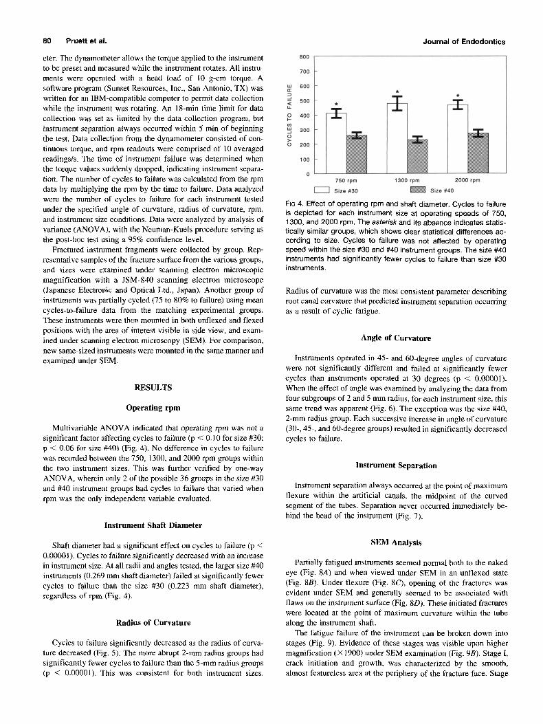
Multivariable ANOVA indicated that operating rpm was not a significant factor affecting cycles to failure (p < 0.10 for size #30; p < 0.06 for size #40) (Fig. 4). No difference in cycles to failure was recorded between the 750, 1300, and 2000 rpm groups within the two instrument sizes. This was further verified by one-way ANOVA, wherein only 2 of the possible 36 groups in the size #30 and #40 instrument groups had cycles to failure that varied when rpm was the only independent variable evaluated.
Instrument Shaft Diameter
Shaft diameter had a significant effect on cycles to failure (p < 0.00001). Cycles to failure significantly decreased with an increase in instrument size. At all radii and angles tested, the larger size #40 instruments (0.269 mm shaft diameter) failed at significantly fewer cycles to failure than the size #30 (0.223 nun shaft diameter), regardless of rpm (Fig. 4).
Radius of Curvature
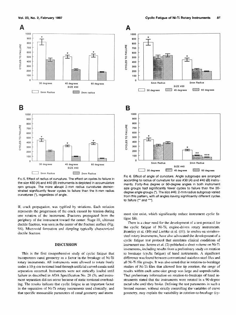
Cycles to failure significantly decreased as the radius of curva- ture decreased (Fig. 5). The more abrupt 2-ram radius groups had significantly fewer cycles to failure than the 5-mm radius groups (p < 0.00001). This was consistent for both instrument sizes.
Journal of Endodontics
800
700
600
500
400
300
200
100
0 750 rpm
I I size #30
l 1300 rpm
J 2000 rpm
Size #40
FiG 4. Effect of operating rpm and shaft diameter. Cycles to failure is depicted for each instrument size at operating speeds of 750, 1300, and 2000 rpm. The asterisk and its absence indicates statis- tically similar groups, which shows clear statistical differences ac- cording to size. Cycles to failure was not affected by operating speed within the size #30 and #40 instrument groups. The size #40 instruments had significantly fewer cycles to failure than size #30 instruments.
Radius of curvature was the most consistent parameter describing root canal curvature that predicted instrument separation occurring as a result of cyclic fatigue.
Angle of Curvature
Instruments operated in 45- and 60-degree angles of curvature were not significantly different and failed at significantly fewer cycles than instruments operated at 30 degrees (p < 0.00001). When the effect of angle was examined by analyzing the data from four subgroups of 2 and 5 mm radius, for each instrument size, this same trend was apparent (Fig. 6). The exception was the size #40, 2-mm radius group. Each successive increase in angle of curvature (30-, 45-, and 60-degree groups) resulted in significantly decreased cycles to failure.
Instrument Separation
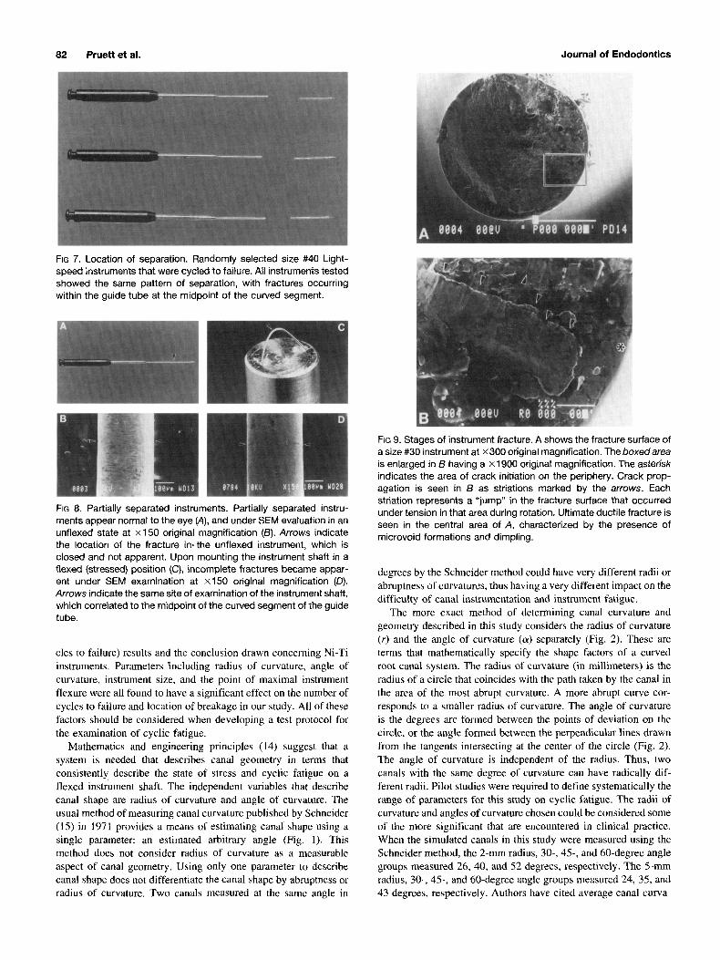
Instrument separation always occurred at the point of maximum flexure within the artificial canals, the midpoint of the curved segment of the tubes. Separation never occurred immediately be- hind the head of the instrument (Fig. 7).
SEM Analysis
Partially fatigued instruments seemed normal both to the naked eye (Fig. 8A) and when viewed under SEM in an unflexed state (Fig. 8B). Under flexure (Fig. 8C), opening of the fractures was evident under SEM and generally seemed to be associated with flaws on the instrument surface (Fig. 8D). These initiated fractures were located at the point of maximum curvature within the tube along the instrument shaft.
The fatigue failure of the instrument can be broken down into stages (Fig. 9). Evidence of these stages was visible upon higher magnification (×1900) under SEM examination (Fig. 9B). Stage I, crack initiation and growth, was characterized by the smooth, almost featureless area at the periphery of the fracture face. Stage
Vol. 23, No. 2, February 1997 Cyclic Fatigue of Ni-Ti Rotary Instruments 81
A 1000
900
800
700
600
500
400 O 300 O
200
100
0 30 degrees 45 degrees 60 degrees
SIZE #30
5mm Radius ~ 2ram radius
A 1000
gO0
8OO
~ 700
~ 600
O 500
~ 400
~ 300 O
2O0
100
0 5mm Radius 2ram Radius
SIZE #30
30 degrees ~ 45 degrees ~ 60 degrees
B 1000
900
800
700
600
500
400
300
200
100
0 30 degrees 45 degrees 60 degrees
SIZE #40
] 5rnm Radius ~ 2ram Radius
FIG 5. Effect of radius of curvature. The effect on cycles to failure in the size #30 (A) and #40 (B) instruments is depicted in accumulative rpm groups. The more abrupt 2-ram radius curvatures demon- strated significantly fewer cycles to failure than the 5-ram radius curvatures (*), regardless of angle.
II, crack propagation, was typified by striations. Each striation represents the progression of the crack caused by tension during one rotation of the instrument. Fractures propagated from the periphery of the instrument toward the center. Stage ]II, ultimate ductile fracture, was seen in the center of the fracture surface (Fig. 9A). Microvoid formation and dimpling typically characterized ductile fracture.
DISCUSSION
This is the first comprehensive study of cyclic fatigue that incorporates canal geometry as a factor in the breakage of Ni-Ti rotary instruments. All instruments were allowed to rotate freely under a 10 g-cm torsional load through artificial curved canals until separation occurred. Instruments were not statically loaded until failure as described in ADA Specification No. 28 (5), and instru- ment separation did not occur because of static torsional overload- ing. The results indicate that cyclic fatigue is an important factor in the separation of Ni-Ti rotary instruments used clinically, and that specific measurable parameters of canal geometry and instru-
B
=.
O I-
J o >. o
1000
900
800
700
600
500
400
300
200
100
0
i
5ram Radius 2ram Radius SIZE #40
30 degrees ~ 45 degreee ~ 60 degrees
FIG 6. Effect of angle of curvature. Angle subgroups are arranged according to radius of curvature for size #30 (A) and #40 (B) instru- ments. Forty-five degree or 60-degree angles in both instrument size groups had significantly fewer cycles to failure than the 30- degree angle groups (*). The size #40, 2-mm radius subgroup varied from this pattern, with all angles having significantly different cycles to failure (** and ***).
merit size exist, which significantly reduce instrument cyclic fa- tigue life.
There is a clear need for the development of a test protocol for the cyclic fatigue of Ni-Ti, engine-driven rotary instruments. Brantley et al. (10) and Luebke et al. (11), in studies on stainless- steel rotary instruments, have also advocated the development of a cyclic fatigue test protocol that simulates clinical conditions of instrument use. Serene et al. (2) published a short volume on Ni-Ti instruments, including results from a preliminary study on rotation to breakage (cyclic fatigue) of hand instruments. A significant difference was found between conventional stainless-steel files and all Ni-Ti file groups. It was also noted that in rotation-to-breakage studies of Ni-Ti files that allowed free tip rotation, the range of results within each same-size group was large and unpredictable. That preliminary information on rotation-to-breakage of hand in- struments stated that the instruments were rotated in a 90-degree metal tube until they broke. Defining the test parameters in such a limited manner, without strictly controlling the variables of curve geometry, may explain the variability in rotation-to-breakage (cy-
82 Pruett et al. Journal of Endodontics
FIG 7. Location of separation. Randomly selected size #40 Light- speed instruments that were cycled to failure. All instruments tested showed the same pattern of separation, with fractures occurring within the guide tube at the midpoint of the curved segment.
A
D
FIG 8. Partially separated instruments. Partially separated instru- ments appear normal to the eye (A), and under SEM evaluation in an unflexed state at x150 original magnification (B). Arrows indicate the location of the fracture in-the unflexed instrument, which is closed and not apparent. Upon mounting the instrument shaft in a flexed (stressed) position (C), incomplete fractures became appar- ent under SEM examination at x150 original magnification (D). Arrows indicate the same site of examination of the instrument shaft, which correlated to the midpoint of the curved segment of the guide tube.
cles to failure) results and the conclusion drawn concerning Ni-Ti instruments. Parameters including radius of curvature, angle of curvature, instrument size, and the point of maximal instrument flexure were all found to have a significant effect on the number of cycles to failure and location of breakage in our study. All of these factors should be considered when developing a test protocol for the examination of cyclic fatigue.
Mathematics and engineering principles (14) suggest that a system is needed that describes canal geometry in terms that consistently describe the state of stress and cyclic fatigue on a flexed instrument shaft. The independent variables that describe canal shape are radius of curvature and angle of curvature. The usual method of measuring canal curvature published by Schneider (15) in 1971 provides a means of estimating canal shape using a single parameter: an estimated arbitrary angle (Fig. 1). This method does not consider radius of curvature as a measurable aspect of canal geometry. Using only one parameter to describe canal shape does not differentiate the canal shape by abruptness or radius of curvature. Two canals measured at the same angle in
FIG 9. Stages of instrument fracture. A shows the fracture surface of a size #30 instrument at ×300 original magnification. The boxed area is enlarged in B having a x1900 original magnification. The asterisk indicates the area of crack initiation on the periphery. Crack prop- agation is seen in B as striations marked by the arrows. Each striation represents a "jump" in the fracture surface that occurred under tension in that area during rotation. Ultimate ductile fracture is seen in the central area of A, characterized by the presence of microvoid formations and dimpling.
degrees by the Schneider method could have very different radii or abruptness of curvatures, thus having a very different impact on the difficulty of canal instrumentation and instrument fatigue.
The more exact method of determining canal curvature and geometry described in this study considers the radius of curvature (r) and the angle of curvature (a) separately (Fig. 2). These are terms that mathematically specify the shape factors of a curved root canal system. The radius of curvature (in millimeters) is the radius of a circle that coincides with the path taken by the canal in the area of the most abrupt curvature. A more abrupt curve cor- responds to a smaller radius of curvature. The angle of curvature is the degrees arc formed between the points of deviation on the circle, or the angle formed between the perpendicular lines drawn from the tangents intersecting at the center of the circle (Fig. 2). The angle of curvature is independent of the radius. Thus, two canals with the same degree of curvature can have radically dif- ferent radii. Pilot studies were required to define systematically the range of parameters for this study on cyclic fatigue. The radii of curvature and angles of curvature chosen could be considered some of the more significant that are encountered in clinical practice. When the simulated canals in this study were measured using the Schneider method, the 2-mm radius, 30-, 45-, and 60-degree angle groups measured 26, 40, and 52 degrees, respectively. The 5-mm radius, 30-, 45-, and 60-degree angle groups measured 24, 35, and 43 degrees, respectively. Authors have cited average canal curva-

Vol. 23, No. 2, February 1997
tures for mandibular molars measured using the Schneider method between 20 to 30 degrees, with ranges between 6 to 48 degrees (16). Our 30-degree angle groups are well within the averages of canal measurement to be clinically relevant, whereas the angles larger than 30 degrees would be expected to be encountered less frequently.
Of the two canal-shape parameters, angle and radius of curva- ture, radius of curvature was the most significant factor of canal shape affecting the number of cycles to failure of Ni-Ti, engine- driven rotary instruments. Consistently, a decrease in the radius of curvature from 5 mm to 2 mm radius resulted in a significant decrease in the number of cycles to failure (Fig. 6). Explanation of the effect of radius is complex, but can be grossly simplified by stating that stress on the instrument is inversely proportional to the radius of curvature. Therefore, as the radius of curvature decreases, instrument stress and strain increases, and the fatigue life de- creases. To our knowledge, radius of curvature has not been previously considered as a separate independent variable in any instrumentation study.
Clinically, the sweeping curvature of the 5-mm radius groups, although challenging, is a much less difficult canal curvature to manage than the abrupt curvature represented by the 2-mm radius groups. Abrupt curvatures predominate in the apical third of the canal or in dilacerated roots. Both conditions are associated with an increased incidence of instrument separation. Degree of root cur- vature and instrument stiffness have been implicated in canal preparation errors, such as instrument breakage, ledging, block- ages, zipping, and perforation. However, radius of curvature with its resultant increased stress on endodontic instruments may also be a significant factor clinically contributing to instrument breakage and canal transportation. These areas should be studied more thoroughly, and the clinical effect of radius of curvature on instru- ment breakage and root canal preparation shape should be more clearly defined.
The 30-degree angle groups had significantly greater cycles to failure than the 45- and 60-degree angle groups, regardless of size (Fig. 6). This was an unexpected result when the engineering literature was reviewed, wherein the effect of angle alone seems negligible or uncertain. It was suspected that the 0.83 mm diameter stainless-steel tubes used in this study, although allowing free rotation of the instruments, did not sufficiently constrain the in- strument shafts in the 30-degree angle groups. This lack of con- straint, although not affecting the overall angle, did slightly in- crease the effective radius of curvature, allowing the instrument shaft to follow a larger radius path within the guide tube. Depend- ing on the angle of the tube and the instrument shaft diameter, the influence of angle of curvature was generally consistent in both the 2- and 5-ram groups. However, in the most highly stressed states studied (size #40 instruments in the 2-ram radius), increasing angle resulted in a significant decrease in cycles to failure between all three angle groups. Future studies should address this potential variable, more precisely controlling instrument constraint through- out the defined curvature.
The Lightspeed instrument is one of several Ni-Ti systems available to the practitioner. These instruments have a small cut- ting head, with a noncutting pilot tip. The shaft of the instrument is smooth, noncutting, and has a diameter that is smaller than the head. These features make Lightspeed instruments good experi- mental instruments in several respects. In particular, the design of the apparatus used for cyclic fatigue testing could be simplified, allowing the apparatus to create test stresses similar to typical
Cyclic Fatigue of Ni-Ti Rotary Instruments 83
fatigue-test equipment commonly used in other metallurgic appli- cations. The slender shaft allows quite severe bends without per- manent deformation, thus lending itself to a wider range of cur- vature conditions. A predictable metal shaft diameter eliminated having to account for additional variables, such as instrument flutes and taper. These characteristics, however, do not prevent the separation of Lightspeed instruments. All instruments tested in this study separated within a 5-min time limit.
Another advantage of using the Lightspeed instrument in this study was that operation has been advocated over a wide range of speeds. To investigate the effect of rpm on cyclic fatigue, testing was performed at 750, 1300, and 2000 rpm. The three rpm groups were not statistically different from one another (Fig. 4). Upon rotation, rising stress levels cause movement of dislocation defects and breaks atomic bonds within the crystalline matrix of the alloy, leading to crack initiation and propagation. The sharpness of the crack tip causes extreme stress concentration exceeding the strength of the metal at the crack tip in tension. The fracture propagates a short distance under tension, then ductile deformation blunts the crack tip, stopping the propagation. In the other half of the cycle, under compression, the alloy buckles microscopically and the crack resharpens (9). This minute propagation occurs on the order of 10-6 s or approximately at the speed of sound in metal (l 7), and the propagation event is completed much faster than the instrument is rotating. Thus, cyclic fatigue and the ultimate number of cycles to failure are unaffected by the rpm.
It is important to recognize that an instrument has a mean number of cycles to failure that is determined by specific param- eters of canal radius, canal angle, and instrument diameter. A higher rpm will consume the useful life of the instrument much faster than a lower rpm. Thus, a lower rpm would be beneficial and provide a greater clinical life, more slowly using the finite number of cycles to failure available. This is especially true when a Ni-Ti rotary instrument is used in severe curvature conditions suspected to induce stress fatigue. Although a wide range of operating speeds has been advocated for Ni-Ti, engine-driven systems, those rec- ommendations must take into account more than just cyclic fatigue as a cause of instrument separation. Nonetheless, the effect of rpm when studying the breakage of Ni-Ti instruments has not been previously examined and, in the present test conditions, rpm had no effect on cycles to failure.
The results of our investigation confirmed that instrument life span is inversely proportional to instrument size 0 2 , 13) and that metal fatigue is deeply implicated in file breakage (2, 8). Larger diameter instruments had a lower fatigue life, resulting in signif- icantly fewer cycles to failure than smaller diameter instruments (Fig. 5). The difference in average shaft diameters between these two instruments is only 0.046 ram. The larger diameter instrument was under more stress within the confines of a defined curvature. Therefore, considering cyclic fatigue as a contributor to instrument failure, larger instruments should not be considered safer or stron- ger in clinical practice. In fact, rotary Ni-Ti instruments with larger diameters would be expected to separate at fewer cycles than smaller diameter instruments.
The results of our study should not be interpreted as a fixed mean number of cycles to failure for either size #30 or #40 Lightspeed instrument during clinical use. Two important points of explanation are required. First, the point of maximal flexure in the curvature and, therefore, the stress on the instrument during this study was in a constant fixed location until separation occurred. Clinically, axial motion (in and out movements) during instrumen-
84 Pruett et al.
tation with Ni-Ti, engine-driven rotary instruments would be ex- pected, as concluded by Dederich et at. (12) examining stainless- steel instruments, to significantly extend instrument life. Ni-Ti instrument manufacturers suggest that these instruments be used with continuous axial motion in the canal. Lingering at a single depth in the canal would closely duplicate the test conditions of this study, significantly reducing the fatigue life of an instrument at a specific point along the instrument shaft. This mode of oper- ation is discouraged and should be avoided.
Second, engineering applications of Ni-Ti alloys have been extensively investigated (18-20), and the fatigue behavior of Ni-Ti alloys has been shown to be related to the static yield stress of the alloy. At low static stress, the alloy exhibits linear strain. Once the stress rises above the yield stress, small increases in the stress will give rise to large increases in strain that, unlike most metals, are reversible. This is the so-called superelastic characteristic. Ni-Ti fatigue tests conducted below the yield stress give results similar to ferrous alloys, such as stainless steel. Fatigue tests conducted above the yield stress in the superelastic range gives rise to distinct low-cycle fatigue behavior (18), which results in very rapid reduc- tions in fatigue life with increasing stress. This low-cycle fatigue has been shown to be more closely related to the amount of strain or flexure of the specimen than to the stress level and is largely a crack propagation process. This study was conducted in the range of superelastic rather than elastic state of deformation of the Ni-Ti instruments. Clinically, the fatigue life of an instrument can be related to the degree that it is flexed when placed in a curved canal, with greater flexures having a shorter expected life. The pilot studies used to determine the test parameters suggested that the state of superelastic deformation, when stresses rose above the yield stress, occurred between angles of 25 to 30 degrees when a size #30 instrument passed through a 5-ram radius curvature. At 30 degrees, low-cycle fatigue behavior resulted. At 25 degrees and below, the fatigue life was indefinitely long, suggesting elastic deformation of the alloy. Being tested in the superelastic state also helps explain the significant differences in the test groups when stresses were increased by decreasing the radius of curvature or increasing the angle of curvature; both resulted in increased strain. Most clinical applications of Ni-Ti instruments will at least peri- odically involve the superelastic flexure of these instruments, thus the need to understand this behavior. It is difficult to estimate the stress level in an instrument during use, but the degree to which it is strained or flexed can be monitored through knowledge of the canal curvature determine~t radiographically. Flexed conditions resulting in characteristics of relatively low stain and elastic de- formation would be expected to exhibit increased number of cycles to failure several orders of magnitude higher than those determined in this study (18).
All instruments tested separated at the point of maximum flex- ure within the curved segment of the tube, wherein the stress on the instrument was greatest (Fig. 8). The fractured surfaces seemed similar to those previously observed for fatigue testing (1 i). Un- flexed, partially fractured Ni-Ti instruments seemed normal with- out permanent plastic deformation. Under flexure, opening of the fractures was evident and generally seemed to be associated with flaws on the instrument surface directly in the area of maximum flexure. No instrument specimen separated at or just behind the head of the instrument in a successful test to its cyclic fatigue limit. This contradicts reports suggesting that the Canal Master instru- ment design is prone to separation just behind the head or in the apical third. Static torsional studies have shown that separation of
Journal of Endodontics
Ni-Ti Lightspeed instruments always occurred --2 mm behind the instrument head (7). That failure mode is limited to static testing. If instrument separation occurs behind the head of the instrument clinically, two explanations are possible. First, separation occurred as the result of locking or torsional overloading of the instrument head during rotation. Second, stress in a curved canal can cause fatigue failure directly behind the head. The head is inflexible and must pass through any curvature that the shaft experiences. Ex- cessive apically directed force on the instrument wilt cause the shaft to flex just behind the head. Both circumstances lead to stress concentration causing fatigue damage, accelerating separation caused by binding and fatigue. Separation of unbound instruments in the area of the most severe canal curvature should always be considered a result of cyclic fatigue with any instrument system.
Further study is required to improve the understanding of cri- teria that may be used to predict Ni-Ti instrument fatigue leading to separation. The fatigue of an instrument can be broken down into stages as evident on SEM examination (Fig. 9). Stage I, crack initiation, is characterized by the smooth, almost featureless area at the surface periphery. This area of fracture initiation maybe re- versible through proper heat treatment (9). Sterilization has been suggested to enhance the fatigue life of Ni-Ti files and reverse the stress-induced martensite transformation to the parent austenite phase (2). Furthermore, sterilization may reverse the crack initia- tion stage of fracture in Ni-Ti alloys, but this is an area for future investigation. Torsional loading during rotational use is another variable to consider that may dramatically influence the cyclic fatigue life of instruments. Engaged instruments that are actively cutting dentin would be expected to have different fatigue charac- teristics. The cyclic fatigue phenomenon may be further com- pounded by the addition of flutes to the shaft and by instrument taper. Flutes could act as stress concentrators on the instrument shaft, potentially resulting in more rapid crack initiation. Instru- ment taper enlarges the diameter of the instrument in the area of a coronal curvature, compared with the apical area, thus resulting in higher stress caused by a larger cross-sectional diameter. The effect of instrument flutes and cross-sectional diameters is an area of concern, particularly with the introduction of nonstandardized tapered Ni-Ti instruments. These areas should be addressed in the design of Ni-Ti, engine-driven rotary instruments and warrant further study.
Specific recommendations for preventing breakage of Light- speed instruments cannot be drawn from this study. However, because partially fatigued instruments did not demonstrate visible deformation, yet did exhibit crack formation, a general conclusion can be made. To prevent the breakage of Ni-Ti, engine-driven instruments secondary to cyclic fatigue, it seems that the best recommendation is to discard them after a specified use period as recommended for stainless-steel instruments. That use period would be expected to vary widely depending on instrument design, size, and stresses placed on it because of the manner of use, and the canal curvature prepared. In some severe angles having a small radius of curvature and a large angle of curvature, discarding an instrument after a single use may be the safest advice.
Canal curvature and angle have been implicated in instrument separation. Cyclic metal fatigue has been further implicated, as an important factor in instrument breakage. This study clearly showed that, in cyclic fatigue testing, cycles to failure is inversely propor- tional to instrument stress. Smaller radius of curvature and in- creased instrument diameter resulted in fewer cycles to failure caused by higher instrument stress. Cycles to failure was not affected by operating rpm, and the effect of angle alone on cycles
Vol. 23, No. 2, February 1997
to failure was unclear. New Ni-Ti instrument systems are currently being recommended for use in a continuously rotary manner, and a growing number of incidents of instrument separation are being informally discussed. Given the increased number of Ni-Ti end- odontic instrument systems on the market, these problems are likely to become more common. To date, there is no test protocol that sets minimum standards for cyclic fatigue of these instru- ments, nor are the operating parameters of importance yet fully understood. This study concludes with a call for a comprehensive cyclic fatigue test specification for all rotary endodontic instru- ments, including Ni-Ti instruments designed to be engine-driven and fully prepare curved canals. Furthermore, the parameters of angle of curvature and radius of curvature, and instrument cross- sectional core diameter must be included in any such specification. Without investigation of these parameters, recommendations for the safe use of Ni-Ti, engine-driven rotary instruments will remain speculative. The results also suggest that the effect of the radius of curvature as an independent variable should be considered in studies evaluating root canal instrumentation.
This study was supported in part by an Endodontic Student Award from the Research and Education Foundation of the American Association of Endodontists.
The opinions, assertions, materials, and methodologies herein are private ones of the authors and are not to be construed as official or reflecting the views of the American Association of Endodontists or the Foundation.
We gratefully acknowledge David S. Pittman of Sunset Resources, Inc. (San Antonio, TX) for modifying and writing the data collection program for the Magtrol Dynamometer. We express our gratitude to Drs. James A. Gilles, William A. Walker Ill, and Carlos E. del Rio for their advice during article preparation.
Drs. Pruett, Clement, and Carnes are affiliated with the Department of Endodontics/Dental School, University of Texas Health Science Center at San Antonio, San Antonio, TX. Address requests for reprints to Dr. David L. Carnes, Jr., Department of Endodontics/Dental School, University of Texas Health Science Center at San Antonio, 7703 Floyd Curl Drive, San Antonio, i X 78284-7898.
Cyclic Fatigue of Ni-Ti Rotary Instruments 85
References
1. Walia H, Brantley WA, Gerstein H. An initial investigation of the bending and torsional properties of nitinol root canal files. J Endodon 1988;14:346-51.
2. Serene TP, Adams JD, Saxena A. Nickel-titanium instruments: appli- cations in endodontics, St. Louis: Ishiyaku EuroAmerica, Inc., 1994.
3. GIosson CR, Hailer RH, Dove SB, del Rio CE. A comparison of root canal preparations using Ni-Ti hand, Ni-Ti engine driven, and K-Flex end- odontic instruments. J Endodon 1995;21:146-51.
4. Cohen S, Burns RC. Pathways of the pulp. 6th ed. St. Louis: Mosby- Year Book, Inc., 1994:206.
5. Council on Dental Materials and Devices. New ADA Specification No. 28 for endodontic files and reamers. J Am Dent Assoc 1976;93:813-8.
6. Camps J, Pertot WJ. Torsional and stiffness properties of Canal Master U stainless steel and nitinol instruments. J Endodon 1994;20:395-8.
7. Marsicovetere ES, Burgess JO, Clement D J, del Rio CE. Torsional testing of the lightspeed NiTi instrument system. J Endodon (in press).
8. Sotokawa T. An analysis of clinical breakage of root canal instruments. J Endodon 1988;14:75-82.
9. Dieter GE. Mechanical metallurgy. 3rd ed. New York: McGraw-Hill, 1986:119, 138, 185-8, 382-7, 394.
10. Brantley WA, Luebke H, Luebke FL, Mitchell JC. Performance of engine-driven rotary endodontic instruments with a superimposed bending deflection. V. Gates-Glidden and peeso drills. J Endodon 1994;20:241-5.
11. Luebke NH, Brantley WA, Sabri ZI, Luebke FL, Lausten LL. Physical dimensions, torsional performance, bending properties, and metallurgical characteristics of rotary endodontic instruments. VI. Canal Master drills. J Endodon 1995;21:259-63.
12. Dederich DN, Zakariasen KL. The effects of cyclical axial motion on rotary endodontic instrument fatigue. Oral Surg 1986;61:192- 6.
13. Haikel Y, Gasser P, Allemann C. Dynamic fracture of hybrid endodon- tic hand instruments compared with traditional files. J Endodon 1991 ;17:217-20.
14. Crandall SH, Dahl NC, Lardner TJ. An introduction to the mechanics of solids. 2rid ed. New York: McGraw-Hill, 1972:416-77.
15. Schneider SW. A comparison of canal preparations in straight and curved canals. Oral Surg 1971;32:271-5.
16. Cunningham CJ, Senia ES. A three-dimensional study of canal curvatures in the mesial roots of mandibular molars. J Endodon 1992;18:294-300.
17. Kanninen MF, Popelar CH. Advanced fracture mechanics. New York: Oxford University Press, 1985:22, 1980.
18. Melton KN, Mercier O. Fatigue of NiTi thermoelastic marfensites. Acta Met 1979;27:137-44.
19. Miyazaki S, Sugaya Y, Otsuka K. Effects of various factors on fatigue life of Ti-Ni alloys. MRS Int Mtg Aclv Mater 1989;9:251-6.
20. Tobushi H, Iwanaga H, Tanaka K, Hod T, Sawada T. Stress-strain- temperature relationships of TiNi shape memory alloy suitable for thermome- chanical cycling. JSME Int J Series I 1992;35:271-7.
You Might Be Interested
A case of fraud was recently uncovered in which an imposter had, over the past 25 years, managed to get a number of essays and letters to the editor published in respected journals. The JAMA unmasked the rascal because his "writing style had been recognized" (BMJ 311" 523, 1995).
Of course, there was another clue. The ficticious name signed to all those published letters over all those years was--you'll love this--T. H. Fiddleman.
Zachariah Yeomans