High-Temperature Corrosion-Fatigue Behavior of Ductile ... · due to the high cost of relative...
8
High-Temperature Corrosion-Fatigue Behavior of Ductile Cast Irons for Exhaust Manifolds Applications Shengmei Xiang 1,a* , Baohua Zhu 2,b , Stefan Jonsson 1,c 1 Mechanical Metallurgy, Materials Science and Engineering, Royal Institute of Technology, SE-100 44, Stockholm, Sweden 2 Scania CV AB, SE-151 87, Södertälje, Sweden a [email protected], b [email protected], c [email protected] Keywords: corrosion fatigue, ductile cast iron, high-temperature oxidation, controlled atmosphere Abstract. In the present study, low-cycle fatigue (LCF) tests and oxidation tests in controlled atmospheres are carried out at 800 ºC on two ductile cast irons SiMo51 and SiMo1000. The LCF tests are conducted in argon and synthetic exhaust gas, whereas oxidation tests are carried out in the latter atmosphere. S-N curves and weight-gain curves are presented. The crack growth mechanisms and oxidation mechanisms are investigated, as well as the synergetic effects. A surprising finding of increased fatigue resistance in oxidizing atmosphere is partly explained. 1. Introduction The exhaust gas temperature of heavy-duty diesel engines has increased substantially during the last decade due to improved fuel efficiency and increased specific power output [1]. The ongoing development of gas-driven Otto engines for heavy-duty vehicles and the use of bio-fuels will further increase the exhaust-gas temperature and render the gas composition more corrosive. Higher demands will thus be put on both heat- and corrosion resistance of the exhaust manifolds. Besides high-temperature and corrosive working condition, the material is also subject to thermal cycling caused by daily operation of the engine. Overall, the working environment for materials used in exhaust manifolds has been quickly becoming more and more demanding. The material used in current exhaust manifolds is a ferritic ductile cast iron called SiMo51, which is designed to serve under 800°C and is now working close to its upper temperature limit. One candidate material for higher temperature applications is the newly developed ferritic cast iron SiMo1000 [2]. Whereas due to the limitation and uncertainty of available test data, it is currently difficult to estimate its fatigue resistance under true service condition. Although F. Tholence has comprehensively studied varied oxidation behavior and kinetics of similar materials in different oxidative atmospheres [3,4], the result cannot be directly used as references since atmospheres that do not produce significant corrosion attack on unstressed samples may substantially increase the crack growth rate [5,6]. As a conclusion, S. Floreen [5] points out that ''conventional high-temperature corrosion tests may not be useful predicting service performance of stressed components.'' Therefore, other than separately evaluating the impact of fatigue and corrosion on the life time, it is more necessary to test the fatigue performance of the materials in real working atmospheres. Previous studies of these kinds of tests are mainly focused on Ni-based alloys which are typically used in aerospace applications [7-10] and are very limited in exhaust manifolds application due to the high cost of relative facilities. In this study, high-temperature low-cycle fatigue tests in synthetic exhaust gas are performed to simulate a more real working condition. To better understand the independent effect of fatigue and corrosion as well as their synergetic effect on the life time, LCF tests are conducted in both argon and synthetic exhaust gas, in addition, oxidation tests are performed in synthetic exhaust gas. Materials Science Forum Submitted: 2017-08-14 ISSN: 1662-9752, Vol. 925, pp 369-376 Revised: 2017-11-29 doi:10.4028/www.scientific.net/MSF.925.369 Accepted: 2018-01-29 © 2018 Trans Tech Publications Ltd, Switzerland Online: 2018-06-20 This is an open access article under the CC-BY 4.0 license (https://creativecommons.org/licenses/by/4.0/)
Transcript of High-Temperature Corrosion-Fatigue Behavior of Ductile ... · due to the high cost of relative...

High-Temperature Corrosion-Fatigue Behavior of Ductile Cast Irons for Exhaust Manifolds Applications
Shengmei Xiang1,a*, Baohua Zhu2,b, Stefan Jonsson1,c 1Mechanical Metallurgy, Materials Science and Engineering, Royal Institute of Technology,
SE-100 44, Stockholm, Sweden 2Scania CV AB, SE-151 87, Södertälje, Sweden
[email protected], [email protected], [email protected]
Keywords: corrosion fatigue, ductile cast iron, high-temperature oxidation, controlled atmosphere
Abstract. In the present study, low-cycle fatigue (LCF) tests and oxidation tests in controlled atmospheres are carried out at 800 ºC on two ductile cast irons SiMo51 and SiMo1000. The LCF tests are conducted in argon and synthetic exhaust gas, whereas oxidation tests are carried out in the latter atmosphere. S-N curves and weight-gain curves are presented. The crack growth mechanisms and oxidation mechanisms are investigated, as well as the synergetic effects. A surprising finding of increased fatigue resistance in oxidizing atmosphere is partly explained.
1. Introduction The exhaust gas temperature of heavy-duty diesel engines has increased substantially during the
last decade due to improved fuel efficiency and increased specific power output [1]. The ongoing development of gas-driven Otto engines for heavy-duty vehicles and the use of bio-fuels will further increase the exhaust-gas temperature and render the gas composition more corrosive. Higher demands will thus be put on both heat- and corrosion resistance of the exhaust manifolds. Besides high-temperature and corrosive working condition, the material is also subject to thermal cycling caused by daily operation of the engine. Overall, the working environment for materials used in exhaust manifolds has been quickly becoming more and more demanding. The material used in current exhaust manifolds is a ferritic ductile cast iron called SiMo51, which is designed to serve under 800°C and is now working close to its upper temperature limit. One candidate material for higher temperature applications is the newly developed ferritic cast iron SiMo1000 [2]. Whereas due to the limitation and uncertainty of available test data, it is currently difficult to estimate its fatigue resistance under true service condition.
Although F. Tholence has comprehensively studied varied oxidation behavior and kinetics of similar materials in different oxidative atmospheres [3,4], the result cannot be directly used as references since atmospheres that do not produce significant corrosion attack on unstressed samples may substantially increase the crack growth rate [5,6]. As a conclusion, S. Floreen [5] points out that ''conventional high-temperature corrosion tests may not be useful predicting service performance of stressed components.'' Therefore, other than separately evaluating the impact of fatigue and corrosion on the life time, it is more necessary to test the fatigue performance of the materials in real working atmospheres. Previous studies of these kinds of tests are mainly focused on Ni-based alloys which are typically used in aerospace applications [7-10] and are very limited in exhaust manifolds application due to the high cost of relative facilities. In this study, high-temperature low-cycle fatigue tests in synthetic exhaust gas are performed to simulate a more real working condition. To better understand the independent effect of fatigue and corrosion as well as their synergetic effect on the life time, LCF tests are conducted in both argon and synthetic exhaust gas, in addition, oxidation tests are performed in synthetic exhaust gas.
Materials Science Forum Submitted: 2017-08-14ISSN: 1662-9752, Vol. 925, pp 369-376 Revised: 2017-11-29doi:10.4028/www.scientific.net/MSF.925.369 Accepted: 2018-01-29© 2018 Trans Tech Publications Ltd, Switzerland Online: 2018-06-20
This is an open access article under the CC-BY 4.0 license (https://creativecommons.org/licenses/by/4.0/)
2. Method and Experimental Procedures 2.1. Materials
The tested SiMo51 alloy was supplied by Casting P.L.C and SiMo1000 by Georg Fischer Eisenguss GmbH. The chemical composition of the obtained ingots is shown in Table 1. Compared with SiMo51, SiMo1000 has high aluminum content, which is expected to give improved corrosion resistance, but it has also less silicon content which is expected to give the opposite effect. Hence, the relative oxidation resistance of the materials must be tested for each type of gas exposure.
Table 1. Chemical composition of the tested alloys, weight %, Fe balance [11].
C Si Mn Cr Ni Mo Al SiMo51 3.17 4.15 0.4 0.1 0.04 0.86 0.052 SiMo1000 3.57 2.72 0.25 0.07 0.84 0.81 3.08
The microstructure of SiMo51 shows a ferritic matrix with spheroidal graphite. In contrast, SiMo1000 also includes a substantial amount of compacted graphite. In both materials molybdenum carbides form in the ferritic grain boundaries.
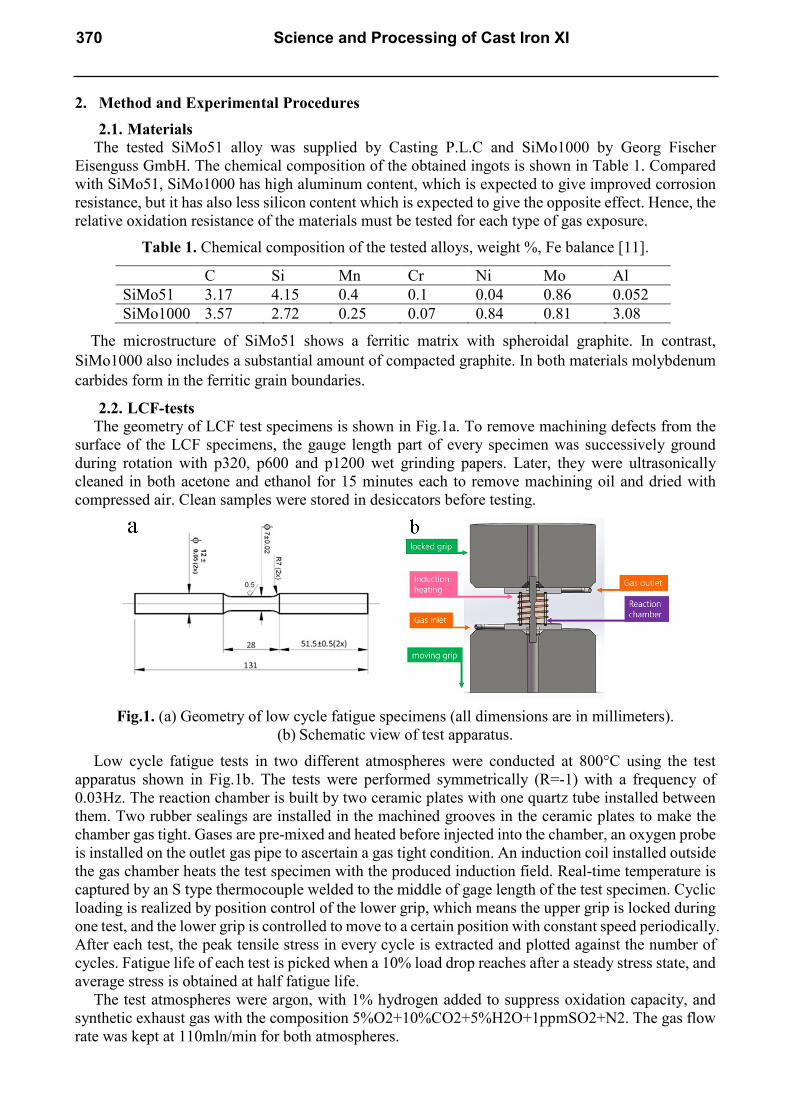
2.2. LCF-tests The geometry of LCF test specimens is shown in Fig.1a. To remove machining defects from the
surface of the LCF specimens, the gauge length part of every specimen was successively ground during rotation with p320, p600 and p1200 wet grinding papers. Later, they were ultrasonically cleaned in both acetone and ethanol for 15 minutes each to remove machining oil and dried with compressed air. Clean samples were stored in desiccators before testing.
Fig.1. (a) Geometry of low cycle fatigue specimens (all dimensions are in millimeters). (b) Schematic view of test apparatus.
Low cycle fatigue tests in two different atmospheres were conducted at 800°C using the test apparatus shown in Fig.1b. The tests were performed symmetrically (R=-1) with a frequency of 0.03Hz. The reaction chamber is built by two ceramic plates with one quartz tube installed between them. Two rubber sealings are installed in the machined grooves in the ceramic plates to make the chamber gas tight. Gases are pre-mixed and heated before injected into the chamber, an oxygen probe is installed on the outlet gas pipe to ascertain a gas tight condition. An induction coil installed outside the gas chamber heats the test specimen with the produced induction field. Real-time temperature is captured by an S type thermocouple welded to the middle of gage length of the test specimen. Cyclic loading is realized by position control of the lower grip, which means the upper grip is locked during one test, and the lower grip is controlled to move to a certain position with constant speed periodically. After each test, the peak tensile stress in every cycle is extracted and plotted against the number of cycles. Fatigue life of each test is picked when a 10% load drop reaches after a steady stress state, and average stress is obtained at half fatigue life.
The test atmospheres were argon, with 1% hydrogen added to suppress oxidation capacity, and synthetic exhaust gas with the composition 5%O2+10%CO2+5%H2O+1ppmSO2+N2. The gas flow rate was kept at 110mln/min for both atmospheres.
370 Science and Processing of Cast Iron XI

The gage length parts of the tested specimens were embedded in bakelite and ground until cross-sections of the cracks were received. Micro features and composition of the cross-sections were later captured by a Scanning Electron Microscope (SEM) equipped with an Energy Dispersive X-ray Detector (EDX).
2.3. Oxidation tests Eighteen cubic samples, approximately 25x20x5mm of each material were cut from the same
ingots as the LCF test specimens and used for isothermal oxidation tests in synthetic exhaust gas. To better compare the results from the oxidation tests with the oxidation during the LCF tests, the temperature, gas composition and gas flow rate were kept exactly the same as in the LCF tests. Furthermore, the test times (1.5 h, 4 h, 8 h, 16 h, 40 h, and 160 h) were chosen to be comparable with the five approximate LCF test times. Oxidation samples were inserted and removed from the furnace kept at 800°C.
3. Results and Discussion 3.1. LCF-test results
Using the data obtained from LCF-tests of the two materials in different atmospheres, stress vs. fatigue-life curves (S-N curves) were plotted. By comparing the curves of the same material in different atmospheres, the effect of corrosion on fatigue life was evaluated. By comparing the curves of different materials in the same atmosphere, the difference in material performance was evaluated.
Fig.2a shows the S-N curves of SiMo51 in different atmospheres. Contrary to our assumption, the material has higher fatigue strength in exhaust atmosphere than in argon. The fatigue strength at 15.000 cycles, for instance, is around 26 MPa in exhaust gas compared with about 19 MPa in argon. Thus, the fatigue strength is increased about 36% when exposed to an oxidizing atmosphere compared with an inert one. It is also noticed that when the material is tested at higher stress, the difference between the two curves disappears, meaning that the atmospheric effect is only important for longer exposure times.
Fig.2. S-N curves comparison of materials (a)SiMo51 and (b)SiMo1000.
The S-N curves for SiMo1000, Fig.2b, show the same behavior as for SiMo51. The fatigue strength at 15.000 cycles is increased from about 25 to 33 MPa, i.e. by 32% when changing the atmosphere from argon to exhaust gas whereas no effect is seen at high stresses, i.e. for low exposure times.
As one of the main objective of this project is to compare the performance of SiMo1000 with SiMo51, it’s of great interest to compare the S-N curves of these two materials in the same atmosphere, which is done in Fig.3a and b. As can be seen, in both atmospheres, the S-N curves of the two materials are almost parallel to each other. For SiMo51 and SiMo1000, the fatigue strength values at 15.000 cycles are about 26 and 33 MPa in exhaust atmosphere, and about 19 and 25 MPa in argon, respectively. Thus, SiMo1000 shows a fatigue strength about 27-31% higher than SiMo51.
Materials Science Forum Vol. 925 371

Fig.3. S-N curves comparison of materials in different atmospheres (a)argon and (b)exhaust.
To better understand the crack growth mechanisms in different atmospheres, characterization of the cross-section of tested LCF samples were conducted. Unfortunately, it was found that the obtained SiMo1000 material did not have a uniform graphite morphology. Instead, two zones with different graphite shapes were present, even in the same test sample, as shown in Fig.4. Naturally, it is believed that the zones with flake- and temper graphite will significantly reduce the fatigue life of this material.
Fig.4. Different graphite morphologies in SiMo1000.
As expected, the crack growth mechanism of SiMo1000 in argon atmosphere is dominated by linking of nearby graphite. In Fig.5a, it is seen how crack grows from one side of a flake to the other by delaminating the graphite and matrix material, then it goes a short distance in the matrix material to another graphite. In Fig.5b, although the graphite shape is completely different from what is shown in Fig.5a, the mechanism is the same.
Fig.5. Crack growth of SiMo1000 in argon atmosphere. In (a) flaky graphite dominate zone. In (b)
compacted graphite dominate zone. In exhaust atmosphere, different from what is observed on the samples tested in argon, a deep
decarburized zone is found under the sample surface. Closer inspection reveals that the crack is surrounded by oxide layers but the crack tip appears unaffected by the atmosphere. The crack growth shows the same mechanism as in argon, growing from flake to flake and no oxide layers are found around the crack tip as shown in Fig. 6.
372 Science and Processing of Cast Iron XI
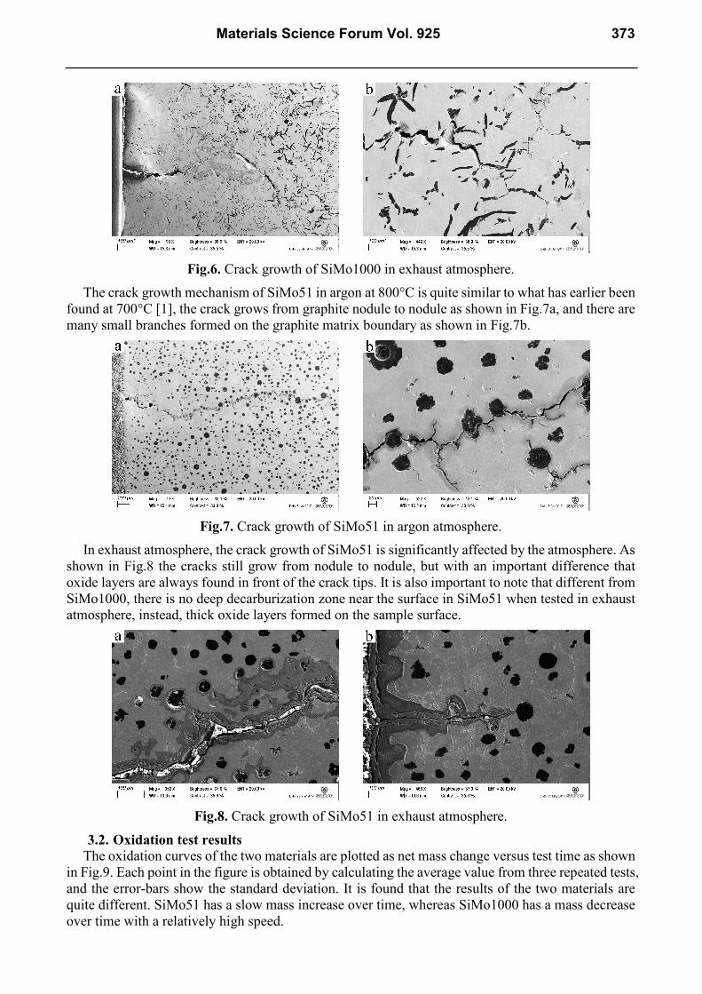
Fig.6. Crack growth of SiMo1000 in exhaust atmosphere.
The crack growth mechanism of SiMo51 in argon at 800°C is quite similar to what has earlier been found at 700°C [1], the crack grows from graphite nodule to nodule as shown in Fig.7a, and there are many small branches formed on the graphite matrix boundary as shown in Fig.7b.
Fig.7. Crack growth of SiMo51 in argon atmosphere.
In exhaust atmosphere, the crack growth of SiMo51 is significantly affected by the atmosphere. As shown in Fig.8 the cracks still grow from nodule to nodule, but with an important difference that oxide layers are always found in front of the crack tips. It is also important to note that different from SiMo1000, there is no deep decarburization zone near the surface in SiMo51 when tested in exhaust atmosphere, instead, thick oxide layers formed on the sample surface.
Fig.8. Crack growth of SiMo51 in exhaust atmosphere.
3.2. Oxidation test results The oxidation curves of the two materials are plotted as net mass change versus test time as shown
in Fig.9. Each point in the figure is obtained by calculating the average value from three repeated tests, and the error-bars show the standard deviation. It is found that the results of the two materials are quite different. SiMo51 has a slow mass increase over time, whereas SiMo1000 has a mass decrease over time with a relatively high speed.
Materials Science Forum Vol. 925 373

Fig.9. Oxidation test results of SiMo51 and SiMo1000 at 800°C in synthetic exhaust gas.
To find the reason for the negative weight change of SiMo1000, the cross-sections of the oxidation test samples were characterized. Fig.19a and b show the 16h and 160h samples, respectively. It can be noticed that the graphite shape differs a lot in the two samples although they come from the same plate. It is found that the decarburization depth increases from about 300 to about 1000 micrometers when the time is increased from 16 to 160h. Another important feature to be noticed is that the oxidized graphite nodules have not been replaced with oxides. Instead, empty pits are found.
Fig.10. Decarburization depth in SiMo1000 exposed to synthetic exhaust gas
at 800°C for (a) 16h and (b) 160h. EDX characterization shows the presence of thin aluminum oxides in the pits, Fig. 11. The
compact aluminum oxide protects the material from being further corroded. Thus, the negative weight change of SiMo1000 can be explained by the weight loss of graphite being much higher than the weight gain by forming aluminum oxides.
Fig.11. EDX mapping of the decarburization layer in the SiMo1000 sample exposed to synthetic
exhaust gas at 800°C for 160h. Different from the oxidation behavior of SiMo1000, no deep decarburization zone is found in
SiMo51 as can be seen from Fig.12a showing the cross-section of the 160h test sample in exhaust
374 Science and Processing of Cast Iron XI

atmosphere. The difference is due to different graphite morphology [12], decarburization is much more severe in lamellar-graphite iron than in spheroidal type. In Fig.12b, at higher magnification, it is found that the surface graphite is oxidized first, releasing the surface carbon from the material. Then, oxides fill the empty pits over time. As the oxide layer grows, it will attach to another graphite nodule deeper in the matrix and the process is repeated. This mechanism is known as oxide intrusion [11]. Comparing with the results in section 4.1, Fig. 8, the oxidation experiments supports the observation that the oxide layer first grows from nodule to nodule and the fatigue crack then grows in the formed oxides. Because of the formed crack, the growth of deeper lying oxides is increased. Hence, there is a synergy between oxidation and mechanical fatigue. Surprisingly, the oxidation does not reduce the fatigue life of SiMo51. Instead, it increases it. One possible explanation is that since the LCF tests were performed symmetrically (R=-1) by position control of the lower grip while locking the upper grip during one test, the formation of oxides increased the volume of surface material, which resulted in compressive stresses in the sample. The compressive stresses slowed down the fatigue crack initiation and thus improved the fatigue life of the sample. This can also explain why the environmental effect is only found when exposure time are long enough. However, this hypothesis needs to be further confirmed by running LCF test with varied R values.
The increased fatigue life of SiMo1000 in exhaust gases, compared with argon is more difficult to explain as the growth mechanism is graphite-to-graphite linking in both cases without formation of deeper oxides. It appears difficult to believe that the deep decarburizing zone formed in exhaust gas should improve the fatigue strength. However, replacing graphite with voids reduces the stiffness of the material, possibly reducing the fatigue crack initiation. Admittedly, further examinations are necessary to explain the observed results.
Fig.12. Cross-section of SiMo51, exposed to synthetic exhaust gas at 800°C for 160h,
shown in two magnifications.
4. Summary In this paper, LCF-tests in argon and synthetic exhaust gas were conducted as well as isothermal oxidation tests in synthetic exhaust gas for SiMo51 and SiMo1000. Surprisingly, the fatigue strengths of both materials are better in the corrosive gas compared with the inert one. At 15.000 cycles the fatigue strength is increased by 32 and 36%, respectively. On the other hand, at short fatigue lives, i.e. high stresses, there are no differences between the fatigue strengths in different atmospheres. In both atmospheres, SiMo1000 generally has about 27-31% higher fatigue life at 15.000 cycles.
In argon, the crack tip advances by graphite-to-graphite linking in both materials. For SiMo51, the linking is from nodule-to-nodule with many crack branches and in SiMo1000, it is from flake-to-flake. Admittedly, the investigated SiMo1000 had non-uniform graphite morphology.
In synthetic exhaust gas, SiMo51 is oxidized by oxide intrusion. Graphite nodules, deeper and deeper in the material, are successively replaced by iron oxides. Fatigue cracks advances by growth in oxides in front of the crack tip. SiMo1000 forms a deep surface decarburized zone where the oxidized graphite is not replaced by oxides. Instead a network of voids is formed covered with a thin shell of
Materials Science Forum Vol. 925 375

aluminum oxides. No deep oxides form and fatigue cracks advance by graphite-to-graphite linking, as in argon.
Oxidation tests in synthetic exhaust gas show a slow weight gain of SiMo51 with time mainly because of oxidation. SiMo1000, on the other hand, shows a rapid weight decrease because of extensive surface decarburization accompanied by the formation of a thin aluminum oxides shell on the surfaces of the formed voids.
The increased fatigue life of both materials in the synthetic exhaust gas appears to be attributed to two different mechanisms. For SiMo51 the fatigue crack growth is slowed down because of compressive stresses formed by growing oxides. For SiMo1000 the slower fatigue crack growth is caused by reduced stiffness due to surface decarburization, lowering the surface stress amplitude.
Acknowledgements This work was performed at KTH, financed by Scania CV AB and CSC (China Scholarship
Council). KIMAB is acknowledged for conducting the oxidation tests. The authors are grateful to the instructions and support from Madeleine Ekström Scania CV AB and Joakim Lindblom. The authors would also like to thank Georg Fischer Eisenguss GmbH for providing SiMo1000 material and Scania CV AB for preparing the samples.
References
[1] M. Ekström, Oxidation and Corrosion Fatigue Aspects of Cast Exhaust Manifolds, Doctoral thesis, Stockholm, 2015, http://urn.kb.se/resolve?urn=urn:nbn:se:kth:diva-166274 .
[2] S. Kleiner, K. Track, SiMo1000—Ein aluminiumlegiertes Gusseisen für Hochtemperaturanwendungen, Giesserei, 97(10) (2010) 28-34.
[3] F. Tholence, Mats Norell, High temperature corrosion of cast alloys in exhaust environments I-ductile cast irons, Oxid. Met. 69 (2008) 13-36.
[4] F. Tholence, Mats Norell, High-Temperature Corrosion of Cast Irons and Cast Steels in Dry Air, Mater. sci. forum. 369-372 (2001) 197-204.
[5] S. Floreen, R. H. Kane, Effects of environment on high-temperature fatigue crack growth in a superalloy, Metall. Mater. Trans. A 10 (1979) 1745-1751.
[6] Andre Pineau, Stephen D. Antolovich, High temperature fatigue of nickel-base superalloys–a review with special emphasis on deformation modes and oxidation, Eng. Fail. Anal. 16 (2009) 2668-2697.
[7] S. Floreen, R. H. Kane, Elevated temperature fatigue crack growth in incoloy alloy 800 in sulfidizing environments, Metall. Trans. A 13 (1982) 145-152.
[8] S. Floreen, C. J. White, Elevated temperature crack growth in nickel-base alloys in carburizing environments, Metall. Mater. Trans. A 12 (1981) 1973-1979.
[9] S. Floreen, R. H. Kane, The sulfidation attack of a nickel-base alloy at intermediate temperatures, Metall. Mater. Trans. A 15 (1984) 5-10.
[10] R. Mollins, G. Hochstetter, J.C. Chassaigne, E. Andrieu, Oxidation effects on the fatigue crack growth behaviour of alloy 718 at high temperature, Acta Mater 45 (issue 2) (1997) 663-674.
[11] V. Norman, P. Skoglund, D. Leidermark, J. Moverare, Damage mechanisms in silicon-molybdenum cast irons subjected to thermo-mechanical fatigue, Int J Fatigue 99 (2017) 258-265.
[12] Y. Yamaguchi, S. Kiguchi, H. Sumimoto, Dr. K. Nakamura, Effect of graphite morphology on decarburized cast iron, Int. J. Cast Metal. Res. 16 (issue 1-3) (2003) 137-142.
376 Science and Processing of Cast Iron XI