Development of Ultrasonic Fatigue for Rapid, High ... · PDF filedevelopment of ultrasonic...
10
DEVELOPMENT OF ULTRASONIC FATIGUE FOR RAPID, HIGH TEMPERATURE FATIGUE STUDIES IN TURBINE ENGINE MATERIALS A. Shyam 1 , C. J. Torbet 1 , S. K. Jha 2 , J. M. Larsen 3 , M. J. Caton 3 , C. J. Szczepanski 1 , T. M. Pollock 1 , J. W. Jones 1 1 Materials Science and Engineering, University of Michigan, Ann Arbor, MI-48109 USA 2 Universal Technology Corporation, Dayton, Ohio 45432 USA 3 Materials and Manufacturing Directorate, AFRL/MLLMN Wright Patterson AFB, Dayton, OH-45433 USA Keywords: Ultrasonic Fatigue, Crack Initiation, Fatigue Micromechanisms, Laser Machining. Abstract A system for ultrasonic fatigue testing at temperatures as high as 700 C and at positive mean stresses has been developed. Its use is demonstrated by examining the fatigue behavior in the lifetime range of 10 5 to 10 9 cycles for the nickel-base superalloy Rene' 88 DT at 20 and 593 C for a load-ratio of 0.05. Crack initiation occurred from large grains and from inclusions, consistent with crack initiation behavior at conventional test frequencies. Surface condition influenced fatigue behavior at ambient temperature, where electropolished specimens had considerably shorter lives than as-machined specimens. At 593 C, however, no effect of surface condition on fatigue lifetime was observed since subsurface initiation occurred for both electropolished and as- machined specimens. Fatigue life, at a given stress appears to be shorter when testing at ultrasonic frequencies compared to the behavior observed at conventional frequencies and the exact causes for this remain to be determined. It is also demonstrated that fatigue cracks could be initiated and grown from micronotches with dimensions on the order of grain size. Introduction In recent years there has been a growing interest in accelerating the development and use of new materials in critical aerospace systems. An important part of this effort involves substantial improvement of fatigue life prediction capabilities. However, the prediction of residual fatigue life in critical turbine components is complicated by the variability in measured fatigue behavior of the complex structural alloys required for engines and airframes. This variability, commonly manifested as scatter in experimentally determined fatigue lifetimes, is often significantly greater than that for other mechanical properties such as yield strength, ductility and ultimate tensile strength. [1,2]. In general, scatter in fatigue life increases at low stress amplitudes, where crack initiation and short crack propagation control lifetime [3-5] and where long crack growth behavior is less important [6,7]. In this regime, the sensitivity to microstructural variability not only complicates life prediction, but presents a challenge for design of new alloys and microstructures for optimum resistance to fatigue failure. Here microstructure is defined broadly to include porosity, inclusions, constituent particles and non-homogeneous distributions of size and orientation of critical microstructure features, as well as the more commonly identified parameters, such as grain size, phase volume fraction and crystallographic texture. Numerous studies have been conducted in the last fifty years to identify the physical mechanisms of fatigue in structural alloys and to better understand how microstructure affects mean fatigue properties. Of particular interest are the processes that control fatigue crack initiation and early growth and several excellent reviews can be found in the literature [8-12]. Traditional approaches to life prediction treat fatigue life variability as a statistical problem where fatigue life data are acquired, distribution functions for the observed lifetimes are identified and probabilities of survival for given operating conditions and desired lifetimes are subsequently assigned. Most fatigue life data are assumed to follow standard statistical distributions [13-18]. In some cases statistical treatments allow the differentiation of key microstructural parameters, such as grain size, pore size and inclusion size that are presumed to control crack initiation or short crack propagation behavior [13,14,17,18]. However, this approach is limited, among other factors, by the difficulty of coupling microstructure variability and fatigue life variability. Because of the complexity of fatigue crack initiation processes and the increased need to predict fatigue lives well beyond the practical measurement range, probabilistic approaches have been examined with growing interest. Probabilistic approaches extend beyond statistical approaches in that micromechanisms for crack initiation and/or early crack propagation are identified by experiment or assumed and incorporated into probabilistic life prediction models. The variability in microstructural parameters is then determined experimentally or approximated by Monte Carlo or more advanced computational methods. While significant progress has been made, the modeling of fatigue behavior and, in particular, the development of accurate analytical approaches to total lifetime prediction have not achieved the level of sophistication that is enjoyed in modeling deformation and fracture behavior. A central challenge is the stochastic nature of fatigue where so-called “single events”, dependent on microstructural variability, can determine lifetime. Furthermore, it has been experimentally difficult to examine in a statistically significant manner, fatigue behavior at low to intermediate stresses where long fatigue lives are observed. Ultrasonic fatigue is a promising tool to interrogate some of the issues mentioned above. Ultrasonic Fatigue The ultrasonic fatigue technique offers an attractive approach to study the crack initiation and early crack propagation behavior because cyclic frequencies can be as much as three orders of magnitude greater than conventional testing. This enables acquisition of significant data over a wide range of accumulated cycles and lifetimes that is simply not possible to achieve with testing at conventional frequencies. In ultrasonic fatigue a sound wave is injected into the specimen under appropriate conditions to cause the specimen to vibrate in mechanical resonance. The strain 259 Superalloys 2004 Edited by K.A. Green, T.M. Pollock, H. Harada, TMS (The Minerals, Metals & Materials Society), 2004 T.E. Howson, R.C. Reed, J.J. Schirra, and S, Walston
Transcript of Development of Ultrasonic Fatigue for Rapid, High ... · PDF filedevelopment of ultrasonic...
DEVELOPMENT OF ULTRASONIC FATIGUE FOR RAPID, HIGH TEMPERATURE FATIGUE
STUDIES IN TURBINE ENGINE MATERIALS
A. Shyam1, C. J. Torbet1, S. K. Jha2, J. M. Larsen3, M. J. Caton3, C. J. Szczepanski1, T. M. Pollock1, J. W. Jones1
1Materials Science and Engineering, University of Michigan, Ann Arbor, MI-48109 USA 2Universal Technology Corporation, Dayton, Ohio 45432 USA
3Materials and Manufacturing Directorate, AFRL/MLLMN Wright Patterson AFB, Dayton, OH-45433 USA
Keywords: Ultrasonic Fatigue, Crack Initiation, Fatigue Micromechanisms, Laser Machining.
Abstract
A system for ultrasonic fatigue testing at temperatures as high as
700 C and at positive mean stresses has been developed. Its use is
demonstrated by examining the fatigue behavior in the lifetime
range of 105 to 109 cycles for the nickel-base superalloy Rene' 88
DT at 20 and 593 C for a load-ratio of 0.05. Crack initiation
occurred from large grains and from inclusions, consistent with
crack initiation behavior at conventional test frequencies. Surface
condition influenced fatigue behavior at ambient temperature,
where electropolished specimens had considerably shorter lives
than as-machined specimens. At 593 C, however, no effect of
surface condition on fatigue lifetime was observed since
subsurface initiation occurred for both electropolished and as-
machined specimens. Fatigue life, at a given stress appears to be
shorter when testing at ultrasonic frequencies compared to the
behavior observed at conventional frequencies and the exact
causes for this remain to be determined. It is also demonstrated
that fatigue cracks could be initiated and grown from
micronotches with dimensions on the order of grain size.
Introduction
In recent years there has been a growing interest in
accelerating the development and use of new materials in critical
aerospace systems. An important part of this effort involves
substantial improvement of fatigue life prediction capabilities.
However, the prediction of residual fatigue life in critical turbine
components is complicated by the variability in measured fatigue
behavior of the complex structural alloys required for engines and
airframes. This variability, commonly manifested as scatter in
experimentally determined fatigue lifetimes, is often significantly
greater than that for other mechanical properties such as yield
strength, ductility and ultimate tensile strength. [1,2]. In general,
scatter in fatigue life increases at low stress amplitudes, where
crack initiation and short crack propagation control lifetime [3-5]
and where long crack growth behavior is less important [6,7]. In
this regime, the sensitivity to microstructural variability not only
complicates life prediction, but presents a challenge for design of
new alloys and microstructures for optimum resistance to fatigue
failure. Here microstructure is defined broadly to include porosity,
inclusions, constituent particles and non-homogeneous
distributions of size and orientation of critical microstructure
features, as well as the more commonly identified parameters,
such as grain size, phase volume fraction and crystallographic
texture. Numerous studies have been conducted in the last fifty
years to identify the physical mechanisms of fatigue in structural
alloys and to better understand how microstructure affects mean
fatigue properties. Of particular interest are the processes that
control fatigue crack initiation and early growth and several
excellent reviews can be found in the literature [8-12].
Traditional approaches to life prediction treat fatigue life
variability as a statistical problem where fatigue life data are
acquired, distribution functions for the observed lifetimes are
identified and probabilities of survival for given operating
conditions and desired lifetimes are subsequently assigned. Most
fatigue life data are assumed to follow standard statistical
distributions [13-18]. In some cases statistical treatments allow
the differentiation of key microstructural parameters, such as
grain size, pore size and inclusion size that are presumed to
control crack initiation or short crack propagation behavior
[13,14,17,18]. However, this approach is limited, among other
factors, by the difficulty of coupling microstructure variability and
fatigue life variability.
Because of the complexity of fatigue crack initiation
processes and the increased need to predict fatigue lives well
beyond the practical measurement range, probabilistic approaches
have been examined with growing interest. Probabilistic
approaches extend beyond statistical approaches in that
micromechanisms for crack initiation and/or early crack
propagation are identified by experiment or assumed and
incorporated into probabilistic life prediction models. The
variability in microstructural parameters is then determined
experimentally or approximated by Monte Carlo or more
advanced computational methods.
While significant progress has been made, the modeling of
fatigue behavior and, in particular, the development of accurate
analytical approaches to total lifetime prediction have not
achieved the level of sophistication that is enjoyed in modeling
deformation and fracture behavior. A central challenge is the
stochastic nature of fatigue where so-called “single events”,
dependent on microstructural variability, can determine lifetime.
Furthermore, it has been experimentally difficult to examine in a
statistically significant manner, fatigue behavior at low to
intermediate stresses where long fatigue lives are observed.
Ultrasonic fatigue is a promising tool to interrogate some of the
issues mentioned above.
Ultrasonic Fatigue
The ultrasonic fatigue technique offers an attractive approach
to study the crack initiation and early crack propagation behavior
because cyclic frequencies can be as much as three orders of
magnitude greater than conventional testing. This enables
acquisition of significant data over a wide range of accumulated
cycles and lifetimes that is simply not possible to achieve with
testing at conventional frequencies. In ultrasonic fatigue a sound
wave is injected into the specimen under appropriate conditions to
cause the specimen to vibrate in mechanical resonance. The strain
259
Superalloys 2004Edited by K.A. Green, T.M. Pollock, H. Harada,
TMS (The Minerals, Metals & Materials Society), 2004T.E. Howson, R.C. Reed, J.J. Schirra, and S, Walston
imposed on the gage section can be monitored and controlled by
adjusting the amplitude of the input signal. With this approach, a
specimen is tested in mechanical resonance at frequencies of
approximately 20 kHz. The advantages of this in terms of the
ability to accelerate tests are obvious. For example, at 20 kHz,
applying 108 cycles requires approximately 3 hours and applying
109 cycles can be completed typically within 1 day. Therefore, a
significant amount of data can be established in a very short
period of time in the intermediate fatigue life regime. Thus, the
fatigue behavior at cycles more representative of the expected
service life can be determined experimentally, rather than
estimated from extrapolations.
The technique was first explored in the 1950s and the early
work through 1980 was reviewed by Willertz in 1980 [19]. More
recently, Mayer has offered a comprehensive review of
improvements in the past ten years, especially regarding the use of
ultrasonic fatigue for fatigue crack growth threshold studies [20].
In the United States, early work was begun by Tien and co-
workers in the late 1970s and early 1980s [21,22] but in recent
years, research effort has been concentrated primarily in Japan
and Europe, where the technique is enjoying considerable use
there as a tool for very long fatigue life prediction [23,24]. The
growing interest in ultrasonic fatigue is driven in part by the
increased need to predict lifetimes in aging structures and is made
possible by dramatic improvements in the accuracy of control
instrumentation for ultrasonic fatigue.
Numerous studies have been conducted showing that the
fatigue behavior of many important structural materials systems,
including aluminum, titanium and nickel based alloys can be
determined effectively by ultrasonic fatigue methods [19,20,23].
Importantly, frequency effects may not be significant for many
structural materials unless environmental attack is occurring
simultaneously. The objective of the work described in this paper
is to examine the potential use of ultrasonic fatigue in the study of
the relationship between microstructural variability and fatigue
life in structural turbine alloys, especially at long fatigue lives.
We describe an ultrasonic fatigue test system capable of operation
at temperatures as high as 600oC under variable mean stress
loading. Initial results of high temperature ultrasonic fatigue
studies are presented for the disk alloy Rene' 88 DT [25].
Experimental Procedure
The ultrasonic fatigue test system that has been developed
for fatigue studies on superalloys and other high temperature
materials is shown in Figure 1. A high accuracy ultrasonic
amplifier drives the piezoelectric transducer. Feedback from an
inductive vibration gage is used to control vibration amplitude and
frequency to within 1%. Cycles can be applied in pulses as short
as 25 ms (500 cycles) to prevent specimen heating during cycling
at room temperature. Specimens with diameters of 5-6 mm and
overall dimensions similar to specimens used in conventional
fatigue testing are typically used. Other specimen shapes, such as
hourglass specimens are also used. The transducer is isolated
from the mean load by a specially constructed cage and the
transducer, load train and specimen are designed such that the
specimen is in resonance at or near 20 kHz, with displacement
anti-nodes occurring at the specimen ends. The mean load is
applied at a flange which is located at an exact displacement node
and therefore, does not affect the ultrasonic load train. Specimen
heating is accomplished by induction heating and Figure 2 shows
the induction coil arrangement around a standard cylindrical
ultrasonic fatigue specimen of Rene' 88 DT. The temperature at
the center of the specimen is measured and controlled with a non-
contact infra-red pyrometer. The induction coil design is
optimized to provide uniform heating along the entire length of
the gage section. Induction heating in this manner produces a
temperature variation of + 3oC in the gage section of the
cylindrical specimen.
(a)
(b)
Figure 1: The ultrasonic fatigue testing system capable of testing
with superimposed mean stresses at elevated temperature (a) the
entire system with the controls and (b) the ultrasonic fatigue load
train.
Fatigue tests were conducted at a load-ratio of 0.05 and
temperatures of 20oC and 593oC. The desired mean stress was
260
applied using a servohydraulic fatigue testing system and the
alternating stress was accomplished with ultrasonic loading.
Fatigue cycles were applied in pulses of 500 ms followed by a
pause of 900 ms at 20oC. This was done to prevent the specimen
from heating as a result of high frequency cycling. At 593oC,
however, ultrasonic loading was continuous since the heat
generated was compensated by the temperature control system.
There was no statistically significant influence of pulsed loading
at elevated temperature since both pulsed and continuously loaded
specimens yielded similar lifetimes under a given condition.
Closed loop control of specimen displacement is achieved
during fatigue. This is accomplished by measuring the
displacement amplitude of the load train at the specimen using an
inductance transducer. This feedback signal is then used to control
specimen strain. The feedback signal is calibrated to specimen
strains using the output of strain gages attached to the gage
section. A high temperature strain gage was used to measure the
response of the system as it is heated from 20 to 593oC under
displacement control. It was found the strain in the specimen
center increased by approximately 6% as a result of heating to
593oC. This factor of 1.06 (which was verified by modeling
temperature effects on resonance) was used to calibrate for
imposed strains at 593oC by making strain measurements at room
temperature.
At higher test stresses, the strain gaging technique requires
extrapolation of the feedback signal/specimen strain data, rather
than interpolation. Consequently, the instrument is now equipped
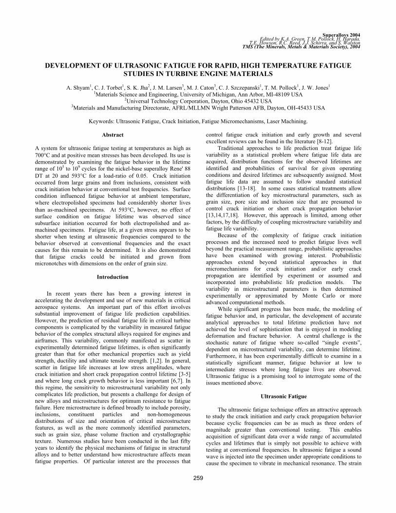
with a high resolution, non contacting fiber optic displacement
gage, also shown in Figure 2. In this figure, this probe is
measuring in a lateral mode although longitudinal mode
measurements are also possible. This optical probe system
provides a means to continuously measure displacement at anti-
nodal points in the specimen without disrupting the mechanical
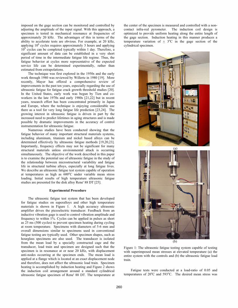
conditions required for resonance. An example of the linear
relationship between the displacement at the specimen end and
gage section strain, as measured by strain gages, is shown in
Figure 3. Importantly, the optical gage can be used without
interruption at all displacement amplitudes, and is not affected by
electrical noise resulting from induction heating.
Figure 2: A Rene' 88 DT specimen with the induction heating
setup. Also shown here is the non contacting fiber optic
displacement gage.
Figure 3: An experimentally generated linear calibration of
average strain at the center of the gage section with the
displacement amplitude at the end surfaces of the ultrasonic
fatigue specimen. represents microstrains.
Specimen dimensions were fixed using an analytical solution
for resonance, as described in the next section. The gage section
of the fatigue specimen was 16 mm long and had a diameter of 5
mm and overall dimensions are shown in Figure 4(a). The
material for this investigation came from the circumferential
orientation of a pancake shape forging. The forging had received
a supersolvus heat treatment prior to aging. In order to conserve
material for the fatigue tests, the ends of the specimen were made
of Inconel 718 and were inertia welded to the Rene' 88 DT gage
section. Electropolishing was used to remove approximately 0.1
mm from the diameter of the gage section. This was done to
eliminate surface compressive residual stresses arising from the
low stress grinding process [26]. Electropolishing was conducted
using an electrolyte of 55% ethanol with 35% butyl cellusolve and
10% perchloric acid at 40 V and -30oC.
The microstructure of Rene' 88 DT was examined by optical
microscopy and the grain-size distribution was determined using
standard linear intercept methods. The fatigue fracture surfaces
were studied using scanning electron microscopy (SEM). The
distance of the crack initiation site from the surface was measured
in all cases where a sub-surface crack initiation event occurred.
Micronotches were machined on some fatigue specimens
with the use of femtosecond pulsed lasers. The specimens were
mounted on a stage on an optics worktable. A Ti:sapphire
femtosecond laser system was used to produce 1000 laser pulses
per second at a wavelength of 780 nm, with each pulse 120 fs in
duration. The laser pulses were directed through a shutter which
opened for 100 ms (100 pulses) on to a 50 mm focal length plano-
convex lens and focused onto the specimen surface. The shutter
opening time was used to control the depth of the notch. Notches
of depth < 30 m and width 10 m could be made using this
procedure. Details of the laser notching procedure and its effects
in aluminum alloys and nickel-base superalloys could be found
elsewhere [27,28]. An important feature of the femtosecond laser
micromachining approach is the elimination of any melting or
261
heat affected zones typically encountered with conventional laser
drilling techniques [28].
Modeling of Ultrasonic Fatigue
A simple model for a fatigue specimen vibrating at a
resonant frequency of fres consists of two blocks of mass ‘m’
joined by a spring with a spring constant ‘k’. In a dumbbell
shaped specimen, the grip section approximates the mass and the
weightless gage section represents the ‘spring’. The resonant
frequency is then
(1)2
1
m
kfres
which gives the expected result of low mass objects having a
higher resonant frequency. The angular frequency is given by the
relationship = 2 fres. Equation (1), although approximate can
give useful insights to specimen design.
A much better representation of the displacement and strain
distribution of the fatigue specimen vibrating in resonance can be
achieved by solving the displacement equation for the propagation
of planar tension-compression waves in a resonant part [20]. A
dynamic force balance (neglecting damping effects) in the
longitudinal direction which allows for changing cross-sectional
area yields the following equation
(2)0)( 2 uEuAAu
where, u = u (x,t) is the displacement in the longitudinal (x)
direction, A is the cross-sectional area and A' is its gradient, is
the density and E is the elastic modulus in the longitudinal
direction. It is to be noted that time has been factored out in this
equation and the partial derivative of the displacement would give
the instantaneous strain in the x-direction. In the absence of area
gradients, the analytical solution of equation (2) would indicate a
sinusoidal variation [20]. If elastic modulus gradients exist in the
specimen (for example, as a result of heating the specimen) a
general force balance yields the following displacement equation
(3)0)]()[( 2 uEuEEAAu
where E' represents a modulus gradient. The strain and
displacement distributions in fatigue specimens were obtained by
solving Equation (2) for the room temperature case and by solving
Equation (3) for elevated temperatures. The solutions were
obtained numerically by executing a fourth order Runge Kutta
Nystrom (RKN) method within a JavaTM computer program. The
boundary conditions were implemented in the following fashion:
starting at the center of the gage section which is a displacement
node (with maximum known strain); the appropriate displacement
equation was iteratively evaluated until the specimen ends which
are displacement anti-nodes (with zero strain) are reached. The
known temperature variation of the modulus of the superalloy and
an experimentally measured temperature profile across the
specimen was embedded within the code. Since the strain
solutions are symmetric (and the displacement solutions are anti-
symmetric), only one half of the displacement/strain distribution
in the specimen was determined in the above manner.
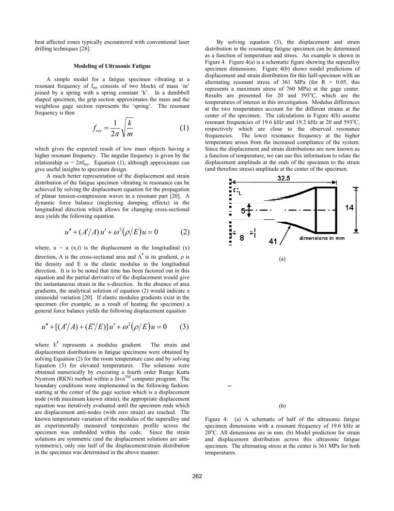
By solving equation (3), the displacement and strain
distribution in the resonating fatigue specimen can be determined
as a function of temperature and stress. An example is shown in
Figure 4. Figure 4(a) is a schematic figure showing the superalloy
specimen dimensions. Figure 4(b) shows model predictions of
displacement and strain distribution for this half-specimen with an
alternating resonant stress of 361 MPa (for R = 0.05, this
represents a maximum stress of 760 MPa) at the gage center.
Results are presented for 20 and 593oC, which are the
temperatures of interest in this investigation. Modulus differences
at the two temperatures account for the different strains at the
center of the specimen. The calculations in Figure 4(b) assume
resonant frequencies of 19.6 kHz and 19.2 kHz at 20 and 593oC,
respectively which are close to the observed resonance
frequencies. The lower resonance frequency at the higher
temperature arises from the increased compliance of the system.
Since the displacement and strain distributions are now known as
a function of temperature, we can use this information to relate the
displacement amplitude at the ends of the specimen to the strain
(and therefore stress) amplitude at the center of the specimen.
(a)
(b)
Figure 4: (a) A schematic of half of the ultrasonic fatigue
specimen dimensions with a resonant frequency of 19.6 kHz at
20oC. All dimensions are in mm. (b) Model prediction for strain
and displacement distribution across this ultrasonic fatigue
specimen. The alternating stress at the center is 361 MPa for both
temperatures.
262
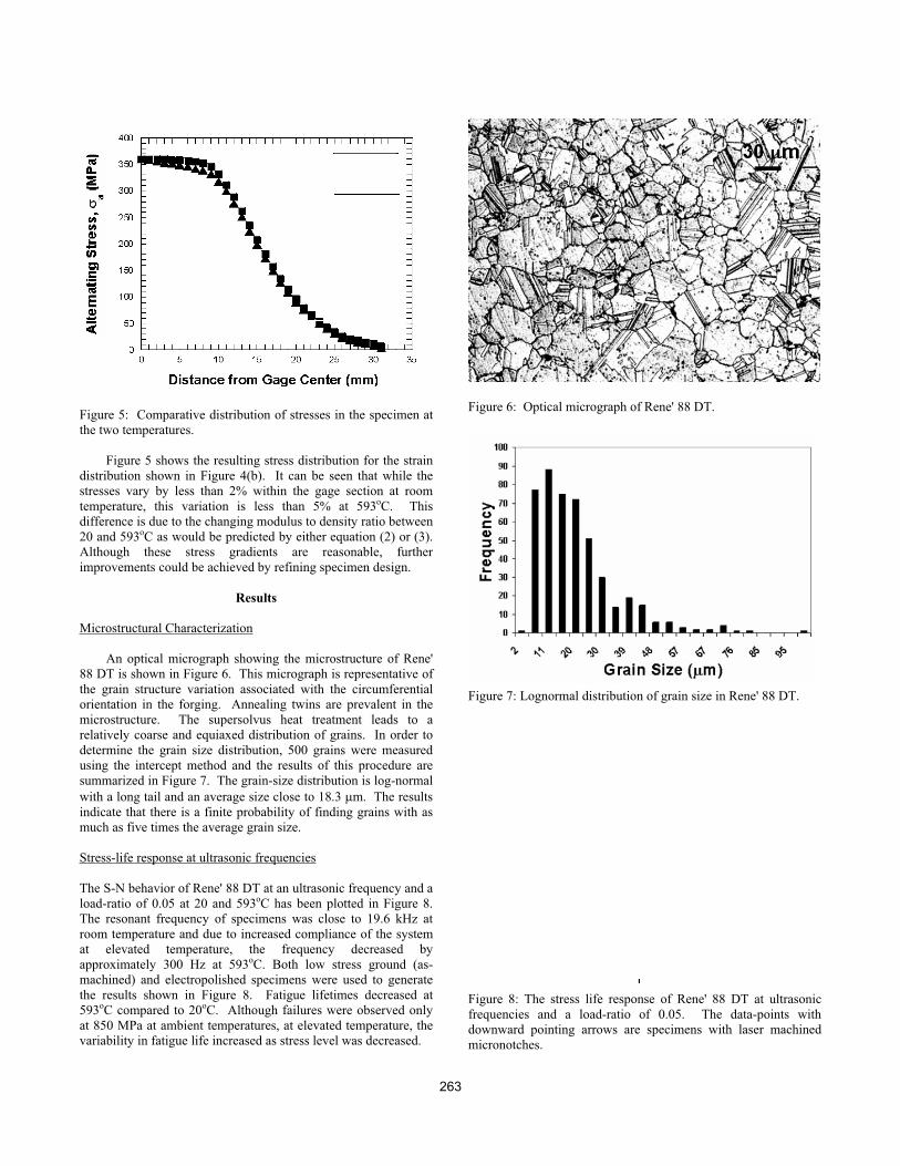
Figure 5: Comparative distribution of stresses in the specimen at
the two temperatures.
Figure 5 shows the resulting stress distribution for the strain
distribution shown in Figure 4(b). It can be seen that while the
stresses vary by less than 2% within the gage section at room
temperature, this variation is less than 5% at 593oC. This
difference is due to the changing modulus to density ratio between
20 and 593oC as would be predicted by either equation (2) or (3).
Although these stress gradients are reasonable, further
improvements could be achieved by refining specimen design.
Results
Microstructural Characterization
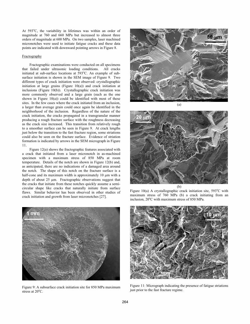
An optical micrograph showing the microstructure of Rene'
88 DT is shown in Figure 6. This micrograph is representative of
the grain structure variation associated with the circumferential
orientation in the forging. Annealing twins are prevalent in the
microstructure. The supersolvus heat treatment leads to a
relatively coarse and equiaxed distribution of grains. In order to
determine the grain size distribution, 500 grains were measured
using the intercept method and the results of this procedure are
summarized in Figure 7. The grain-size distribution is log-normal
with a long tail and an average size close to 18.3 m. The results
indicate that there is a finite probability of finding grains with as
much as five times the average grain size.
Stress-life response at ultrasonic frequencies
The S-N behavior of Rene' 88 DT at an ultrasonic frequency and a
load-ratio of 0.05 at 20 and 593oC has been plotted in Figure 8.
The resonant frequency of specimens was close to 19.6 kHz at
room temperature and due to increased compliance of the system
at elevated temperature, the frequency decreased by
approximately 300 Hz at 593oC. Both low stress ground (as-
machined) and electropolished specimens were used to generate
the results shown in Figure 8. Fatigue lifetimes decreased at
593oC compared to 20oC. Although failures were observed only
at 850 MPa at ambient temperatures, at elevated temperature, the
variability in fatigue life increased as stress level was decreased.
Figure 6: Optical micrograph of Rene' 88 DT.
Figure 7: Lognormal distribution of grain size in Rene' 88 DT.
Figure 8: The stress life response of Rene' 88 DT at ultrasonic
frequencies and a load-ratio of 0.05. The data-points with
downward pointing arrows are specimens with laser machined
micronotches.
263
At 593oC, the variability in lifetimes was within an order of
magnitude at 760 and 660 MPa but increased to almost three
orders of magnitude at 600 MPa. On two samples, laser machined
micronotches were used to initiate fatigue cracks and these data
points are indicated with downward pointing arrows in Figure 8.
Fractography
Fractographic examinations were conducted on all specimens
that failed under ultrasonic loading conditions. All cracks
initiated at sub-surface locations at 593oC. An example of sub-
surface initiation is shown in the SEM image of Figure 9. Two
different types of crack initiation were observed: crystallographic
initiation at large grains (Figure 10(a)) and crack initiation at
inclusions (Figure 10(b)). Crystallographic crack initiation was
more commonly observed and a large grain (such as the one
shown in Figure 10(a)) could be identified with most of these
sites. In the few cases where the crack initiated from an inclusion,
a larger than average grain could once again be identified in the
neighborhood of the inclusion. Regardless of the nature of the
crack initiation, the cracks propagated in a transgranular manner
producing a rough fracture surface with the roughness decreasing
as the crack size increased. This transition from relatively rough
to a smoother surface can be seen in Figure 9. At crack lengths
just below the transition to the fast fracture region, some striations
could also be seen on the fracture surface. Evidence of striation
formation is indicated by arrows in the SEM micrograph in Figure
11.
Figure 12(a) shows the fractographic features associated with
a crack that initiated from a laser micronotch in as-machined
specimen with a maximum stress of 850 MPa at room
temperature. Details of the notch are shown in Figure 12(b) and,
as anticipated, there are no indications of a damaged area around
the notch. The shape of this notch on the fracture surface is a
half-cone and its maximum width is approximately 10 m with a
depth of about 25 m. Fractographic observations suggest that
the cracks that initiate from these notches quickly assume a semi-
circular shape like cracks that naturally initiate from surface
flaws. Similar behavior has been observed in other studies of
crack initiation and growth from laser micronotches [27].
Figure 9: A subsurface crack initiation site for 850 MPa maximum
stress at 20oC.
(a)
(b)
Figure 10(a) A crystallographic crack initiation site, 593oC with
maximum stress of 760 MPa (b) a crack initiating from an
inclusion, 20oC with maximum stress of 850 MPa.
Figure 11: Micrograph indicating the presence of fatigue striations
just prior to the fast fracture regime.
264
(a)
(b)
Figure 12(a) Features of crack initiated from a laser micronotch
and (b) higher magnification image of the notch.
Figure 13: Effect of electropolishing on sub-surface crack
initiation. The horizontal line at an initiation distance of 50 m
indicates the boundary of the zone containing compressive
residual stresses from machining.
Discussion
We have demonstrated the applicability of ultrasonic fatigue
to test turbine disk superalloys at positive mean-stresses and
elevated temperatures (<600oC). With adjustments in the load
train and specimen design, we can test at temperatures higher than
600oC. Fatigue is a property of concern for many turbine engine
components [29]. Of particular relevance for disk materials is
quantification of any possible reduction in fatigue life due to small
processing defects or particular features of the microstructure
[30]. Ultrasonic testing provides opportunities for probing
failures from such small defects that may be activated at very long
lifetimes under nominally elastic fatigue conditions. In this
section, we examine these opportunities in light of our preliminary
results.
Sample Surface Conditions
As shown in Figure 8, surface condition influences the fatigue life
at room temperature but not at elevated temperature. This is
further illustrated in Figure 13, where the fatigue crack initiation
locations are plotted against fatigue life. At room temperature,
electropolished samples have a lifetime two orders of magnitude
less than as-machined specimens. This behavior is consistent with
the existence of surface residual compressive stresses from
machining. Recent work [26] has determined that compressive
residual stresses as high as 450 MPa can exist within the as-
machined layer of this superalloy. The inhibition of crack
initiation by residual stress is consistent with surface crack
initiation in electropolished specimens and only subsurface
initiation for as-machined specimens. On the other hand, as
shown in Figure 13, only sub-surface initiation occurs at elevated
temperature and there is no discernible effect of surface condition
on lifetime. It is possible that surface oxide formation may play a
role in retarding crack initiation by limiting surface slip [31]. It is
more likely that at elevated temperature, greater homogenization
of deformation [32] throughout the gage volume results in smaller
surface slip offset and therefore favors an interior crack initiation-
site with a large grain and/or inclusion while surface/near-surface
modes remain dormant. Clearly, the role of surface condition is
important and more work is required for a definitive explanation
of these results.
Micromechanisms of Crack Initiation and Growth
The results indicate that large grains in the size-range defined
by the far right tail of the grain-size distribution shown in Figure 7
play a dominant role in crack initiation. This indicates that fatigue
damage accumulation occurs more readily in the weaker regions
of the microstructure, in this case large favorably oriented grains.
In some cases inclusions in the neighborhood of large grains are
crack initiation sites.
Crack propagation is initially crystallographic along with
attendant rougher fracture surfaces but when the plastic zone size
becomes larger than the average grain size and multiple slip
systems can be activated, this leads to a smoother fracture surface
[33]. Transitions in crack growth mechanisms have been related
to both the monotonic [34] and reversed [34-36] plastic zone sizes
for several disk superalloys. The monotonic plastic zone (rpzs)
size is given by [37]
265
(4)6
1r
2
maxpzs
ys
K
where, Kmax represents the maximum stress intensity in the fatigue
cycle and ys is the monotonic yield stress. Assuming an
approximate stress intensity solution for an embedded elliptical
crack in a flat plate [38], and using yield stress values from Huron
[39] equation (4) can be used to predict the boundary for the
transition from a crystallographic growth mode to a nominally
mode I growth mode. In Figure 9, the crack size at which the
calculated maximum plastic zone size is equivalent to the average
grain-size is shown. As can be seen, this correlates well with the
observed transition in crack growth mode.
The total life of any component consists of the crack
initiation life, the small crack propagation life and the long crack
propagation life. Taylor and Knott [40] among others have
argued that a transition from small to long crack growth
mechanisms occurs when the size of the crack is approximately 10
times the size of the characteristic microstructural dimension such
as the grain size. If this is true, microstructural fracture
mechanics operates when the crack is less than 200 m in length
in this superalloy. The laser micronotching studies, in this
context, provide a unique opportunity for studying the interaction
of small cracks with the underlying microstructure. The notches
are loaded at an ultrasonic frequency and therefore growth rates
smaller than at the conventionally defined fatigue threshold (10-10
m/cycle) can also be recorded using this technique. Extension of
our current experimental capabilities to probe cracks at small
length scales comparable to microstructural dimensions and
growing at average rates smaller than one lattice spacing per cycle
is currently in progress.
Comparison with stress-life data at conventional frequency
A key issue in ultrasonic fatigue is whether fatigue behavior is
dependent on frequency, especially when elevated temperature
fatigue is studied. In Figure 14, we compare fatigue lifetime
derived from ultrasonic fatigue tests with lifetimes resulting from
a frequency of 10 and 20 Hz for specimens machined from the
same forging [26]. All of the data generated at lower frequency
was on electropolished specimens in load-control using a standard
servohydraulic test system. For comparative purposes, we have
reproduced the ultrasonic frequency fatigue data from
electropolished specimens only at room temperature and all the
data at elevated temperature (since there is no effect of surface
finish condition at 593oC). It can be seen that the fatigue strength
at 593oC is significantly lower in the ultrasonic tests. The
elevated temperature S-N curve at ultrasonic frequency has shifted
down by 250-300 MPa when compared to the low frequency S-N
curve. It is important to note the differences in the two
techniques. The ultrasonic technique is nominally elastic, so
direct comparison to a stress-controlled test at low frequency
under conditions where there are significant cyclic plastic strains
is not straightforward [26]. Although limited amount of
comparable data was generated at room temperature, Figure 14
suggests that the fatigue lives are similar at an ultrasonic
frequency and 10 Hz under ambient conditions with a slight
increase in fatigue life at 19.6 kHz. A small increase in fatigue
life for the superalloy Inconel 718 at ultrasonic frequency under
ambient conditions has been reported earlier by Chen et al. [41].
The crack initiation sites, however, are the same at both the
frequencies. Ultrasonic fatigue techniques can therefore, be used
as a tool to quickly identify the weakest links in the
microstructure.
Beyond the likely differences in the overall plastic strain
distribution in these two types of specimens, some of the variation
in fatigue lives with temperature and frequency may be associated
with thermally activated deformation mechanisms. These
mechanisms could be different in the vicinity of the crack
initiation sites. At room temperature, deformation is strain-rate
insensitive and this manifests as little or no effect of loading
frequency on fatigue lives or crack growth rates. As temperature
is increased from 20 to 593oC (at 10 Hz) or when frequency is
decreased from 19.6 kHz to 10 Hz (at 593oC), the fatigue lives
increase. It is known that increasing temperature (at the same
strain rate) and strain rate (at the same temperature) have opposite
effects on thermally activated deformation [42]. It is also known
that for several superalloys, fatigue cracks grow at faster rates as
temperature is increased and/or frequency is decreased [32]. The
above discussion, therefore, indicates that any decrease in fatigue
lives at ultrasonic frequencies (at 593oC) may be due to favorable
crack initiation conditions resulting from high frequency
deformation. The favorable condition at high frequency could be
higher values of slip offset (or more heterogeneously distributed
slip) which makes it easier to initiate a fatigue crack [43]. Atomic
force microscopy studies of slip offsets to investigate this
hypothesis are currently in progress.
Figure 14: Comparison of the S-N response of Rene' 88 DT
between conventional (10 Hz) and ultrasonic (20 kHz)
frequencies.
Conclusions
An ultrasonic fatigue test system has been developed that is
capable of superposed mean stresses and elevated
temperatures up to 700oC.
The fatigue behavior of Rene' 88 DT has been examined at
ultrasonic frequencies in lifetimes ranging from 105 to 109
for a load-ratio of 0.05 at 20 and 593oC.
Fatigue lifetime is dependent on surface condition at ambient
temperature but not at elevated temperature, where all crack
initiation sites were sub-surface.
266
All the crack initiation sites were associated with larger
grains or at inclusions near large grains.
It was demonstrated that micronotches produced by
femtosecond pulsed laser machining could be used
effectively to study crack initiation and propagation from
defects whose sizes are comparable to characteristic
microstructural dimensions.
These results indicate the potential for using fatigue as a tool
for examining the role microstructural variability on fatigue
life.
Acknowledgements
This work was supported by AFOSR under Grant F4620-03-1-
0069, Dr. Craig Hartley, Program Manager. The authors
acknowledge the support of Mr. David Maxwell in coordinating
the production of fatigue specimens.
References
1. J. Schijve, “Fatigue predictions and scatter”, Fatigue Fract.
Engng. Mater. Struct., 17 (1994) 381-396.
2. R.E. Little, E.H. Jebe, Statistical Design of Fatigue
Experiments, Wiley, 1975.
3. S. Suresh, Fatigue of Materials, 2nd Ed., Cambridge University
Press, 1998.
4. K.S. Ravichandran, R.O. Ritchie, Y. Murakami, Eds., Small
Fatigue Cracks: Mechanics, Mechanisms and Applications,
Elsevier, 1999.
5. K. J. Miller, E.R. de los Rios, eds, The Behavior of Short
Fatigue Cracks, EGF Pub, 1987, 461-478.
6. J. Schijve, P. De Rijk, “The fatigue crack propagation in 2024-
T3 alclad sheet materials from seven different manufacturers”,
Nat. Aerospace Lab., NRL, Amsterdam, TR M.2162, 1966.
7. D.A. Virlker, B. M. Hillberry, P.K. Goel, “The statistical nature
of fatigue crack propagation”, J. Engng Mat. Tech., 1011 (1979)
148-153.
8. C. Laird, “Fatigue”, in Physical Metallurgy, R.W. Cahn and P.
Haasen, Eds, Elsevier, 1986, 2294-2397.
9. D.L. Davidson, J. Lankford, “Fatigue crack growth in metals
and alloys: mechanisms and micromechanics”, Int. Mater. Rev.,
37 (1992) 45-76.
10. W Schutz, P. Heuler, “A review of fatigue life prediction
models for the crack initiation and propagation phases”, in
Advances in Fatigue Science and Technology, Kluwer Academic
Publishers, 1989, 177-219.
11. L. Lawson, E.Y. Chen, M. Meshii,, “Near threshold fatigue: a
review”, Int. J. Fatigue, 21 (1999) S15-S34.
12. J.W. Porvan, Z. H. Zhai, “A review of fatigue crack
initiation”, in Time-Dependent Fracture: Proceedings of the 11th
Canadian Fracture Conference, Martinus Nijhoff Publishers,
1985.
13. M. Goto, Statistical investigations of the behaviour of
microcracks in carbon steels”, Fatigue Fract. Engng Mater.
Struct., 14 (1991) 833-845.
14. M. Goto, Y. Yanagawa, H. Nisitani, “Statistical property in
the initiation and propagation of microcracks of a heat-treated
0.45% steel”, JSME Int. 22 (1990) 235-242.
15. H. Nisitani, M. Goto, “A small crack growth law and its
application to the evaluation of fatigue life”, in The Behavior of
Short Fatigue Cracks, K. J. Miller and E.R. de los Rios, eds, EGF
Pub, 1987, 461-478.
16. M. Goto, “Statistical investigation of the behavior of small
cracks and fatigue life in carbon steels with different ferrite grain
sizes”, Fatigue Fract. Engng Mater. Struct. 17 (1994) 635-649.
17. Q.C. Wang, D. Apelian, D.A. Lados, “Fatigue behavior of
A356-T6 aluminum cast alloys. Part I: Effect of casting defects”,
J. Light Metals, 1 (2001) 73-84.
18. Q.C. Wang, D. Apelian, D.A. Lados, “Fatigue behavior of
A356-T6 aluminum cast alloys. Part II: Effect of microstructural
constituents, J. Light Metals, 1 (2001) 85-97.
19. L.E. Willertz, “Ultrasonic fatigue”, Int. Met. Rev., 25 (1980)
65-78.
20. H. Mayer, “Fatigue crack growth and threshold measurements
at very high frequencies”, Int. Mat. Rev., 44 (1999) 1-36.
21. J.K. Tien, “High-Power, Ultrasonic Fatigue Testing Machine”,
Rev. Sci. Instrum., 46 (1975) 840-846.
22. J.M. Wells, O. Buck, L.D. Roth and J.K. Tien, eds.,
Ultrasonic Fatigue, Proceedings, TMS/AIME, 1982.
23. S. Stanzl-Tschegg, H. Mayer, Eds., Proceedings of the
International Conference on Fatigue in the Very High Cycle
Regime, Institute of Meteorology and Physics, Vienna, 2001.
24. S. Stanzl-Tschegg, “Ultrasonic Fatigue”, in Fatigue ’96: Sixth
International Fatigue Congress, Elsevier Science Inc., 1996,
1887-1898.
25. D.D. Krueger, R.D. Kissinger, R.G. Menzies, “Development
and introduction of a damage tolerant high temperature nickel-
base disk alloy, Rene' 88 DT”, in Superalloys 1992, S.D.
Antolovich et al., eds., TMS-AIME, 1992, 277-286.
26. M.J. Caton, S.K. Jha, A.H. Rosenberger, J.M. Larsen,
“Divergence of Mechanisms and its effect on variability in
Fatigue life of Rene' 88 DT”, Superalloys 2004.
27. A. Shyam, Y.N. Picard, J.W. Jones, J.E. Allison, S.M.
Yalisove, “Small fatigue crack propagation from micronotches in
the cast aluminum alloy W319”, Scripta Mater., 50 (2004) 1109-
1114.
267
28. Q. Feng, Y.N. Picard, H. Liu, S.M. Yalisove, G. Mourou,
T.M. Pollock, “Femtosecond laser micromachining of single-
crystal superalloys”, Superalloys 2004.
29. B.A. Cowles, “High cycle fatigue in aircraft gas turbines - an
industry perspective”, Int. J. Fract., 80 (1996) 147-163.
30. E.S. Huron, P.G. Roth, “The influence of inclusions on low
cycle fatigue life in a P/M nickel-base disk superalloy”, in
Superalloys 1996, R.D. Kissinger et al., eds., TMS-AIME, 1996,
359-367.
31. J. E. King, “Role of oxides in fatigue crack propagation”,
Mater. Sci. Technol., 6 (1990) 19-31.
32. J. E. King, “Fatigue crack propagation in nickel-base
superalloys - effects of microstructure, load ratio, and
temperature”, Mater. Sci. Technol., 3 (1987) 750-764.
33. A. Shyam, W.W. Milligan, “Effects of deformation behavior
on fatigue fracture surface morphology in a nickel-base
superalloy”, Acta Mater., 52 (2004) 1503-1513.
34. P.A.S. Reed, W.F. Gale, J.E. King, “Intrinsic threshold in
polycrystalline Udimet 720”, Mater. Sci. Technol., 9 (1993) 281–
287.
35. J.E. King, “Effects of grain size and microstructure on
threshold value and near-threshold crack growth in powder-
formed Ni-base superalloy” Met. Sci. 16 (1982) 345–355.
36. J. Luo, P. Bowen, “Small and long fatigue crack growth
behaviour of a PM Ni-based superalloy, Udimet 720”, Int. J.
Fatigue, 26 (2004) 113-124.
37. T.L. Anderson, Fracture Mechanics – Fundamentals and
Applications, 2nd Edition, CRC Press, 1994, 72-75.
38. Y. Murakami, Ed. in chief, Stress Intensity Factors Handbook,
Vol. 2, Pergamon, 1987, 712-713.
39. E.S. Huron, “Serrated yielding in a nickel-base superalloy”, in
Superalloys 1992, S.D. Antolovich et al., eds., TMS-AIME, 1992,
675-684.
40. D. Taylor, J.F. Knott, “Fatigue crack propagation behaviour of
small cracks; the effect of microstructure”, Fatigue Fract. Eng.
Mater. Struct., 4 (1981) 147–155.
41. Q. Chen, N. Kawagoishi, K. Othubo, E. Kondo, M. Sakai, T.
Kizaki “Ultrasonic fatigue strength in Inconel 718”, in Fifth
International Symposium on Superalloys 718, 625, 706 and
Various Derivatives, E.A. Loria, ed., TMS-AIME, 2001, 573-582.
42. G. E. Dieter, Mechanical Metallurgy, SI Metric Edition,
McGraw-Hill, 1988, 275-324.
43. J.C. Williams, E.A. Starke Jr., “Progress in structural
materials for aerospace systems”, Acta Mater., 51 (2003) 5775-
5799.
268


![Fatigue Flaw NDE Reference Standard Development - Phase … · ultrasonic testing (UT), ... (EMAT), phased array ultrasound, and long-range guided wave (LRGW)]; electromagnetic methods](https://static.fdocuments.in/doc/165x107/5ac244ba7f8b9ae45b8e57f7/fatigue-flaw-nde-reference-standard-development-phase-testing-ut-emat.jpg)