
High Performance Handheld Base Station Analyzer Specifications 4 of 36 PN: 11410-00698 Rev. W...
36
Technical Data Sheet BTS Master™ High Performance Handheld Base Station Analyzer MT8220T 400 MHz to 6.0 GHz Cable and Antenna Analyzer 150 kHz to 7.1 GHz Spectrum Analyzer 10 MHz to 7.1 GHz Power Meter
Transcript of High Performance Handheld Base Station Analyzer Specifications 4 of 36 PN: 11410-00698 Rev. W...

Technical Data Sheet
BTS Master™High Performance Handheld Base Station Analyzer
MT8220T400 MHz to 6.0 GHz Cable and Antenna Analyzer150 kHz to 7.1 GHz Spectrum Analyzer10 MHz to 7.1 GHz Power Meter

MT8220T Specifications
2 of 36 PN: 11410-00698 Rev. W MT8220T TDS
Introduction Anritsu introduces the next generation high performance handheld Base Station Analyzer for installation and maintenance of wireless networks. Delivered with a standard three-year warranty, the MT8220T BTS Master is the only all-in-one, touchscreen handheld tool that combines cable and antenna testing, signal analysis for all cellular standards, ultra-sensitive spectrum analysis, sophisticated interference tracking, and a vector signal generator for receiver testing in a compact, easy-to-use instrument.
Cable and Antenna Analyzer Highlights
Spectrum and Interference Analyzer Highlights
Capabilities and Functional Highlights
• Measurements: RL, VSWR, Cable Loss, DTF, Phase, Gain• 2-port Gain Measurement Uncertainty: < 0.45 dB• 2-port Dynamic Range: > 100 dB
• RF Immunity: +17 dBm on-channel, +10 dBm on-frequency• Calibration: OSL and FlexCal™• Bias Tee: 32 V internal
• Measurements: Occupied Bandwidth, Channel Power, ACPR, C/I, Field Strength, Spectral Emissions
• Interference Analyzer: Spectrogram, Signal Strength, RSSI, Signal ID
• Dynamic Range: > 95 dB in 1 Hz RBW• DANL: –163 dBm in 1 Hz RBW
• Phase Noise: –100 dBc/Hz @ 10 kHz offset• Frequency Accuracy: ± 2.5 × 10⁻⁸ with GPS On• Burst Detect™ Sweep Mode: sweep 1000x in 15 MHz span• Coverage Mapping: plot RSSI to on-screen map• Interference Mapping: on-screen mapping with
triangulation
• CPRI LTE RF Measurements• BBU Emulation ALu-Nokia LTE• Remote Electrical Tilt (RET) antenna monitoring and control• OBSAI LTE RF Measurements• LTE/LTE-A FDD/TDD; MIMO (2x2, 4x4)• GSM/GPRS/EDGE• W-CDMA/HSPA+• TD-SCDMA/HSPA+• CDMA/EV-DO • WiMAX Fixed/Mobile• Vector Signal Generator• Zero-span IF Output• Gated Sweep
• Standard GPS receiver, GPS information on stored traces• PIM Alert Application• Standard Internal Preamp• Internal Power Meter• High Accuracy Power Meter• USB Power Sensors up to 26 GHz• Channel Scanner• 2.5 hour battery operation time• < 5 minute warm-up time• Ethernet/USB data transfer• Remote Access Tool• Line Sweep Tools• Standard 3-year warranty
BTS Master™ MT8220T Base Station Analyzer featuring Vector Signal GeneratorHandheld Size: 315 mm x 211 mm x 102 mm (12.4 in x 8.3 in x 4.0 in), Lightweight: 4.7 kg (10.3 lb)

Specifications MT8220T
MT8220T TDS PN: 11410-00698 Rev. W 3 of 36
Table of Contents
Definitions. . . . . . . . . . . . . . . . . . . . . . . . . . . . . . . . . . . . . . . . . . . . . . . . . . . . . . . . . . . . . . . . . . . . . . . . . . . . . . . . . . . . . 3Cable and Antenna Analyzer . . . . . . . . . . . . . . . . . . . . . . . . . . . . . . . . . . . . . . . . . . . . . . . . . . . . . . . . . . . . . . . . . . . . . 4Spectrum Analyzer . . . . . . . . . . . . . . . . . . . . . . . . . . . . . . . . . . . . . . . . . . . . . . . . . . . . . . . . . . . . . . . . . . . . . . . . . . . . . 6GPS Receiver. . . . . . . . . . . . . . . . . . . . . . . . . . . . . . . . . . . . . . . . . . . . . . . . . . . . . . . . . . . . . . . . . . . . . . . . . . . . . . . . . . . 8Power Meter . . . . . . . . . . . . . . . . . . . . . . . . . . . . . . . . . . . . . . . . . . . . . . . . . . . . . . . . . . . . . . . . . . . . . . . . . . . . . . . . . . . 8High Accuracy Power Meter (Option 19) . . . . . . . . . . . . . . . . . . . . . . . . . . . . . . . . . . . . . . . . . . . . . . . . . . . . . . . . . . . 8Bias-Tee (Option 10) . . . . . . . . . . . . . . . . . . . . . . . . . . . . . . . . . . . . . . . . . . . . . . . . . . . . . . . . . . . . . . . . . . . . . . . . . . . . 9Vector Signal Generator (Option 23) . . . . . . . . . . . . . . . . . . . . . . . . . . . . . . . . . . . . . . . . . . . . . . . . . . . . . . . . . . . . . . 9I/Q Waveform Capture (Option 24). . . . . . . . . . . . . . . . . . . . . . . . . . . . . . . . . . . . . . . . . . . . . . . . . . . . . . . . . . . . . . .10Interference Analyzer (Option 25). . . . . . . . . . . . . . . . . . . . . . . . . . . . . . . . . . . . . . . . . . . . . . . . . . . . . . . . . . . . . . . .10Channel Scanner (Option 27) . . . . . . . . . . . . . . . . . . . . . . . . . . . . . . . . . . . . . . . . . . . . . . . . . . . . . . . . . . . . . . . . . . . .10Zero Span IF Output (Option 89) . . . . . . . . . . . . . . . . . . . . . . . . . . . . . . . . . . . . . . . . . . . . . . . . . . . . . . . . . . . . . . . . .11Gated Sweep (Option 90) . . . . . . . . . . . . . . . . . . . . . . . . . . . . . . . . . . . . . . . . . . . . . . . . . . . . . . . . . . . . . . . . . . . . . . .11Coverage Mapping (Option 431) . . . . . . . . . . . . . . . . . . . . . . . . . . . . . . . . . . . . . . . . . . . . . . . . . . . . . . . . . . . . . . . . .11RF over Fiber Hardware (Option 759) . . . . . . . . . . . . . . . . . . . . . . . . . . . . . . . . . . . . . . . . . . . . . . . . . . . . . . . . . . . . .11CPRI LTE RF Measurements (Option 752) . . . . . . . . . . . . . . . . . . . . . . . . . . . . . . . . . . . . . . . . . . . . . . . . . . . . . . . . .12CPRI Base Band Unit Emulation ALu-Nokia LTE (Option 760). . . . . . . . . . . . . . . . . . . . . . . . . . . . . . . . . . . . . . . . .14Remote Electrical Tilt (RET) Device Test (Option 761). . . . . . . . . . . . . . . . . . . . . . . . . . . . . . . . . . . . . . . . . . . . . . . .15OBSAI LTE RF Measurements (Option 753) . . . . . . . . . . . . . . . . . . . . . . . . . . . . . . . . . . . . . . . . . . . . . . . . . . . . . . . .16GSM/GPRS/EDGE Measurements (Option 880). . . . . . . . . . . . . . . . . . . . . . . . . . . . . . . . . . . . . . . . . . . . . . . . . . . . .17W-CDMA/HSPA+ Measurements (Option 881) . . . . . . . . . . . . . . . . . . . . . . . . . . . . . . . . . . . . . . . . . . . . . . . . . . . . .18TD-SCDMA/HSPA+ Measurements (Option 882). . . . . . . . . . . . . . . . . . . . . . . . . . . . . . . . . . . . . . . . . . . . . . . . . . . .19LTE/LTE-A FDD/TDD Measurements (Options 883 and 886) . . . . . . . . . . . . . . . . . . . . . . . . . . . . . . . . . . . . . . . . . .20CDMA/EV-DO Measurements (Option 884) . . . . . . . . . . . . . . . . . . . . . . . . . . . . . . . . . . . . . . . . . . . . . . . . . . . . . . . .22WiMAX Fixed/Mobile Measurements (Option 885). . . . . . . . . . . . . . . . . . . . . . . . . . . . . . . . . . . . . . . . . . . . . . . . . .24General Specifications . . . . . . . . . . . . . . . . . . . . . . . . . . . . . . . . . . . . . . . . . . . . . . . . . . . . . . . . . . . . . . . . . . . . . . . . .26Line Sweep Tools™ . . . . . . . . . . . . . . . . . . . . . . . . . . . . . . . . . . . . . . . . . . . . . . . . . . . . . . . . . . . . . . . . . . . . . . . . . . . .27Master Software Tools™ . . . . . . . . . . . . . . . . . . . . . . . . . . . . . . . . . . . . . . . . . . . . . . . . . . . . . . . . . . . . . . . . . . . . . . . .27easyMap Tools™. . . . . . . . . . . . . . . . . . . . . . . . . . . . . . . . . . . . . . . . . . . . . . . . . . . . . . . . . . . . . . . . . . . . . . . . . . . . . . .28Web Remote Control. . . . . . . . . . . . . . . . . . . . . . . . . . . . . . . . . . . . . . . . . . . . . . . . . . . . . . . . . . . . . . . . . . . . . . . . . . .28Programmable Remote Control . . . . . . . . . . . . . . . . . . . . . . . . . . . . . . . . . . . . . . . . . . . . . . . . . . . . . . . . . . . . . . . . .28Ordering Information – Instrument Options . . . . . . . . . . . . . . . . . . . . . . . . . . . . . . . . . . . . . . . . . . . . . . . . . . . . . .29Standard Accessories . . . . . . . . . . . . . . . . . . . . . . . . . . . . . . . . . . . . . . . . . . . . . . . . . . . . . . . . . . . . . . . . . . . . . . . . . .30Manuals. . . . . . . . . . . . . . . . . . . . . . . . . . . . . . . . . . . . . . . . . . . . . . . . . . . . . . . . . . . . . . . . . . . . . . . . . . . . . . . . . . . . . .30Troubleshooting Guides . . . . . . . . . . . . . . . . . . . . . . . . . . . . . . . . . . . . . . . . . . . . . . . . . . . . . . . . . . . . . . . . . . . . . . . .30Power Sensors . . . . . . . . . . . . . . . . . . . . . . . . . . . . . . . . . . . . . . . . . . . . . . . . . . . . . . . . . . . . . . . . . . . . . . . . . . . . . . . .30Optional Accessories. . . . . . . . . . . . . . . . . . . . . . . . . . . . . . . . . . . . . . . . . . . . . . . . . . . . . . . . . . . . . . . . . . . . . . . . . . .31
Definitions All specifications and characteristics apply to Revision 2 instruments under the following conditions, unless otherwise stated:
Warm-Up Time After 10 minutes of warm-up time, where the instrument is left in the ON state.Reference Signal When using internal reference signal.Time Base Error Time base error = frequency accuracy x measured frequency
Typical Performance Typical specifications in parenthesis () represent the mean value of measured units and do not include any guard-bands or uncertainties. They are not warranted.Typical specifications that are not in parenthesis are not tested and not warranted. They are generally representative of characteristic performance.
Uncertainty A coverage factor of x1 is applied to the measurement uncertainties to facilitate comparison with other industry handheld analyzers.
Calibration Cycle Calibration is within the recommended 12 month period (residual specifications also require calibration kit calibration cycle adherence.)

MT8220T Specifications
4 of 36 PN: 11410-00698 Rev. W MT8220T TDS
Cable and Antenna Analyzer
Measurements Measurements VSWR, Return Loss, Cable Loss, Distance-to-Fault (DTF) VSWR, Distance-to-Fault (DTF) Return Loss, 1-port
Phase, 2-port Phase , 2-port Gain, Smith Chart
Setup Parameters Frequency Start/Stop, Signal Standard, Start Cal
DTF Start/Stop, DTF Aid, Units (m/ft), Cable Loss, Propagation Velocity, Cable, WindowingWindowing Rectangular, Normal Side Lobe, Low Side Lobe, Minimum Side LobeAmplitude Top, Bottom, Auto Scale, Full Scale
Sweep Run/Hold, Single/Continuous, RF Immunity (High/Low), Data Points, Averaging/Smoothing, Output Power (High/Low)
Data Points 137, 275, 551Markers Markers 1 to 6 each with a Delta Marker, Marker to Peak/Valley, Time Marker (DTF), Marker Table (On/Off),
All Markers OffTraces Recall, Copy to Display Memory, No Trace Math, Trace ± Memory, Trace Overlay (On/Off)
Limit Line On/Off, Single Limit, Multi-segment Edit, Limit Alarm (On/Off), Pass Fail Message (On/Off), Warning Limit Offset, Clear Limit
Limit Line Edit Frequency, Amplitude, Add Point, Delete Point, Next Point Left, Next Point Right, Move LimitCalibration Start Cal, 1/2-port, Low/High Power, Standard/FlexCal™, DUT Connector, Configure DUTSave/Recall Setups, Measurements, Screen Shots (JPEG - save only)
Application Options Bias-Tee (On/Off)
Frequency Frequency Range 400 MHz to 6 GHz
Frequency Accuracy ± 3.0 × 10⁻⁶ Frequency Resolution 1 kHz (RF immunity low)
100 kHz (RF immunity high)
Output Power High –7 dBm, typical, 1 or 2-portLow –40 dBm, typical, 2-port
Dynamic Range (output power high, 25-trace average)400 MHz to 2800 MHz > 100 dB, 110 dB typical
> 2800 MHz to 4000 MHz > 90 dB> 4000 MHz to 6000 MHz > 85 dB
Interference Immunity On-Channel +17 dBm @ >1.0 MHz from carrier frequency
On-Frequency +10 dBm within ±10 kHz from the carrier frequency
Measurement Speed Return Loss ≤ 4.5 ms/data point, RF immunity low, typical
Distance-to-Fault ≤ 4.5 ms/data point, RF immunity low, typical
Return Loss Measurement Range 0 dB to 60 dB
Resolution 0.01 dB
VSWR Measurement Range 1:1 to 65:1
Resolution 0.01
Cable Loss Measurement Range 0 dB to 30 dB
Resolution 0.01 dB
2-Port Gain Measurement Range –120 dB to +100 dB
Resolution 0.01 dB
Specifications MT8220T
MT8220T TDS PN: 11410-00698 Rev. W 5 of 36
Cable and Antenna Analyzer (continued)
Distance-to-Fault Vertical Range Return Loss 0 dB to 60 dB
Vertical Range VSWR 1 to 65Fault Resolution (m) (1.5 × 10⁸ × Vp) / ∆F (Vp = velocity propagation constant, ∆F is F2 - F1 in Hz)
Horizontal Range (m) 0 to (Data Points-1) × Fault Resolution, to a maximum of 1500 m (4921 ft)
Phase (1- and 2-Port) Measurement Range –180° to +180°
Resolution 0.01°
Smith Chart Resolution 0.01
Measurement Accuracy Corrected Directivity > 42 dB
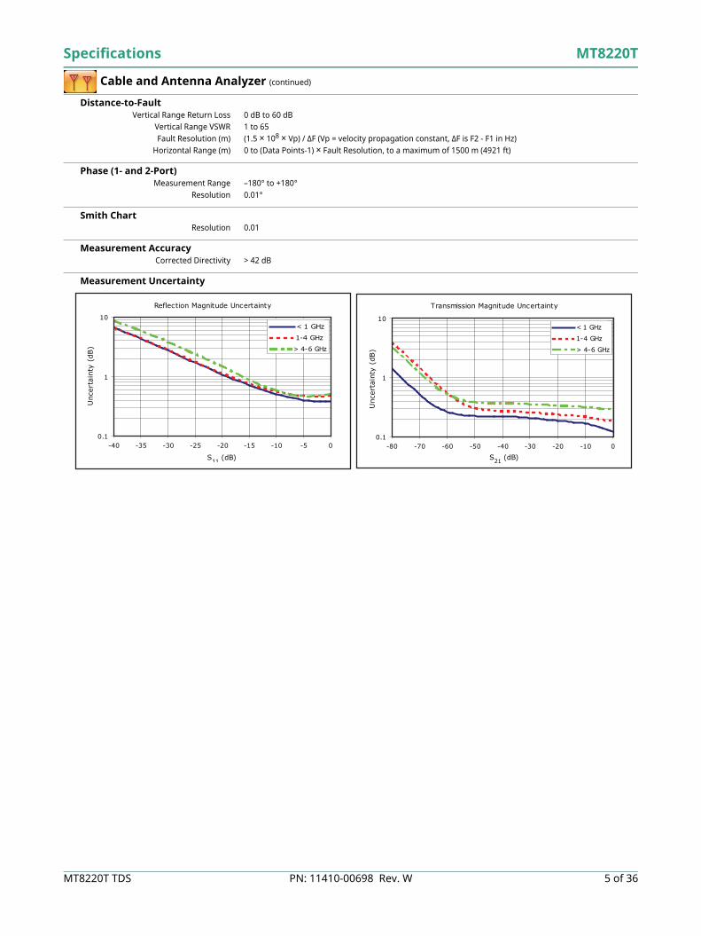
Measurement Uncertainty
Reflection Magnitude Uncertainty
0.1
1
10
-40 -35 -30 -25 -20 -15 -10 -5 0
S11 (dB)
Unc
erta
inty
(dB
)
< 1 GHz
1-4 GHz
> 4-6 GHz
Transmission Magnitude Uncertainty
0.1
1
10
-80 -70 -60 -50 -40 -30 -20 -10 0
S21 (dB)
Unc
erta
inty
(dB
)
< 1 GHz
1-4 GHz
> 4-6 GHz
MT8220T Specifications
6 of 36 PN: 11410-00698 Rev. W MT8220T TDS
Spectrum Analyzer
Measurements Smart Measurements Field Strength (uses antenna calibration tables to measure dBm/m2, dBµV/m, dBV/m, dBmV/m, V/m, W/m2,
dBW/m2, A/m, dBA/m and W/cm2)Occupied Bandwidth (measures 99 % to 1 % power channel of a signal)Channel Power (measures the total power in a specified bandwidth)ACPR (adjacent channel power ratio)AM/FM/SSB Demodulation (AM, wide/narrow FM, upper/lower SSB), (audio out only)C/I (carrier-to-interference ratio)Emission Mask (recall limit lines as emission mask)Coverage Mapping (requires Option 431)IQ Waveform Capture (requires Option 24)PIM Alert Application (available for download)
Setup Parameters Frequency Center/Start/Stop, Span, Frequency Step, Frequency Offset, Signal Standard, Channel #Amplitude Reference Level (RL), Scale, Attenuation Auto/Level, RL Offset, Pre-Amp On/Off, Detection
Span Span, Span Up/Down (1-2-5), Full Span, Zero Span, Last SpanBandwidth RBW, Auto RBW, VBW, Auto VBW, RBW/VBW Ratio, Span/RBW Ratio
Application Options Bias-Tee (On/Off), Impedance (50 , 75 , Other)
Sweep Functions Sweep Single/Continuous, Manual Trigger, Reset, Detection, Minimum Sweep Time, Trigger Type,
Gated Sweep (requires Option 90)Sweep Mode Fast (100x Performance), Performance, No FFT, Burst Detect (1000x Fast in 15 MHz span)
Detection Peak, RMS/Avg, Negative, Sample, Quasi-peakTriggers Free Run, External, Video, Change Position, Manual
Trace Functions Traces Up to three Traces (A, B, C), View/Blank, Write/Hold, Trace A/B/C Operations
Trace A Operations Normal, Max Hold, Min Hold, Average, # of Averages, (always the live trace)Trace B Operations A B, B C, Max Hold, Min HoldTrace C Operations A C, B C, Max Hold, Min Hold, A – B C, B – A C, Relative Reference (dB), Scale
Marker Functions Markers Markers 1-6 each with a Delta Marker, or Marker 1 Reference with Six Delta Markers,
Marker Table (On/Off/Large), All Markers OffMarker Types Style (Fixed/Tracking), Noise Marker, Frequency Counter Marker
Marker Auto-Position Peak Search, Next Peak (Right/Left), Peak Threshold %, Set Marker to Channel, Marker Frequency to Center, Delta Marker to Span, Marker to Reference Level
Marker Table 1-6 markers frequency and amplitude, plus delta markers frequency offset and amplitude
Limit Line Functions Limit Lines Upper/Lower, On/Off, Edit, Move, Envelope, Advanced, Limit Alarm, Default Limit
Limit Line Edit Frequency, Amplitude, Add Point, Add Vertical, Delete Point, Next Point Left/RightLimit Line Move To Current Center Frequency, By dB or Hz, To Marker 1, Offset from Marker 1
Limit Line Envelope Create Envelope, Update Amplitude, Number of Points (41), Offset, Shape Square/SlopeLimit Line Advanced Type (Absolute/Relative), Mirror, Save/Recall
Frequency Frequency Range 150 kHz to 7.1 GHz (usable to 0 Hz)
Maximum Continuous Input +30 dBmTuning Resolution 1 Hz
Frequency Reference Aging: ± 1.0 × 10⁻⁶/10 yearsFrequency Span Accuracy ± 3 × 10⁻⁷ (25 °C ± 25 °C) + aging, 10 Hz to 7.1 GHz including zero span
Sweep Time Minimum 100 ms, 10 s to 600 s in zero spanSweep Time Accuracy ± 2 % in zero span
Bandwidth Resolution Bandwidth (RBW) 1 Hz to 3 MHz in 1–3 sequence ± 10 % (–3 dB bandwidth)
Video Bandwidth (VBW) 1 Hz to 3 MHz in 1–3 sequence ± 10 % (–3 dB bandwidth)RBW with Quasi-Peak Detection 200 Hz, 9 kHz, 120 kHz (–6 dB bandwidth)VBW with Quasi-Peak Detection Auto VBW is On, RBW/VBW = 1
VBW/Average Type Linear/Log
Spectral Purity SSB Phase Noise –100 dBc/Hz @ 10 kHz, 20 kHz, and 30 kHz offset from carrier
–102 dBc/Hz @ 100 kHz offset from carrier

Specifications MT8220T
MT8220T TDS PN: 11410-00698 Rev. W 7 of 36
Spectrum Analyzer (continued)
Amplitude Ranges Dynamic Range > 95 dB (600 MHz, 3.5 GHz), 2/3 (TOI-DANL) in 1 Hz RBW
Measurement Range DANL to +30 dBmDisplay Range 1 to 15 dB/div in 1 dB steps, ten divisions displayed
Reference Level Range –120 dBm to +30 dBmAttenuator Resolution 0 dB to 65 dB, 5.0 dB steps
Amplitude Units Log Scale Modes: dBm, dBV, dBmV, dBμV, dBW, dBALinear Scale Modes: nV, μV, mV, V, kV, nW, μW, mW, W, kW, fA, pA, nA, μA, mA, A
Amplitude Accuracy (Power level > –50 dBm)
Displayed Average Noise Level (DANL)
Spurs Residual Spurs Preamp Off (RF input terminated, 0 dB input attenuation)
–90 dBm, 150 kHz to 3.2 GHz–84 dBm, > 3.2 GHz to 7.1 GHz
Exceptions –70 dBm @ 3200 MHzPreamp On (RF input terminated, 0 dB input attenuation)–100 dBm, 10 MHz to 7.1 GHz
Exceptions –95 dBm @ 50 MHz, 100 MHz, 150 MHzInput-Related Spurious (0 dB attenuation, –30 dBm input, span < 1.7 GHz, carrier offset > 4.5 MHz)
–60 dBc, –70 dBc typicalExceptions –40 dBc, –60 dBc typical @ 1672 MHz
Third-Order Intercept (TOI) Preamp Off
600 MHz +8 dBm typical3.5 GHz +9 dBm typical
Second Harmonic Distortion Preamp Off –50 dBc maximum
–70 dBc typical
VSWR < 4.0 GHz 1.5:1 typical
4.0 GHz to 7.1 GHz 1.8:1 typical
Input attenuationPreamp Off
(≤ 35 dB)Preamp Off(40 to 55 dB)
Preamp Off(60 to 65 dB)
Preamp On(0 or 10 dB)
150 kHz to ≤10 MHz ± 1.50 dB ± 1.50 dB ± 1.50 dB -150 kHz to 4.0 GHz - - - ± 1.50 dB
>10 MHz to 4.0 GHz ± 1.25 dB ± 1.75 dB ± 1.75 dB ->4.0 GHz to 6.5 GHz - ± 1.75 dB ± 1.75 dB ->4.0 GHz to 7.1 GHz ± 1.75 dB - - ± 1.75 dB>6.5 GHz to 7.1 GHz - ± 2.00 dB ± 3.00 dB -
Preamp Off(Reference level –20 dBm)
Preamp On(Reference level –50 dBm)
DANL in 1 Hz RBW, 0 dB attenuation Maximum Typical Maximum Typical3 MHz to 1.0 GHz –137 dBm –150 dBm –161 dBm –163 dBm
> 1.0 GHz to 2.2 GHz –133 dBm –147 dBm –159 dBm –160 dBm> 2.2 GHz to 4.0 GHz –133 dBm –143 dBm –156 dBm –159 dBm> 4.0 GHz to 7.1 GHz –130 dBm –138 dBm –154 dBm –156 dBm

MT8220T Specifications
8 of 36 PN: 11410-00698 Rev. W MT8220T TDS
GPS Receiver
General Setup On/Off, Antenna Voltage 3.3 V/5.0 V, GPS Info
GPS Time/Location Indicator Time, Latitude, Longitude and Altitude on displayTime, Latitude, Longitude and Altitude with trace storage
High Frequency Accuracy Spectrum Analyzer, Interference Analyzer, Wireless Measurementswhen GPS Antenna is connected:± 2.5 × 10⁻⁸ with GPS On, 3 minutes after satellite lock in selected mode
GPS Lock Accuracy after antenna is disconnected:± 5.0 × 10⁻⁸ for 3 days, 0 ºC to 50 ºC ambient temperature
Connector SMA, female Supplied Antenna 2000-1760-R GPS Antenna, SMA(m), 25 dB gain, 2.5 VDC to 3.7 VDC
Power Meter
General Frequency Center/Start/Stop, Span, Frequency Step, Signal Standard, Channel #, Full BandAmplitude Maximum, Minimum, Offset, Relative On/Off, Units, Auto Scale
Average Acquisition Fast/Med/Slow, # of Running AveragesLimits Limit On/Off, Limit Upper/Lower
Frequency Range 10 MHz to 7.1 GHzSpan 1 kHz to 100 MHz
Display Range –140 dBm to +30 dBm, ≤ 40 dB spanMeasurement Range –120 dBm to +30 dBm
Offset Range 0 dB to +100 dBVSWR 1.5:1 typical
Maximum Power +30 dBm without attenuatorAccuracy Same as Spectrum Analyzer
Application Options Impedance (50 Ω, 75 Ω, Other)
High Accuracy Power Meter (Option 19) (requires external USB power sensor, sold separately)
Amplitude Maximum, Minimum, Offset, Relative On/Off, Units, Auto ScaleAverage # of Running Averages, Max HoldZero/Cal Zero On/Off, Cal Factor (Center Frequency, Signal Standard)
Limits Limit On/Off, Limit Upper/Lower
Power Sensor Model MA24105A MA24106A MA24108A/18A/26A MA24208A/18A MA24330A/40A/50A
Description Inline High Power Sensor
High Accuracy RF Power Sensor
Microwave USB Power Sensor
Microwave Universal USB Power Sensor
Microwave CW USB Power Sensor
Frequency Range 350 MHz to 4 GHz 50 MHz to 6 GHz 10 MHz to 8/18/26 GHz
10 MHz to 8/18 GHz 10 MHz to 33/40/50 GHz
Connector Type N(f), 50 Ω Type N(m), 50 Ω Type N(m), 50 Ω(8/18 GHz)Type K(m), 50 Ω(26 GHz)
Type N(m), 50 Ω Type K(m), 50 Ω(33/40 GHz)Type V(m), 50 Ω(50 GHz)
Dynamic Range +3 dBm to +51.76 dBm(2 mW to 150 W)
–40 dBm to +23 dBm(0.1 µW to 200 mW)
–40 dBm to +20 dBm(0.1 µW to 100 mW)
–60 dBm to +20 dBm(1 nW to 100 mW)
–70 dBm to +20 dBm(0.1 nW to 100 mW)
Measurand True-RMS True-RMS True-RMS, Slot Power, Burst Average Power
True-RMS, Slot Power, Burst Average Power
Average Power
Measurement Uncertainty ± 0.17 dBa ± 0.16 dBb ± 0.18 dBc ± 0.17 dBd ± 0.17 dBe
Data sheet(for complete specifications)
11410-00621 11410-00424 11410-00504 11410-00841 11410-00906
Notes: a. Expanded uncertainty with K=2 for power measurements of a CW signal greater than +20 dBm with a matched load. Measurement results referenced to the input side of the sensor.
b. Total RSS measurement uncertainty (0 ºC to 50 ºC) for power measurements of a CW signal greater than –20 dBm with zero mismatch errors.
c. Expanded uncertainty with K=2 for power measurements of a CW signal greater than –20 dBm with zero mismatch errors.d. Power uncertainty expressed with two sigma confidence level for CW measurement after zero operation. Includes
calibration factor and linearity over temperature uncertainties, but not the effects of mismatch, zero set and drift, or noise.e. Includes linearity over temperature uncertainties, but not the effects of calibration factor, mismatch, zero set and drift, and
noise.

Specifications MT8220T
MT8220T TDS PN: 11410-00698 Rev. W 9 of 36
Bias-Tee (Option 10)
General Setup On/Off, Voltage, Current (Low/High)
Voltage Range +12 V to +32 VCurrent (Low/High) 250 mA/450 mA, 1 A surge for 100 ms
Resolution 0.1 V
Vector Signal Generator (Option 23)
Setup Parameters Frequency Frequency, Signal Standard, Channel Number, Interferer OffsetAmplitude Signal/Interferer/Noise Level in dBm, Level Offset,
Signal (CW/Modulated/Off), Interferer (CW/Modulated/Off), Noise (On/Off)Trigger (for modulated signals) Type (None/Positive/Negative), Delay, Manual, Pattern Manager
Pattern Manager Add, EraseModulation Signal Pattern Select, Interferer Pattern Select, Edit
Modulation Edit Analog, Digital, Custom, Spectrum Inversion (Normal/Reverse)RF On/Off
Active Pattern Memory 256 MBFrequency Range 400 MHz to 6 GHz
Frequency Resolution 1 HzFrequency Accuracy ± 3 × 10⁻⁷ (25 °C ± 25 °C) + aging
Output Power –124 dBm to 0 dBm, CW–124 dBm to –8 dBm, Modulated/Noise/Multi-carrier
Step Size 0.1 dB nominalBandwidth 1 signal to 10 MHz or 2 signals to 5 MHz each + AWGN
Waveform Addition Desired Signal + Interfering Signal + AWGN
Level Accuracy, Single Channel (at least 30 minutes warm-up after 1 hour non-operating at 15 °C to 35 °C ambient, excludes load match errors, excludes radiated immunity)
Standard Signal Patterns AM (Frequency/Depth) 400 Hz/5 %, 1 kHz/10 %, 3 kHz/20 %, 5 kHz/30 %, 10 kHz/50 %, 15 kHz/70 %, 20 kHz/90 %
FM (Rate/Deviation) 1 kHz/100 Hz, 5 kHz/500 Hz, 10 kHz/1 kHz, 50 kHz/5 kHz, 100/10 kHz, 500 kHz/50 kHz, 500 kHz/100 kHz, 500 kHz/500 kHz
Pulsed CW (Duty Cycle/Period) 50 %/0.1 ms (10 kHz), 50 %/1 ms (1 kHz), 50 %/2.5 ms (400 Hz)EDGE – Continuous 3n/8-8PSK, 270.833 KSPS, Linearized Gaussian filtered, Data = PN9
W-CDMA Pilot QPSK, 3.84 MSPS, RRC filtered, alpha=0.22, Data = PN9DECT 16QAM – Continuous 1.152 MSPS, RRC filtered, alpha = 0.5, Data = PN9DECT 64QAM – Continuous 16QAM, 6.84 MSPS, RRC filtered, alpha = 0.15, Data = PN9
DVB-C 1.152 MSPS, RRC filtered, alpha = 0.5, Data = PN9J.83C Digital Cable 16QAM, 5 MSPS, RRC filtered, alpha = 0.13
64QAM – US Digital Cable 5.056941 MSPS, RRC filtered, alpha = 0.18
Customized Signal Patterns (contact Anritsu)Input Waveform for
MST Pattern Converter ASCII Text or MATLAB® file formatNumber of Waveforms ≤ 1000
(400 MHz to 2.0 GHz) (>2.0 to 4.0 GHz) (>4.0 to 6.0 GHz)VSG Output Power CW Mode W-CDMA CW Mode W-CDMA CW Mode W-CDMA
–46 dBm to 0 dBm ± 1.0 dB - ± 1.2 dB - ± 1.2 dB -–46 dBm to –8 dBm - ± 1.4 dB - ± 1.4 dB - ± 1.8 dB
–84 dBm to < –46 dBm ± 1.1 dB ± 1.4 dB ± 1.3 dB ± 1.4 dB ± 1.3 dB ± 2.0 dB–104 dBm to < –84 dBm ± 1.4 dB ± 1.5 dB ± 1.4 dB ± 1.5 dB ± 1.4 dB ± 2.0 dB
–124 dBm to < –104 dBm ± 1.7 dB ± 1.7 dB ± 1.7 dB ± 1.7 dB ± 1.7 dB ± 2.4 dB
Sampling Rate 12.500 MHz 6.250 MHz 1.625 MHzBandwidth 10.0 MHz 5.0 MHz 1.2 MHz
Time ≤ 4 s ≤ 8 s ≤ 32 sLength N × 8 Samples N × 4 Samples N × 4 Samples
MT8220T Specifications
10 of 36 PN: 11410-00698 Rev. W MT8220T TDS
I/Q Waveform Capture (Option 24)
General Mode Spectrum Analyzer
Capture Mode Single or ContinuousTrigger Free Run, External (Rising/Falling), Delay
Maximum Capture Length 800 msMaximum Sample Rate 40 MHz
Maximum Signal Bandwidth 32 MHz
Interference Analyzer (Option 25)
Measurements Spectrum Field Strength
Occupied BandwidthChannel PowerAdjacent Channel Power Ratio (ACPR)AM/FM/SSB Demodulation (Wide/Narrow FM, Upper/Lower SSB), (audio out only)Carrier-to-Interference ratio (C/I)
Spectrogram Collect data up to one weekSignal Strength Gives visual and aural indication of signal strength
Received Signal Strength Indicator (RSSI) Collect data up to one weekSignal ID ID up to 12 FM, GSM, W-CDMA, CDMA or Wi-Fi signals based on RF bandwidth
Interference Mapping Draw multiple bearings of signal strength from GPS location on on-screen mapPan and Zoom on-screen mapsSupport for MA2700A Handheld Interference Hunter (see Optional Accessories)
Application Options Bias-Tee (On/Off), Impedance (50 Ω, 75 Ω, Other)
Channel Scanner (Option 27)
General Number of Channels 1 to 20 Channels (Power Levels)
Measurements Graph/Table, Max Hold (On/5 sec/Off), Frequency/Channel, Current/Maximum, Dual ColorScanner Scan Channels, Scan Frequencies, Scan Customer List, Scan Script Master™
Amplitude Reference Level, ScaleCustom Scan Signal Standard, Channel, # of Channels, Channel Step Size, Custom Scan
Frequency Range 150 kHz to 7.1 GHzFrequency Accuracy ± 10 Hz + time base error
Measurement Range –110 dBm to +30 dBmApplication Options Bias-Tee (On/Off), Impedance (50 Ω, 75 Ω, Other)
Specifications MT8220T
MT8220T TDS PN: 11410-00698 Rev. W 11 of 36
Zero Span IF Output (Option 89)
General Mode Spectrum Analyzer/Span/Zero Span
Center Frequency 140 MHz ± 130 kHzOutput Level –25 dBm typical
Reference Level –57 dBm to +30 dBm (Preamp Off)–87 dBm to –40 dBm (Preamp On)
IF Bandwidth Up to 30 MHz (3 dB bandwidth)RF Attenuation Auto
Connector BNC female
Gated Sweep (Option 90)
General Mode Spectrum Analyzer, Sweep
Trigger External TTLSetup Gated Sweep (On/Off)
Gate Polarity (Rising, Falling)Gate Delay (0 ms to 65 ms typical)Gate Length (1 µs to 65 ms typical)Zero Span Time
Coverage Mapping (Option 431)
Measurements Indoor Mapping RSSI, ACPR
Outdoor Mapping RSSI, ACPR
Setup Parameters Mode Spectrum Analyzer
Frequency Center/Start/Stop, Span, Freq Step, Signal Standard, Channel #, Channel IncrementAmplitude Reference Level (RL), Scale, Attenuation Auto/Level, RL Offset, Pre-Amp On/Off, Detection
Span Span, Span Up/Down (1-2-5), Full Span, Zero Span, Last SpanBW RBW, Auto RBW, VBW, Auto VBW, RBW/VBW Ratio, Span/VBW Ratio
Measurement Setup ACPR, RSSIPoint Distance/Time Setup Repeat Type: Time, Distance
Save Points Map Save KML, JPEG, Tab DelimitedRecall Points Map Recall Map, Recall KML Points only, Recall KML Points with Map, Recall Default Grid
RF over Fiber Hardware (Option 759) Must be ordered with either Option 752: CPRI LTE RF measurements, or
Option 753: OBSAI LTE RF measurements
RF over Fiber Interface Connector Ports Dual small form factor pluggable (SFP) optical transceiver ports

MT8220T Specifications
12 of 36 PN: 11410-00698 Rev. W MT8220T TDS
CPRI LTE RF Measurements (Option 752) (requires Option 759)
Measurements (CPRI RF measurements support LTE technology)Spectrum Uplink or Downlink Spectrum
Spectrogram Collects data up to one weekCPRI Alarms Signal Level (Tx Power, Rx Power), Signal Loss, LOS, LOF, LSS, Remote LOS, Remote LOF, RAI, SDI, Reset
SFP Data Reads device informationCPRI IQ Data Capture Quick Save IQ Data, Playback IQ Data
Operating Temperature Range –10 °C to +45 °C
Setup Parameters Frequency Center, Span (Span, Full Span), Signal Standard, Channel #, CF Reference (On/Off)1
Amplitude Reference Level (RL), Scale, RL OffsetBandwidth RBW, Auto RBW, VBW, Auto VBW
Measurements CPRI Configure, CPRI Spectrum, Spectrogram, CPRI Alarms, SFP Data (SFP Info/Compliance Info)CPRI Configure SFP Port 1 and 2 Configure, Display Configure, AxC Trace Configure
SFP Port Configure Line Rate, Radio Presets, Auto DetectDisplay Configure Display 1 and 2 CPRI BW, Display Mode (Single, Dual), Active Display
AxC Trace Configure AxC 1, 2, 3, and 4 (Display, SFP Port, AxC Group, Sampling Rate (Default, Compress)) Radio Presets Ericsson (Uplink/Downlink), Nokia/ALu (Uplink/Downlink), Huawei (Uplink/Downlink),
Samsung (Uplink/Downlink), No Preset, CustomCustom IQ Bit Width, IQ Mapping (Method1, Method3), No. of Reserve Bits, Aggregation (On/Off)
Auto Detect Radio Preset, IQ Bit Width, Reserve Bit, Aggregation, Start Auto Detect
Sweep Functions Sweep Single/Continuous, Sweep Once, Sweep 10 Averages
Trace Functions (AxC Trace 1 only)Traces Up to three Traces (A, B, C), View/Blank, Write/Hold, Trace A/B/C Operations
Trace A Operations Normal, Max Hold, Min Hold, Average, # of Averages, (always the live trace)Trace B Operations A B, B C, Max Hold, Min HoldTrace C Operations A C, B C, Max Hold, Min Hold, A – B C, B – A C, Relative Reference (dB), Scale
Marker Functions (AxC Traces 1 through 4)Markers Markers 1-6 On/Off, Delta Marker On/Off, Marker Frequency to Center, Marker Table (On, Large, Off), All
Markers OffMarker Table Markers 1-6 for frequency and amplitude, plus delta markers frequency offset and amplitude
Limit Line Functions Limit Lines Upper/Lower, On/Off, Move, Save/Recall Limit, Limit Alarm On/Off, Default Limit
Limit Line Move Move Up/Down, to Amplitude
Display Functions Active Display Display 1 or 2 (Single Display or Dual Display)
Display Spectrum Single or DualSingle Spectrum Display One, two, three, or four AxC traces displayed (color coded), same CPRI BW for AxC traces
Dual Spectrum Display Any combination of the four available AxC traces, same CPRI BW per display and AxC trace, same or different SFP input per AxC trace
Display Spectrogram Single or DualSingle Spectrogram Display One active AxC trace per waterfall display
Dual Spectrogram Display Any combination of the four available AxC traces may be configured per displayOne active AxC trace per waterfall display
AxC Trace (1, 2, 3, 4) Display 1, 2, or offSFP Port 1 or 2AxC GroupSampling Rate (Default, Compress)
1. CF Reference is available only when Display 1 is active.

Specifications MT8220T
MT8220T TDS PN: 11410-00698 Rev. W 13 of 36
CPRI LTE RF Measurements (Option 752) (continued)
Bandwidth Resolution Bandwidth (RBW) 300 Hz to 1 MHz in 1-3-10 sequence ±10 % (–3 dB bandwidth point) typical
Video Bandwidth (VBW) 30 Hz to 1 MHz in 1-3-10 sequence ±10 % (–3 dB bandwidth) typicalLine Bit Rate Line bit rate 1: 614.4 Mbit/s
Line bit rate 2: 1228.8 Mbit/sLine bit rate 3: 2457.6 Mbit/sLine bit rate 4: 3072.0 Mbit/sLine bit rate 5: 4915.2 Mbit/sLine bit rate 6: 6144.0 Mbit/sLine bit rate 7: 9830.4 Mbit/sLine bit rate 8: 10137.6 Mbit/s
CPRI Parameters IQ Sample Width 10 bits, 12 bits, 15 bits, 16 bits
Bandwidth 5 MHz, 10 MHz, 15 MHz, 20 MHz Aggregation On/Off
MT8220T Specifications
14 of 36 PN: 11410-00698 Rev. W MT8220T TDS
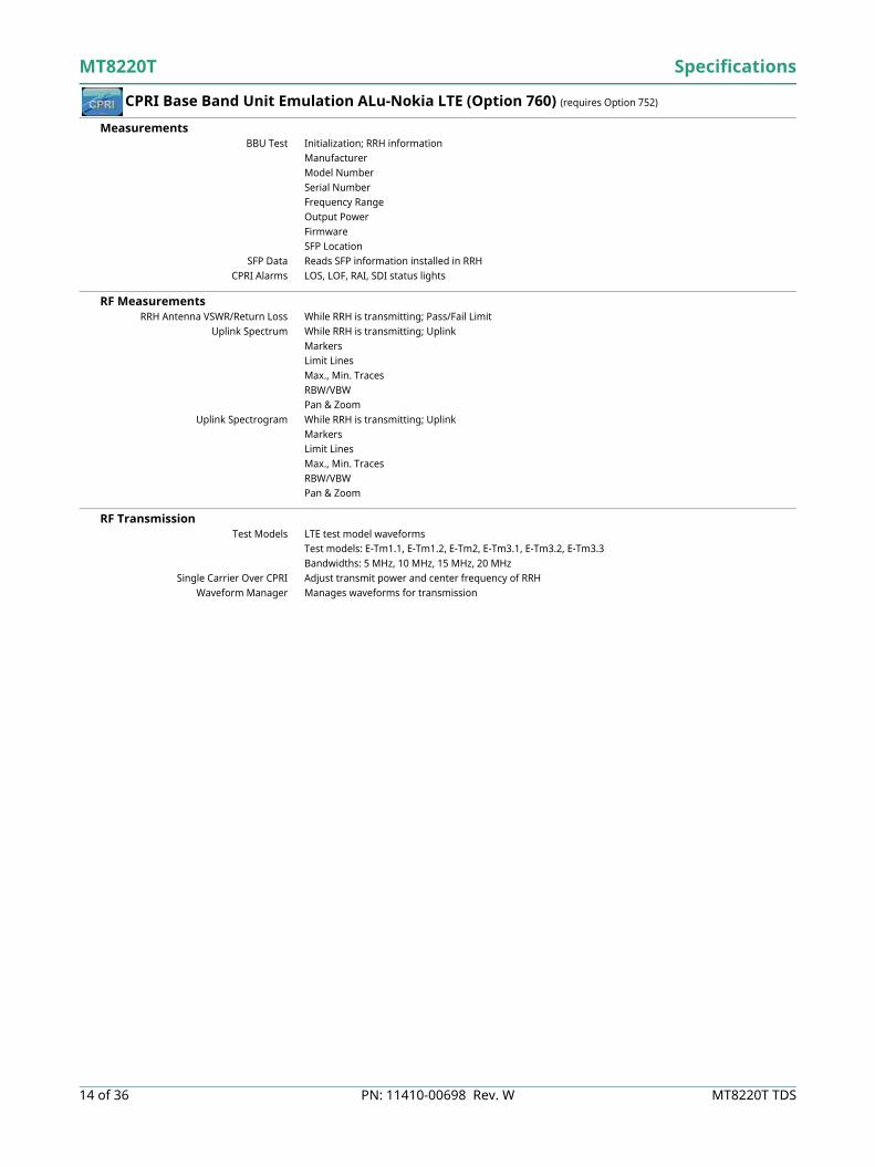
CPRI Base Band Unit Emulation ALu-Nokia LTE (Option 760) (requires Option 752)
Measurements BBU Test Initialization; RRH information
ManufacturerModel NumberSerial NumberFrequency RangeOutput PowerFirmwareSFP Location
SFP Data Reads SFP information installed in RRHCPRI Alarms LOS, LOF, RAI, SDI status lights
RF Measurements RRH Antenna VSWR/Return Loss While RRH is transmitting; Pass/Fail Limit
Uplink Spectrum While RRH is transmitting; UplinkMarkersLimit LinesMax., Min. TracesRBW/VBW Pan & Zoom
Uplink Spectrogram While RRH is transmitting; UplinkMarkersLimit LinesMax., Min. TracesRBW/VBW Pan & Zoom
RF Transmission Test Models LTE test model waveforms
Test models: E-Tm1.1, E-Tm1.2, E-Tm2, E-Tm3.1, E-Tm3.2, E-Tm3.3Bandwidths: 5 MHz, 10 MHz, 15 MHz, 20 MHz
Single Carrier Over CPRI Adjust transmit power and center frequency of RRHWaveform Manager Manages waveforms for transmission

Specifications MT8220T
MT8220T TDS PN: 11410-00698 Rev. W 15 of 36
Remote Electrical Tilt (RET) Device Test (Option 761) (requires Option 760)
Device Support and Interface Supported Remote Radio Heads ALu-Nokia RRH
RET Device Types Single-antennaMulti-antennaeAntennaTower-Mounted Amplifier (TMA)
Communications Interface Fiber optic connection to RRHSpecification Standards AISG V2.0
AISG ES-RAE V2.2.0
Monitoring and Control Device Search Scans for all RET devices connected to selected RRH
Automatic one-time scan upon entering RET Test modeRetrieves current configuration settings of all detected devices
Device Calibration Sends request to RRH for selected RET device to move through entire tilt rangeReturns Pass/Fail result, with reason for failure
Device Configuration Configuration form pre-loaded with current RET device settingsQuick-entry menu selections available for certain text fieldsSaved user settings are retained when existing devices are found in a subsequent device updateSome configuration settings cannot be permanently saved to RET device (antenna type, tower height, antenna technology, sector position)
Configuration Details Antenna modelAntenna typeOperating bands (preset)Antenna serialBase station IDSector IDInstallation dateInstaller IDMechanical tiltMinimum electrical tiltMaximum electrical tiltElectrical tiltAntenna bearingTower heightAntenna technologySector position
Reporting Generates an output text fileLists current configuration details of all detected devicesSaves report file in test instrument’s internal memory
Device Alarms Queries and displays alarm status of selected RET device: MotorJam, ActuatorJam, NotCalibrated, NotConfigured, HardwareError, ActuatorInterferenceUser-initiated attempt to clear alarms; displays results
Device Self Test Sends request to RRH for RET device to perform self testDisplays results, with list of alarms if any
MT8220T Specifications
16 of 36 PN: 11410-00698 Rev. W MT8220T TDS
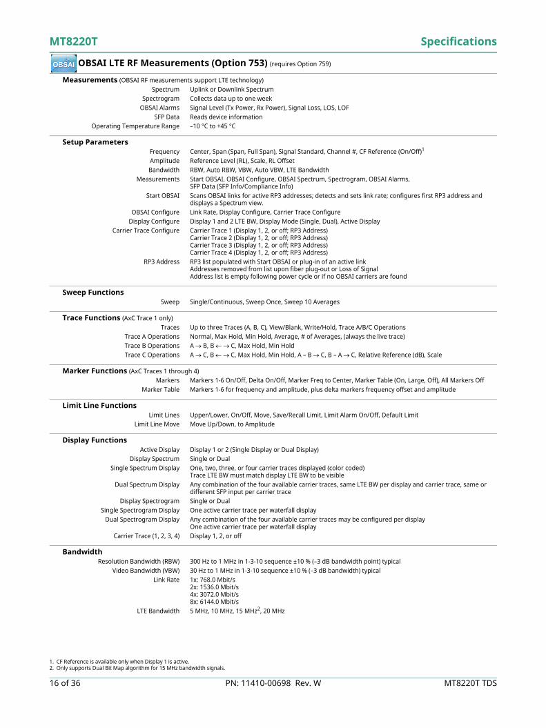
OBSAI LTE RF Measurements (Option 753) (requires Option 759)
Measurements (OBSAI RF measurements support LTE technology)Spectrum Uplink or Downlink Spectrum
Spectrogram Collects data up to one weekOBSAI Alarms Signal Level (Tx Power, Rx Power), Signal Loss, LOS, LOF
SFP Data Reads device informationOperating Temperature Range –10 °C to +45 °C
Setup Parameters Frequency Center, Span (Span, Full Span), Signal Standard, Channel #, CF Reference (On/Off)1
Amplitude Reference Level (RL), Scale, RL OffsetBandwidth RBW, Auto RBW, VBW, Auto VBW, LTE Bandwidth
Measurements Start OBSAI, OBSAI Configure, OBSAI Spectrum, Spectrogram, OBSAI Alarms, SFP Data (SFP Info/Compliance Info)
Start OBSAI Scans OBSAI links for active RP3 addresses; detects and sets link rate; configures first RP3 address and displays a Spectrum view.
OBSAI Configure Link Rate, Display Configure, Carrier Trace ConfigureDisplay Configure Display 1 and 2 LTE BW, Display Mode (Single, Dual), Active Display
Carrier Trace Configure Carrier Trace 1 (Display 1, 2, or off; RP3 Address)Carrier Trace 2 (Display 1, 2, or off; RP3 Address)Carrier Trace 3 (Display 1, 2, or off; RP3 Address)Carrier Trace 4 (Display 1, 2, or off; RP3 Address)
RP3 Address RP3 list populated with Start OBSAI or plug-in of an active linkAddresses removed from list upon fiber plug-out or Loss of SignalAddress list is empty following power cycle or if no OBSAI carriers are found
Sweep Functions Sweep Single/Continuous, Sweep Once, Sweep 10 Averages
Trace Functions (AxC Trace 1 only)Traces Up to three Traces (A, B, C), View/Blank, Write/Hold, Trace A/B/C Operations
Trace A Operations Normal, Max Hold, Min Hold, Average, # of Averages, (always the live trace)Trace B Operations A B, B C, Max Hold, Min HoldTrace C Operations A C, B C, Max Hold, Min Hold, A – B C, B – A C, Relative Reference (dB), Scale
Marker Functions (AxC Traces 1 through 4)Markers Markers 1-6 On/Off, Delta On/Off, Marker Freq to Center, Marker Table (On, Large, Off), All Markers Off
Marker Table Markers 1-6 for frequency and amplitude, plus delta markers frequency offset and amplitude
Limit Line Functions Limit Lines Upper/Lower, On/Off, Move, Save/Recall Limit, Limit Alarm On/Off, Default Limit
Limit Line Move Move Up/Down, to Amplitude
Display Functions Active Display Display 1 or 2 (Single Display or Dual Display)
Display Spectrum Single or DualSingle Spectrum Display One, two, three, or four carrier traces displayed (color coded)
Trace LTE BW must match display LTE BW to be visibleDual Spectrum Display Any combination of the four available carrier traces, same LTE BW per display and carrier trace, same or
different SFP input per carrier traceDisplay Spectrogram Single or Dual
Single Spectrogram Display One active carrier trace per waterfall displayDual Spectrogram Display Any combination of the four available carrier traces may be configured per display
One active carrier trace per waterfall displayCarrier Trace (1, 2, 3, 4) Display 1, 2, or off
Bandwidth Resolution Bandwidth (RBW) 300 Hz to 1 MHz in 1-3-10 sequence ±10 % (–3 dB bandwidth point) typical
Video Bandwidth (VBW) 30 Hz to 1 MHz in 1-3-10 sequence ±10 % (–3 dB bandwidth) typicalLink Rate 1x: 768.0 Mbit/s
2x: 1536.0 Mbit/s4x: 3072.0 Mbit/s8x: 6144.0 Mbit/s
LTE Bandwidth 5 MHz, 10 MHz, 15 MHz2, 20 MHz
1. CF Reference is available only when Display 1 is active.2. Only supports Dual Bit Map algorithm for 15 MHz bandwidth signals.

Specifications MT8220T
MT8220T TDS PN: 11410-00698 Rev. W 17 of 36
GSM/GPRS/EDGE Measurements (Option 880)
Measurements
Setup Parameters GSM/EDGE Select Auto, GSM, EDGE
Frequency Center, Signal Standard, Channel #, Closest Channel, Decrement/Increment ChannelAmplitude Power Offset, Auto Range, Adjust Range
Sweep Single/Continuous, Trigger SweepSave/Recall Setup, Measurement, Screen Shots (JPEG - save only), to Internal/External Memory
Measurement Summary Screen Overall Measurements
RF Measurements Frequency Error ± 10 Hz + time base error, 99 % confidence level
Occupied Bandwidth Bandwidth within which lies 99 % of the power transmitted on a single channelBurst Power Error ± 1.5 dB; ± 1 dB typical (–50 dBm to +20 dBm)
Demodulation Measurements GMSK Modulation Quality (RMS Phase)
Measurement Accuracy ± 1º
Residual Error (GMSK) 1º
8PSK Modulation Quality (EVM)Measurement Accuracy ± 1.5 %
Residual Error (8PSK) 2.5 %
RF Demodulation Over-the-Air (OTA) Pass/FailChannel Spectrum
Channel PowerOccupied BandwidthBurst PowerAverage Burst PowerFrequency ErrorModulation TypeBSIC (NCC, BCC)
Multi-channel SpectrumPower vs. Time (Frame/Slot)
Channel PowerOccupied BandwidthBurst PowerAverage Burst PowerFrequency ErrorModulation TypeBSIC (NCC, BCC)
Phase ErrorEVMOrigin OffsetC/IModulation TypeMagnitude ErrorBSIC (NCC, BCC)
There are no additional OTA MeasurementsRF and Demodulation Measurements can be made OTA
View Pass/Fail Limits GSM, EDGE
Available MeasurementsChannel PowerOccupied BandwidthBurst PowerAverage Burst powerFrequency ErrorPhase ErrorEVMOrigin OffsetC/IMagnitude Error
Script Master™

MT8220T Specifications
18 of 36 PN: 11410-00698 Rev. W MT8220T TDS
W-CDMA/HSPA+ Measurements (Option 881)
Measurements
Setup Parameters Scrambling Code, Threshold Auto, Manual
User Selectable Scrambling Code, S-CCPCH Spread, S-CCPCH Code, PICH Code, Threshold, Max Amp Power, CPICH Power, Frequency Error Average
Maximum Spreading Factor 256, 512Frequency Center, Signal Standard, Channel #, Closest Channel, Decrement/Increment ChannelAmplitude Scale/Division, Power Offset, Auto Range, Adjust Range, Units (dBm/W)
Marker Six Markers, Table On/OffSweep Single/Continuous, Trigger Sweep
Save/Recall Setup, Measurement, Screen Shots (JPEG - save only), to Internal/External MemoryMeasurement Summary Screens Overall Measurements, RF Measurements, Modulation Measurements
RF Measurements RF Channel Power Accuracy ± 1.25 dB; ± 0.7 dB typical (temperature range 15 °C to 35 °C)
Occupied Bandwidth Accuracy ± 100 kHzAdjacent Channel Leakage Ratio (ACLR) –54 dB/-59 dB ± 0.8 dB @ 5 MHz/10 MHz offset, typical, 824 MHz to 894 MHz, 1710 MHz to 2170 MHz
–54 dB/-57 dB ± 1.0 dB @ 5 MHz/10 MHz offset, typical, 2300 MHz to 2700 MHz
Demodulation Measurements W-CDMA Modulations QPSK, QPSK-DTX (Codecs: AMR 4.75, 5.9, 7.4, 12.2 kbps; DTX 7.4, 12.2 kbps)
HSPA+ Modulations QPSK, 16QAM, 64QAMFrequency Error ± 10 Hz + time base error, 99 % confidence level
EVM Accuracy ± 2.5 %, 6 % ≤ EVM ≤ 25 %Residual EVM 2.5 % typical
Code Domain Power ± 0.5 dB for code channel power > –25 dB,16, 32, 64 DCPH (test model 1), 16, 32 DCPH (test model 2, 3)
CPICH (dBm) Accuracy ± 0.8 dB typical
Over-the-Air (OTA) Measurements Scrambling Code Scanner Six strongest Scrambling Codes
Multipath Scanner Multipath power of six signals relative to strongest pilot
RF Demodulation Over-the-Air (OTA) Pass/FailBand SpectrumChannel Spectrum
Channel PowerOccupied BandwidthPeak-to-Average Power
Spectral Emission MaskSingle Carrier ACLRMulti-carrier ACLRRF Summary
Code Domain Power GraphP-CPICH PowerChannel PowerNoise FloorEVMCarrier Feed ThroughPeak Code Domain ErrorCarrier FrequencyFrequency ErrorControl Channel PowerAbs/Rel/Delta Power
CPICH, P-CCPCHS-CCPCH, PICHP-SCH, S-SCH
HSPA+Power vs. TimeConstellation
Code Domain Power TableCode, StatusEVM, Modulation TypePower, Code UtilizationPower Amplifier Capacity
CodogramModulation Summary
Scrambling Code Scanner (Six)Scrambling CodesCPICHEc/IoEcPilot DominanceOTA Total Power
Multipath Scanner (Six)Six MultipathsTauDistanceRSCPRelative PowerMultipath Power
View Pass/Fail Limits All, RF, Demod
Available MeasurementsMax Output PowerFrequency ErrorEVMCPICHOccupied BandwidthSpectral MaskACLRPCDE P-CCPCHS-CCPCHCode Spread 3PICHCode 128
Script Master™ Test Models
1 (16), (32), (64)23 (16), (32)4 (+CPICH), (-CPICH)5 (2 HS), (4 HS), (8 HS)

Specifications MT8220T
MT8220T TDS PN: 11410-00698 Rev. W 19 of 36
TD-SCDMA/HSPA+ Measurements (Option 882)
Measurements
Setup Parameters Slot Selection Auto, 0-6
Trigger Trigger Type (No Trigger/GPS/External), External Trigger (Rising/Falling), Tau OffsetSYNC-DL Code Auto, 0-31
Scrambling/Midamble Code Auto, 0-127Maximum Users Auto, 2, 4, 6, 8, 10, 12, 14, 16
Measurement Speed Fast, Normal, SlowUser Selectable Uplink Switch Point, Number of Carriers (1, 3), Tau Offset
Demodulation Type Auto, QPSK, 8PSK, 16QAM, 64QAMFrequency Center, Signal Standard, Channel #, Closest Channel, Decrement/Increment ChannelAmplitude Scale/Division, Power Offset, Auto Range, Adjust Range, Units (dBm/W)
Sweep Hold/Run, Trigger SweepSave/Recall Setup, Measurement, Screen Shots (JPEG - save only), to Internal/External Memory
Measurement Summary Screens Overall Measurements, RF Measurements, Modulation Measurements
RF Measurements RF Channel Power Accuracy (RRC) ± 1.5 dB; ± 1.0 dB typical, (slot power –40 dBm to +10 dBm)
Frequency Error ± 10 Hz + time base error, in the presence of a downlink slot
Demodulation Measurements Supported Modulation QPSK, 8PSK, 16QAM, 64QAM
Residual EVM (rms) 3 % typical, P-CCPH Slot Power > –50 dBmPN Offset Within 1 × 64 chips
Pilot Power Accuracy ± 1.0 dB typicalTiming Error (Tau) for Dominant SYNC-DL ± 0.2 µs (external trigger)
Spreading Factor 1, 16
Over-the-Air (OTA) Measurements Code Scanner 32 Sync Codes and associated Scrambling Code Groups
Tau Scanner Six strongest Sync CodesAuto Save Yes
GPS Tagging and Logging Yes
RF Demodulation Over-the-Air (OTA) Pass/FailChannel Spectrum
Channel PowerOccupied BandwidthLeft Channel PowerLeft Channel Occ B/WRight Channel PowerRight Channel Occ B/W
Power vs. TimeSix Slot PowersChannel Power (RRC)DL-UL Delta PowerUpPTS PowerDwPTS PowerOn/Off RatioSlot Peak-to-Average Power
Spectral EmissionRF Summary
Code Domain Power/Error(QPSK/8PSK/16QAM/64QAM)Slot PowerDwPTS PowerNoise FloorFrequency ErrorTauScrambling CodeEVMPeak EVMPeak Code Domain ErrorCDP Marker
Modulation Summary
Code Scan (32)Scrambling Code GroupTauEc/IoDwPTS PowerPilot Dominance
Tau Scan (Six)Sync-DL#TauEc/IoDwPTS PowerPilot Dominance
RecordRun/Hold
View Pass/Fail LimitsAll, RF, Demod
Available MeasurementsOccupied BandwidthChannel PowerChannel Power RCCOn/Off RatioPeak-to-Average RatioFrequency ErrorEVMPeak EVMPeak Code Domain ErrorTauNoise Floor

MT8220T Specifications
20 of 36 PN: 11410-00698 Rev. W MT8220T TDS
LTE/LTE-A FDD/TDD Measurements (Options 883 and 886)
LTE/LTE-A FDD Measurements
Setup Parameters Frequency E-UTRA Bands 1 - 14, 17 - 21, 23 - 32, 66A (tunable 10 MHz to 4.0 GHz)
Center, Signal Standard, Channel #, Closest Channel, Decrement/Increment ChannelBandwidth (MHz) 1.4, 3, 5, 10, 15, 20
Span (MHz) Auto, 1.4, 3, 5, 10, 15, 20, 30Amplitude Scale/Division, Power Offset, Auto Range, Adjust Range
Sweep Single/ContinuousEVM Mode Auto, PBCH only, Max Hold
Cyclic Prefix (CP) Auto, Normal, ExtendedSync Type Normal (SS), RS/Cell ID
Save/Recall Setup, Measurement, Screen Shots (JPEG - save only), to Internal/External MemoryMeasurement Summary Screens Overall Measurements, RF Measurements, Modulation Measurements
LTE/LTE-A FDD RF Measurements RF Channel Power Accuracy ± 1.5 dB; ± 1.0 dB typical (RF input –50 dBm to +10 dBm)
LTE/LTE-A FDD Modulation Measurements RS Power Accuracy ± 1.0 dB typical, (RF input –50 dBm to +10 dBm)
Frequency Error ± 10 Hz + time base error, 99 % confidence levelResidual EVM (rms) 2.0 % typical (E-UTRA Test Model 3.1, RF Input –50 dBm to +10 dBm)
LTE/LTE-A FDD Over-the-Air (OTA) Measurements Scanner Six strongest signals if present
Auto Save – Sync Signal power and Modulation Results with GPS information Tx Test Scanner – Three strongest signals if present
RS Power – Strongest Signal Mapping Map On-screen S-SS, RSRP, RSRQ, or SINR of Cell ID with strongest signal
Scanner – three strongest signals if presentSave and Export Mapping data: KML, MTD (tab delimited)
Carrier Aggregation Up to 5 component carriers specified (CC1 to CC5)Automatic detection of CP and MIMO status for each active CCRS Power & RS Delta Power, SS Power, EVM (peak and rms), Freq Error (Hz & ppm), TAE, Cell ID
Evolved Multimedia BroadcastMulticast Services (eMBMS) Reports the Cell ID and measures the Received Signal Received Power (RSRP)
RF Modulation Over-the-Air (OTA) Pass/FailChannel Spectrum
Channel PowerOccupied Bandwidth
ACLRSpectral Emission Mask
Category A or B (Opt 1)RF Summary
Power vs. Resource Block (RB)RB Power (PDSCH)Active RBs, Utilization %Channel Power, Cell IDOSTP, Frame EVM by modulation
ConstellationQPSK, 16QAM, 64QAM256QAM Demod (Option 886)Modulation Results
Ref Signal Power (RS)Sync Signal Power (SS)EVM – rms, peak, max holdFrequency Error – Hz, ppmCarrier FrequencyCell ID
Control Channel PowerBar Graph or Table ViewRS, P-SS, S-SSPBCH, PCFICH, PHICH, PDCCHTotal Power (Table View)EVM per Control Channel
Tx Time AlignmentModulation Summary
Includes EVM by modulationAntenna Icons
Detects active antennas (1 or 2)
ScannerCell ID (Group, Sector)S-SS, RSRP, RSRQ, SINRDominanceModulation Results – On/OffAuto Save - On/Off
Tx TestScannerRS Power of MIMO antennas (2x2, 4x4)Cell ID, Average PowerDelta Power (Max-Min)Graph of Antenna PowerModulation Results – On/Off
MappingOn-screen
S-SS, RSRP, RSRQ, or SINRScanner
Modulation Results – OffCarrier Aggregation
Up to 5 component carriers (CC1 to CC5)CP, MIMO status, RS & SS Power, EVM,Frequency Error, Time Alignment Error,Cell ID
eMBMSCell ID, RSRP
View Pass/Fail LimitsAll, RF, Modulation
Available MeasurementsChannel PowerOccupied BandwidthACLRFrequency ErrorCarrier FrequencyDominanceEVM peak, rmsFrame EVM, rmsFrame EVM by mod typeRS, SS PowerRS EVMP-SS, S-SS, Power, EVMPBCH, PCFICH, PHICH, PDCCH
Power, EVMCell, Group, Sector IDOSTPTx Time Alignment

Specifications MT8220T
MT8220T TDS PN: 11410-00698 Rev. W 21 of 36
LTE/LTE-A FDD/TDD Measurements (Options 883 and 886) (Continued)
LTE/LTE-A TDD Measurements
Setup Parameters Frequency E-UTRA bands 33 - 44 (tunable 10 MHz to 4.0 GHz)
Center, Signal Standard, Channel #, Closest Channel, Decrement/Increment Channel Bandwidth (MHz) 1.4, 3, 5, 10, 15, 20
Span (MHz) Auto, 1.4, 3, 5, 10, 15, 20, 30Amplitude Scale/Division, Power Offset, Auto Range, Adjust Range
Sweep Single/Continuous, Trigger SweepEVM Mode Auto, PBCH only, Max Hold
Cyclic Prefix (CP) Auto, Normal, ExtendedTrigger No Trigger/Ext Trigger, Rising/Falling
Uplink/Downlink Configuration 0 to 6Save/Recall Setup, Measurement, Screen Shots (JPEG - save only), to Internal/External Memory
Measurement Summary Screens Overall Measurements, RF Measurements, Modulation Measurements
LTE/LTE-A TDD RF Measurements RF Channel Power Accuracy ± 1.5 dB; ± 1.0 dB typical (RF input –30 dBm to +10 dBm)
LTE/LTE-A TDD Modulation Measurements RS Power Accuracy ± 1.0 dB typical, (RF input –50 dBm to +10 dBm)
Frequency Error ± 10 Hz + time base error, 99 % confidence level Residual EVM (rms) 2.0 % typical (E-UTRA Test Model 3.1, RF Input –30 dBm to +10 dBm)
LTE/LTE-A TDD Over-the-Air (OTA) Measurements Scanner Six strongest signals if present
Auto Save – Sync Signal power and Modulation Results with GPS informationTx Test Scanner – Three strongest signals if present
RS Power – Strongest Signal Mapping Map On-screen S-SS, RSRP, RSRQ, or SINR of Cell ID with strongest signal
Scanner – three strongest signals if presentSave and Export Mapping data: KML, MTD (tab delimited)
Carrier Aggregation Up to 5 component carriers specified (CC1 to CC5)Automatic detection of CP and MIMO status for each active CCRS Power & RS Delta Power, SS Power, EVM (peak and rms), Freq Error (Hz & ppm), TAE, Cell ID
RF Modulation Over-the-Air (OTA) Pass/FailChannel Spectrum
Channel PowerOccupied Bandwidth
Power vs. TimeFrame ViewSub-Frame ViewTotal Frame PowerDwPTS PowerTransmit Off PowerCell IDTiming Error
ACLRSpectral Emission Mask
Category A or B (Opt 1)RF Summary
Power vs. Resource Block (RB)RB Power (PDSCH)Active RBs, Utilization %Channel Power, Cell IDOSTP, Frame EVM by modulation
ConstellationQPSK, 16QAM, 64QAM256QAM Demod (Option 886)Modulation Results
Ref Signal Power (RS)Sync Signal Power (SS)EVM – rms, peak, max holdFrequency Error – Hz, ppmCarrier FrequencyCell ID
Control Channel PowerBar Graph or Table ViewRS, P-SS, S-SSPBCH, PCFICH, PHICH, PDCCHTotal Power (Table View)EVM per Control Channel
Tx Time AlignmentModulation Summary
Includes EVM by modulationAntenna Icons
Detects active antennas (1/2)
ScannerCell ID (Group, Sector)S-SS, RSRP, RSRQ, SINRDominanceModulation Results – On/OffAuto Save - On/Off
Tx TestScannerRS Power of MIMO antennas (2x2, 4x4)Cell ID, Average PowerDelta Power (Max-Min)Graph of Antenna PowerModulation Results – On/Off
MappingOn-screen
S-SS, RSRP, RSRQ, or SINRScanner
Modulation Results – OffCarrier Aggregation
Up to 5 component carriers (CC1 to CC5)CP, MIMO status, RS & SS Power, EVM,Frequency Error, Time Alignment Error,Cell ID
View Pass/Fail LimitsAll, RF, Modulation
Available MeasurementsChannel PowerOccupied BandwidthACLRFrequency ErrorCarrier FrequencyDominanceEVM peak, rmsFrame EVM, rmsFrame EVM by mod typeRS, SS PowerRS EVMP-SS, S-SS, Power, EVMPBCH, PCFICH, PHICH, PDCCH
Power, EVMCell, Group, Sector IDOSTPTx Time AlignmentFrame PowerDwPTS PowerTransmit Off PowerTiming Error
MT8220T Specifications
22 of 36 PN: 11410-00698 Rev. W MT8220T TDS
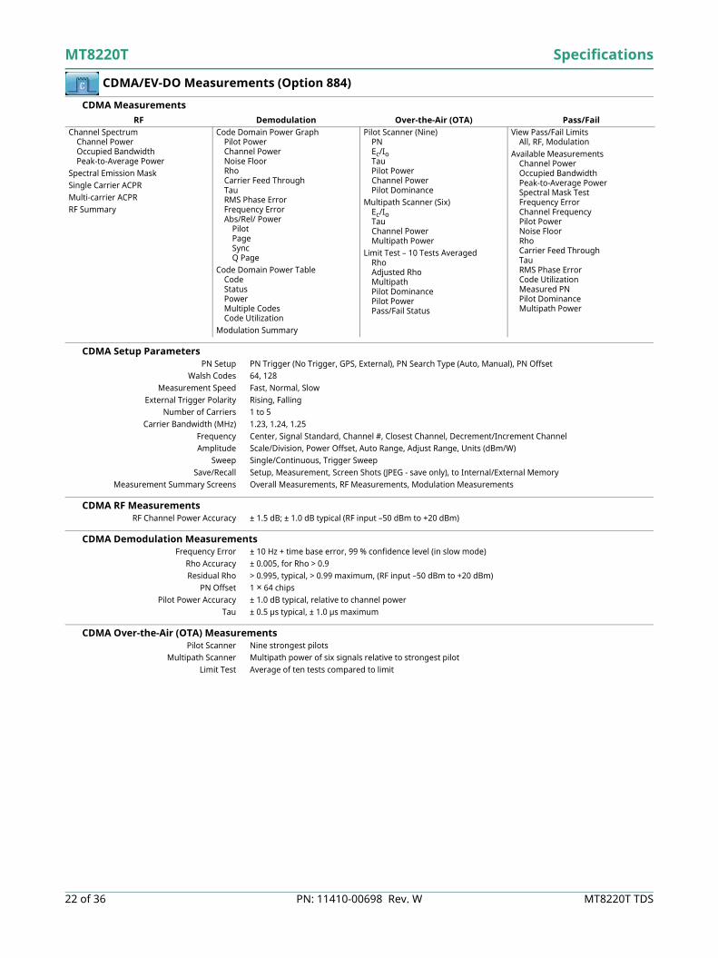
CDMA/EV-DO Measurements (Option 884)
CDMA Measurements
CDMA Setup Parameters PN Setup PN Trigger (No Trigger, GPS, External), PN Search Type (Auto, Manual), PN Offset
Walsh Codes 64, 128Measurement Speed Fast, Normal, Slow
External Trigger Polarity Rising, FallingNumber of Carriers 1 to 5
Carrier Bandwidth (MHz) 1.23, 1.24, 1.25Frequency Center, Signal Standard, Channel #, Closest Channel, Decrement/Increment ChannelAmplitude Scale/Division, Power Offset, Auto Range, Adjust Range, Units (dBm/W)
Sweep Single/Continuous, Trigger SweepSave/Recall Setup, Measurement, Screen Shots (JPEG - save only), to Internal/External Memory
Measurement Summary Screens Overall Measurements, RF Measurements, Modulation Measurements
CDMA RF Measurements RF Channel Power Accuracy ± 1.5 dB; ± 1.0 dB typical (RF input –50 dBm to +20 dBm)
CDMA Demodulation Measurements Frequency Error ± 10 Hz + time base error, 99 % confidence level (in slow mode)
Rho Accuracy ± 0.005, for Rho > 0.9Residual Rho > 0.995, typical, > 0.99 maximum, (RF input –50 dBm to +20 dBm)
PN Offset 1 × 64 chipsPilot Power Accuracy ± 1.0 dB typical, relative to channel power
Tau ± 0.5 µs typical, ± 1.0 µs maximum
CDMA Over-the-Air (OTA) Measurements Pilot Scanner Nine strongest pilots
Multipath Scanner Multipath power of six signals relative to strongest pilotLimit Test Average of ten tests compared to limit
RF Demodulation Over-the-Air (OTA) Pass/FailChannel Spectrum
Channel PowerOccupied BandwidthPeak-to-Average Power
Spectral Emission MaskSingle Carrier ACPRMulti-carrier ACPRRF Summary
Code Domain Power GraphPilot PowerChannel PowerNoise FloorRhoCarrier Feed ThroughTauRMS Phase ErrorFrequency ErrorAbs/Rel/ Power
PilotPageSyncQ Page
Code Domain Power TableCodeStatusPowerMultiple CodesCode Utilization
Modulation Summary
Pilot Scanner (Nine)PNEc/IoTauPilot PowerChannel PowerPilot Dominance
Multipath Scanner (Six)Ec/IoTauChannel PowerMultipath Power
Limit Test – 10 Tests AveragedRhoAdjusted RhoMultipathPilot DominancePilot PowerPass/Fail Status
View Pass/Fail LimitsAll, RF, Modulation
Available MeasurementsChannel PowerOccupied BandwidthPeak-to-Average PowerSpectral Mask TestFrequency ErrorChannel FrequencyPilot PowerNoise FloorRhoCarrier Feed ThroughTauRMS Phase ErrorCode UtilizationMeasured PNPilot DominanceMultipath Power

Specifications MT8220T
MT8220T TDS PN: 11410-00698 Rev. W 23 of 36
CDMA/EV-DO Measurements (Option 884) (continued)
EV-DO Measurements
Setup Parameters PN Setup PN Trigger (No Trigger, GPS, External), PN Search Type (Auto, Manual), PN Offset
Walsh Codes 64, 128Measurement Speed Fast, Normal, Slow
External Trigger Polarity Rising, FallingSlot Type Auto, Active, Idle
Number of Carriers 1 to 5 Carrier Bandwidth (MHz) 1.23, 1.24, 1.25
Frequency Center, Signal Standard, Channel #, Closest Channel, Decrement/Increment ChannelAmplitude Scale/Division, Power Offset, Auto Range, Adjust Range, Units (dBm/W)
Sweep Single/Continuous, Trigger SweepSave/Recall Setup, Measurement, Screen Shots (JPEG - save only), to Internal/External Memory
Measurement Summary Screens Overall Measurements, RF Measurements, Modulation Measurements
EV-DO RF Measurements RF Channel Power Accuracy ± 1.5 dB; ± 1.0 dB typical (RF input –50 dBm to +20 dBm)
EV-DO Demodulation Measurements EV-DO Compatibility Rev 0 and Rev A
Frequency Error ± 10 Hz + time base error, 99 % confidence levelRho Accuracy ± 0.01, for Rho > 0.9Residual Rho > 0.995 typical, > 0.99, maximum (RF input –50 dBm to +20 dBm)
PN Offset Within 1 × 64 chipsPilot Power Accuracy ± 1.0 dB typical, relative to channel power
Tau ± 0.5 µs typical, ± 1.0 µs maximum
EV-DO Over-the-Air (OTA) Measurements Pilot Scanner Nine strongest pilots
Multipath Scanner Multipath power of six signals relative to strongest pilot
RF Demodulation Over-the-Air (OTA) Pass/FailChannel Spectrum
Channel PowerOccupied BandwidthPeak-to-Average Power
Power vs. TimePilot & MAC PowerChannel PowerFrequency ErrorIdle ActivityOn/Off Ratio
Spectral Emission MaskSingle Carrier ACPRMulti-carrier ACPRRF Summary
MAC Code Domain Power GraphPilot & MAC PowerChannel PowerFrequency ErrorRho PilotRho OverallData ModulationNoise Floor
MAC Code Domain Power TableCodeStatusPowerCode Utilization
Data Code Domain PowerActive Data PowerData ModulationRho PilotRho OverallMaximum Data CDPMinimum Data CDP
Modulation Summary
Pilot Scanner (Nine)PNEc/IoTauPilot PowerChannel PowerPilot Dominance
Mulitpath Scanner (Six)Ec/IoTauChannel PowerMultipath Power
View Pass/Fail LimitsAll, RF, Modulation
Available MeasurementsChannel PowerOccupied BandwidthPeak-to-Average PowerCarrier FrequencyFrequency ErrorSpectral MaskNoise FloorPilot PowerRMS Phase ErrorTauCode UtilizationMeasured PNPilot DominanceMulitpath Power
MT8220T Specifications
24 of 36 PN: 11410-00698 Rev. W MT8220T TDS
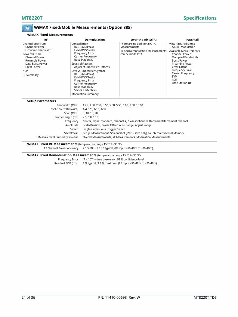
WiMAX Fixed/Mobile Measurements (Option 885)
WiMAX Fixed Measurements
Setup Parameters Bandwidth (MHz) 1.25, 1.50, 2.50, 3.50, 5.00, 5.50, 6.00, 7.00, 10.00
Cyclic Prefix Ratio (CP) 1/4, 1/8, 1/16, 1/32Span (MHz) 5, 10, 15, 20
Frame Length (ms) 2.5, 5.0, 10.0Frequency Center, Signal Standard, Channel #, Closest Channel, Decrement/Increment ChannelAmplitude Scale/Division, Power Offset, Auto Range, Adjust Range
Sweep Single/Continuous, Trigger SweepSave/Recall Setup, Measurement, Screen Shot (JPEG - save only), to Internal/External Memory
Measurement Summary Screens Overall Measurements, RF Measurements, Modulation Measurements
WiMAX Fixed RF Measurements (temperature range 15 °C to 35 °C)RF Channel Power Accuracy ± 1.5 dB; ± 1.0 dB typical, (RF input –50 dBm to +20 dBm)
WiMAX Fixed Demodulation Measurements (temperature range 15 °C to 35 °C)Frequency Error 7 × 10⁻⁸ + time base error, 99 % confidence level
Residual EVM (rms) 3 % typical, 3.5 % maximum (RF Input –50 dBm to +20 dBm)
RF Demodulation Over-the-Air (OTA) Pass/FailChannel Spectrum
Channel PowerOccupied Bandwidth
Power vs. TimeChannel PowerPreamble PowerData Burst PowerCrest Factor
ACPRRF Summary
ConstellationRCE (RMS/Peak)EVM (RMS/Peak)Frequency ErrorCarrier FrequencyBase Station ID
Spectral FlatnessAdjacent Subcarrier Flatness
EVM vs. Subcarrier/SymbolRCE (RMS/Peak)EVM (RMS/Peak)Frequency ErrorCarrier FrequencyBase Station IDSector ID (Mobile)
Modulation Summary
There are no additional OTA MeasurementsRF and Demodulation Measurements can be made OTA
View Pass/Fail LimitsAll, RF, Modulation
Available MeasurementsChannel PowerOccupied BandwidthBurst PowerPreamble PowerCrest FactorFrequency ErrorCarrier FrequencyEVMRCEBase Station ID

Specifications MT8220T
MT8220T TDS PN: 11410-00698 Rev. W 25 of 36
WiMAX Fixed/Mobile Measurements (Option 885) (continued)
WiMAX Mobile1 Measurements
Setup Parameters Zone Type PUSC
DL-MAP Auto Decoding Convolutional Coding (CC), Convolutional Turbo Coding (CTC) Bandwidths (MHz) 3.50, 5.00, 7.00, 8.75, 10.00
Cyclic Prefix Ratio (CP) 1/8 Span (MHz) 5, 10, 20, 30
Frame Lengths (ms) 5, 10Demodulation Auto, Manual, FCH
Frequency Center, Signal Standard, Channel #, Closest Channel, Decrement/Increment ChannelAmplitude Scale/Division, Power Offset, Auto Range, Adjust Range
Sweep Single/Continuous, Trigger SweepSave/Recall Setup, Measurement, Screen Shot (JPEG - save only), to Internal/External Memory
Measurement Summary Screens Overall Measurements, RF Measurements, Modulation Measurements
WiMAX Mobile RF Measurements (temperature range 15 °C to 35 °C)RF Channel Power Accuracy ± 1.5 dB; ± 1.0 dB typical, (RF input –50 dBm to +20 dBm)
WiMAX Mobile Demodulation Measurements (temperature range 15 °C to 35 °C)Frequency Error 2 × 10⁻⁸ + time base error, 99 % confidence level
Residual EVM (rms) 2.5 % typical, 3.0 % maximum (RF Input –50 dBm to +20 dBm)
WiMAX Mobile Over-the-Air (OTA) Measurements Channel Power Monitor Over time (one week), measurement time interval 1 s to 60 s
Preamble Scanner Six strongest PreamblesAuto Save Yes
GPS Tagging and Logging Yes
1. Mobile WiMAX conforms to IEEE Std. 802.16e-2005, WiMAX Forum® Air Interface - Mobile System Profile - Release 1.0 Certified, System Profiles according to WMF-T24-001-R010v07
RF Demodulation Over-the-Air (OTA) Pass/FailChannel Spectrum
Channel PowerOccupied Bandwidth
Power vs. TimeChannel PowerPreamble PowerDownlink Burst PowerUplink Burst Power
ACPRSpectral Emission MaskRF Summary
ConstellationRCE (RMS/Peak)EVM (RMS/Peak)Frequency ErrorCINRBase Station IDSector ID
Spectral FlatnessAdjacent Subcarrier Flatness
EVM vs. Subcarrier/SymbolRCE (RMS/Peak)EVM (RMS/Peak)Frequency ErrorCINRBase Station IDSector ID
DL-MAP (Tree View)Modulation Summary
Channel Power MonitorPreamble Scanner (Six)
PreambleRelative PowerCell IDSector IDPCINRDominant Preamble
Base Station IDAuto Save - On/Off
View Pass/Fail LimitsAll, RF, Modulation
Available MeasurementsChannel PowerOccupied BandwidthDownlink Burst PowerUplink Burst PowerPreamble PowerCrest FactorFrequency ErrorCarrier FrequencyEVMRCESector ID

MT8220T Specifications
26 of 36 PN: 11410-00698 Rev. W MT8220T TDS
General Specifications
Setup Parameters System Status (Temperature, Battery Info, Serial Number, Firmware Version, Options Installed)
Self Test, Application Self Test, GPSSystem Options Name, Date and Time, Ethernet Configuration, Volume,
Display (Brightness, Blank, Default, Black & White, Night Vision, High Contrast, Invert Black & White)Share Center Frequency and Power Offset (All Modes or Not Shared)Language (English, French, German, Spanish, Chinese, Japanese, Korean, Italian, Russian, User defined)Reset (Factory Defaults, Master Reset, Update Firmware)
File Save As, Save Meas, Save, Save On Event, Recall Meas, Recall, Copy, DeleteSave/Recall Setups, Measurements, Screen Shots (JPEG - save only)
Delete By File Type, All, SelectedInternal Trace/Setup Memory > 30,000 tracesExternal Trace/Setup Memory Limited by size of USB Flash drive
Mode Switching Auto-Stores/Recalls most recently used Setup Parameters in the Mode
Connectors RF Out Type N, female, 50 Ω, Maximum Input +23 dBm, ± 50 VDC, (Reflection In)
RF In Type N, female, 50 Ω, Maximum Input +30 dBm, ± 50 VDCGPS SMA, female
External Power 5.5 mm barrel connector, 12 VDC to 14.5 VDC, < 5.0 ALAN Connection RJ48C, 10/100 Mbps, Connect to PC or LAN for Remote Access
USB Interface Two Type A, Connect Flash Drive and Power SensorOne 5-pin mini-B, Connect to PC for data transfer
Headset Jack 3.5 mm 3-wire headset jackExternal Reference In BNC, female, 50 Ω, Maximum Input +10 dB
Reference Out BNC, female, 50 Ω, 10 MHzExternal Trigger In BNC, female, 50 Ω style, 100 kΩ input impedance (nominal), TTL levels, Maximum Input ± 5 VDC
IF Out BNC, female, 50 Ω, 140 MHzRF over Fiber SFP/SFP+ compatible sockets (available with Option 759)
Display and Keyboard Display 8.4 inch touchscreen, 800 x 600 resolution
Pixel Defects No more than five defective pixels (99.9989% good pixels)Keyboard Backlit (Red for Night Vision, White for all other display modes)
Battery Type Li-IonBattery Operation 2.5 hours, typical
Battery Charging Limits 0 °C to +45 °C, Relative Humidity ≤ 80 %
Regulatory Compliance European Union EMC 2014/30/EU, EN 61326:2013, CISPR 11/EN 55011, IEC/EN 61000-4-2/3/4/5/6/8/11
Low Voltage Directive 2014/35/EUSafety EN 61010-1:2010RoHS Directive 2011/65/EU applies to instruments with CE marking placed on the market after July 22, 2017
Australia and New Zealand RCM AS/NZS 4417:2012South Korea KCC-REM-A21-0004
Environmental MIL-PRF-28800F Class 2Operating Temperature Range –10 ºC to 55 ºC
Storage Temperature Range –51 ºC to 71 ºCMaximum Relative Humidity 95 % RH at 30 ºC, non-condensing
Vibration, Sinusoidal 5 Hz to 55 HzVibration, Random 10 Hz to 500 Hz
Half Sine Shock 30 gnAltitude 4600 meters, operating and non-operating
Explosive Atmosphere MIL-PRF-28800F Section 4.5.6.3MIL-STD-810G, Method 511.5, Procedure 1
Size and Weight Size 315 mm x 211 mm x 102 mm (12.4 in x 8.3 in x 4.0 in)
Weight 4.7 kg (10.3 lb)
Warranty Duration Standard three-year warranty
One-year warranty on battery

Specifications MT8220T
MT8220T TDS PN: 11410-00698 Rev. W 27 of 36
Line Sweep Tools™ (for your PC)
Trace Capture Browse to Instrument View and copy traces from the test equipment to your PC using Windows Explorer
Open Legacy Files Open DAT files captured with Handheld Software Tools v6.61Open Current Files Open VNA or DAT files
Capture Plots To The Line Sweep Tools screen, DAT files, Database, or JPEG
Traces Trace Types Return Loss, VSWR, DTF-RL, DTF-VSWR, Cable Loss, Smith Chart, and PIM
Trace Formats DAT, VNA, CSV, PNG, BMP, JPG, HTML, Data Base, and PDF
Report Generation Report Generator Includes GPS location along with measurements
Report Format Create reports in HTML or PDF formatReport Setup Report Title, Company, Prepared for, Location, Date and Time, Filename, Company logo
Trace Setup 1 Trace Portrait Mode, 2 Trace Portrait Mode, 1 Trace Landscape Mode
Trace Validation Presets 7 presets allow “one click” setting of up to 6 markers and one limit line
Marker Controls 6 regular Markers, Marker Peak, Marker Valley, Marker between, and frequency entryDelta Markers 6 Delta markers
Limit Line Enable and drag or value entry. Also works with presetsNext Trace Button Next Trace and Previous Trace arrow keys allow quick switching between traces
Tools Cable Editor Allows creation of custom cable parameters
Distance to Fault Converts a Return Loss trace to a Distance to Fault traceMeasurement Calculator Converts Real, Imaginary, Magnitude, Phase, RL, VSWR, Rho, and Transmit power
Signal Standard Editor Creates new band and channel tablesRenaming Grid 36 user definable phrases for creation of file names, trace titles, and trace subtitles
Connectivity Connections Ethernet, USB cable, and USB memory stick
Master Software Tools™ (for your PC)
Mapping (GPS required)Spectrum Analyzer Mode MapInfo, MapPoint
Mobile WiMAX OTA, LTE OTA Options Google Earth, Google Maps, MapInfo
Folder Spectrogram (Spectrum Monitoring for Interference Analysis and Spectrum Clearing)Folder Spectrogram – 2D View Creates a composite file of multiple traces
Peak Power, Total Power, Peak Frequency, Histogram, Average Power (Max/Min)File Filter (Violations over limit lines or deviations from averages)Playback
Video Folder Spectrogram – 2D View Create AVI file to export for management review/reportsFolder Spectrogram – 3D View Views (Set Threshold, Markers)
- 3D (Rotate X, Y, Z Axis, Level Scale, Signal ID) - 2D View (Frequency or Time Domain, Signal ID) - Top DownPlayback (Frequency and/or Time Domain)
List/Parameter Editors Traces Add, delete, and modify limit lines and markers
Product Updates Auto-checks Anritsu website for latest revision firmwarePass/Fail Create, download, or edit Signal Analysis Pass/Fail Limits
Languages Add custom language or modify non-English language menus
Script Master™ Channel Scanner Mode Automate scan up to 1200 channels, repeat for sets of 20 channels, repeat all channels
GSM/GPRS/EDGE or W-CDMA/HSPA+ Mode Automate Signal Analysis testing requirements with annotated how-to pictures
Connectivity Connections Connect to PC using USB or Ethernet

MT8220T Specifications
28 of 36 PN: 11410-00698 Rev. W MT8220T TDS
easyMap Tools™ (for your PC)
Outdoor Maps On-Line Sources Google Maps, Cloud Made Open-Source Maps
Pan & Zoom Mode AZM map file format allows pan and zoom on-instrumentLegacy Mode MAP format is compatible with older firmware
Geo-Referenced Works with instrument based GPSMap Conversion Convert scanned maps to geo-referenced
Indoor Maps Sources Scanned images in JPG, JPEG, JPE, JFIF, GIF, TIF, TIFF, PNG
General Color Filter Grayscale, High Contrast
Coverage Worldwide Zoom Levels 16 total zoom levels, 7 available in any one map
Map Size Less than 1 MB to over 1 GB
Web Remote Control
Control Full instrument control through a browser – all instrument functions except power switch and rotary knob
Connections RJ45 Ethernet jackThird party Wi-Fi router
Protocol HTTP/TCP/IPPhysical Layer Cat 5 Cable, Wi-Fi router compatible
Software Required HTML 5 Compliant Browser – Newer versions of Chrome, Firefox, Internet Explorer and othersOperating System iOS, Windows, Linux, Android operating systems that can host the HTML 5 Compliant browserRemote Hardware PCs, Tablets, and Smart Phones with Ethernet or Wi-Fi connections and a HTML 5 Compliant browser
Download Individual instrument files downloaded via browserMultiple instrument files and directories zipped and downloaded via browserScreen capture capability
Display Modes Normal: All modes & displays supportedFast: Spectrum traces update faster (up to 5 updates per second)
Password The instrument can be password protectedPasswords may be used to manage who is controlling the instrument
Users/Instruments One user/device can view and control many instruments
Programmable Remote Control
Functionality Many instrument functions are programmable. See the Programming Manual for details.
Programming Language Standard Commands for Programmable Instruments (SCPI)Interfaces USB, LAN
Available Drivers LabView (visit NI.com for driver)

Specifications MT8220T
MT8220T TDS PN: 11410-00698 Rev. W 29 of 36
Ordering Information – Instrument Options
MT8220T Description
400 MHz to 6 GHz Cable and Antenna Analyzer
150 kHz to 7.1 GHz Spectrum Analyzer
10 MHz to 7.1 GHz Power Meter
Options
MT8220T-0010 Bias-Tee
MT8220T-0019 High-Accuracy Power Meter (requires external power sensor)
MT8220T-0025 Interference Analyzer
MT8220T-0027 Channel Scanner
MT8220T-0089 Zero-Span IF Output
MT8220T-0431 Coverage Mapping
MT8220T-0090 Gated Sweep
MT8220T-0024 I/Q Waveform Capture
MT8220T-0023 Vector Signal Generator
MT8220T-0752 CPRI LTE RF Measurements (requires Option 759)
MT8220T-0760 CPRI BBU Emulation ALu-Nokia LTE (requires Option 752)
MT8220T-0761 RET Device Test ALu-Nokia (requires Option 760)
MT8220T-0753 OBSAI LTE RF Measurements (requires Option 759)
MT8220T-0759 RF over Fiber hardware (requires Option 752 or 753)
MT8220T-0880 GSM/GPRS/EDGE Measurements
MT8220T-0881 W-CDMA/HSPA+ Measurements
MT8220T-0882 TD-SCDMA/HSPA+ Measurements
MT8220T-0883 LTE/LTE-A FDD/TDD Measurements
MT8220T-0886 LTE 256QAM Demodulation (Requires Option 883)
MT8220T-0884 CDMA/EV-DO Measurements
MT8220T-0885 WiMAX Fixed/Mobile Measurements
MT8220T-0098 Standard Calibration to ISO/IEC 17025
MT8220T-0099 Premium Calibration to ISO/IEC 17025 plus test data

MT8220T Specifications
30 of 36 PN: 11410-00698 Rev. W MT8220T TDS
Standard Accessories (included with instrument)
Manuals (Soft copy at www.anritsu.com)
Troubleshooting Guides (soft copy at www.anritsu.com)
Power Sensors (for complete ordering information, see the respective data sheets of each sensor)
Part Number Description2000-1686-R Soft Carrying Case2000-1760-R GPS Antenna, SMA(m), 25 dB gain, 2.5 VDC to 3.7 VDC2000-1691-R Stylus with Coiled Tether
633-75 Rechargeable Li-Ion Battery, 7500 mAh40-187-R AC/DC Power Supply
806-141-R Automotive Power Adapter, 12 VDC, 60 Watts2000-1371-R Ethernet Cable, 213 cm (7 ft)3-2000-1498 USB A-mini B Cable, 305 cm (10 ft)
Certificate of Calibration
Part Number Description10580-00366 BTS Master User Guide10580-00230 Cable and Antenna Analyzer Measurement Guide10580-00349 Spectrum Analyzer Measurement Guide10580-00240 Power Meter Measurement Guide10580-00232 Vector Signal Generator Measurement Guide10580-00234 3GPP Signal Analyzer Measurement Guide10580-00235 3GPP2 Signal Analyzer Measurement Guide10580-00236 WiMAX Signal Analyzer Measurement Guide10580-00415 CPRI RF Analyzer and BBU Emulator Measurement Guide10580-00434 OBSAI RF Analyzer Measurement Guide10580-00367 Programming Manual10580-00368 Maintenance Manual
Part Number Description11410-00473 Cable, Antenna and Components11410-00551 Spectrum Analyzers11410-00472 Interference11410-00566 LTE eNodeB Base Stations11410-00615 TD-LTE eNodeB Base Stations11410-00466 GSM/GPRS/EDGE Base Stations11410-00463 W-CDMA/HSDPA Base Stations11410-00465 TD-SCDMA/HSDPA Base Stations11410-00467 cdmaOne/CDMA2000 1X Base Stations11410-00468 CDMA2000 1xEV-DO Base Stations11410-00470 Fixed WiMAX Base Stations11410-00469 Mobile WiMAX Base Stations
Part Number DescriptionPSN50 High Accuracy RF Power Sensor, 50 MHz to 6 GHz, +20 dBm
MA24105A Inline Peak Power Sensor, 350 MHz to 4 GHz, +51.76 dBmMA24106A High Accuracy RF Power Sensor, 50 MHz to 6 GHz, +23 dBmMA24108A Microwave USB Power Sensor, 10 MHz to 8 GHz, +20 dBmMA24118A Microwave USB Power Sensor, 10 MHz to 18 GHz, +20 dBmMA24126A Microwave USB Power Sensor, 10 MHz to 26 GHz, +20 dBmMA24208A Microwave Universal USB Power Sensor,
10 MHz to 8 GHz, +20 dBm to –60 dBmMA24218A Microwave Universal USB Power Sensor,
10 MHz to 18 GHz, +20 dBm to –60 dBmMA24330A Microwave CW USB Power Sensor, 10 MHz to 33 GHz, +20 dBmMA24340A Microwave CW USB Power Sensor, 10 MHz to 40 GHz, +20 dBmMA24350A Microwave CW USB Power Sensor, 10 MHz to 50 GHz, +20 dBmMA25100A RF Power Indicator

Specifications MT8220T
MT8220T TDS PN: 11410-00698 Rev. W 31 of 36
Optional Accessories
Calibration Components, 50 Ω
Calibration Components, 75 Ω
Adapters
Precision Adapters
Part Number Description
OSLN50A-8 High Performance Type N(m), DC to 8 GHz, 50 Ω
OSLNF50A-8 High Performance Type N(f), DC to 8 GHz, 50 Ω
2000-1914-R Precision Open/Short/Load, 4.3-10(f), DC to 6 GHz, 50 Ω
2000-1915-R Precision Open/Short/Load, 4.3-10(m), DC to 6 GHz, 50 Ω
2000-1618-R Precision Open/Short/Load, 7/16 DIN(m), DC to 6.0 GHz 50
2000-1619-R Precision Open/Short/Load, 7/16 DIN(f), DC to 6.0 GHz 50
22N50 Open/Short, N(m), DC to 18 GHz, 50
22NF50 Open/Short, N(f), DC to 18 GHz, 50
SM/PL-1 Precision Load, N(m), 42 dB, 6.0 GHz
SM/PLNF-1 Precision Load, N(f), 42 dB, 6.0 GHz
Part Number Description22N75 Open/Short, N(m), DC to 3 GHz, 75 Ω
22NF75 Open/Short, N(f), DC to 3 GHz, 75 Ω26N75A Precision Termination, N(m), DC to 3 GHz, 75 Ω
26NF75A Precision Termination, N(f), DC to 3 GHz, 75 Ω
12N50-75B Matching Pad, DC to 3 GHz, 50 Ω to 75 Ω
Part Number Description1091-417-R N(m) to QMA(f), DC to 6 GHz, 50 Ω1091-418-R N(m) to QMA(m), DC to 18 GHz, 50 Ω
Part Number Description
34NN50A N(m) to N(m), DC to 18 GHz, 50 Ω
34NFNF50 N(f) to N(f), DC to 18 GHz, 50 Ω
1091-26-R SMA(m) to N(m), DC to 18 GHz, 50 Ω
1091-27-R SMA(f) to N(m), DC to 18 GHz, 50 Ω
1091-80-R SMA(m) to N(f), DC to 18 GHz, 50 Ω
1091-81-R SMA(f) to N(f), DC to 18 GHz, 50 Ω
1091-172-R BNC(f) to N(m), DC to 1.3 GHz, 50 Ω
1091-465-R Adapter, DC to 6 GHz, 4.3-10(f) to N(f), 50 Ω
1091-467-R Adapter, DC to 6 GHz, 4.3-10(m) to N(f), 50 Ω
510-90-R 7/16 DIN(f) to N(m), DC to 7.5 GHz, 50 Ω
510-91-R 7/16 DIN(f) to N(f), DC to 7.5 GHz, 50 Ω
510-92-R 7/16 DIN(m) to N(m), DC to 7.5 GHz, 50 Ω
510-93-R 7/16 DIN(m) to N(f), DC to 7.5 GHz, 50 Ω
510-96-R 7/16 DIN(m) to 7/16 DIN (m), DC to 7.5 GHz, 50 Ω
510-97-R 7/16 DIN(f) to 7/16 DIN (f), DC to 7.5 GHz, 50 Ω
510-102-R N(m) to N(m), DC to 11 GHz, 50 Ω, 90 degrees right angle

MT8220T Specifications
32 of 36 PN: 11410-00698 Rev. W MT8220T TDS
Optional Accessories (Continued)
InterChangeable Adaptor Phase Stable Test Port Cables, Armored w/Reinforced Grip (recommended for cable and antenna line sweep applications. It uses the same ruggedized grip as the Reinforced grip series cables. Now you can also change the adaptor interface on the grip to four different connector types)
Phase-Stable Test Port Cables, Armored w/ Reinforced Grip (Recommended for cable & antenna line sweep applications)
Phase-Stable Test Port Cables, Armored (ideal for use with tightly spaced connectors and other general use applications)
Miscellaneous Accessories
Part Number Description15RCN50-1.5-R 1.5 m, DC to 6 GHz, N(m), N(f), 7/16 DIN(m), 7/16 DIN(f), 50 Ω15RCN50-3.0-R 3.0 m, DC to 6 GHz, N(m), N(f), 7/16 DIN(m), 7/16 DIN(f), 50 Ω
Part Number Description15RNFN50-1.5-R 1.5 m, DC to 6 GHz, N(m) to N(f), 50 Ω15RDFN50-1.5-R 1.5 m, DC to 6 GHz, N(m) to 7/16 DIN(f), 50 Ω15RDN50-1.5-R 1.5 m, DC to 6 GHz, N(m) to 7/16 DIN(m), 50 Ω
15RNFN50-3.0-R 3.0 m, DC to 6 GHz, N(m) to N(f), 50 Ω15RDFN50-3.0-R 3.0 m, DC to 6 GHz, N(m) to 7/16 DIN(f), 50 Ω15RDN50-3.0-R 3.0 m, DC to 6 GHz, N(m) to 7/16 DIN(m), 50 Ω
Part Number Description15NNF50-1.5C 1.5 m, DC to 6 GHz, N(m) to N(f), 50 Ω15NN50-1.5C 1.5 m, DC to 6 GHz, N(m) to N(m), 50 Ω
15NDF50-1.5C 1.5 m, DC to 6 GHz, N(m) to 7/16 DIN(f), 50 Ω15ND50-1.5C 1.5 m, DC to 6 GHz, N(m) to 7/16 DIN(m), 50 Ω
15NNF50-3.0C 3.0 m, DC to 6 GHz, N(m) to N(f), 50 Ω15NN50-3.0C 3.0 m, DC to 6 GHz, N(m) to N(m), 50 Ω
15NNF50-5.0C 5.0 m, DC to 6 GHz, N(m) to N(f), 50 Ω15NN50-5.0C 5.0 m, DC to 6 GHz, N(m) to N(m), 50 Ω
15N43M50-1.5C Test Port Extension Cable, Armored, 1.5 meters, DC to 6GHz, N(m) to 4.3-10(m)
15N43F50-1.5C Test Port Extension Cable, Armored, 1.5 meter, DC to 6GHz, N(m) to 4.3-10(f)
15N43M50-3.0C Test Port Extension Cable, Armored, 3 meters, DC to 6 GHz, N(m) to 4.3-10(m)
15N43F50-3.0C Test Port Extension Cable, Armored, 3 meters, DC to 6 GHz, N(m) to 4.3-10(f)
15NF43M50-1.5C Test Port Extension Cable, Armored, 1.5 meters, DC to 6 GHz, N(f) to 4.3-10(m)
15NF43F50-1.5C Test Port Extension Cable, Armored, 1.5 meters, DC to 6 GHz, N(f) to 4.3-10(f)
15NF43M50-3.0C Test Port Extension Cable, Armored, 3 meters, DC to 6 GHz, N(f) to 4.3-10(m)
15NF43F50-3.0C Test Port Extension Cable, Armored, 3 meters, DC to 6 GHz, N(f) to 4.3-10(f)
Part Number Description2000-1374 External Dual Charger for Li-lon Batteries
633-75 Rechargeable Li-Ion Battery, 7500 mAh2000-1689 EMI Near Field Probe Kit
2000-1797-R Touchscreen Protective Film, 8.4 inMA2700A Handheld Interference Hunter (For full specifications, refer to the MA2700A
Technical Data Sheet 11410-00692)2000-1691-R Stylus with Coiled Tether2000-1798-R Port Extender, DC to 6 GHz, N(m) to N(f)

Specifications MT8220T
MT8220T TDS PN: 11410-00698 Rev. W 33 of 36
Optional Accessories (Continued)
GPS Antennas
Directional Antennas
Portable Antennas
Mag Mount and Broadband Antennas
Part Number Description2000-1528-R GPS Antenna, SMA(m) with 5 m (15 ft) cable, 3 dBi gain, requires 5 VDC2000-1652-R GPS Antenna, SMA(m) with 0.3 m (1 ft) cable, 5 dBi gain, requires 3.3 VDC or
5 VDC2000-1760-R GPS Antenna, SMA(m), 25 dB gain, 2.5 VDC to 3.7 VDC
Part Number Description2000-1411-R 824 MHz to 896 MHz, N(f), 12.3 dBi, Yagi2000-1412-R 885 MHz to 975 MHz, N(f), 12.6 dBi, Yagi2000-1413-R 1710 MHz to 1880 MHz, N(f), 12.3 dBi. Yagi2000-1414-R 1850 MHz to 1990 MHz, N(f), 11.4 dBi, Yagi2000-1415-R 2400 MHz to 2500 MHz, N(f), 14.1 dBi, Yagi2000-1416-R 1920 MHz to 2170 MHz, N(f), 14.3 dBi, Yagi2000-1659-R 698 MHz to 787 MHz, N(f), 10.1 dBi, Yagi2000-1660-R 1425 MHz to 1535 MHz, N(f), 14.3 dBi, Yagi2000-1715-R Directional Antenna, 698 MHz to 2500 MHz, N(f), gain of 2 dBi to 10 dBi,
typical2000-1726-R Antenna, 2500 MHz to 2700 MHz, N(f), 14.1 dBi, Yagi2000-1747-R Antenna, Log Periodic, 300 MHz to 7000 MHz, N(f), 5.1 dBi, typical2000-1748-R Antenna, Log Periodic, 1 GHz to 18 GHz, N(f), 6 dBi, typical2000-1777-R Portable Directional Antenna, 9 kHz to 20 MHz, N(f)2000-1778-R Portable Directional Antenna, 20 MHz to 200 MHz, N(f)2000-1779-R Portable Directional Antenna, 200 MHz to 500 MHz, N(f)2000-1812-R Portable Yagi Antenna, 450 MHz to 512 MHz, N(f), 7.1 dBi2000-1825-R Portable Yagi Antenna, 380 MHz to 430 MHz, N(f), 7.1 dBi
Part Number Description2000-1200-R 806 MHz to 866 MHz, SMA(m), 50 Ω2000-1473-R 870 MHz to 960 MHz, SMA(m), 50 Ω2000-1035-R 896 MHz to 941 MHz, SMA(m), 50 Ω (1/2 wave)2000-1030-R 1710 MHz to 1880 MHz, SMA(m), 50 Ω (1/2 wave)2000-1474-R 1710 MHz to 1880 MHz with knuckle elbow (1/2 wave)2000-1031-R 1850 MHz to 1990 MHz, SMA(m), 50 Ω (1/2 wave)2000-1475-R 1920 MHz to 1980 MHz and 2110 MHz to 2170 MHz, SMA(m), 50 Ω2000-1032-R 2400 MHz to 2500 MHz, SMA(m), 50 Ω (1/2 wave)2000-1361-R 2400 MHz to 2500 MHz and 5000 MHz to 6000 MHz, SMA(m), 50 Ω2000-1636-R Antenna Kit (Consists of: 2000-1030-R, 2000-1031-R, 2000-1032-R,
2000-1200-R, 2000-1035-R, 2000-1361-R, and carrying pouch)2000-1751-R LTE Dipole, 698-960/1710-2170/2500-2700 MHz, SMA(m), 2 dBi, typical, 50
Part Number Description2000-1616-R 20 MHz to 21000 MHz, N(f), 50 Ω2000-1645-R 694 MHz to 894 MHz, 3 dBi peak gain
1700 MHz to 2700 MHz, 3 dBi peak gain, N(m), 50 Ω, 10 ft2000-1646-R 750 MHz to 1250 MHz, 3 dBi peak gain,
1650 MHz to 2000 MHz, 5 dBi peak gain, 2100 MHz to 2700 MHz, 5 dBi peak gain, N(m), 50 Ω, 10 ft
2000-1647-R Cable 1: 698 MHz to 1200 MHz, 2 dBi peak gain, 1700 MHz to 2700 MHz, 5 dBi peak gain, N(m), 50 Ω, 10 ft
Cable 2: 3000 MHz to 6000 MHz, 5 dBi peak gain, N(m), 50 Ω, 10 ft Cable 3: GPS 26 dB gain, SMA(m), 50 Ω, 10 ft
2000-1648-R 1700 MHz to 6000 MHz, 3 dBi peak gain, N(m), 50 Ω, 10 ft

MT8220T Specifications
34 of 36 PN: 11410-00698 Rev. W MT8220T TDS
Optional Accessories (continued)
Filters
Attenuators
Part Number Description
1030-114-R 806 MHz to 869 MHz, N(m) to SMA(f), 50 Ω
1030-109-R 824 MHz to 849 MHz, N(m) to SMA(f), 50 Ω
1030-110-R 880 MHz to 915 MHz, N(m) to SMA(f), 50 Ω
1030-111-R 1850 MHz to 1910 MHz, N(m) to SMA(f), 50 Ω
1030-112-R 2400 MHz to 2484 MHz, N(m) to SMA(f), 50 Ω
1030-105-R 890 MHz to 915 MHz, N(m) to N(f), 50 Ω
1030-106-R 1710 MHz to 1790 MHz, N(m) to N(f), 50 Ω
1030-107-R 1910 MHz to 1990 MHz, N(m) to N(f), 50 Ω
1030-149-R High Pass, 150 MHz, N(m) to N(f), 50 Ω
1030-150-R High Pass, 400 MHz, N(m) to N(f), 50 Ω
1030-151-R High Pass, 700 MHz, N(m) to N(f), 50 Ω
1030-152-R Low Pass, 200 MHz, N(m) to N(f), 50 Ω
1030-153-R Low Pass, 550 MHz, N(m) to N(f), 50 Ω
1030-155-R 2500 MHz to 2700 MHz, N(m) to N(f), 50 Ω
1030-178-R 1920 MHz to 1980 MHz, N(m) to N(f), 50 Ω
1030-179-R 777 MHz to 798 MHz, N(m) to N(f), 50 Ω
1030-180-R 2500 MHz to 2570 MHz, N(m) to N(f), 50 Ω
2000-1684-R 791 MHz to 821 MHz, N(m) to N(f), 50 Ω
2000-1734-R Bandpass Filter, 699 MHz to 715 MHz, N(m) and N(f), 50 Ω
2000-1735-R Bandpass Filter, 776 MHz to 788 MHz, N(m) and N(f), 50 Ω
2000-1736-R Bandpass Filter, 815 MHz to 850 MHz, N(m) and N(f), 50 Ω
2000-1737-R Bandpass Filter, 1711 MHz to 1756 MHz, N(m) and N(f), 50 Ω
2000-1738-R Bandpass Filter, 1850 MHz to 1910 MHz, N(m) and N(f), 50 Ω
2000-1739-R Bandpass Filter, 880 MHz to 915 MHz, N(m) and N(f), 50 Ω
2000-1740-R Bandpass Filter, 1710 MHz to 1785 MHz, N(m) and N(f), 50 Ω
2000-1741-R Bandpass Filter, 1920 MHz to 1980 MHz, N(m) and N(f), 50 Ω
2000-1742-R Bandpass Filter, 832 MHz to 862 MHz, N(m) and N(f), 50 Ω
2000-1743-R Bandpass Filter, 2500 MHz to 2570 MHz, N(m) and N(f), 50 Ω
2000-1799-R Bandpass Filter, 2305 MHz to 2320 MHz, N(m) and N(f), 50 Ω
Part Number Description3-1010-122 20 dB, 5 W, DC to 12.4 GHz, N(m) to N(f)
42N50-20 20 dB, 5 W, DC to 18 GHz, N(m) to N(f)42N50A-30 30 dB, 50 W, DC to 18 GHz, N(m) to N(f)3-1010-123 30 dB, 50 W, DC to 8.5 GHz, N(m) to N(f)1010-127-R 30 dB, 150 W, DC to 3 GHz, N(m) to N(f)3-1010-124 40 dB, 100 W, DC to 8.5 GHz, N(m) to N(f), Uni-directional
1010-121 40 dB, 100 W, DC to 18 GHz, N(m) to N(f), Uni-directional1010-128-R 40 dB, 150 W, DC to 3 GHz, N(m) to N(f)

Specifications MT8220T
MT8220T TDS PN: 11410-00698 Rev. W 35 of 36
Optional Accessories (continued)
RF over Fiber Accessories
Backpack and Transit Case
Part Number Description67-12-R Optical Tap; Single Mode/Multi Mode 80/20 Tap67-13-R Optical Tap; Single Mode 80/20 Tap67-14-R Optical Tap; Single Mode/Multi Mode 50/50 Tap67-15-R Optical Tap; Single Mode 50/50 Tap
68-5-R SFP (Optical Module), MM (Multi Mode) 4.25 Gbps, 850 nm, 500 m68-6-R SFP+ (Optical Module), MM (Multi Mode) 8 Gbps FC/10G SR 850 nm68-7-R SFP (Optical Module), SM (Single Mode) 2.7 Gbps, 1310 nm, 15 km68-8-R SFP+ (Optical Module), SM (Single Mode) 10 Gbps LR, 1310 nm68-9-R SFP (Optical Module), SM (Single Mode) 3.07 Gbps, 1310 nm
68-10-R SFP (Optical Module), MM (Multi Mode) 3.7 Gbps, 850 nm68-11-R SFP+ (Optical Module), SM (Single Mode) 10.5 Gbps, 1310 nm68-12-R SFP+ (Optical Module), MM (Multi Mode) 10.5 Gbps, 850 nm68-16-R SFP+ (Optical Module), SM (Single Mode) 9.83 Gbps, 1310 nm
808-16-R Fiber Optic Cable, 3 m, Duplex MM (Multi Mode) 1.6 mm LC/PC LC/PC 50 µm808-17-R Fiber Optic Cable, 3 m, Simplex MM (Multi Mode) 1.6 mm LC/UPC LC/UPC
50 µm808-18-R Fiber Optic Cable, 3 m, Ruggedized Simplex SM (Single Mode) LC/UPC
LC/UPC808-19-R Fiber Optic Cable, 3 m, Ruggedized Duplex SM (Single Mode) LC/UPC
LC/UPC2100-29-R Fiber Optic Cable, 3 m, Simplex SM (Single Mode) LC/UPC2100-30-R Fiber Optic Cable, 10 m, Simplex MM (Multi Mode) LC-SC2100-31-R Fiber Optic Cable, 3 m, Duplex SM (Single Mode) LC/UPC
971-14-R Ferrule Cleaner, 2.5 mm SC971-15-R Ferrule Cleaner, 1.25 mm LC
971-16 Fiber Ferrule Cleaner2000-1849-R SFP 4-slot ESD Box
Part Number Description67135 Anritsu Backpack (for handheld instrument and PC)
760-243-R Large Transit Case with Wheels and Handle56 cm x 45.5 cm x 26.5 cm (22.07" x 17.92" x 10.42")
760-271-R Transit Case for Portable Directional Antennas and Port Extender52.4 cm x 42.8 cm x 20.6 cm (20.62" x 16.87" x 8.12")(for 2000-1777-R, 2000-1778-R, 2000-1779-R, 2000-1798-R)

MT8220T TDS, PN: 11410-00698, Rev. WCopyright May 2018, Anritsu Company, USA. All Rights Reserved.
® Anritsu All trademarks are registered trademarks of their respective companies.Anritsu utilizes recycled paper and environmentally conscious inks and toner.
Data subject to change without notice.For the most recent specifications, visit: www.anritsu.com.3636 of 36
Training at AnritsuAnritsu has designed courses to help you stay up to date with technologies important to your job. For available training courses, visit: www.anritsu.com/training
• United StatesAnritsu Company1155 East Collins Blvd., Suite 100, Richardson,TX 75081, U.S.A.Toll Free: 1-800-267-4878Phone: +1-972-644-1777Fax: +1-972-671-1877
• CanadaAnritsu Electronics Ltd.700 Silver Seven Road, Suite 120, Kanata,Ontario K2V 1C3, CanadaPhone: +1-613-591-2003Fax: +1-613-591-1006
• BrazilAnritsu Eletrônica Ltda.Praça Amadeu Amaral, 27 - 1 Andar01327-010 - Bela Vista - Sao Paulo - SPBrazilPhone: +55-11-3283-2511Fax: +55-11-3288-6940
• MexicoAnritsu Company, S.A. de C.V.Av. Ejército Nacional No. 579 Piso 9, Col. Granada11520 México, D.F., MéxicoPhone: +52-55-1101-2370Fax: +52-55-5254-3147
• United KingdomAnritsu EMEA L td.200 Capability Green, Luton, Bedfordshire, LU1 3LU, U.K.Phone: +44-1582-433200Fax: +44-1582-731303
• FranceAnritsu S.A.12 avenue du Québec, Bâtiment Iris 1- Silic 612,91140 VILLEBON SUR YVETTE, FrancePhone: +33-1-60-92-15-50Fax: +33-1-64-46-10-65
• GermanyAnritsu GmbHNemetschek Haus, Konrad-Zuse-Platz 181829 München, GermanyPhone: +49-89-442308-0Fax: +49-89-442308-55
• ItalyAnritsu S.r.l.Via Elio Vittorini 129, 00144 Roma, ItalyPhone: +39-6-509-9711Fax: +39-6-502-2425
• SwedenAnritsu ABKistagången 20B, 164 40 KISTA, SwedenPhone: +46-8-534-707-00Fax: +46-8-534-707-30
• FinlandAnritsu ABTeknobulevardi 3-5, FI-01530 VANTAA, FinlandPhone: +358-20-741-8100Fax: +358-20-741-8111
• DenmarkAnritsu A/STorveporten 2, 2500 Valby, DenmarkPhone: +45-7211-2200Fax: +45-7211-2210
• RussiaAnritsu EMEA Ltd.Representation Office in RussiaTverskaya str. 16/2, bld. 1, 7th floor.Moscow, 125009, RussiaPhone: +7-495-363-1694Fax: +7-495-935-8962
• SpainAnritsu EMEA Ltd.Representation Office in SpainEdificio Cuzco IV, Po. de la Castellana, 141, Pta. 528046, Madrid, SpainPhone: +34-915-726-761Fax: +34-915-726-621
• United Arab EmiratesAnritsu EMEA Ltd.Dubai Liaison Office902, Aurora Tower,P O Box: 500311- Dubai Internet CityDubai, United Arab EmiratesPhone: +971-4-3758479Fax: +971-4-4249036
• IndiaAnritsu India Private Limited6th Floor, Indiqube ETA, No.38/4, Adjacent to EMC2,Doddanekundi, Outer Ring Road, Bengaluru – 560048, IndiaPhone: +91-80-4058-1300Fax: +91-80-4058-1301
• SingaporeAnritsu Pte. Ltd.11 Chang Charn Road, #04-01, Shriro HouseSingapore 159640Phone: +65-6282-2400Fax: +65-6282-2533
• P.R. China (Shanghai)Anritsu (China) Co., Ltd.Room 2701-2705, Tower A,New Caohejing International Business CenterNo. 391 Gui Ping Road Shanghai, 200233, P.R. ChinaPhone: +86-21-6237-0898Fax: +86-21-6237-0899
• P.R. China (Hong Kong)Anritsu Company Ltd.Unit 1006-7, 10/F., Greenfield Tower, Concordia Plaza,No. 1 Science Museum Road, Tsim Sha Tsui East,Kowloon, Hong Kong, P.R. ChinaPhone: +852-2301-4980Fax: +852-2301-3545
• JapanAnritsu Corporation8-5, Tamura-cho, Atsugi-shi, Kanagawa, 243-0016 JapanPhone: +81-46-296-6509Fax: +81-46-225-8352
• KoreaAnritsu Corporation, Ltd.5FL, 235 Pangyoyeok-ro, Bundang-gu, Seongnam-si,Gyeonggi-do, 13494 KoreaPhone: +82-31-696-7750Fax: +82-31-696-7751
• AustraliaAnritsu Pty. Ltd.Unit 20, 21-35 Ricketts Road,Mount Waverley, Victoria 3149, AustraliaPhone: +61-3-9558-8177Fax: +61-3-9558-8255
• TaiwanAnritsu Company Inc.7F, No. 316, Sec. 1, NeiHu Rd., Taipei 114, TaiwanPhone: +886-2-8751-1816Fax: +886-2-8751-1817
List Revision Date: 20180409