GWC Fault Management - (I)CVM12
188
Carrier VoIP Nortel Gateway Controller Fault Management Release: GWC120 Document Revision: 11.03 www.nortel.com NN10202-911 .
-
Upload
rosembergp -
Category
Documents
-
view
147 -
download
6
Transcript of GWC Fault Management - (I)CVM12

Carrier VoIP
Nortel Gateway Controller FaultManagementRelease: GWC120Document Revision: 11.03
www.nortel.com
NN10202-911.

Carrier VoIPRelease: GWC120Publication: NN10202-911Document release date: 14 October 2009
Copyright © 2009 Nortel Networks. All Rights Reserved.
While the information in this document is believed to be accurate and reliable, except as otherwise expresslyagreed to in writing NORTEL PROVIDES THIS DOCUMENT "AS IS" WITHOUT WARRANTY OR CONDITION OFANY KIND, EITHER EXPRESS OR IMPLIED. The information and/or products described in this document aresubject to change without notice.
Nortel, Nortel Networks, the Nortel logo, and the Globemark are trademarks of Nortel Networks.
All other trademarks are the property of their respective owners.
.

3.
ContentsNew in this release 5Features 5Other changes 5
Introduction 7Navigation 7
Fault management fundamentals 9Navigation 9Fault management strategy for GWC 9
GWC alarms 10GWC logs 11Logs and alarms associated with IPSec 13
Tools and utilities overview 13CS 2000 managers 13Integrated Element Management System 14
Fault management in a DQoS network 14DQoS COPS alarm description 16Troubleshooting DQoS/COPS connection failures 17
GWC card auto-recovery and boot auditing 17GWC overload 18Routine maintenance 20Data integrity audits 24
Restrictions and limitations 24CS 2000 data integrity audit 25Line data integrity audit 25Trunk data integrity audit 27V5.2 data integrity audit 27
Fault monitoring and troubleshooting procedures 29Viewing GWC service alarm history 30Viewing GWC service alarms 32Filtering GWC service alarms 34Viewing GWC platform hardware alarms 36Performing GWC hardware diagnostics 38
Carrier VoIPNortel Gateway Controller Fault Management
NN10202-911 11.03 14 October 2009
Copyright © 2009 Nortel Networks. All Rights Reserved.
.

4
Accessing and printing GWC diagnostic results 40Viewing and interpreting the operational status of a GWC node 41Verifying the call processing status of a GWC node 45Viewing switch-wide GWC status 46Monitoring operational and activity status of GWCs 53Viewing GWC PM logs 55Viewing GWC logs in syslog files 56Accessing the debug log to view GWC auto-image events 60Variable definitions 61Viewing GWC auto-image error logs 62Interpreting GWC card states 64Diagnosing problems with a GWC card that cannot be booted 70Performing a GWC line data integrity audit 73Performing a CICM line data integrity audit 78Viewing GWC line data integrity audit reports 81Performing a GWC trunk data integrity audit 90Viewing GWC trunk data integrity audit reports 92Performing a CS 2000 data integrity audit 96Viewing CS 2000 data integrity audit reports 99Performing a GWC V5.2 data integrity audit 102Viewing GWC V5.2 data integrity audit reports 104Viewing or aborting running data integrity audits 107Setting up protocol trace environment on the CS 2000 Management Tools
server 109Tracing GWC protocol packets 112Tracing all packets for a GWC 121Retrieving protocol trace files 123
Fault clearing procedures 125Clearing the GWC318 critical alarm manually 126Clearing the GWC320 Phase 1 SA failure alarm 128Clearing the GWC320 Phase 2 SA failure alarm 131Changing the MAC address of a GWC card 134Restarting or rebooting a GWC card 140Restarting GWC card services 142Replacing and re-provisioning a GWC card 144
Alarms and logs reference 149GWC service alarms 150GWC V5.2 audit logs 166IPSec and IKE security logs 170Kerberos logs 177GWC security logs 182
Carrier VoIPNortel Gateway Controller Fault Management
NN10202-911 11.03 14 October 2009
Copyright © 2009 Nortel Networks. All Rights Reserved.
.

5.
New in this releaseThe following sections detail what’s new in Nortel Gateway Controller FaultManagement ( (NN10202-911)) for release (I)CVM12:
• “Features” (page 5)
• “Other changes” (page 5)
FeaturesThere were no feature changes made to this document.
Other changesThere were no other changes made to this document.
Carrier VoIPNortel Gateway Controller Fault Management
NN10202-911 11.03 14 October 2009
Copyright © 2009 Nortel Networks. All Rights Reserved.
.

6 New in this release
Carrier VoIPNortel Gateway Controller Fault Management
NN10202-911 11.03 14 October 2009
Copyright © 2009 Nortel Networks. All Rights Reserved.
.
7.
IntroductionThis document includes Gateway Controller fault management concepts,procedures, and reference information.
Navigation• “Fault management fundamentals” (page 9)
• “Fault monitoring and troubleshooting procedures” (page 29)
• “Fault clearing procedures” (page 125)
• “Alarms and logs reference” (page 149)
Carrier VoIPNortel Gateway Controller Fault Management
NN10202-911 11.03 14 October 2009
Copyright © 2009 Nortel Networks. All Rights Reserved.
.

8 Introduction
Carrier VoIPNortel Gateway Controller Fault Management
NN10202-911 11.03 14 October 2009
Copyright © 2009 Nortel Networks. All Rights Reserved.
.

9.
Fault management fundamentalsThis section contains information about Gateway Controller (GWC) faultmanagement strategy, alarms, logs, and other fault conditions. It describestools for troubleshooting faults and alarms and provides fault managementinformation specific to a cable solution that uses dynamic quality of service(DQoS).
This section also describes routine maintenance activities that you canperform to prevent faults from occurring, as well as various data integrityaudits that you can perform to check for defective data.
Navigation• “Fault management strategy for GWC” (page 9)
• “Tools and utilities overview” (page 13)
• “Fault management in a DQoS network” (page 14)
• “GWC card auto-recovery and boot auditing” (page 17)
• “GWC overload” (page 18)
• “Routine maintenance” (page 20)
• “Data integrity audits” (page 24)
Fault management strategy for GWCThe GWC uses self-testing, automated diagnostics and reporting systemsto support maintenance and manage faults. These systems raise alarmsand generate log reports when the following types of hardware or softwareevents occur:
• a fault or failure condition
• correction of a fault or failure condition
• a threshold is crossed and the GWC is operating at a degraded level orhas exceeded a defined operating capacity level
• a condition occurs that is transient or cannot be repaired
Carrier VoIPNortel Gateway Controller Fault Management
NN10202-911 11.03 14 October 2009
Copyright © 2009 Nortel Networks. All Rights Reserved.
.

10 Fault management fundamentals
GWC alarmsAlarms provide notification that a system hardware or software-relatedevent has occurred that requires attention. Alarms are generated by theGWC or a related component, such as a gateway, when problems orconditions are detected that can change the performance or operatingstate of a GWC node and its connections. Administration of the networkelements requires monitoring for alarms and checking that functionscontinue without interruption.
The GWC is provisioned with a set of predefined alarms installed. Youcannot remove or modify these alarms, although you can disable them. Bydefault, all system alarms are enabled.
Alarm management for the GWC is separated into two categories:hardware faults and service and application faults. Hardware faultmanagement activities are carried out using the CS 2000 SAM21Manager. Service and application fault management activities are carriedout using the CS 2000 GWC Manager.
Fault clearing depends on the timely resolution of alarms. Alarms providenotification of problems or conditions that can change the performanceor working state of the GWC, the CS 2000 or other related networkcomponents.
Alarm severity codesAlarm severity codes indicate the impact of events on the GWC or othernetwork elements. There are four levels of alarm severity:
• Critical alarm - This severity level indicates that a service affectingcondition has occurred and an immediate corrective action is required.For example, a critical alarm occurs when a managed element is outof service and its capability must be restored.
• Major alarm - This severity level indicates a service affecting conditionthat requires an urgent corrective action. For example, a major alarmoccurs when there is a severe degradation in the capability of themanaged element, such as loss of fault tolerance, and its full capabilitymust be restored.
• Minor alarm - This severity level indicates a non-service affecting faultcondition. Corrective action should be taken in order to prevent a moreserious fault that might affect service. A minor alarm occurs whenan alarm condition exists that does not degrade the capacity of themanaged element.
• Warning Alarm - This severity level indicates the detection of apotential or impending service affecting fault, before there is anysignificant effect. Action should be taken to further diagnose and
Carrier VoIPNortel Gateway Controller Fault Management
NN10202-911 11.03 14 October 2009
Copyright © 2009 Nortel Networks. All Rights Reserved.
.

Fault management strategy for GWC 11
correct the problem to prevent it from becoming a more serious serviceaffecting fault.
Based on alarm severity, each alarm has a specific color. Critical andmajor alarms are red, minor alarms are orange and warnings are yellow.For an example of the alarm severity color codes, see the following figure.
Alarm acknowledgementIt is possible to acknowledge or silence existing GWC service relatedalarms, although any new alarms cannot be silenced. Use the IntegratedElement Management System (IEMS) to perform these functions. Forinformation about alarm acknowledgement, see Nortel IEMS FaultManagement ( (NN10334-911)).
GWC logsA log report is a record of a message that your system or componentgenerates whenever a significant event has occurred on the switch, oneof its peripherals or a network element such as the GWC. Log reportsinclude status and activity reports, as well as reports on hardware orsoftware faults, test results, changes in state and other temporary eventsor conditions likely to affect the performance of the system. A systemaction or a manual action can generate a log report.
When software code traps are generated by faults in the software coderunning on the GWC, service related PM logs are generated by the GWCto the Core. These logs can be accessed using the logutil application at amaintenance and administration position (MAP) terminal.
When fault events occur on the GWC, a simple network managementprotocol (SNMP) trap is sent to the common SNMP agent that resideson the CS 2000 Management Tools server. The trap is logged using thesyslog UNIX logger. The text file output of syslog is saved to a default filelocation on the CS 2000 Management Tools server.
Carrier VoIPNortel Gateway Controller Fault Management
NN10202-911 11.03 14 October 2009
Copyright © 2009 Nortel Networks. All Rights Reserved.
.

12 Fault management fundamentals
Alarm information is sent to:
• the alarm browser in the CS 2000 GWC Manager
• the Operations Support System (OSS) interface for presentation to anOSS application (e.g. Micro Muse)
• the CS 2000 Management Tool server syslog storage for logs.
For syslog storage, the alarm is converted into syslog format beforestoring. It is possible to disable syslog alarm logging to prevent CS 2000Management Tools alarms (including the GWC alarms) from being writtento the customer log files. You may want to avoid the duplication of thesealarms if your system is reporting them using another tool.
For information about how to configure alarm logging, see CS 2000Management Tools sections in Nortel ATM/IP Solution-level FaultManagement ( (NN10408-900)).
Event log information is sent to:
• the alarm browser in the CS 2000 GWC Manager
• the CS 2000 Management Tool server syslog storage for logs.
GWC log information, included in syslog logs found in the /var/log directoryon the CS 2000 Management Tools server, can also be forwarded to thecustomer’s OSS interface for analysis. The following items must be inplace for the GWC logs to be forwarded to the OSS:
• The syslog client and the CS 2000 GWC Manager must reside on thesame host (typically the CS 2000 Management Tools server).
• The Solaris log host on the CS 2000 Management Tools server mustbe configured to accept remote logs from multiple log sources.
For more information about syslog, and for instructions about syslogforwarding in a network containing the Integrated Element ManagementSystem (IEMS), see the CS 2000 Management Tools sections in NortelATM/IP Solution-level Fault Management ( (NN10408-900)).
For more information about how to access the GWC syslog logs, seeprocedure “Viewing GWC logs in syslog files” (page 56).
For GWC log report descriptions, see Nortel Carrier Voice over IP FaultManagement Logs Reference Volume 2 ( (NN10275-909v2)).
Carrier VoIPNortel Gateway Controller Fault Management
NN10202-911 11.03 14 October 2009
Copyright © 2009 Nortel Networks. All Rights Reserved.
.

Tools and utilities overview 13
Logs and alarms associated with IPSecUse the following logs and alarms to monitor and manage faults and otherevents associated with IPSec:
• logs GWC309, GWC320
For more information, see Nortel Carrier Voice over IP FaultManagement Logs Reference Volume 2 ( (NN10275-909v2)).
• Viewing Kerberos logs
• Viewing IPSec and IKE security logs
• alarm SA_PERCENTAGE_USAGE (minor)
• GWC320 alarms (various specific problems)
For alarms information, see section “GWC service alarms” (page 150).
Tools and utilities overviewThere are three interfaces that you can use to manage faults that occuron the GWC:
• Use the maintenance and administration position (MAP) terminal toaccess the logutil application on the Core to retrieve PM logs.
• If the fault is related to a service that the GWC performs, such as atrunk or line service, use the CS 2000 GWC Manager to clear the fault.
• If the fault is related to the hardware state of the GWC card, then usethe CS 2000 SAM21 Manager to clear the fault.
For information about how to access the CS 2000 GWC Managerand the CS 2000 SAM21 Manager, see CS 2000 Management Toolssections in Nortel ATM/IP Solution-level Administration and Security ((NN10402-600)).
CS 2000 managersThe SAM21 Shelf Controllers do not associate Non System Slot (NSS)cards, such as GWCs, as mated pairs and do not monitor applicationredundancy on GWC cards. For example, a hardware failure resulting inthe loss of communication between the managers and a GWC card in thenode is handled as follows:
• The CS 2000 GWC Manager places the card in an "unknown" stateand displays a minor alarm.
Any service alarms which were raised by the CS 2000 GWC Managerwhen the GWC card failed are persisted by the alarm manager, andwill continue to be displayed until card service is restored.
• The Shelf Controller attempts to recover the card and return it toservice.
Carrier VoIPNortel Gateway Controller Fault Management
NN10202-911 11.03 14 October 2009
Copyright © 2009 Nortel Networks. All Rights Reserved.
.

14 Fault management fundamentals
Although no alarm is raised on the CS 2000 SAM21 Manager, logs aregenerated indicating that a card has failed.
Integrated Element Management SystemYou can perform many FCAPS activities using the Integrated ElementManagement System (IEMS). In addition, you can use IEMS to access theCS 2000 GWC Manager and the CS 2000 SAM21 Manager.
To launch the CS 2000 GWC Manager or the CS 2000 SAM21Manager, see the following procedures in Nortel IEMS Fundamentals ((NN10329-111)).
• "Launching GWC Manager"
• "Launching SAM21 Manager"
If you wish to acknowledge alarms, see Nortel IEMS Fault Management ((NN10334-911)).
Use of ping and tracerouteA remote ping and traceroute functionality is provided through the IEMSGUI client. This allows users to launch ping and traceroute operationsremotely on the GWC and SPFS platforms. Provision of this facilitythrough IEMS avoids any potential problems caused by allowing non-rootusers access to these powerful commands.
Remote command launch allows users to troubleshoot networkconnectivity problems from a single location using the same user interface.It initiates an operation on a remote platform or device as if the user hadlogged on to the device and issued the command directly. Ping andtraceroute are accessed from the drop-down menu available when aGWC (or SPFS) managed object is right-clicked in the IEMS GUI. Thedrop-down menu now includes two new items: Launch Remote Ping andLaunch Remote TraceRoute.
For more information about how to launch ping and traceroute, see NortelIEMS Fundamentals ( (NN10329-111)).
Fault management in a DQoS networkIn a network using dynamic quality of service (DQoS) implemented for acable solution, there exist TCP connections between the GWCs and cablemodem termination system (CMTS) devices used for authorizing allocationof network resources for each call or connection. A DQoS common openpolicy service (COPS) connection is a TCP/IP connection used to allowthe GWC or policy decision point (PDP) to send call authorizations to
Carrier VoIPNortel Gateway Controller Fault Management
NN10202-911 11.03 14 October 2009
Copyright © 2009 Nortel Networks. All Rights Reserved.
.

Fault management in a DQoS network 15
the CMTS or PEP. If one of these connections should fail, the gatewaysassociated with the CMTS and controlled by the GWC may still be able tomake calls.
When a dynamic quality of service (DQoS) connection is down betweenthe CS 2000 and a CMTS, the CS 2000 will allow new calls hosted by thatCMTS to proceed without DQoS. The behavior of the multimedia terminaladapter (MTA) and CMTS determines whether new calls are attemptedusing best-effort service or whether they are torn down:
• Some MTA vendors allow calls to proceed as data calls (best-effort)and do not send a data-over-cable service interface specification(DOCSIS) authorization block to the CMTS. In this case, the CMTScannot recognize the call as a voice call and it proceeds withoutmanaged quality of service.
• Other MTA vendors send the DOCSIS authorization block to the CMTSwith no authorization key or gate-id. When this happens, the CMTSdecides whether or not to allow calls to proceed.
When the DQoS connection is up and the CS 2000 does not receive aDQoS gate-id from the CMTS, emergency calls (for example, 911 calls,calls originated from ELN line, GETS calls) will not be torn down by theCS 2000. These calls will be allowed to proceed using best-effort QoS(that is, non-DQoS). For normal, non-emergency calls if the CS 2000 doesnot receive a DQoS gate-id from the CMTS, the CS 2000 will tear downa call if the CMTS reports a GATE-SET-ERR of No Gates Available (1),UnKnown GateId (2), Illegal Session Class (3), Subscriber Limit Exceeded(4), Gate Already Set (5), or Other, unspecified error (127). When theCMTS fails to return a DQoS gate-id and reports a GATE-SET-ERR ofMissing Required Object (6), Invalid Object (7), or Illegal DS Field Value(8), the CS 2000 will allow normal, non-emergency calls to proceed usingbest-effort QoS (that is, non-DQoS). This latter set of errors are consideredprotocol inter-operation errors and typically would not be observed inthe field if the 3rd party CMTS vendor has performed the necessaryinter-operation testing with the CS 2000 prior to live deployment.
Some CMTS devices are capable of terminating more than the 6400 linessupported on a GWC node. It is therefore important that the customer bealerted to any connection failures between the GWC and CMTS devices.Such connection failures will be reported to the CS 2000 GWC Manageralarm panel.
Carrier VoIPNortel Gateway Controller Fault Management
NN10202-911 11.03 14 October 2009
Copyright © 2009 Nortel Networks. All Rights Reserved.
.

16 Fault management fundamentals
DQoS COPS alarm descriptionIf a CMTS connection fails on a GWC, a major alarm will be raised usingan SNMP trap to the alarm manager. The alarm will automatically becleared in the same manner when the connection is restored. A DQoSconnection alarm will be asserted by the GWC node for each of itsconnections if:
• the connection fails 3 or more times during the 15 second alarmreporting interval
• the connection fails for more than 5 seconds
A DQoS connection alarm is cleared if:
• the connection failed less than 3 times during the 15 second alarmreporting interval
• the connection is up and initialized
• the connection has been removed by provisioning activity
The alarm text displays "DQoS/COPS connection failure" with specificalarm text "DQoS connection <cmts_name> has failed - attemptingrecovery." Since the GWC automatically attempts to re-establish anyconnection, the connection may be recovered before the alarm is actuallyreported. In this case, the alarm is cleared during the next alarm reportinginterval (approximately 15 seconds).
If a connection cannot be recovered and the CMTS appears to befunctioning normally, call Nortel support to investigate the problem.
All DQoS connections are managed in the GWC software to remain upat all times. If a connection fails, the GWC automatically recovers theconnection by reconnecting to the CMTS. When a connection fails, theconnection is retried almost immediately. If the retry fails, retries continueat a fixed interval until the connection is successfully established or untilthe provisioning is removed.
DQoS connection alarms are reported at least every 15 seconds andat most every 30 seconds after the fault is detected. A connection isconsidered to be in alarm status if it fails 3 or more times within the 15second reporting window, or if it is down for more than 5 seconds totalduring the reporting window. A connection failure that occurs between tworeporting windows, such that 2 seconds of outage occur in one windowand 3 seconds occur in the next window, is reported in the second window.None of these intervals are customer configurable.
Carrier VoIPNortel Gateway Controller Fault Management
NN10202-911 11.03 14 October 2009
Copyright © 2009 Nortel Networks. All Rights Reserved.
.

GWC card auto-recovery and boot auditing 17
Troubleshooting DQoS/COPS connection failuresIn the event of a COPS connection failure that does not quickly recover,perform the following activities:
• Verify that the CMTS specified in the alarm is operational and runninga DQoS-capable software version. Look for fault indications on theCMTS that may have led to a failure of the DQoS/COPS server on theCMTS.
• Verify that the PEP server IP address can be pinged from the GWC IPaddress. This rules out cable cuts and network problems.
• Look for alarms and logs generated by the CMTS to the CS 2000GWC Manager alarm browser or the OSS (if applicable to yoursolution).
• Verify that the PEP server IP address configured in the CS 2000 GWCManager is correct. The PEP IP address is normally the addressassigned to the Ethernet interface on the CMTS chassis.
• Verify that the network is functioning between the GWC that raised thealarm and the CMTS specified in the alarm. This can be done usingping, tracert or similar operating system-level networking tools.
If the problem cannot be resolved, contact your next level of support forassistance.
GWC card auto-recovery and boot auditingIn the event of an application failure on a GWC card, the card goesthrough an auto-recovery sequence to automatically bring the applicationback into service.
When an application failure occurs, the card is "unlocked-enabled" in theCS 2000 SAM21 Manager, but disabled at the card application level in theCS 2000 GWC Manager.
There are two stages of the recovery from an application failure:
1. The Motorola firmware on the GWC card performs a network autobootof the card, forcing the card to attempt to boot a software image fromthe CS 2000 Core Manager or Core and Billing Manager (CBM).
2. If the network autoboot fails, the SAM21 shelf controller performsa boot of the card in a backup attempt to bring the application intoservice. This boot audit occurs routinely across the entire shelf.
For more information, see Nortel SAM21 Shelf Controller FaultManagement ( (NN10089-911)).
The following figure shows a sample of the auto-recovery progress textdisplayed in the "History" window.
Carrier VoIPNortel Gateway Controller Fault Management
NN10202-911 11.03 14 October 2009
Copyright © 2009 Nortel Networks. All Rights Reserved.
.

18 Fault management fundamentals
During the boot audit, the GWC card transitions from "unlocked-enabled"to "locked-disabled" to "unlocked-disabled" to "unlocked-enabled" in theCard States panel. At the same time, text in the History window of theCard States panel displays an "Auto-recovery in Progress" messagefollowed by the boot recovery sequence messages.
The GWC boot audit recovery sequence is also captured in theNSS_boot_audit logs on the shelf controller, for example:
Apr 29 19:36:03: Slot 12 (MCPN750-8): Reset SNMP.1.3.6.1.4.1.562.28.0.1.5.1.2.10Apr 29 19:36:03: Slot 12 (MCPN750-8): Received MAC address: 08003E2D46D8Apr 29 19:36:03: Slot 12 (MCPN750-8): Attempting to recover boardApr 29 19:36:04: Slot 12 (MCPN750-8): Rebooting boardApr 29 19:36:19:Slot 12 (MCPN750-8): It took 60s to download boot file.Apr 29 19:36:04: Slot 12 (MCPN750-8): FW_FLASH_VALUE=1Apr 29 19:40:30: Slot 12 (MCPN750-8): Recovery attempt completed
GWC overloadGWC overload causes the system to generate log PM181. The systemcontinues to output the log every 10 seconds while the GWC unit remainsin overload.
Carrier VoIPNortel Gateway Controller Fault Management
NN10202-911 11.03 14 October 2009
Copyright © 2009 Nortel Networks. All Rights Reserved.
.

GWC overload 19
When a GWC goes into overload, some trunks on that node must bebusied to off load traffic. Starting in (I)SN09, the post command at MAPCITTP level is enhanced to provide the facility for manually busying aspecific trunk group on an individual GWC.
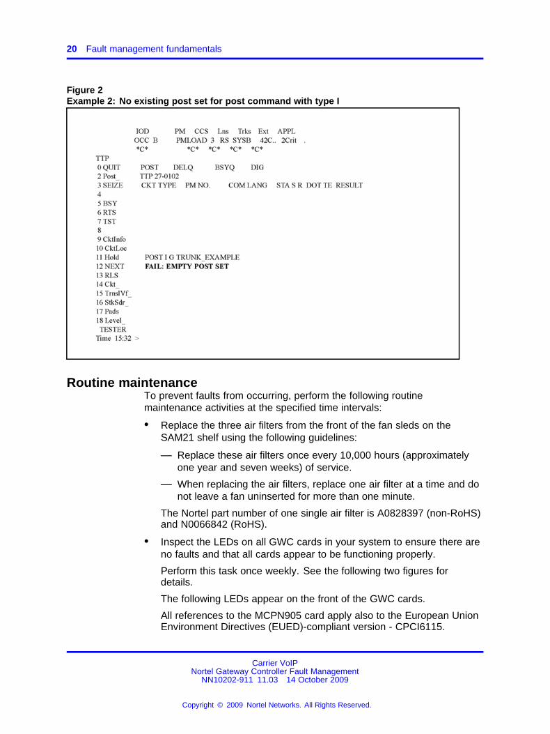
The post command has a post type I with meaning ’Post in existing set’.When a post command with type I is entered, it posts the trunks in theexisting post set (see Figure 1 "Example 1: Post the members of groupTRUNK_EXAMPLE on GWC32" (page 19)). If no post set exists when thepost command with type I is used, the command returns an error message(see Figure 2 "Example 2: No existing post set for post command with typeI" (page 20)).
After the I option, the only valid options are G and D. The D option usedafter the I option supports only the digital equipment GWC and SPM. Onthe GWC, this feature supports trunk types ISUP, PRI, and PTS.
The following figures show examples of the post command using post typeI.
Figure 1Example 1: Post the members of group TRUNK_EXAMPLE on GWC32
Carrier VoIPNortel Gateway Controller Fault Management
NN10202-911 11.03 14 October 2009
Copyright © 2009 Nortel Networks. All Rights Reserved.
.
20 Fault management fundamentals
Figure 2Example 2: No existing post set for post command with type I
Routine maintenanceTo prevent faults from occurring, perform the following routinemaintenance activities at the specified time intervals:
• Replace the three air filters from the front of the fan sleds on theSAM21 shelf using the following guidelines:
— Replace these air filters once every 10,000 hours (approximatelyone year and seven weeks) of service.
— When replacing the air filters, replace one air filter at a time and donot leave a fan uninserted for more than one minute.
The Nortel part number of one single air filter is A0828397 (non-RoHS)and N0066842 (RoHS).
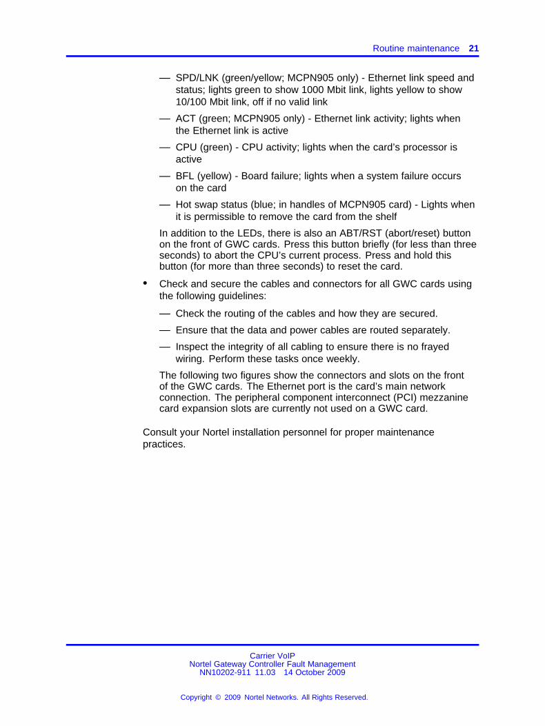
• Inspect the LEDs on all GWC cards in your system to ensure there areno faults and that all cards appear to be functioning properly.
Perform this task once weekly. See the following two figures fordetails.
The following LEDs appear on the front of the GWC cards.
All references to the MCPN905 card apply also to the European UnionEnvironment Directives (EUED)-compliant version - CPCI6115.
Carrier VoIPNortel Gateway Controller Fault Management
NN10202-911 11.03 14 October 2009
Copyright © 2009 Nortel Networks. All Rights Reserved.
.
Routine maintenance 21
— SPD/LNK (green/yellow; MCPN905 only) - Ethernet link speed andstatus; lights green to show 1000 Mbit link, lights yellow to show10/100 Mbit link, off if no valid link
— ACT (green; MCPN905 only) - Ethernet link activity; lights whenthe Ethernet link is active
— CPU (green) - CPU activity; lights when the card’s processor isactive
— BFL (yellow) - Board failure; lights when a system failure occurson the card
— Hot swap status (blue; in handles of MCPN905 card) - Lights whenit is permissible to remove the card from the shelf
In addition to the LEDs, there is also an ABT/RST (abort/reset) buttonon the front of GWC cards. Press this button briefly (for less than threeseconds) to abort the CPU’s current process. Press and hold thisbutton (for more than three seconds) to reset the card.
• Check and secure the cables and connectors for all GWC cards usingthe following guidelines:
— Check the routing of the cables and how they are secured.
— Ensure that the data and power cables are routed separately.
— Inspect the integrity of all cabling to ensure there is no frayedwiring. Perform these tasks once weekly.
The following two figures show the connectors and slots on the frontof the GWC cards. The Ethernet port is the card’s main networkconnection. The peripheral component interconnect (PCI) mezzaninecard expansion slots are currently not used on a GWC card.
Consult your Nortel installation personnel for proper maintenancepractices.
Carrier VoIPNortel Gateway Controller Fault Management
NN10202-911 11.03 14 October 2009
Copyright © 2009 Nortel Networks. All Rights Reserved.
.

22 Fault management fundamentals
Figure 3Details: Motorola N905 NSS board
Carrier VoIPNortel Gateway Controller Fault Management
NN10202-911 11.03 14 October 2009
Copyright © 2009 Nortel Networks. All Rights Reserved.
.

Routine maintenance 23
Figure 4Details: Motorola N750 NSS board
Carrier VoIPNortel Gateway Controller Fault Management
NN10202-911 11.03 14 October 2009
Copyright © 2009 Nortel Networks. All Rights Reserved.
.

24 Fault management fundamentals
Data integrity auditsThis section contains conceptual information related to the following dataintegrity audits:
• “CS 2000 data integrity audit” (page 25)
• “Line data integrity audit” (page 25)
• “Trunk data integrity audit” (page 27)
• “V5.2 data integrity audit” (page 27)
You can perform these audits to check for defective data or if you suspecta provisioning problem. You can also schedule data integrity audits(except CICM line audit). If required, see procedure "Configuring arecurring data integrity audit" in Nortel Gateway Controller Configuration ((NN10205-511)).
Section “Performing a CS 2000 data integrity audit” (page 96)and “ViewingCS 2000 data integrity audit reports” (page 99) contains procedures forperforming and viewing data integrity audits.
Restrictions and limitations
• The audit application keeps no record of problems that caused thealarm. Therefore, if a problem is detected during an audit and it is notcorrected, an alarm is generated for the same problem the next timethe audit runs.
• For each audit type, only one audit can be in progress at any giventime. An in-progress audit blocks all attempts to run any subsequentaudit requests. If you run an on-demand audit, and if that audit is stillin progress at the start time of a scheduled audit, the scheduled auditwill not occur.
This limitation does not apply to a CICM line audit, which can only berun on demand.
• If the Management Tools server is configured in a cluster mode (twonodes: one active and one inactive), you can access and view auditreports only on the node that was active during the audit. If a switch ofactivity (SWACT) occurs after the audit, the new active node does notdisplay any reports. To access audit reports, you need to run the auditagain or perform another SWACT.
Carrier VoIPNortel Gateway Controller Fault Management
NN10202-911 11.03 14 October 2009
Copyright © 2009 Nortel Networks. All Rights Reserved.
.

Data integrity audits 25
CS 2000 data integrity auditThe CS 2000 data integrity audit compares the GWC Manager databasewith the CS 2000 Core or the Session Server Manager database, or bothand flags any mismatches between the databases. The Core is consideredto hold the ’master’ database.
The compares the following data to highlight inconsistencies:
• On the CS 2000 Management Tools server:
— bearer network fabric type of each GWC node
— the network instance of each GWC node
• On the Core:
— the network instance and fabric type contained in the BEARNETStable
— the bearer network type for each GWC node contained in theSERVRINV table
If the audit detects any inconsistencies in this data, the system gives youthe option to attempt to repair them.
If your network configuration includes the Session Server for SIP Linesfunctionality, the audit can also compare the IP-VPN(NAT) network zonesconfiguration data in the GWC Manager and the Session Server Managerdatabases. This data must be consistent to allow the insertion of MediaProxies for SIP lines. For information about the Session Server Linesvirtual gateway, see procedure "Associating a Session Server virtualgateway for SIP Lines" in Nortel Gateway Controller Configuration ((NN10205-511)).
For the Session Server Lines configuration information, see Nortel SessionServer Lines Fundamentals ( (NN10437-111)).
Unlike the line and trunk audits, the CS 2000 data integrity audit does notprovide an option to save the audit report to a file on the local disk.
Line data integrity auditThe line data integrity audit checks the line data stored in the followingdatabases, flags any mismatches, and displays the results of the audit:
• CS 2000 GWC Manager database (SESM)
• Session Server (SS) Manager database (SIP lines)
• Centrex IP Client Manager database (CICM lines)
• CS 2000 Core database
Carrier VoIPNortel Gateway Controller Fault Management
NN10202-911 11.03 14 October 2009
Copyright © 2009 Nortel Networks. All Rights Reserved.
.

26 Fault management fundamentals
For a line audit, the system compares the ENDPOINTENTRY area in theCS 2000 GWC Manager database (SESM) with the following tables in theCS 2000 Core database:
• DNINV
• LGRPINV
• LNINV
• HUNTMEM (if hunt groups are provisioned)
• MDNMEM (if MADN groups are provisioned)
• LTMAP (if ISDN BRI endpoints are provisioned)
SIP lines audit
For SIP lines, the system audits and compares the following data storedin the Session Server (SS) Manager database:
• the endpoints - compares with the GWC Manager database
• group directory number (DN) and member (endpoint/line equipmentnumber [LEN]) information - compares with Core
• DN to LEN mapping - compares with the Core
CICM lines audit
For CICM lines, the system audits and compares data the followingstored in the CICM database. The system combines this data with theset of endpoints held by CS 2000 Management Tools server and sendsit to CICM to perform the audit. The outcome is returned to CS 2000Management Tools server and put into the line audit reports.
• LCC type and M522 extension modules for working lines (tableKSETINV)
• directory number information against EBS set keys (table KSETLINE)
• non-directory number feature key data (table KSETFEAT)
• speed call user feature key data (table SCUFEAT)
The CICM line audit can be run only on demand. The audit supports thefollowing functionality:
• Report only mode - audit against CICM but no data correction
• Correction mode - audit against CICM and refresh CICM data whereappropriate
• the ability to select specific CICM nodes (GW/LGRP granularity) or allnodes
Carrier VoIPNortel Gateway Controller Fault Management
NN10202-911 11.03 14 October 2009
Copyright © 2009 Nortel Networks. All Rights Reserved.
.
Data integrity audits 27
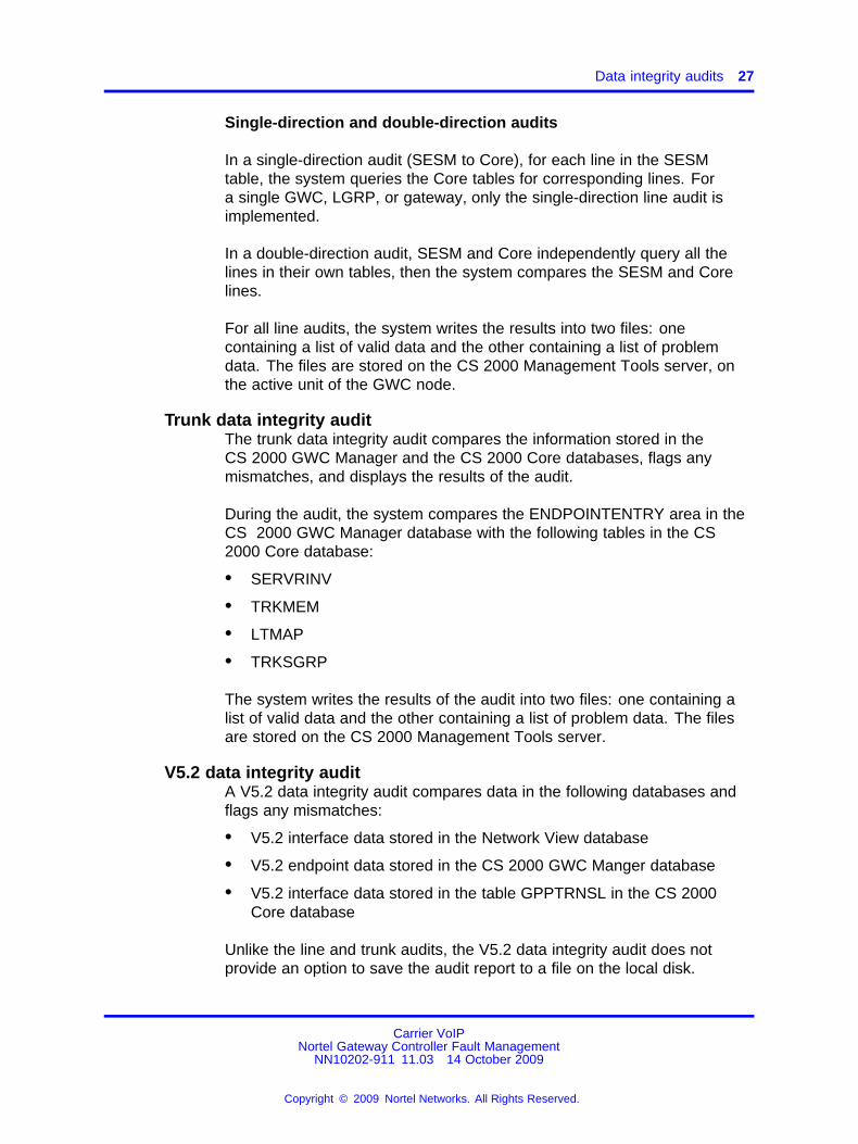
Single-direction and double-direction audits
In a single-direction audit (SESM to Core), for each line in the SESMtable, the system queries the Core tables for corresponding lines. Fora single GWC, LGRP, or gateway, only the single-direction line audit isimplemented.
In a double-direction audit, SESM and Core independently query all thelines in their own tables, then the system compares the SESM and Corelines.
For all line audits, the system writes the results into two files: onecontaining a list of valid data and the other containing a list of problemdata. The files are stored on the CS 2000 Management Tools server, onthe active unit of the GWC node.
Trunk data integrity auditThe trunk data integrity audit compares the information stored in theCS 2000 GWC Manager and the CS 2000 Core databases, flags anymismatches, and displays the results of the audit.
During the audit, the system compares the ENDPOINTENTRY area in theCS 2000 GWC Manager database with the following tables in the CS2000 Core database:
• SERVRINV
• TRKMEM
• LTMAP
• TRKSGRP
The system writes the results of the audit into two files: one containing alist of valid data and the other containing a list of problem data. The filesare stored on the CS 2000 Management Tools server.
V5.2 data integrity auditA V5.2 data integrity audit compares data in the following databases andflags any mismatches:
• V5.2 interface data stored in the Network View database
• V5.2 endpoint data stored in the CS 2000 GWC Manger database
• V5.2 interface data stored in the table GPPTRNSL in the CS 2000Core database
Unlike the line and trunk audits, the V5.2 data integrity audit does notprovide an option to save the audit report to a file on the local disk.
Carrier VoIPNortel Gateway Controller Fault Management
NN10202-911 11.03 14 October 2009
Copyright © 2009 Nortel Networks. All Rights Reserved.
.

28 Fault management fundamentals
Carrier VoIPNortel Gateway Controller Fault Management
NN10202-911 11.03 14 October 2009
Copyright © 2009 Nortel Networks. All Rights Reserved.
.
29.
Fault monitoring and troubleshootingprocedures
This section contains information and procedures associated withmonitoring, analyzing, and troubleshooting GWC fault conditions.
Procedures described in this chapter are optional and do not require thatyou perform them in a specific order.
Carrier VoIPNortel Gateway Controller Fault Management
NN10202-911 11.03 14 October 2009
Copyright © 2009 Nortel Networks. All Rights Reserved.
.

30 Fault monitoring and troubleshooting procedures
Viewing GWC service alarm history
This procedure allows you to query the GWC service-related alarms thatalready occurred, and permits alarm display filtering based on GWC unit,alarm severity, alarm category and date/time.
Use this procedure as a part of scheduled maintenance and as a primarysource of fault diagnostic information for GWC services.
Procedure steps
Step Action
At the CS 2000 GWC Manager client1 From the CS2000 Management Tools window menu, select the
Fault and Alarm History.
2 Review the alarms displayed.
The colors to the left of the alarm display provide a visualindication of alarm severity:
• yellow - warning
• orange - minor
• red - major and critical
3 Click Refresh to update the alarm list.
4 Click the Next Page button (if applicable) to view more alarms.
5 Select the Advanced Filters: Enable check box to open theAdvanced History Filters dialog box and filter alarms based onselected criteria.
If the check box is already selected, click the Settings button toopen the Advanced History Filters dialog box.
Carrier VoIPNortel Gateway Controller Fault Management
NN10202-911 11.03 14 October 2009
Copyright © 2009 Nortel Networks. All Rights Reserved.
.

Procedure steps 31
6 In the View list, select the GWC units to be excluded (filtered).You can press and hold the <Shift> key to select multiple GWCunits.
7 Click the Remove > button to place the selected GWC units inthe Exclude (filtered) list. Click the Remove All >> button toplace all GWC units in the Exclude (filtered) list.
If necessary, select GWC units in the Exclude list. Then, clickthe < Add button to place the selected GWC units in the Viewlist. Click the << Add All button to place all GWC units in theView list.
8 Deselect the Severity check boxes to exclude an alarm type.Any alarm severities that remain selected will not be filtered. Ifrequired, click the Select All button to select all alarm severitycheck boxes.
9 De-select the alarm Category check boxes to exclude an alarmtype. Any alarm categories that remain selected will not befiltered. If required, click the Select All button to select all alarmcategory check boxes.
10 If you wish to filter according to a specific range of dates, typethe date range in the format, yyyy/mm/dd.
11 If you wish to filter according to a specific time frame, type thetime frame in the format, hh:mm.
12 After selecting filter criteria, click the Apply button to displayselected alarms and keep the Advanced History Filters dialogbox open. Click OK to display selected alarms and close theAdvanced History Filters dialog box.
13 To exit the Alarm History, click the File menu at the top of thescreen and select Close.
--End--
Carrier VoIPNortel Gateway Controller Fault Management
NN10202-911 11.03 14 October 2009
Copyright © 2009 Nortel Networks. All Rights Reserved.
.

32 Fault monitoring and troubleshooting procedures
Viewing GWC service alarms
Use this procedure to access service-related alarms that are currentlyactive on the GWC application. The Alarm Manager displays alarms asthey occur (in real time). This option also permits alarm display filteringbased on GWC unit and alarm category.
Use this procedure as a primary source for fault diagnostic informationrelated to GWC services.
Procedure steps
Step Action
1 At the CS 2000 Management Tools window, click the Faultmenu and select Alarm Manager to open the Alarm Managerwindow.
2 From the Alarm Manager window, review the alarms displayed.
The colors to the left of the alarm display provide a visualindication of alarm severity:
• yellow - warning
• orange - minor
• red - major or critical
See section “GWC service alarms” (page 150) for details aboutthe alarm types displayed, including appropriate actions todiagnose and resolve the alarm condition.
3 Click Refresh List to update the alarm list.
4 Click the Details button to review specific details about an alarm.
5 Click the Advanced Filters: Enable check box to open theAdvanced Filters dialog box and filter alarms based on selectedcriteria.
If the check box is already selected, click the Settings button toopen the Advanced Filters dialog box.
Carrier VoIPNortel Gateway Controller Fault Management
NN10202-911 11.03 14 October 2009
Copyright © 2009 Nortel Networks. All Rights Reserved.
.

Procedure steps 33
6 In the view list, select the GWC units to be excluded (filtered).You can press and hold the <Shift> key to select multiple GWCunits.
7 Click the Remove > button to place the selected GWC units inthe Exclude (filtered) list.
Click the Remove All >> button to place all GWC units in theExclude (filtered) list.
If required, select GWC units in the Exclude list. Then, clickthe < Add button to place the selected GWC units in the View(unfiltered) list.
Click the << Add All button to place all GWC units in the View(unfiltered) list.
8 De-select the Alarm Category check boxes to exclude (filter) analarm type for the GWC units listed in the Exclude box.
Any alarm categories that remain selected will be included (willnot be filtered) for the GWC units in the Exclude list.
9 Click the Apply button to display selected alarms and keep theAdvanced Filters dialog box open. Click OK to display selectedalarms and close the Advanced Filters dialog box.
10 To exit the Alarm Manager, click the File menu at the top of thescreen and select Close.
--End--
Carrier VoIPNortel Gateway Controller Fault Management
NN10202-911 11.03 14 October 2009
Copyright © 2009 Nortel Networks. All Rights Reserved.
.

34 Fault monitoring and troubleshooting procedures
Filtering GWC service alarms
Use this procedure to filter (exclude) GWC service-related alarms so youare not distracted by alarms that are not relevant to your current faultmanagement activities. Also, use this procedure to filter recurring alarmsthat you are currently addressing.
Use this procedure when implementing your fault management alarmstrategy or to focus on specific alarms during alarm clearing or diagnosticactivities.
Procedure steps
Step Action
At the CS 2000 GWC Manager client1 From the CS2000 Management Tools window, click the Fault
menu and select Alarm Manager.
The Alarm Manager window opens.
2 At the bottom of the Alarm Manager window, click the AdvancedFilters: Enable check box to open the Advanced Filters dialogbox.
If the check box is already selected, click the Settings button toopen the Advanced Filters dialog box.
Carrier VoIPNortel Gateway Controller Fault Management
NN10202-911 11.03 14 October 2009
Copyright © 2009 Nortel Networks. All Rights Reserved.
.

Procedure steps 35
3 In the View list, select the GWC units to be excluded (filtered).You can press and hold the <Shift> key to select multiple GWCunits.
4 Click the Remove > button to place the selected GWC units inthe Exclude list or click the Remove All >> button to place allGWC units in the Exclude list.
If required, select GWC units in the Exclude list and click the <Add button to place them in the View (unfiltered) list. Click the<< Add All button to place all GWC units in the View list.
5 De-select the Alarm Category check boxes to exclude (filter) analarm type. Any alarm categories that remain selected will beincluded (will not be filtered) - for the GWC units in the Excludelist.
6 After selecting your filter criteria, click the Apply button to displayselected alarms and keep the Advanced Filters dialog box open.Click OK to display selected alarms and close the AdvancedFilters dialog box.
7 To exit the Alarm Manager window, click the File menu in theupper left corner of the screen and select Close.
--End--
Carrier VoIPNortel Gateway Controller Fault Management
NN10202-911 11.03 14 October 2009
Copyright © 2009 Nortel Networks. All Rights Reserved.
.

36 Fault monitoring and troubleshooting procedures
Viewing GWC platform hardware alarms
This procedure provides access to platform-related alarms, such ascommunication over Ethernet, operating system resource availability, andhardware faults.
Use this procedure as a part of alarm clearing activity at the CS 2000SAM21 Manager or as a secondary source of diagnostic information forGWC service-related alarms.
Procedure steps
Step Action
1 Right-click the card in an alarm condition and select Card Viewfrom the menu.
The Card View window opens.
2 Click the Alarms tab to display the alarm details.
Carrier VoIPNortel Gateway Controller Fault Management
NN10202-911 11.03 14 October 2009
Copyright © 2009 Nortel Networks. All Rights Reserved.
.

Procedure steps 37
3 For information about various alarms generated by the SAM21platform, see Nortel SAM21 Shelf Controller Fault Management ((NN10089-911)) .
For information about individual alarms related to the NSS cards(including the GWC card) in the SAM21 Shelf, see
• CS 2000 Management Tools sections in Nortel ATM/IPSolution-level Fault Management ( (NN10408-900))
• in wireless markets - Packet MSC Fault Management(NN-20000-212).
--End--
Carrier VoIPNortel Gateway Controller Fault Management
NN10202-911 11.03 14 October 2009
Copyright © 2009 Nortel Networks. All Rights Reserved.
.
38 Fault monitoring and troubleshooting procedures
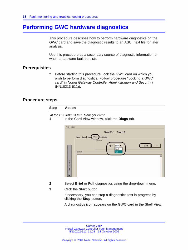
Performing GWC hardware diagnostics
This procedure describes how to perform hardware diagnostics on theGWC card and save the diagnostic results to an ASCII text file for lateranalysis.
Use this procedure as a secondary source of diagnostic information orwhen a hardware fault persists.
Prerequisites• Before starting this procedure, lock the GWC card on which you
wish to perform diagnostics. Follow procedure "Locking a GWCcard" in Nortel Gateway Controller Administration and Security ((NN10213-611)).
Procedure steps
Step Action
At the CS 2000 SAM21 Manager client1 In the Card View window, click the Diags tab.
2 Select Brief or Full diagnostics using the drop-down menu.
3 Click the Start button.
If necessary, you can stop a diagnostics test in progress byclicking the Stop button.
A diagnostics icon appears on the GWC card in the Shelf View.
Carrier VoIPNortel Gateway Controller Fault Management
NN10202-911 11.03 14 October 2009
Copyright © 2009 Nortel Networks. All Rights Reserved.
.

Procedure steps 39
Diagnostic messages appear in the Status area of the CardView.
4 If the test passes, click the Save button at the bottom of theCard View window to save the results on the CS 2000 SAM21Manager client. Choose a name and location for the diagnosticsfile. Append the file with a ".txt" extension for easy identification.To retrieve and print the results, follow procedure “Accessing andprinting GWC diagnostic results” (page 40).
The procedure is complete.
If the hardware diagnostic test fails for any reason, go to the nextstep.
5 Rerun the diagnostics using the Brief test option.
• If the Brief test passes — continue with the next step.
• If the Brief test fails — go to Step 7.
6 Rerun the diagnostics using the Full option.
• If the Full test passes — unlock the card and return it toservice.
ATTENTIONIf you attempt to unlock a card that failed a diagnostic test, thesystem displays a message warning you that the card may notbe fully functional. If this occurs, rerun the diagnostic test. If thecard fails a second time, replace the card and contact your nextlevel of support.
• If the Full test fails — go to the next step.
7 Replace the card. Follow procedure “Replacing andre-provisioning a GWC card” (page 144).
Return the defective card to Nortel according to the proceduresof your service contract.
--End--
Carrier VoIPNortel Gateway Controller Fault Management
NN10202-911 11.03 14 October 2009
Copyright © 2009 Nortel Networks. All Rights Reserved.
.

40 Fault monitoring and troubleshooting procedures
Accessing and printing GWC diagnostic results
Use this procedure to retrieve and print diagnostic results from a savedASCII text file stored on the SAM21 client workstation.
Prerequisites• Perform a diagnostic test using procedure “Performing GWC hardware
diagnostics” (page 38).
Procedure steps
Step Action
At the CS 2000 SAM21 Manager client1 Open a terminal session on the client workstation.
2 Enter:
cat </path/to/file/filename>
3 If a printer is available on the network, print a copy of thediagnostic results. Enter:
lp -c </path/to/log_file/filename> <printername>
--End--
Variable definitionsVariable Value
</path/to/file/filename> The directory location of the diagnostic file
</path/to/log_file/filename> The directory location of the log file
<printername> The system name of the printer connected ormounted to the CS 2000 SAM21 Manager (ifavailable)
Carrier VoIPNortel Gateway Controller Fault Management
NN10202-911 11.03 14 October 2009
Copyright © 2009 Nortel Networks. All Rights Reserved.
.

Procedure steps 41
Viewing and interpreting the operational status of aGWC node
Use this procedure to determine the operational status of a selectedGateway Controller (GWC) node using the CS 2000 GWC Manager. Usethis procedure as a primary source of information about the operationalstatus of a GWC card or GWC node.
Procedure steps
Step Action
1 At the CS 2000 Management Tools window, click the GatewayController folder from the Device Types menu.
2 From the Contents of: Gateway Controller frame, select theGWC node that you wish to view.
3 Click the Maintenance tab.
The GUI displays the Maintenance panel with two independentstatus views, one for each of the GWC cards in the node.
4 See Table 1 "CS 2000 GWC Manager status fields" (page42) following this procedure to interpret the GWC card (unit)status fields.
Carrier VoIPNortel Gateway Controller Fault Management
NN10202-911 11.03 14 October 2009
Copyright © 2009 Nortel Networks. All Rights Reserved.
.

42 Fault monitoring and troubleshooting procedures
If the selected GWC loses communication with the GWCManager, the client does not provide an accurate status of theGWC node. You can verify the call processing status of a GWCnode using the MAPCI interface. If required, follow procedure“Verifying the call processing status of a GWC node” (page 45).
--End--
Job aidThe following table describes the GWC card (unit) status fields.
Table 1CS 2000 GWC Manager status fields
Status field Possible values Meaning
Administrativestate:
locked The unit is prohibited, administratively,from providing service to users.
A status of "locked" on the CS 2000 GWC Manager indicates that the softwareapplication on the card is no longer performing its primary call processingfunction, but the card is still running. (The call processing function has been"busied", but underlying maintenance and communications activities are stillfunctioning.)
A status of "locked" on the CS 2000 SAM21 Manager indicates that thehardware is locked to ROM level, and the software application is no longerrunning.
unlocked The unit is permitted, administratively, toprovide service to users.
Operational state: enabled The unit is partially or fully providingservice to users.
disabled The unit is not operating or providingservice to users. If the Administrative statefor this unit is "locked", then the unit hasbeen manually busied. If the Administrativestate for this unit is "unlocked", then theunit has been busied by the system.
Activity state: active The unit is currently providing end userservices. This is the state of the node asseen by other network elements.
standby The unit is not providing end user servicesbut can be switched to Active at any time ifthe active (mate) unit fails.
Isolation state: isolated The unit is not communicating with theCore.
Carrier VoIPNortel Gateway Controller Fault Management
NN10202-911 11.03 14 October 2009
Copyright © 2009 Nortel Networks. All Rights Reserved.
.

Job aid 43
Table 1CS 2000 GWC Manager status fields (cont’d.)
Status field Possible values Meaning
not isolated The unit is communicating with the Core.
Available state: offLine(3) The unit has not received its configurationdata from the CS 2000 GWC Manager.The unit cannot provide service until it isbooted and receives configuration data.
degraded(6) The unit does not have heartbeatcommunication with its mate and it isoperating without fault-tolerant redundancy.
offLine(3), degraded(6) The unit has both: offline and degradedconditions.
00 00 00 00 The unit does not have either of thepreceding conditions.
Loadname: <string_of_alphanumeric_characters>
This is the name of the load file that theunit currently boots from. The file is locatedon the CS 2000 Core Manager or Coreand Billing Manager (CBM) disk drive.
Usage state: idle The GWC maintenance system is notcurrently working on a request, such asa Return to Service (RTS). The unit isavailable for maintenance requests.
busy Maintenance is in progress on this unit andno further requests are accepted.
Stand by state: providingService The unit is the active unit and is providingservice.
hotStandby The unit is the standby unit - ready toprovide service.
coldStandby The unit is synchronizing with the activeunit (not providing redundancy). Aftercompletion of synchronization, thestatus changes to hotStandby when theOperational state is enabled.
Swact state: This field indicates the last switch ofactivity for the unit.
manualSwActWarm Last switch of activity was due to a manualwarm SwAct. Requested by a user, awarm SwAct causes no service interruptionto stable calls, but calls in the setupprocesses can be lost.
Carrier VoIPNortel Gateway Controller Fault Management
NN10202-911 11.03 14 October 2009
Copyright © 2009 Nortel Networks. All Rights Reserved.
.

44 Fault monitoring and troubleshooting procedures
Table 1CS 2000 GWC Manager status fields (cont’d.)
Status field Possible values Meaning
manualSwActCold Last switch of activity was due to a manualcold SwAct. Requested by a user, a coldSwAct temporarily takes both units out ofservice and takes down all calls.
autonomousSwActWarm Last switch of activity was due to asystem warm SwAct. These SwActs areautomatically performed by the device inresponse to faults or failures. Establishedcalls are preserved. Calls in setup are lost.
autonomousSwActCold Last switch of activity was due to asystem cold SwAct. These SwActs areautomatically performed by the device inresponse to faults or failures. All calls arelost.
noSwAct No switch of activity has occurred.
Alarm state: This field indicates the severity of thecurrently raised alarms.
00 00 00 00 There are no alarms raised on the GWCcard unit.
critical(1) If present, indicates that one or morecritical alarms have been raised.
major(2) If present, indicates that one or more majoralarms have been raised.
minor(3) If present, indicates that one or more minoralarms have been raised.
alarmOutstanding(4) If present, indicates that at least one or acombination of different alarms has beenraised.
Fault state: none(0) This field is not used.
Carrier VoIPNortel Gateway Controller Fault Management
NN10202-911 11.03 14 October 2009
Copyright © 2009 Nortel Networks. All Rights Reserved.
.

Variable definitions 45
Verifying the call processing status of a GWC node
If a GWC loses communication with the GWC Manager, the client does notprovide an accurate status of the GWC node. In this scenario, use thisprocedure to verify the call processing status of a GWC node - using theMAPCI interface.
Procedure steps
Step Action
1 Access the peripheral module maintenance level. Enter:
MAPCI;MTC;PM
2 Post the desired GWC node in the control position. Enter:
post GWC <node_number>
The system displays both GWC units and their current states.
3 Verify the current state of the selected GWC node.
The GWC node can be in one of the following states:
• InSv (in service)If one or both units are in an InSv state, the GWC is capableof performing call processing.
• SysB (system busy) or ManB (manual busy)If both units are in SysB or ManB state, the GWC is notcapable of performing call processing.
--End--
Variable definitionsVariable Value
<node_number> The node number of the GWC that you want topost.
Carrier VoIPNortel Gateway Controller Fault Management
NN10202-911 11.03 14 October 2009
Copyright © 2009 Nortel Networks. All Rights Reserved.
.

46 Fault monitoring and troubleshooting procedures
Viewing switch-wide GWC status
Use this procedure to query switch-wide Gateway Controller (GWC) statusinformation. You can view the status of a specified GWC or all GWCs inyour network. If required, you can also store the information in a file on aspecified device. Use this procedure when needed, for example, whenresponding to a service degradation or an outage.
Commands used in this procedure are not case-sensitive.
Procedure steps
Step Action
At the CI interface1 Access the GWC status level. Enter:
GWCSTAT
System response:
GWCSTAT:
2 This step is optional.
• If you wish to query all subcommands available from theGWCSTAT level, enter:help gwcstat
• If you wish to query the usage of a specific subcommand,enter:help <subcommand>
3 Use the appropriate subcommand to display the requiredinformation associated with a specific GWC or with all GWCs inthe network. For each subcommand,
• [ ] (square brackets) represent optional parameters;
• the default output is console, but you can direct the output toa specified file on a specified device, using the optional "file"parameter.
For detailed description of each command, see Table 2"GWCSTAT commands" (page 50).
Enter one of the following commands:
config <ALL or gwc#> [file <device_name> <file_name>]
OR
status <ALL or gwc#> [file <device_name> <file_name>]
OR
Carrier VoIPNortel Gateway Controller Fault Management
NN10202-911 11.03 14 October 2009
Copyright © 2009 Nortel Networks. All Rights Reserved.
.

Procedure steps 47
alarms <ALL or gwc#> [file <device_name> <file_name>]
OR
gwlist <ALL or gwc#> [file <device_name> <file_name>]
OR
all <ALL or gwc#> [file <device_name> <file_name>]
OR
gwctrkquery gwc <ALL or gwc#> [file <device_name><file_name>]
OR
gwctrkquery clli <clli_name> <member_id_start>[<member_id_end>] [file <device_name> <file_name>]
Example commands and system responses
> config 1
Example system response:
> status all
Example system response:
> gwlist all
Example system response:
Carrier VoIPNortel Gateway Controller Fault Management
NN10202-911 11.03 14 October 2009
Copyright © 2009 Nortel Networks. All Rights Reserved.
.

48 Fault monitoring and troubleshooting procedures
> alarms 0
Example system response:
> all all
This command displays the combined output of thefollowing four commands: config, status, gwlist, andalarms.
> gwctrkquery gwc 1
Example system response:
> gwctrkquery clli 0 1
Example system response:
Carrier VoIPNortel Gateway Controller Fault Management
NN10202-911 11.03 14 October 2009
Copyright © 2009 Nortel Networks. All Rights Reserved.
.

Variable definitions 49
4 If you wish to return to the CI level, enter
QUIT
--End--
Variable definitionsVariable Value
<ALL or gwc#> ALL — use this parameter if you wish to display status informationfor all GWCs in the network.ORA number between 0 and 255 — indicates which specific GWC youwish to query. For example, for GWC-8, enter 8.
[file <device_name><file_name>]
Optional parameter. If you wish to direct the output to a file on aspecified device, enter file, followed by a device name and a filename.
<clli_name> Common language location identifier (CLLI) code of the trunkgroup that you wish to query.
<member_id_start>[member_id_end>]
The trunk member numbers that together define the rangeof trunks within a trunk group that you wish to query. Themember_id_start is a mandatory parameter, but member_id_endis optional.
ExamplesIf you enter 0 for <member_id_start> and 10 for<member_id_end>, the system displays trunks whosemember numbers are between 0 and 10.If you enter the same number for both parameters (forexample, 5 5), the system displays the trunk with membernumber 5).If you enter only the <member_id_start> number, thesystem displays trunks whose member numbers are equalor greater than that specified number. For example, ifyou specify 5, the system displays trunks whose membernumber is equal or greater than 5.
<subcommand> One of the following subcommands available from the GWCSTATlevel: config, status, gwlist, alarms, all, or gwctrkquery.
Carrier VoIPNortel Gateway Controller Fault Management
NN10202-911 11.03 14 October 2009
Copyright © 2009 Nortel Networks. All Rights Reserved.
.

50 Fault monitoring and troubleshooting procedures
Job aidTable 2GWCSTAT commands
Command Description
For all commands listed in this table, if the queried GWC does not respond, the system displaysthe Not Responding message next to the affected GWC.
config Use this command to view the following configuration information for aspecified GWC or for all GWCs in the network:• element manager (EM) IP address
• IP addresses for CORE.
• GWC number
• node number
• active IP address
• profile name
Active IP, Inactive IP, Unit0 IP and Unit1 IP are sequential, increase by 1,so Inactive IP, Unit0 IP and Unit1 IP are not listed in the output. You canderive them from the Active IP.
status Use this command to view the general status information of a specifiedGWC or all GWCs in the network. This command displays the GWC loadname and the following states:• AVAILST (available)
• FAULT
• ADMIN (administrative)
• USAGE
• OPER (operational)
• STANDBY
• ACT (activity)
• SWACTST (Swact)
• ISOLST (isolation)
You can also view this information using the GWC Manager. For moreinformation about these states and their possible values, see Viewing andinterpreting the operational status of a GWC node.
Carrier VoIPNortel Gateway Controller Fault Management
NN10202-911 11.03 14 October 2009
Copyright © 2009 Nortel Networks. All Rights Reserved.
.

Job aid 51
Table 2GWCSTAT commands (cont’d.)
Command Description
gwlist Use this command to display the following information about all gatewaysassociated with a specified GWC or with all GWCs in the network:• gateway name
• gateway IP address
• gateway type (for example, LARGE_GW)
• gateway state (DISABLED or ENABLED)
• protocol name and version (for example, MEGACO 1.0)
• protocol port number
ATTENTIONFor wireline solutions, the following queries are not supported:
• gateways associated with a small line GWCsSystem displays the following message: Small line notsupported
• GWCs with associated RMGC or small line gatewaysSystem displays the following message: Gateway type notsupported
alarms Use this command to list the number of critical, major, minor, and warningalarms for a specified GWC or all GWCs in the network.
all Use this command to display the combined output of the following fourcommands: config, status, gwlist, and alarms.
gwctrkquery gwc Use this command to display the information about trunks associated witha specified GWC or all GWCs in the network. This command lists thefollowing information:• GWC number
• external terminal number (EXTTERMNO)
• trunk group identifier (CLLI)
• trunk member number (MEMBERNO)
• state of the trunk
• subgroup type (SGRPTYPE)
gwctrkquery clli Use this command to display GWC trunks information for a specified trunkgroup. This command lists the following information:• trunk group clli and trunk member number (Trunk:)
• subgroup type (Sgrp Type:)
• state of the trunk
• GWC number
• external terminal number (ExtTermNo:)
Carrier VoIPNortel Gateway Controller Fault Management
NN10202-911 11.03 14 October 2009
Copyright © 2009 Nortel Networks. All Rights Reserved.
.
52 Fault monitoring and troubleshooting procedures
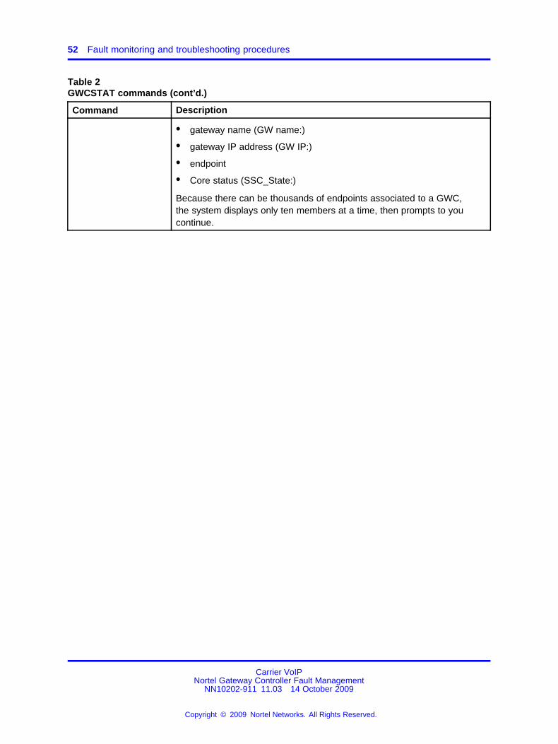
Table 2GWCSTAT commands (cont’d.)
Command Description
• gateway name (GW name:)
• gateway IP address (GW IP:)
• endpoint
• Core status (SSC_State:)
Because there can be thousands of endpoints associated to a GWC,the system displays only ten members at a time, then prompts to youcontinue.
Carrier VoIPNortel Gateway Controller Fault Management
NN10202-911 11.03 14 October 2009
Copyright © 2009 Nortel Networks. All Rights Reserved.
.

Procedure steps 53
Monitoring operational and activity status of GWCs
Use this procedure to access the GWCALL command underMAPCI;MTC;PM level, which allows you to continuously monitoroperational and activity status of all Gateway Controllers (GWC) in thenetwork. The system updates the output whenever the status of any GWCchanges.
Procedure steps
Step Action
At the CI interface1 Access the GWC directory: Enter:
MAPCI;MTC;PM;POST GWC
2 Display the operational and activity status of all GWCs. Enter:
GWCALL
The system displays all GWCs sorted by their number, eachrow represents a unit of GWCs. The system updates the outputwhenever the status of any GWC changes.
For the description of the symbols used in the display, see Table3 "GWCALL status symbols" (page 54).
Example system response:
3 If you wish to return to the CI level, enter
QUIT ALL
--End--
Carrier VoIPNortel Gateway Controller Fault Management
NN10202-911 11.03 14 October 2009
Copyright © 2009 Nortel Networks. All Rights Reserved.
.

54 Fault monitoring and troubleshooting procedures
Job aidTable 3GWCALL status symbols
Symbol Meaning
. (dot) The GWC unit is active and its operational state is InService.
* (star) The GWC unit is inactive and its operational status is InService.
- (dash) The GWC unit is unequipped.
M The GWC unit is active and its operational status is ManB (manuallybusy).
m The GWC unit is inactive and its operational status is ManB.
S The GWC unit is active and its operational status is SysB (system busy).
s The GWC unit is inactive and its operational status is SysB.
O The GWC unit is active and its operational status is Offl (off line).
o The GWC unit is inactive and its operational status is Offl
Carrier VoIPNortel Gateway Controller Fault Management
NN10202-911 11.03 14 October 2009
Copyright © 2009 Nortel Networks. All Rights Reserved.
.

Procedure steps 55
Viewing GWC PM logs
This procedure describes how to access service-related peripheral module(PM) logs generated by the GWC and forwarded to the Core.
Use this procedure as a part of scheduled maintenance and as asecondary source of diagnostic information.
Procedure steps
Step Action
1 Enter:
logutil
2 To retrieve the latest PM log, enter:
open pm
3 For more information about commands available in logutil, enter:
print logutildir
For specific information about the logs, and any actions required,see the PM log descriptions in Nortel Carrier Voice over IP FaultManagement Logs Reference Volume 2 ( (NN10275-909v2)) .
--End--
Carrier VoIPNortel Gateway Controller Fault Management
NN10202-911 11.03 14 October 2009
Copyright © 2009 Nortel Networks. All Rights Reserved.
.

56 Fault monitoring and troubleshooting procedures
Viewing GWC logs in syslog files
This procedure describes how to access GWC logs stored in the syslogfiles on the CS 2000 Management Tools server by logging into the CS2000 Management Tools server. You can also access syslog files usingthe Integrated Element Management System (IEMS) GUI. For moreinformation about viewing the audit and the security logs, see Nortel IEMSAdministration and Security (NN10336-611).
This procedure also describes how to search for specific entries in thesyslog files.
Use this procedure as a part of scheduled maintenance and as asecondary source of diagnostic information.
Prerequisites• You need the root user ID and password to log into the CS 2000
Management Tools server.
Procedure steps
Step Action
1 At your workstation, establish a login session to the CS 2000Management Tools server using one of the following methods:
• telnet (unsecure)For instructions, go to step 2.
• ssh (secure)
ATTENTIONUse this option only if your workstation platform supports ssh.Otherwise, your attempt to log in fails.
For instructions, go to step 7.
2 Enter:
telnet <server>
3 When prompted, enter you user ID and password.
The system prompt changes to a dollar sign ($).
4 Change to the root user. Enter:
su -
5 When prompted, enter the root password.
Carrier VoIPNortel Gateway Controller Fault Management
NN10202-911 11.03 14 October 2009
Copyright © 2009 Nortel Networks. All Rights Reserved.
.

Procedure steps 57
6 Go to step 9 to continue the procedure.
7 Enter:
ssh -1 root <server>
8 When prompted, enter the root password.
The system prompt changes to a dollar sign ($).
9 At the CS 2000 Management Tools client, access the directorylevel where the syslog files reside. Enter:
cd /var/log
10 List the directory content. Enter:
ls
The system displays a list of different log files, such as,customerlog, securitylog, and so on. These files are appendedwith numbers, for example "customerlog.0". The files with thelower numbers are the newer files.
For a list of GWC syslog logs, see “Job aid” (page 58).
11 If the file that you want to view is zipped (has an extension .gz),unzip it using the following command. Otherwise, go to the nextstep.
To unzip the file, enter:
gunzip <log_filename.gz>
Example
$ gunzip securitylog.1.gz
The file changes to a readable file securitylog.1.
12 Enter this command to display the entire content of a log file:
cat <log_filename> |more
Example$ cat customerlog.0 |more
Press the space bar to scroll through the file if it is larger thanthe screen can display.
OR
Enter this command to search and display specific content of alog file:
cat <log_filename> |grep <search_string>
Examples
cat customerlog.0 |grep GWC309
cat securitylog.1 |grep KRB_LOG
Carrier VoIPNortel Gateway Controller Fault Management
NN10202-911 11.03 14 October 2009
Copyright © 2009 Nortel Networks. All Rights Reserved.
.

58 Fault monitoring and troubleshooting procedures
13 If you want to print the file, contact your site system administratorfor assistance with using UNIX print commands and with locatinga printer connected to your network.
--End--
Variable definitionsVariable Value
<log_filename> The name of the log file that you wanto display.
<log_filename.gz> The name of the log file that you wantto unzip.
<search_string> The text that you want to search for.For example, KRB (to search forlogs associated with the Kerberosapplication)
<server> The hostname or IP address of theserver.
Job aidThe following tables describe the syslog logs in the /var/log directory thatcontain entries relevant to the GWC.
Table 4Syslog logs containing GWC entries
Log type DescriptionExamples of log filenames
Audit log Records the actions taken byusers on the system, includingsome of the parameters theyused.
Records all the user logins andlogouts from any source usingftp, proftp, telnet, sftp, scp, orssh. The successful logins andlogouts are logged to auditlog(/var/log/auditlog).
auditlog
auditlog.0
auditlog.1
Customer log Records all alarms the system hasreceived.
customerlog
customerlog.0
customerlog.1
Carrier VoIPNortel Gateway Controller Fault Management
NN10202-911 11.03 14 October 2009
Copyright © 2009 Nortel Networks. All Rights Reserved.
.

Job aid 59
Table 4Syslog logs containing GWC entries (cont’d.)
Log type DescriptionExamples of log filenames
Debug log Records debug information for CS2000 Management Tools networkcomponents to help detect anunderlying problem.
debuglog
debuglog.0
PTM log Contains a record of all the SNMPtraps received by the system.
ptmlog
ptmlog.1
ptmlog.2
Security log Records failed actions taken byusers on the system. Securitylogfile also includes fault-relatedlogs for Kerberos and IKE/IPSecsecurity.
Records all the user logins andlogouts from any source using ftp,proftp, telnet, sftp, scp, or ssh.The login failures are logged tosecuritylog (/var/log/securitylog).
securitylogsecuritylog.0
Use the following table to interpret the syslog application logs on theredirecting media gateway controller (RMGC).
Table 5GWC syslog application logs
Application logdescription Cause or condition Action
RMGC: SuccessfulCount: xFailed Count: y
The RMGC application produces asyslog performance report once anhour. (See the debug log in /var/log.)It contains the counts of the numberof RSIPs processed successfully (x)and the number failed (y). The countsare cumulative, so that to calculate thenumber of successful/failed RSIPs,it is not necessary to parse eachand every log but just to subtract thecounts from the previous log to derivethe counts between the current logand the previous.
No actionrequired
Carrier VoIPNortel Gateway Controller Fault Management
NN10202-911 11.03 14 October 2009
Copyright © 2009 Nortel Networks. All Rights Reserved.
.

60 Fault monitoring and troubleshooting procedures
Accessing the debug log to view GWC auto-imageevents
This procedure describes how to display the content of the CS 2000 GWCManager debug log and search for auto-image events in the log. Thedebug log resides on the CS 2000 Management Tools server.
Use this procedure if you are troubleshooting a problem with auto-imagingand you want to search for a specific auto-image entry in the debug log.
Prerequisites• You must have a user account on the CS 2000 Management Tools
server to access the error log located in the following directory:/opt/nortel/NTsesm/admin/logs.
Procedure steps
Step Action
At the CS 2000 Management Tools client1 Log onto the server as the root user.
2 Change to the /opt/nortel/NTsesm/admin/logs directory. Enter:
cd /opt/nortel/NTsesm/admin/logs
3 Open the debug log. Enter:
less <debug_log_filename>
Example
less ptmdebuglog1.mi2
Example Response
03.01.28 13:30:28.697 VRB (ubsnmp) [PE-8] UBSnmpSimpleTrap Notifying 1 listeners
03.01.28 13:30:28.697 VRB (MI2Server) [PE-8]TrapLogger::trapNotification#queue: 103.01.28 13:30:28.699 VRB (EM) [Thread-78] GWCUtils:Attempting to convert gwcid
4 Search for auto-image events while in the debug log. Enter oneof the following commands:
/auto
/Auto
Carrier VoIPNortel Gateway Controller Fault Management
NN10202-911 11.03 14 October 2009
Copyright © 2009 Nortel Networks. All Rights Reserved.
.

Variable definitions 61
/AUTO
The search string you enter is case sensitive. Each search yieldsdifferent results. The text that you have searched is highlightedin the display.
Example
/Auto
Example response
03.01.29 10:31:34.235 VRB (gwcem@1)[RequestProcessor[1]] SesmSecureProxy::invokeisAutoImagingEnabled03.01.29 10:31:34.236 VRB (gwcem@1)[RequestProcessor[1]]AuthorizingHandler.authorize:isAutoImagingEnabled ()
03.01.29 10:31:34.258 NOA (gwcem@1)[RequestProcessor[1]] AUDIT:isAutoImagingEnabled ()
5 Type n to repeat the previous search in the downwards direction.Type N to repeat the previous search in the reverse direction.
6 Repeat step 4 to search for other entries of the same text in thedebug log, or for different text.
7 Type q to exit.
--End--
Variable definitionsVariable Value
<debug_log_filename> The name of the debug log file. This file namecan be configured. The default file name isptmdebuglog<n>.mi2, where <n> is a numberthat increments as the log increases in size.
Carrier VoIPNortel Gateway Controller Fault Management
NN10202-911 11.03 14 October 2009
Copyright © 2009 Nortel Networks. All Rights Reserved.
.

62 Fault monitoring and troubleshooting procedures
Viewing GWC auto-image error logs
This procedure describes how to display the contents of the auto-imageerror log. This log provides a summary of any errors that preventauto-imaging from taking place. The error log resides on the CS 2000Management Tools server.
The log recycles after recording 2000 lines of text.
Use this procedure when you want to determine if auto-imaging is workingproperly.
Prerequisites• You must have a user account on the CS 2000 Management Tools
server to access the error log located on the CS 2000 ManagementTools server in the following directory: /opt/nortel/NTsesm/admin/logs.
Procedure steps
Step Action
At the CS 2000 Management Tools client1 Log onto the server as the root user.
2 Change to the /opt/nortel/NTsesm/admin/logs directory. Enter:
cd /opt/nortel/NTsesm/admin/logs
3 Display the content of the auto-image error log. Enter:
more AutoImagingErrorLog
Example response
Auto Imaging Executed Tue Jan 28 02:00:01 EST 2003An error occurred while auto imaging: Auto imaginghas not been enabled.
Auto Imaging Executed Wed Jan 29 02:00:01 EST 2003An error occurred while auto imaging: Auto imaginghas not been enabled.
See section “Job aid” (page 63) for some examples ofauto-image logs and suggested actions.
--End--
Carrier VoIPNortel Gateway Controller Fault Management
NN10202-911 11.03 14 October 2009
Copyright © 2009 Nortel Networks. All Rights Reserved.
.

Job aid 63
Job aidThe following table provides examples of auto-image error logs,information on how to interpret them, and suggested actions. Auto-imagelogs are recorded in the format:
Auto Imaging Executed<day><month><dd><hh:mm:ss><yyyy>"log description"
where
day/month/dd/hh:mm:ss/yyyy is the date and timestamp for the log
"log description" is a description of the conditionsor reasons for generating the log.
Table 6Examples of auto-image error logs
Auto-image logdescription Cause or condition Action
An error occurred whileauto imaging: Auto imaginghas not been enabled.
An image of the software loadson your GWC devices wasnot taken automatically atthe scheduled time becauseauto-imaging was not enabled.
Enable auto-imaging usingthe CS 2000 GWC Manager ifyou want to automatically savean up-to-date image of GWCsoftware loads once daily on theCS 2000 Core Manager or Coreand Billing Manager (CBM).
See procedure "Enablingor disabling GWC softwareauto-imaging" in Nortel GatewayController Configuration ((NN10205-511)).
An error occurred whiletrying to connect to theGWC EM.
The CS 2000 ManagementTools server is down.
Restart the CS 2000Management Tools server.
Carrier VoIPNortel Gateway Controller Fault Management
NN10202-911 11.03 14 October 2009
Copyright © 2009 Nortel Networks. All Rights Reserved.
.

64 Fault monitoring and troubleshooting procedures
Interpreting GWC card states
This procedure describes how to determine and interpret the GWC cardstate using the CS 2000 SAM21 Manager.
Use this procedure when you are encountering an unknown card state.
Procedure steps
Step Action
At the CS 2000 SAM21 Manager client1 Review the following figure and determine the card icons that
apply.
These states also apply to Shelf Controllers.
2 To view the card state tab, right-click the card icon and selectCard View .
The Card View window opens.
3 Select the States tab.
Carrier VoIPNortel Gateway Controller Fault Management
NN10202-911 11.03 14 October 2009
Copyright © 2009 Nortel Networks. All Rights Reserved.
.

Job aid 65
4 Use Table 7 "GWC card states and possible actions" (page65) to determine your next action, based on the card’s state.
A status of "locked" on the CS 2000 SAM21 Manager indicatesthat the hardware is locked to ROM level, and the softwareapplication is no longer running.
A status of "locked" on the CS 2000 GWC Manager indicatesthat the software application on the card is still running, but it isno longer performing its primary call processing function.
--End--
Job aidThis section contains job aids related to this procedure.
GWC cards states
Table 7GWC card states and possible actions
State Possible action
locked-disabled-offduty Wait for the firmware flash to complete.Verify that the card changes to thelocked-disabled-none state.
If the GWC card transitions to locked-disabled-degraded, follow the suggestions for that state.
unlocked-disabled-offduty For Call Agent cards, this state also representsthe restart and reload of the call processingapplication during a routine exercise test(RExTst).
When the Shelf Controller performs it’s bootaudit, any GWC card that is not running orbooting is set to this state until the ShelfController recovers the card.
Carrier VoIPNortel Gateway Controller Fault Management
NN10202-911 11.03 14 October 2009
Copyright © 2009 Nortel Networks. All Rights Reserved.
.

66 Fault monitoring and troubleshooting procedures
Table 7GWC card states and possible actions (cont’d.)
State Possible action
locked-disabled-offline (new card) Right-click the card icon and select AssignService from the card context menu. Select thecorrect service from the Assign Service window.
If the question mark icon does not disappear,open the Card View and view the States tab.If the history text area indicates that serviceassignment failed because the service type isincompatible with the hardware, either replacethe card with the correct hardware type, orunassign service from the shelf view and thenassign the correct service type.
locked-disabled-offline(reinsertion)
Wait for Shelf Controller to recognize the cardand reinstate the provisioning information.The question mark icon disappears and thecard transitions to a new state. Refer to thesuggestions for the new state.
If the question mark icon does not disappear,open the Card View window and view the Statestab. If the history text area indicates that serviceassignment failed because the service type isincompatible with the hardware, either replacethe card with the correct hardware type, orunassign service from the shelf view and thenreassign with the correct service type.
If the history text area indicates that the serviceassignment failed because the IP addressis already reserved by another unit, contactnetwork engineering to determine if anotherunit is misconfigured, or if this unit should bereconfigured.
Carrier VoIPNortel Gateway Controller Fault Management
NN10202-911 11.03 14 October 2009
Copyright © 2009 Nortel Networks. All Rights Reserved.
.

Job aid 67
Table 7GWC card states and possible actions (cont’d.)
State Possible action
locked-disabled-none or locked-disabled-degraded
Unlock the card by right-clicking on the cardicon and select Unlock from the card contextmenu.
Rerun diagnostics if the CS 2000 SAM21Manager client generates a "Degraded stateUnlock confirmation window". If diagnostics faila second time, replace the card and contactNortel support personnel.
The active Shelf Controller generates twocritical alarms when the inactive Shelf Controlleris locked. A locked-disabled- degraded state fornon system slot (NSS) cards is also alarmed.
locked-disabled-failed This card is inaccessible. Verify the followingitems:
• Shelf Controllers are in service
• If the Shelf Controllers are in service,replace the card. If the replacement carddoes not enter unlocked-enabled-none,contact Nortel support personnel.
locked-disabled-in test Wait for diagnostics to complete. Verify that thecard changes to the locked-disabled-none state.Optionally monitor diagnostics progress from theCard View window.
unlocked-enabled-degraded This card failed one or more diagnostics andwas Unlocked. See “Unlocking a card that hasfailed a diagnostic test” (page 68) at the end ofthis procedure.
This card may not be providing service or maybe unreliable. Lock and run diagnostics on thiscard. If the card fails diagnostics, replace thiscard and contact Nortel support personnel.
Carrier VoIPNortel Gateway Controller Fault Management
NN10202-911 11.03 14 October 2009
Copyright © 2009 Nortel Networks. All Rights Reserved.
.

68 Fault monitoring and troubleshooting procedures
Table 7GWC card states and possible actions (cont’d.)
State Possible action
locked-disabled-none and alarmed This card has taken more than three minutes tocomplete a lock or unlock request. The alarmclears when the card completes the request oris removed from the shelf.
locked-disabled-failed (no application) The Shelf Controller detects a card in the slot,but cannot determine the MAC address for thecard. Reinsert the card.
Unlocking a card that has failed a diagnostic testThe following message appears on the CS 2000 SAM21 Manager if youattempt to unlock a card that has failed a diagnostic test.
If this occurs, rerun the diagnostic test. If the card fails a second time,replace the card and contact Nortel support personnel.
Information card iconAn additional shelf view card icon indicates that the CS 2000 SAM21Manager client cannot display all the card icons. Click this information iconto view the card state information in a balloon. This icon normally indicatesthat the card type is not supported for the current release of the CS 2000SAM21 Manager software.
Carrier VoIPNortel Gateway Controller Fault Management
NN10202-911 11.03 14 October 2009
Copyright © 2009 Nortel Networks. All Rights Reserved.
.

Job aid 69
Line integrity data audit is design intent. During the audit, avoid doingany maintenance actions, such as GWC status query or GWC swact,and any configuration actions, such as add gwc and delete gwc, becausesometimes the bearer network cannot be retrieved due to responsetimeout from ddms.
Carrier VoIPNortel Gateway Controller Fault Management
NN10202-911 11.03 14 October 2009
Copyright © 2009 Nortel Networks. All Rights Reserved.
.
70 Fault monitoring and troubleshooting procedures
Diagnosing problems with a GWC card that cannotbe booted
Use this procedure to diagnose problems with a GWC card that is installedin the SAM21 shelf but does not appear on the CS 2000 SAM21 Managershelf view and it cannot be booted.
Prerequisites• You must have root user access to the CS 2000 Core Manager or
Core and Billing Manager (CBM) console.
Procedure steps
Step Action
1 Login to the CS 2000 Core Manager or CBM as the root user.
2 Start the CS 2000 Core Manager or CBM maintenance interface.Enter:
sdmmtc
OR
cbmmtc
The system prompt changes to >.
3 Access the applications (APPL) level of the CS 2000 CoreManager or CBM maintenance interface and verify that the BootpLoading Service and File Transfer Service applications are inservice (.). Enter:
appl
Example system response:
Carrier VoIPNortel Gateway Controller Fault Management
NN10202-911 11.03 14 October 2009
Copyright © 2009 Nortel Networks. All Rights Reserved.
.

Procedure steps 71
In SDM, the application "Bootpd and tftpd" is an optionalapplication and may not be installed on your system. In this caseit would not be visible in the APPL level menu. In CBM, "Bootpdand tftpd" does not have a presence on the maintenanceinterface APPL level.
4 If these applications are not in service, busy (Bsy) then returnto services (RTS) the applications. For information aboutbusying applications and returning them to service, see theNortel CS 2000 Core Manager Administration and Security(NN10170-611) or Nortel Core and Billing Manager 800 Securityand Administration (NN10362-611).
If these applications are in service (.), check for bootpd and tftpdmessages in the /var/adm/syslog and /var/adm/daemon.log.
Unless log entries relating to application problems weregenerated, no log file exists for daemon.log.
At the SAM21 frame5 Verify that the GWC card has power by looking for the lighted
yellow or green LEDs on its faceplate.
6 Use a VT100 terminal or a PC with terminal application softwareto connect to the DB9 serial port on the faceplate of the GWCcard.
Use a standard straight through serial cable, rather than a nullmodem cable.
7 Configure the PC software to set the PC serial port to 9600baud, 8 bits, no parity, 1 stop bit.
8 Start the terminal application and select a direct connection fromCOM1.
9 Press and hold the reset button on the faceplate of the GWCcard for 5 seconds.
10 Monitor the boot process on the terminal.
Carrier VoIPNortel Gateway Controller Fault Management
NN10202-911 11.03 14 October 2009
Copyright © 2009 Nortel Networks. All Rights Reserved.
.
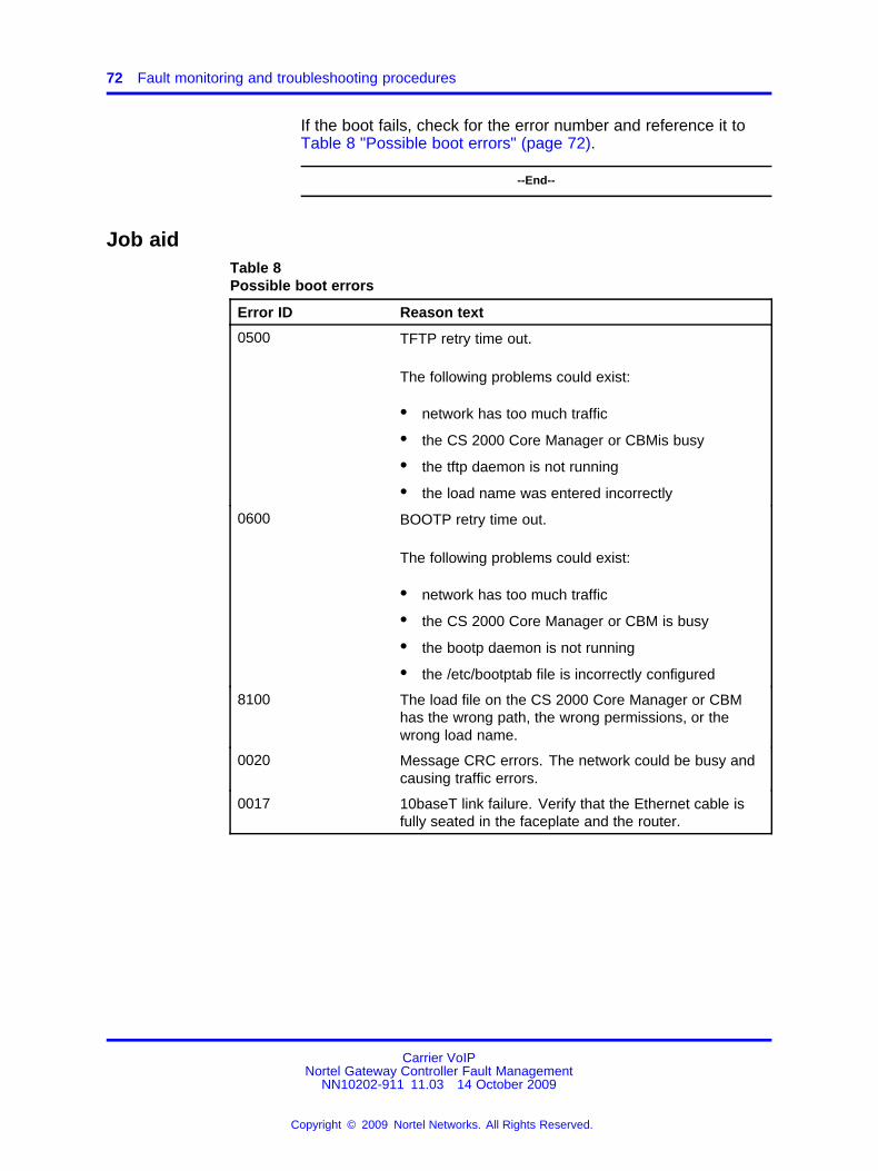
72 Fault monitoring and troubleshooting procedures
If the boot fails, check for the error number and reference it toTable 8 "Possible boot errors" (page 72).
--End--
Job aidTable 8Possible boot errors
Error ID Reason text
0500 TFTP retry time out.
The following problems could exist:
• network has too much traffic
• the CS 2000 Core Manager or CBMis busy
• the tftp daemon is not running
• the load name was entered incorrectly
0600 BOOTP retry time out.
The following problems could exist:
• network has too much traffic
• the CS 2000 Core Manager or CBM is busy
• the bootp daemon is not running
• the /etc/bootptab file is incorrectly configured
8100 The load file on the CS 2000 Core Manager or CBMhas the wrong path, the wrong permissions, or thewrong load name.
0020 Message CRC errors. The network could be busy andcausing traffic errors.
0017 10baseT link failure. Verify that the Ethernet cable isfully seated in the faceplate and the router.
Carrier VoIPNortel Gateway Controller Fault Management
NN10202-911 11.03 14 October 2009
Copyright © 2009 Nortel Networks. All Rights Reserved.
.

Procedure steps 73
Performing a GWC line data integrity audit
This procedure describes how to perform an on-demand data integrityaudit of line data stored in the CS 2000 GWC Manager database (SESM),the Session Server (SS) Manager database (SIP lines), and the CS 2000Core database.
Use this procedure to check for defective data after line provisioning, or ifyou suspect there is a problem with line provisioning.
ATTENTIONDo not run the audit while line provisioning is occurring.
Prerequisites• Review and be familiar with concepts, restrictions and limitations
related to a line data integrity audit. For information, see “Data integrityaudits” (page 24).
• Ensure that there is no other line audit running or scheduled torun. Only one line audit can be in progress at any given time. Anin-progress line audit blocks all attempts to run any subsequent lineaudit requests. If you run an on-demand line audit, and if that audit isstill in progress at the start time of a scheduled audit, the scheduledaudit will not occur. If you wish to view the currently running audits,see procedure “Viewing or aborting running data integrity audits” (page107).
Procedure steps
Step Action
At the CS 2000 GWC Manager client1 At the CS 2000 Management Tools window, select
Maintenance, then Audit System.
The Audit System dialog box appears.
Carrier VoIPNortel Gateway Controller Fault Management
NN10202-911 11.03 14 October 2009
Copyright © 2009 Nortel Networks. All Rights Reserved.
.

74 Fault monitoring and troubleshooting procedures
2 Click the Audit box and from the list of audits, select Line DataIntegrity Audit.
3 Click the Run Audit button.
4 At this time, the system performs the following checks to ensurethat it is ready for the audit:
• Are there 10 or more non-query line provisioning operationsrunning?
• Is the batch provisioning tool (BPT) running a lines batchoperation?
• Is there any bulk query operation in progress?
After each check, if the condition is found, the system displaysan appropriate warning message.
After each warning, you can click the Cancel button to postponethe audit and repeat this procedure at a later time.
If you wish to continue, click the Proceed button on eachdisplayed warning dialog box.
If you click Proceed, the system displays Line Data Integrity auditselection window.
Carrier VoIPNortel Gateway Controller Fault Management
NN10202-911 11.03 14 October 2009
Copyright © 2009 Nortel Networks. All Rights Reserved.
.

Procedure steps 75
The Granular Line Audit list on the left displays all the small andlarge line GWCs and the associated gateways, as well as thelogical line groups (LGRP). You can display or hide any of thesub-lists by clicking on the plus (+) or minus (-) sign.
5 Read the following guidelines, then select the elements that youwish to audit.
• Ensure that the CICM Audit box is not checked.
• If you wish to select more than one item at the same time,press the Shift key and click each item that you want toselect.
• Do not select GWCs and LGRPs for the same audit. If youattempt to select both, the system displays an error message.If you try to select a GWC element and an LGRP is alreadyselected (or the opposite), the system displays the followingwarning:
Click Replace to continue or click Close to start a newselection.
• If you click the Integrity Audit check box (to select all GWCsand associated gateways or all logical groups), the systemdisplays the following confirmation message:
Carrier VoIPNortel Gateway Controller Fault Management
NN10202-911 11.03 14 October 2009
Copyright © 2009 Nortel Networks. All Rights Reserved.
.

76 Fault monitoring and troubleshooting procedures
Click Yes if you wish to continue. Otherwise, click No.
Select the elements that you wish to audit. From the list on theleft,
• click and highlight the specific item that you want to audit(single-direction audit)
OR
• click the Integrity Audit check box to select all GWCsand associated gateways or all logical groups (LGRP)(double-direction audit).If you check the Integrity Audit box, the system displays the"IsDNAudited?" panel.
If you want the system to audit directory-number (DN) data aspart of the line audit, click Yes in the "IsDNAudited?" panel.If you click Yes in the "IsDNAudited" panel, the systemdisplays the following panel.
If you want the system to audit directory-number (DN) data aspart of the line audit, click Yes to continue.If you were to click No in the "IsDNAudited" panel, the systemwould display the following panel.
Carrier VoIPNortel Gateway Controller Fault Management
NN10202-911 11.03 14 October 2009
Copyright © 2009 Nortel Networks. All Rights Reserved.
.
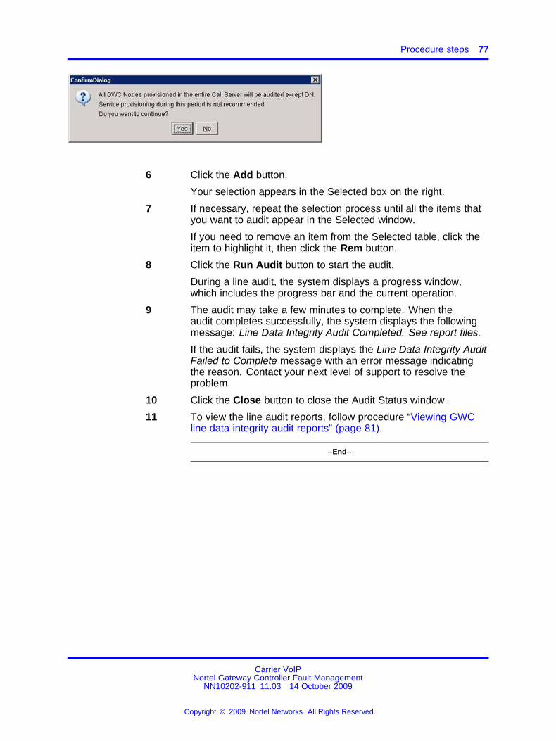
Procedure steps 77
6 Click the Add button.
Your selection appears in the Selected box on the right.
7 If necessary, repeat the selection process until all the items thatyou want to audit appear in the Selected window.
If you need to remove an item from the Selected table, click theitem to highlight it, then click the Rem button.
8 Click the Run Audit button to start the audit.
During a line audit, the system displays a progress window,which includes the progress bar and the current operation.
9 The audit may take a few minutes to complete. When theaudit completes successfully, the system displays the followingmessage: Line Data Integrity Audit Completed. See report files.
If the audit fails, the system displays the Line Data Integrity AuditFailed to Complete message with an error message indicatingthe reason. Contact your next level of support to resolve theproblem.
10 Click the Close button to close the Audit Status window.
11 To view the line audit reports, follow procedure “Viewing GWCline data integrity audit reports” (page 81).
--End--
Carrier VoIPNortel Gateway Controller Fault Management
NN10202-911 11.03 14 October 2009
Copyright © 2009 Nortel Networks. All Rights Reserved.
.

78 Fault monitoring and troubleshooting procedures
Performing a CICM line data integrity audit
This procedure describes how to perform an on-demand data integrityaudit of Centrex IP Client Manager (CICM) lines. Use this procedure tocheck for defective data after line provisioning, or if you suspect there is aproblem with line provisioning.
ATTENTIONDo not run the audit while line provisioning is occurring.
Prerequisites• Make sure that the CICM Manager runs (I)SN09 MR6 or later load and
CBM/SDM and Communication Server 2000 components run (I)SN10or later loads.
• Review and be familiar with concepts, restrictions and limitationsrelated to a line data integrity audit. For information, see “Data integrityaudits” (page 24).
Procedure steps
Step Action
At the CS 2000 GWC Manager client1 At the CS 2000 Management Tools window, select
Maintenance, then Audit System.
The Audit System dialog box appears.
2 Click the Audit box and from the list of audits, select Line DataIntegrity Audit.
Carrier VoIPNortel Gateway Controller Fault Management
NN10202-911 11.03 14 October 2009
Copyright © 2009 Nortel Networks. All Rights Reserved.
.
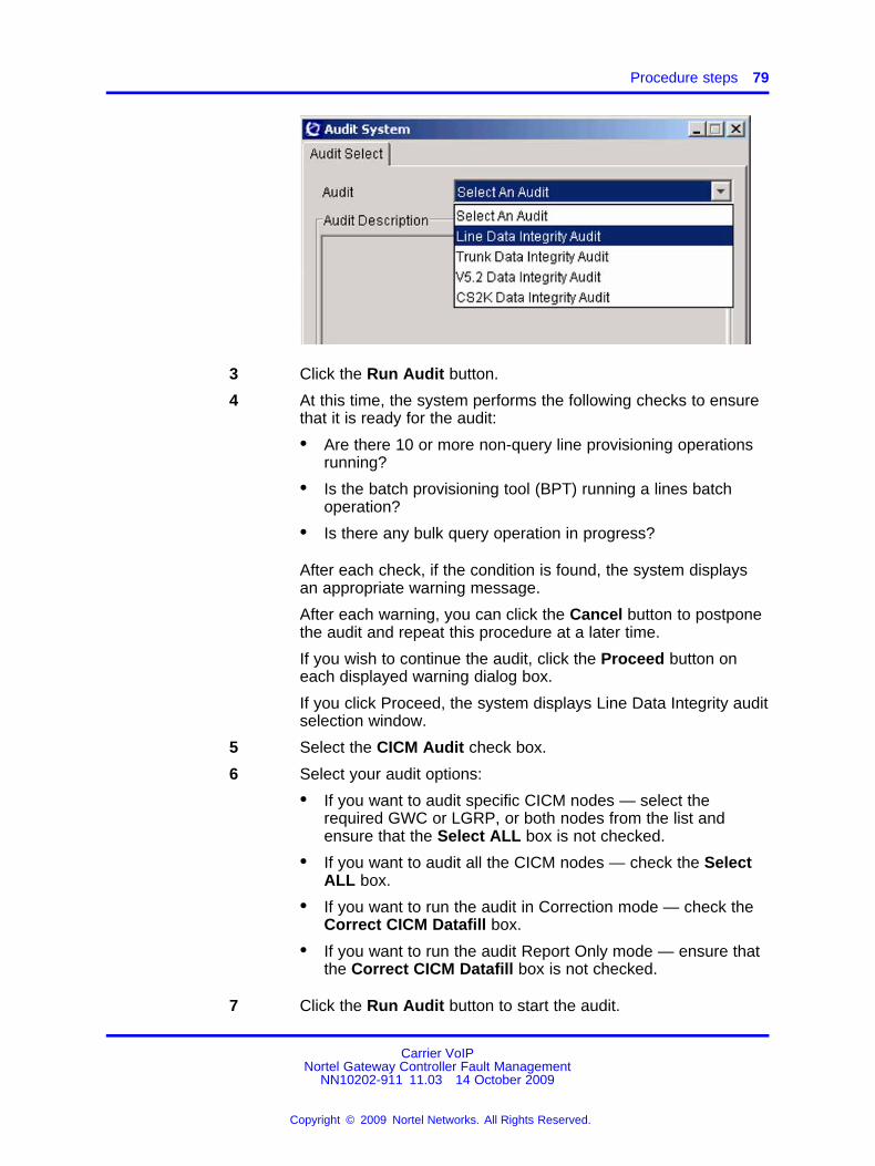
Procedure steps 79
3 Click the Run Audit button.
4 At this time, the system performs the following checks to ensurethat it is ready for the audit:
• Are there 10 or more non-query line provisioning operationsrunning?
• Is the batch provisioning tool (BPT) running a lines batchoperation?
• Is there any bulk query operation in progress?
After each check, if the condition is found, the system displaysan appropriate warning message.
After each warning, you can click the Cancel button to postponethe audit and repeat this procedure at a later time.
If you wish to continue the audit, click the Proceed button oneach displayed warning dialog box.
If you click Proceed, the system displays Line Data Integrity auditselection window.
5 Select the CICM Audit check box.
6 Select your audit options:
• If you want to audit specific CICM nodes — select therequired GWC or LGRP, or both nodes from the list andensure that the Select ALL box is not checked.
• If you want to audit all the CICM nodes — check the SelectALL box.
• If you want to run the audit in Correction mode — check theCorrect CICM Datafill box.
• If you want to run the audit Report Only mode — ensure thatthe Correct CICM Datafill box is not checked.
7 Click the Run Audit button to start the audit.
Carrier VoIPNortel Gateway Controller Fault Management
NN10202-911 11.03 14 October 2009
Copyright © 2009 Nortel Networks. All Rights Reserved.
.

80 Fault monitoring and troubleshooting procedures
The system displays the appropriate confirmation dialog boxlisting the selected audit parameters.
If the displayed audit parameters are not correct, click No and goback to the previous step to select the correct parameters.
Otherwise, click Yes to start the audit.
The system displays a progress window, which includes theprogress bar and the current operation.
8 The audit may take a few minutes to complete. When theaudit completes successfully, the system displays the followingmessage: Line Data Integrity Audit Completed. See report files.
If the audit fails, the system displays the Line Data IntegrityAudit Failed to Complete message, as well as an error messageindicating the reason. Contact your next level of support toresolve the problem.
9 Click the Close button to close the Audit Status window.
10 To view the audit report, follow procedure “Viewing GWC linedata integrity audit reports” (page 81).
--End--
Carrier VoIPNortel Gateway Controller Fault Management
NN10202-911 11.03 14 October 2009
Copyright © 2009 Nortel Networks. All Rights Reserved.
.

Procedure steps 81
Viewing GWC line data integrity audit reports
Use this procedure to view the results of completed line data integrityaudits stored on the CS 2000 Management Tools server, on the active unitof the GWC node.
You can configure the number of reports that the CS 2000 ManagementTools server retains. The maximum default value is seven. When a newline audit occurs, the server deletes the oldest report.
The system places data audit reports in the following directory on theCS 2000 Management Tools server: /opt/nortel/ptm/current/www/Audit/LineDataIntegrityAudit/.
ATTENTIONIf the Management Tools server is configured in a cluster mode (two nodes: oneactive and one inactive), you can access and view audit reports only on thenode that was active during the audit. If a switch of activity (SWACT) occursafter the audit, the new active node does not display any reports. To accessaudit reports, you need to run the audit again or perform another SWACT.
Procedure steps
Step Action
At the CS 2000 GWC Manager client1 At the CS 2000 Management Tools window, select
Maintenance, then Audit System.
The Audit System dialog box appears.
2 Click the Audit box and from the list of audits, select Line DataIntegrity Audit .
Carrier VoIPNortel Gateway Controller Fault Management
NN10202-911 11.03 14 October 2009
Copyright © 2009 Nortel Networks. All Rights Reserved.
.

82 Fault monitoring and troubleshooting procedures
3 Click the Report box and from the drop-down menu, select theValidLineData or the ProblemLineData report that you want toview.
If there is more than one report, verify the and time information inthe report names and decide which report you want to view.
4 Click the View Report button.
The system displays the selected report.
Example valid line data report
Carrier VoIPNortel Gateway Controller Fault Management
NN10202-911 11.03 14 October 2009
Copyright © 2009 Nortel Networks. All Rights Reserved.
.

Procedure steps 83
Example problem line data report
If the audit found no problems, the "Problem" report contains amessage stating that no problems were found.
For Centrex IP Client Manager (CICM)-specific examples, see“Job aid” (page 84).
5 This step applies only to problem reports.
Review the report to see if it contains messages in the followingformats:
• DN <dn> for LEN <len> has no associated endpoint on<GWC ID>To correct this type of problem:
Carrier VoIPNortel Gateway Controller Fault Management
NN10202-911 11.03 14 October 2009
Copyright © 2009 Nortel Networks. All Rights Reserved.
.

84 Fault monitoring and troubleshooting procedures
— Log in directly to the CS 2000 Core (XA-Core or CompactCall Agent).
— Access SERVORD and use the OUT command to removethe DN from the Call Agent.
— Delete the LEN from the Core table LNINV.
• Endpoint <endpoint_name> on gateway <gateway_name> on<GWC_name> has no associated DN/LEN on the CMTo correct this type of problem:
— Log in directly to the CS 2000 Core (XA-Core or CompactCall Agent).
— Manually add the LEN to table LNINV.
6 If you want to retain one of these reports for a longer time, or ifyou want to print a report, click the Save as button at the bottomof the screen to save the report under a new file name.
7 To print the saved report, open the file using text editor and printthe file.
8 For a description of each problem, see the printed copy of theProblemLineData report. To correct the problems, you need todelete and re-provision the listed lines.
9 After viewing the report, click the Exit button at the bottom of thescreen.
--End--
Job aidThis job aid contains examples of CICM line audit outputs.
Valid Line Data logThe valid line data log may contain lines that are also contained in theproblem line data log. This occurs in the following circumstances:
• The feature data is valid but the audit warns that a user is notassigned.
• The audit has found and corrected a problem, so the line is valid postaudit.
The following figure shows an example of a valid line data log as viewedfrom the audit log viewer.
Carrier VoIPNortel Gateway Controller Fault Management
NN10202-911 11.03 14 October 2009
Copyright © 2009 Nortel Networks. All Rights Reserved.
.
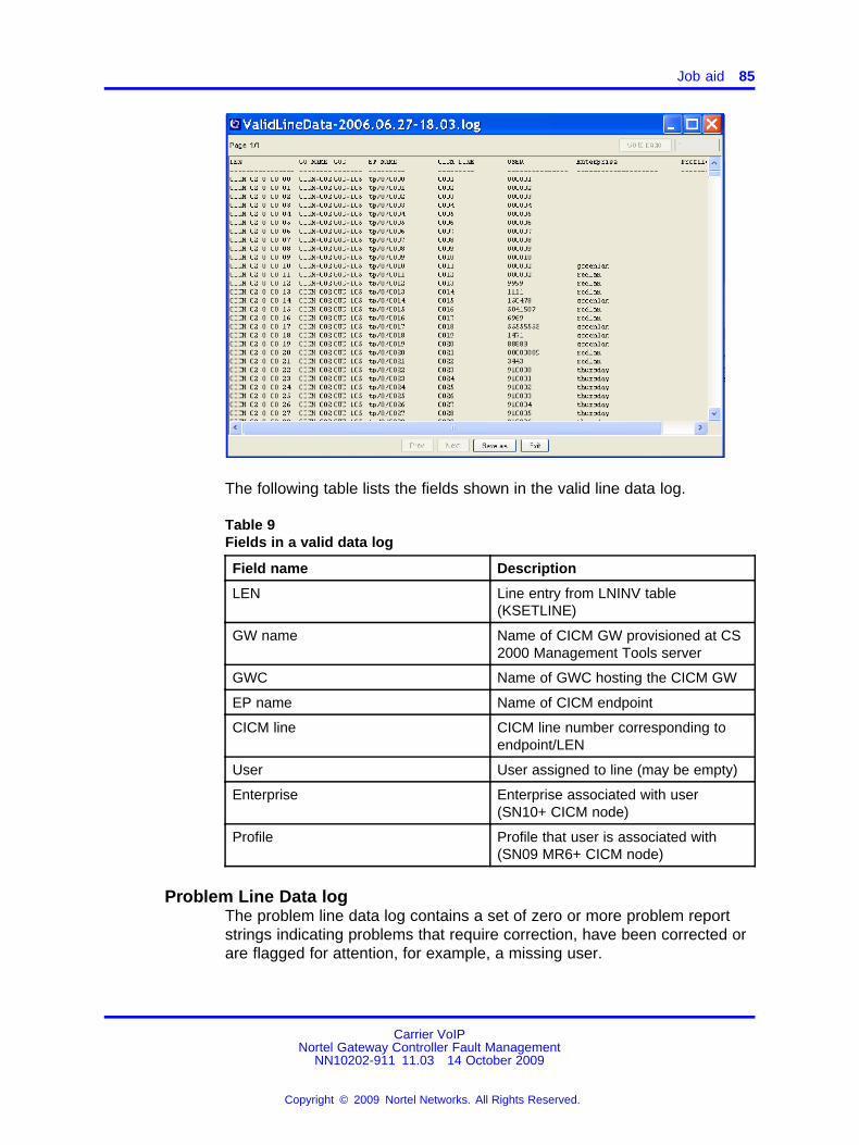
Job aid 85
The following table lists the fields shown in the valid line data log.
Table 9Fields in a valid data log
Field name Description
LEN Line entry from LNINV table(KSETLINE)
GW name Name of CICM GW provisioned at CS2000 Management Tools server
GWC Name of GWC hosting the CICM GW
EP name Name of CICM endpoint
CICM line CICM line number corresponding toendpoint/LEN
User User assigned to line (may be empty)
Enterprise Enterprise associated with user(SN10+ CICM node)
Profile Profile that user is associated with(SN09 MR6+ CICM node)
Problem Line Data logThe problem line data log contains a set of zero or more problem reportstrings indicating problems that require correction, have been corrected orare flagged for attention, for example, a missing user.
Carrier VoIPNortel Gateway Controller Fault Management
NN10202-911 11.03 14 October 2009
Copyright © 2009 Nortel Networks. All Rights Reserved.
.

86 Fault monitoring and troubleshooting procedures
The following figure shows an example of a problem line data log wherethe audit has not been allowed to auto correct the detected problems.
The following figure shows an example of a problem line data log wherethe audit has been allowed to auto correct the detected problems.
Carrier VoIPNortel Gateway Controller Fault Management
NN10202-911 11.03 14 October 2009
Copyright © 2009 Nortel Networks. All Rights Reserved.
.

Job aid 87
The following table shows the problems that may be listed in the problemline data log.
Table 10Possible problems in a line data log
Problem Description Example
HASU_USER Line in HASU state but hasuser entry at CICM.
GWC = GWC-102 GW =CICM-333 EP = tp/0/0456CICM Line = 0456. User ID12345678@greenlan detected onHASU line.
MISSING_USER Line in WORKING state but noprovisioned user.
GWC = GWC-102 GW =CICM-333 EP = tp/1/0001 CICMLine = 1024. No user provisionedon line.
EXT_QUANTITY Mismatch between number ofprovisioned M522 modules.
GWC = GWC-102 GW =CICM-333 EP = tp/2/0121CICM Line = 2167. Provisionedextension module quantitymismatched at CICM.
ILLEGAL_EXT Extension module typeprovisioned at call servernot supported by CICM.
GWC = GWC-102 GW =CICM-333 EP = tp/2/0002CICM Line = 2049. Provisionedextension module unsupported byCICM.
MISMATCH_LCC LCC type provisioned a callserver not supported by CICM.
GWC = GWC-102 GW =CICM-333 EP = tp/2/0002 CICMLine = 2049. Provisioned lineLCC type unsupported by CICM.
FEAT_MISSING Provisioned feature is notpresent on designated key.
GWC = GWC-102 GW =CICM-333 EP = tp/2/0122 CICMLine = 2168. Missing features onCICM key 5.
FEAT_MISMATCH Provisioned feature mismatchbetween CM and CICM.
GWC = GWC-102 GW =CICM-333 EP = tp/2/0122CICM Line = 2168. Mismatchedfeatures on CICM key 12.
UNEXPECTED_FEAT No feature at CM but keyprovisioned at CICM.
GWC = GWC-102 GW =CICM-333 EP = tp/2/0122CICM Line = 2168. Unexpectedfeatures on unassigned CICMkey 3.
Carrier VoIPNortel Gateway Controller Fault Management
NN10202-911 11.03 14 October 2009
Copyright © 2009 Nortel Networks. All Rights Reserved.
.

88 Fault monitoring and troubleshooting procedures
Problem Description Example
INCORRECT_DN DN number at CICM does notmatch the CM.
GWC = GWC-102 GW =CICM-333 EP = tp/2/0122CICM Line = 2168. Incorrect DNon CICM key 1.
INCORRECT_LABEL User string at CICM does notmatch that provisionable byflowthrough provisioning.
GWC = GWC-102 GW =CICM-333 EP = tp/0/0122 CICMLine = 0123. Incorrect User Labelon CICM key 6.
MULTI_ERRORS Large number of mismatchesat CICM; not displayedindividually to prevent floodinglog.
GWC = GWC-102 GW =CICM-333 EP = tp/2/0123 CICMLine = 2169. Multiple mismatchesdetected on line.
HASU_FEAT Feature provisioned against aHASU line
GWC = GWC-102 GW =CICM-333 EP = tp/2/0124 CICMLine = 2170. Features detectedon HASU line.
MISSING_LINE LEN entry at CM butcorresponding CICM lineis missing.
GWC = GWC-102 GW =CICM-333 EP = tp/2/1000 CICMLine = 3046. Line not located inCICM database.
DEL_HASU_USER HASU user at CICM deleted. GWC = GWC-102 GW =CICM-333 EP = tp/0/0456CICM Line = 0456. User ID11111111@redlan deleted fromHASU line.
CORRECT_EXT M522 extension set mismatchcorrected at CICM.
GWC = GWC-102 GW =CICM-333 EP = tp/2/0121 CICMLine = 2167. Corrected extensionmodule quantity mismatch.
ADD_FEAT Missing feature code added tokey on CICM.
GWC = GWC-102 GW =CICM-333 EP = tp/2/0122 CICMLine = 2168. Added missingfeatures to CICM key 5.
CORRECT_FEAT Feature code mismatchcorrected at CICM.
GWC = GWC-102 GW =CICM-333 EP = tp/2/0122CICM Line = 2168. Correctedmismatched features on CICMkey 11.
DEL_FEAT Deleted feature code fromCICM key.
GWC = GWC-102 GW =CICM-333 EP = tp/2/0122 CICMLine = 2168. Deleted unexpectedfeatures on unassigned CICMkey 2.
Carrier VoIPNortel Gateway Controller Fault Management
NN10202-911 11.03 14 October 2009
Copyright © 2009 Nortel Networks. All Rights Reserved.
.

Job aid 89
Problem Description Example
CORRECT_DN Corrected DN number onCICM key.
GWC = GWC-102 GW =CICM-333 EP = tp/2/0122CICM line = 2168. Corrected DNon CICM key 1.
CORRECT_LABEL Corrected label mismatch onCICM key.
GWC = GWC-102 GW =CICM-333 EP = tp/1/0005CICM line = 1028. CorrectedUser Label on CICM key 7.
MULTI_CORRECT Large number of correctionsperformed against CICMline. Not listed individually toprevent flooding log.
GWC = GWC-102 GW =CICM-333 EP = tp/2/0123 CICMLine = 2169. Corrected multiplemismatches on line.
DEL_HASU_LINE All line data fill removed froma HASU line at CICM.
GWC = GWC-102 GW =CICM-333 EP = tp/2/0124 CICMLine = 2170. Deleted featuresfrom HASU line.
UNEXPECTED_REPORT Problem report type notsupport by CICM EM. Not enduser visible.
GWC = GWC-102 GW =CICM-333 EP = tp/2/0124CICM Line = 2170. CICMXMLGWLineParser has detectedan unsupported problem type.
CORRUPT_USER Corruption of user data filldetected at CICM.
GWC = GWC-102 GW =CICM-333 EP = tp/2/0124CICM Line = 2170. "Corrupt userdetected on line. Disassociatefrom line.
CORRECT_CORRUPT_USER
Corruption of user datafill detected at CICM andcorrected by audit.
GWC = GWC-102 GW =CICM-333 EP = tp/2/0124CICM Line = 2170. Corrupt userremoved from line.
AUDIT_LINE_NOT_POSSIBLE
CICM is unable to auditline - indicates Node isout of service or incorrectprovisioning.
GWC = GWC-102 GW =CICM-130 EP = tp/0/0000 CICMLine = ????. Unable to auditCICM Line. Node Missing fromCICM or communication problem.
UNSUPPORT_REPORT This version of the CS 2000Management Tools serverdoes not support the receivedtype of problem report.
Unsupported problem report: 35
Carrier VoIPNortel Gateway Controller Fault Management
NN10202-911 11.03 14 October 2009
Copyright © 2009 Nortel Networks. All Rights Reserved.
.

90 Fault monitoring and troubleshooting procedures
Performing a GWC trunk data integrity audit
This procedure describes how to perform an on-demand data integrityaudit of trunk data stored in the CS 2000 GWC Manager database andthe CS 2000 Core database.
Use this procedure to check for defective data after trunk provisioning, or ifyou suspect there is a problem with trunk provisioning.
ATTENTIONDo not run the audit while trunk provisioning is occurring.
Prerequisites• Review and be familiar with concepts, restrictions and limitations
related to a trunk data integrity audit. For information, see “Dataintegrity audits” (page 24).
• Ensure that there is no other trunk audit running or scheduled torun. Only one trunk audit can be in progress at any given time. Anin-progress trunk audit blocks all attempts to run any subsequent trunkaudit requests. If you run an on-demand trunk audit, and if that auditis still in progress at the start time of a scheduled audit, the scheduledaudit will not occur. If you wish to view the currently running audits,see procedure “Viewing or aborting running data integrity audits” (page107).
Procedure steps
Step Action
At the CS 2000 GWC Manager client1 At the CS 2000 Management Tools window, select
Maintenance, then Audit System.
The Audit System dialog box appears.
Carrier VoIPNortel Gateway Controller Fault Management
NN10202-911 11.03 14 October 2009
Copyright © 2009 Nortel Networks. All Rights Reserved.
.

Procedure steps 91
2 Click the Audit box and from the list of audits, select Trunk DataIntegrity Audit.
3 Click the Run Audit button.
During the audit, the system displays a progress window, whichincludes the progress bar and the current operation.
4 The audit may take a few minutes to complete. When the auditends successfully, the system displays the following message:Trunk Data Integrity Audit Completed. Please see the report file.
If the audit fails, the system displays the Trunk Data IntegrityAudit Failed to Complete message with an error messageindicating the reason. Contact your next level of support toresolve the problem.
5 Click the Close button to close the Audit Status window.
6 To view trunk audit reports, follow procedure “Viewing GWCtrunk data integrity audit reports” (page 92).
--End--
Carrier VoIPNortel Gateway Controller Fault Management
NN10202-911 11.03 14 October 2009
Copyright © 2009 Nortel Networks. All Rights Reserved.
.

92 Fault monitoring and troubleshooting procedures
Viewing GWC trunk data integrity audit reports
Use this procedure to view the results of completed trunk data integrityaudits stored on the CS 2000 Management Tools server.
The CS 2000 Management Tools server retains the six most recentreports. When a new trunk audit occurs, the server deletes the oldestreport.
The system places trunk audit reports in the following directory on theCS 2000 Management Tools server: /opt/nortel/ptm/current/www/Audit/TrunkDataIntegrityAudit/.
ATTENTIONIf the Management Tools server is configured in a cluster mode (two nodes: oneactive and one inactive), you can access and view audit reports only on thenode that was active during the audit. If a switch of activity (SWACT) occursafter the audit, the new active node does not display any reports. To accessaudit reports, you need to run the audit again or perform another SWACT.
Procedure steps
Step Action
At the CS 2000 GWC Manager client1 At the CS 2000 Management Tools window, select
Maintenance, then Audit System.
The Audit System dialog box appears.
2 Click the Audit box and from the list of audits, select Trunk DataIntegrity Audit .
Carrier VoIPNortel Gateway Controller Fault Management
NN10202-911 11.03 14 October 2009
Copyright © 2009 Nortel Networks. All Rights Reserved.
.

Procedure steps 93
3 Click the Report box and from the drop-down menu, select theValidTrunkData or the ProblemTrunkData report that you wantto view.
If there is more than one report, verify the date and timeinformation in the report names and decide which report youwant to view.
4 Click the View Report button.
The system displays the selected report.
Example of a ValidTrunkData report
Carrier VoIPNortel Gateway Controller Fault Management
NN10202-911 11.03 14 October 2009
Copyright © 2009 Nortel Networks. All Rights Reserved.
.

94 Fault monitoring and troubleshooting procedures
Example of a ProblemTrunkData report
If the audit found no problems, the report contains a messagestating that no problems were found.
The ProblemTrunkAudit report can contain messages in thefollowing formats:
• Trunk <trunk name> (node number = <NODE>, terminalnumber = <TID>) has no associated endpoint on GWC<GWC ID>.
• Endpoint <EP NAME> on gateway <GW NAME> (terminalnumber = <TID>) on GWC <GWC ID> has no associatedtrunk member datafilled on the CM.
Carrier VoIPNortel Gateway Controller Fault Management
NN10202-911 11.03 14 October 2009
Copyright © 2009 Nortel Networks. All Rights Reserved.
.

Procedure steps 95
5 If you want to retain one of these reports for a longer time, or ifyou want to print a report, click the Save as button at the bottomof the screen and save the report under a new file name.
6 To print the saved report, open the file using text editor and printthe file.
7 See the printed copy of the ProblemTrunkData report for adescription of each problem. To correct the problems, delete andre-provision the listed trunks.
8 After viewing the report, click the Exit button at the bottom of thescreen.
--End--
Carrier VoIPNortel Gateway Controller Fault Management
NN10202-911 11.03 14 October 2009
Copyright © 2009 Nortel Networks. All Rights Reserved.
.

96 Fault monitoring and troubleshooting procedures
Performing a CS 2000 data integrity audit
This procedure describes how to perform an on-demand data integrityaudit of the CS 2000 Gateway Controller (GWC) Manager, CS2000 Core,and Session Server Manager databases.
Use this procedure when you are receiving logs or alarms on the CS 2000Core or at the CS 2000 SAM21 Manager client indicating a possibleprovisioning errors or data inconsistencies.
When the audit is running, suitable locks are in place that disableprovisioning operations.
Prerequisites• Review and be familiar with concepts, restrictions and limitations
related to a CS 2000 data integrity audit. For information, see “Dataintegrity audits” (page 24).
• Ensure that no provisioning activities are scheduled to take placeduring the audit.
• Ensure that there is no other line audit running or scheduled torun. Only one line audit can be in progress at any given time. Anin-progress line audit blocks all attempts to run any subsequent lineaudit requests. If you run an on-demand line audit, and if that audit isstill in progress at the start time of a scheduled audit, the scheduledaudit will not occur.
Procedure steps
Step Action
1 At the CS 2000 Management Tools window, selectMaintenance, then Audit System.
The Audit System dialog box appears.
Carrier VoIPNortel Gateway Controller Fault Management
NN10202-911 11.03 14 October 2009
Copyright © 2009 Nortel Networks. All Rights Reserved.
.

Procedure steps 97
2 Click the Audit box and from the list of audits, select CS2K DataIntegrity Audit.
3 At the Audit System dialog box, click the Run Audit button todisplay the CS2K Data Integrity Audit Configuration dialog box.
4 Select the CS 2000 component that you wish to audit:
• Select the CS2KSS EM Data Integrity Audit check box —if you wish to verify that the network zones configuration
Carrier VoIPNortel Gateway Controller Fault Management
NN10202-911 11.03 14 October 2009
Copyright © 2009 Nortel Networks. All Rights Reserved.
.

98 Fault monitoring and troubleshooting procedures
data in the GWC Manager and the Session Server Managerdatabases match.
• Select the CS2K Call Server Data Integrity Audit checkbox — if you wish to verify that the data held by the GWCManager database and the CS 2000 Call Server Core match.
• Select both check boxes — if you wish to audit bothcomponents.
If there is no Session Server Manager configured on theCS 2000, the CS2KSS EM Data Integrity Audit check box isdisabled.
5 Click the Run Audit button to start the audit.
If you wish to cancel the process, click the Close button.
During a CS 2000 audit, the system displays a progress windowwith a progress bar.
6 The audit may take a few minutes to complete. When the auditends successfully, the system displays the following message:Audit Completed. Please see report files.
If the audit fails, the system displays the CS2K Data IntegrityAudit Failed to Complete message, with an error messageindicating the reason. Contact your next level of support toresolve the problem.
7 Click the Close button to close the Audit Status window.
8 To view the audit report, follow procedure “Viewing CS 2000data integrity audit reports” (page 99).
--End--
Carrier VoIPNortel Gateway Controller Fault Management
NN10202-911 11.03 14 October 2009
Copyright © 2009 Nortel Networks. All Rights Reserved.
.

Procedure steps 99
Viewing CS 2000 data integrity audit reports
Use this procedure to view the results of completed CS 2000 data integrityaudits.
The system places the audit report in the following directory on the CS2000 Management Tools server: /opt/nortel/ptm/current/MI2/apps/Audit.
The CS 2000 Management Tools server retains the most recent CS 2000audit report. When a new audit occurs, the server deletes the previousreport.
The CS 2000 GWC Manager does not provide an option to save a CS2000 data audit report to the local disk.
ATTENTIONIf the Management Tools server is configured in a cluster mode (two nodes: oneactive and one inactive), you can access and view audit reports only on thenode that was active during the audit. If a switch of activity (SWACT) occursafter the audit, the new active node does not display any reports. To accessaudit reports, you need to run the audit again or perform another SWACT.
Procedure steps
Step Action
1 At the CS 2000 Management Tools window, selectMaintenance, then Audit System.
The Audit System dialog box appears.
2 Click the Audit box and from the list of audits, select CS2K DataIntegrity Audit .
Carrier VoIPNortel Gateway Controller Fault Management
NN10202-911 11.03 14 October 2009
Copyright © 2009 Nortel Networks. All Rights Reserved.
.

100 Fault monitoring and troubleshooting procedures
3 Click the Report box and from the drop-down menu, select thereport that you want to view.
The file name has the following format: Report-<date>
4 Click the View Report button.
The system displays the selected report. If no problems werediscovered, the report is empty.
Example of a CS2K audit report
Carrier VoIPNortel Gateway Controller Fault Management
NN10202-911 11.03 14 October 2009
Copyright © 2009 Nortel Networks. All Rights Reserved.
.

Procedure steps 101
The CS2KSS EM Data Integrity Audit attempts to automaticallycorrect all data mismatches found. The problems listed in thereport are typically corrected and are displayed for informationonly. If any mismatch correction fails, manual action may berequired or the system reattempts the audit, or both.
5 Review the results of the audit and select the problem to resolve.
If necessary, re-size the entire window to view the completeProblem Description field.
6 Click the Actions box and from the drop-down menu, select theappropriate action.
7 Read the description of the action and ensure that you observeany recommended steps or cautions.
8 Click the Take Action button.
If you see the message Correction Failed, contact your next levelof support.
9 Return to Step 5 if you wish to review another problem.
--End--
Carrier VoIPNortel Gateway Controller Fault Management
NN10202-911 11.03 14 October 2009
Copyright © 2009 Nortel Networks. All Rights Reserved.
.

102 Fault monitoring and troubleshooting procedures
Performing a GWC V5.2 data integrity audit
This procedure describes how to perform an on-demand data integrityaudit of V5.2 interfaces.
Use this procedure to check for defective data after you have done V5.2interface provisioning, or if you suspect there is a problem with V5.2provisioning.
When the audit is running, suitable locks are in place that disableprovisioning operations.
Prerequisites• Review and be familiar with concepts, restrictions and limitations
related to a V5.2 data integrity audit. For information, see “Dataintegrity audits” (page 24),
• Ensure that no provisioning activities are scheduled to take placeduring the audit.
• Ensure that there is no other V5.2 audit running or scheduled torun. Only one V5.2 audit can be in progress at any given time. Anin-progress audit blocks all attempts to run any subsequent auditrequests. If you run an on-demand V5.2 audit, and if that audit is stillin progress at the start time of a scheduled audit, the scheduled auditwill not occur. If you wish to view the currently running audits, seeprocedure “Viewing or aborting running data integrity audits” (page107).
Procedure steps
Step Action
At the CS 2000 GWC Manager client1 At the CS 2000 Management Tools window, from the
Maintenance menu, select Audit System.
The Audit System dialog box appears.
Carrier VoIPNortel Gateway Controller Fault Management
NN10202-911 11.03 14 October 2009
Copyright © 2009 Nortel Networks. All Rights Reserved.
.

Procedure steps 103
2 Click the Audit box and from the list of audits, select V5.2 DataIntegrity Audit .
3 Click the Run Audit button to start the audit.
During the audit, the system displays the Audit Status messagebox.
4 The audit may take a few minutes to complete. When the auditcompletes successfully, the system displays one of two types ofmessages :V5.2 Data Integrity Audit Completed. No Problems Found.
V5.2 Data Integrity Audit Completed. 2 Problems Found.
If the audit fails, the system displays the V5.2 Data Integrity AuditFailed to Complete message with an error message indicatingthe reason. Contact your next level of support to resolve theproblem.
5 Click the Close button to close the Audit Status box.
6 To view V5.2 audit reports, complete procedure “Viewing GWCV5.2 data integrity audit reports” (page 104).
--End--
Carrier VoIPNortel Gateway Controller Fault Management
NN10202-911 11.03 14 October 2009
Copyright © 2009 Nortel Networks. All Rights Reserved.
.

104 Fault monitoring and troubleshooting procedures
Viewing GWC V5.2 data integrity audit reports
Use this procedure to view the results of completed V5.2 interface audits.
The CS 2000 Management Tools server retains the most recent report.When a new audit occurs, the server deletes the previous report.
The system places the audit report in the following directory on the CS2000 Management Tools server: /opt/nortel/ptm/current/MI2/apps/Audit.
The CS 2000 GWC Manager does not provide the option to save a V5.2audit report to the local disk.
ATTENTIONIf the Management Tools server is configured in a cluster mode (two nodes: oneactive and one inactive), you can access and view audit reports only on thenode that was active during the audit. If a switch of activity (SWACT) occursafter the audit, the new active node does not display any reports. To accessaudit reports, you need to run the audit again or perform another SWACT.
Procedure steps
Step Action
At the CS 2000 GWC Manager client1 At the CS 2000 Management Tools window, from the
Maintenance menu, select Audit System .
The Audit System dialog box appears.
2 Click the Audit box and from the list of audits, select V5.2 DataIntegrity Audit.
Carrier VoIPNortel Gateway Controller Fault Management
NN10202-911 11.03 14 October 2009
Copyright © 2009 Nortel Networks. All Rights Reserved.
.

Procedure steps 105
3 Click the Report box and from the drop-down menu, select thereport that you want to view.
The file name has the following format: Report-<date>
4 Click the View Report button.
The system displays the selected report. If the audit does notdiscover any problems, the report is empty.
5 Review the results of the audit and select a problem to resolve.
If necessary, re-size the entire window to completely view theProblem Description field.
Carrier VoIPNortel Gateway Controller Fault Management
NN10202-911 11.03 14 October 2009
Copyright © 2009 Nortel Networks. All Rights Reserved.
.

106 Fault monitoring and troubleshooting procedures
6 Click and hold on the Action drop-down menu near the bottomof the screen to assess any possible actions.
7 If appropriate, select an action. Read the description of theaction and ensure that you observe any recommended steps orcautions.
8 Click the Take Action button.
If you see the message Correction Failed, contact your next levelof support.
9 If required, return to Step 5 to review another problem.
--End--
Carrier VoIPNortel Gateway Controller Fault Management
NN10202-911 11.03 14 October 2009
Copyright © 2009 Nortel Networks. All Rights Reserved.
.
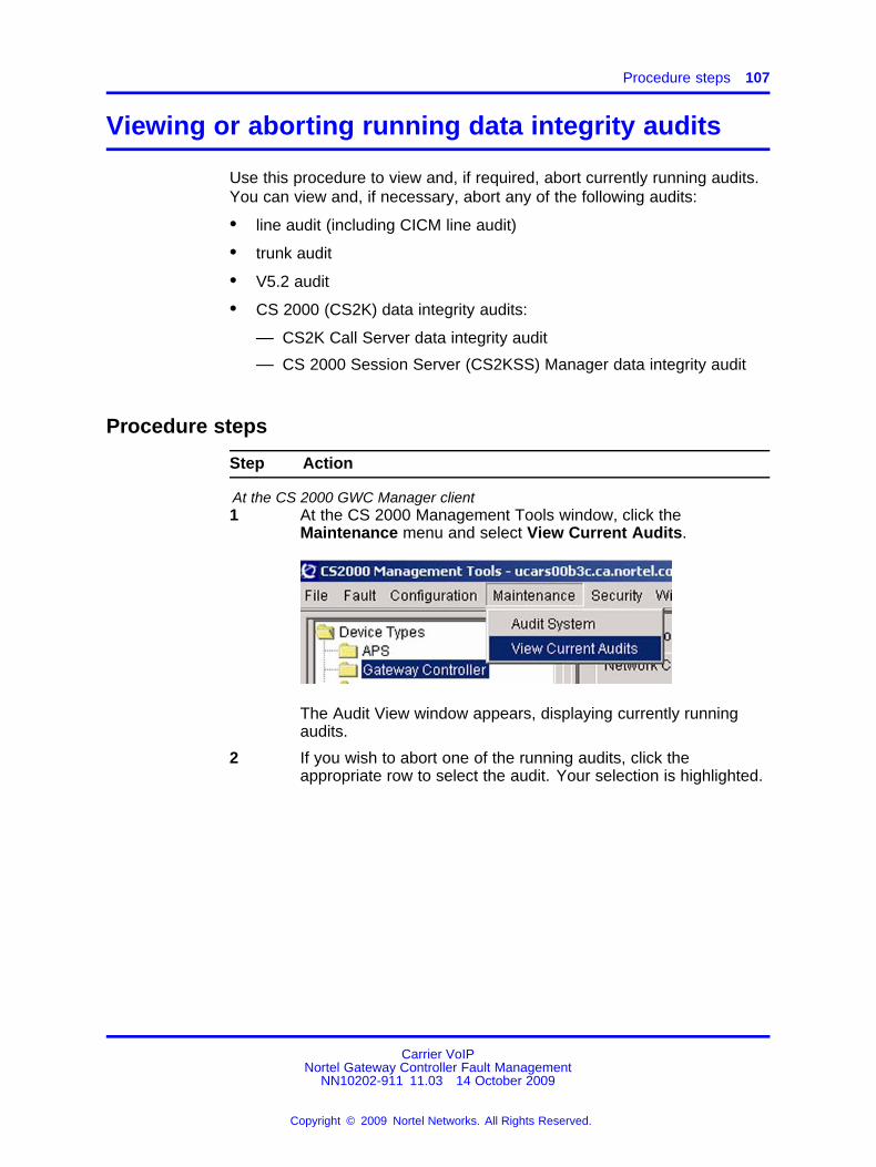
Procedure steps 107
Viewing or aborting running data integrity audits
Use this procedure to view and, if required, abort currently running audits.You can view and, if necessary, abort any of the following audits:
• line audit (including CICM line audit)
• trunk audit
• V5.2 audit
• CS 2000 (CS2K) data integrity audits:
— CS2K Call Server data integrity audit
— CS 2000 Session Server (CS2KSS) Manager data integrity audit
Procedure steps
Step Action
At the CS 2000 GWC Manager client1 At the CS 2000 Management Tools window, click the
Maintenance menu and select View Current Audits.
The Audit View window appears, displaying currently runningaudits.
2 If you wish to abort one of the running audits, click theappropriate row to select the audit. Your selection is highlighted.
Carrier VoIPNortel Gateway Controller Fault Management
NN10202-911 11.03 14 October 2009
Copyright © 2009 Nortel Networks. All Rights Reserved.
.

108 Fault monitoring and troubleshooting procedures
3 Click the Abort button.
At the confirmation window, click OK to continue.
The audit originator receives an error message indicating that theaudit was aborted and identifying the user that aborted the audit.
--End--
Carrier VoIPNortel Gateway Controller Fault Management
NN10202-911 11.03 14 October 2009
Copyright © 2009 Nortel Networks. All Rights Reserved.
.

Procedure steps 109
Setting up protocol trace environment on theCS 2000 Management Tools server
This procedure describes how to set up the trace environment on theCS 2000 Management Tools server, before using the Protocol Trace toolon the Gateway Controller (GWC) to trace protocol packets.
Use this procedure only if you are sent here from procedure “Tracing GWCprotocol packets” (page 112).
Procedure steps
Step Action
At your workstation1 Telnet to the CS 2000 Management Tools server:
telnet <server>
2 When prompted, enter your user ID and password.
The system prompt changes to a dollar sign ($)
3 Change to the root user:
su -root
4 When prompted, enter the root password.
5 Create a directory where the GWCs place the capture (.cap)files. Enter:
mkdir <new_directory_name>
6 Add a new user ID to the mgcmtc user group:
useradd -g mgcmtc -d /<directory_name><new_userid>
You will use this ID to telnet to the GWC and to send (ftp) .capfiles to the CS 2000 Management Tools server.
7 Assign the newly created user ID to the succession user group:
usermod -g succssn -G mgcmtc <userid>
8 Create a password for the user ID you just created:
passwd -r files <userid>
9 When prompted, enter a password of at least three characters.
For more information about how to add new users to usergroups, see procedure "Setting up local user accounts onan SPFS-based server" in Nortel ATM/IP Solution-levelAdministration and Security ( (NN10402-600)).
Carrier VoIPNortel Gateway Controller Fault Management
NN10202-911 11.03 14 October 2009
Copyright © 2009 Nortel Networks. All Rights Reserved.
.

110 Fault monitoring and troubleshooting procedures
10 Associate directory ownership with the created user. Enter:
chown <userid>:mgcmtc /<directory_name>
11 Set up the FTPD user on the CS 2000 Management Toolsserver. Follow procedure "Adding a user to Proftpd" inNortel ATM/IP Solution-level Administration and Security ((NN10402-600)) — using the following configuration values:
• default user path: /<directory_name>
• user_id: <userid>
• group_id: mgcmtc
• maximum clients for this user: 10
• password required for <userid> in group mgcmtc: yEnter the same password you created for the new user inStep 9.
• default path read only: n
• default path write only: n
• user allowed to change directory: n
• user allowed to create/delete directory: n
• user allowed to delete files: y
• user allowed to rename files: y
• user allowed to overwrite files: y
12 Verify the amount of free disk space on the CS 2000Management Tools server. Enter:
df -k
If required, more space can be allocated, but Nortel does notrecommend it.
13 Set a limit file space for the FTPD user configured in stepStep 11. Follow procedure "Setting disk quota for FTP users"in Nortel ATM/IP Solution-level Administration and Security ((NN10402-600)).
Provided that the server has enough disk space available, Nortelrecommends that you set the disk quota to 100 000 Kbytes.
This step ensures that the trace files sent from the GWC do notoverrun the available disk space on the CS 2000 ManagementTools server.
14 Verify that the disk quota is set. Use the following commandoutside of the CLI:
repquota -v /
Carrier VoIPNortel Gateway Controller Fault Management
NN10202-911 11.03 14 October 2009
Copyright © 2009 Nortel Networks. All Rights Reserved.
.

Variable definitions 111
15 Return to procedure “Tracing GWC protocol packets” (page 112).
--End--
Variable definitionsVariable Value
<directory_name> The name of the directory that you created.Example: PkTrace
<new_directory_name> The name of the new directory. Example:PkTrace
<new_userid> The name of the new user. Example: gwcUser
<server> The IP address or host name of the CS 2000Management Tools server.
<userid> The name of the user that you added. Example:gwcUser
Carrier VoIPNortel Gateway Controller Fault Management
NN10202-911 11.03 14 October 2009
Copyright © 2009 Nortel Networks. All Rights Reserved.
.

112 Fault monitoring and troubleshooting procedures
Tracing GWC protocol packets
This procedure describes how to set up and use the Protocol Trace toolon the Gateway Controller (GWC). This tool allows you to set up a sniffertrace on the GWC and direct the output to the CS 2000 ManagementTools server.
Use this procedure as part of troubleshooting and fault clearing activities.
ATTENTIONWithin a GWC telnet session, you can configure and start only one trace foreach GWC unit.
Prerequisites• Before starting this procedure for the first time after an upgrade, you
must set up the trace environment on the CS 2000 Management Toolsserver. Complete procedure “Setting up protocol trace environment onthe CS 2000 Management Tools server” (page 109).
• Review information contained in section “Job aid” (page 118).
Procedure steps
Step Action
At your workstation1 Connect to the GWC node on which you want to start the
protocol trace. Enter:
telnet <GWC_IP>
2 When prompted, login to the GWC. Enter:
<userid>
3 When prompted, enter your password.
The system prompt changes to PROtocoltrace>.
System response:
Warning! The trace captured may contain data thatis restricted by Privacy or CALEA/LI Regulations.The user is responsible to ensure that the captureddata storage, transmission, handling and disposal iswithin procedural, regulatory and legal bounds forjurisdiction(s) where the call is occurring.
Carrier VoIPNortel Gateway Controller Fault Management
NN10202-911 11.03 14 October 2009
Copyright © 2009 Nortel Networks. All Rights Reserved.
.

Procedure steps 113
PROtocoltrace>Duration, END, Help, Ip, Query, Reset, Start, Tcp, Udp,View.
4 If you wish to list all available commands with a shortexplanation, use the Help command. Enter:
h
You can invoke this command at any time.
System response:
You can execute each command (except End) by entering thefull name of the command (for example, reset) or just the firstletter (for example, r).
5 This step is optional. If you wish to obtain port numbers andexternal IP addresses for the gateways, complete one or more ofthe following actions (as applicable):
• For all gateways provisioned through the GWC Manager GUI,use the GUI to obtain the port number and the IP addressfor each gateway. Follow procedure "Viewing gatewayprovisioning data for a GWC node" in Nortel GatewayController Configuration ( (NN10205-511)).
• If the GWC Manager GUI shows an IP address of 0.0.0.0 (agateway is provisioned for a Domain Name Server [DNS]lookup), use the DNS to obtain the gateway IP address.
• For all gateways provisioned through the Core and for anynon-gateway traces (such as, USP M3UA data), trace allpackets for the GWC for 1 minute. Complete procedure“Tracing all packets for a GWC” (page 121), then continuewith this procedure.
Carrier VoIPNortel Gateway Controller Fault Management
NN10202-911 11.03 14 October 2009
Copyright © 2009 Nortel Networks. All Rights Reserved.
.

114 Fault monitoring and troubleshooting procedures
6 Configure trace filters using the following commands: IP and/orUDP, TCP.
You can invoke these commands only when the trace isdisabled. Otherwise, the system displays the following errormessage:
Command rejected: FTP in progress!
For the description of these commands, see section “Tracefilters” (page 119).
ATTENTIONIf you select an IP address with IPSec active, and
• you do not specify any ports (trace filtering based on IPaddress only), the .cap file opened with Wireshark showsEncapsulated Security Payload (ESP) instead of theprotocol name and the payload is not visible.
• you specify the port number (trace filtering based onIP address and port number), the .cap file opened withWireshark shows the protocol name and the payload isvisible.
Packets captured with UDP ports that use IPSec show an invalid IPchecksum (checksum of 0), when .cap file is opened in Wireshark.This is not an error but an indication that the packet was processedto remove the IPSec content. For these packets, ignore the Ethernetaddresses as well.
If you enter:
• IPAt prompts, enter the appropriate IP addresses. If the enteredaddress is not correct, the system displays the following errormessage:Invalid IP address
Example:PROtocoltrace> iEnter external IP 1 (0 = no IP): 47.19.7.9Enter external IP 2 (0 = no IP): 10.1.1.1Enter external IP 3 (0 = no IP): 20.2.2.2Enter external IP 4 (0 = no IP): 30.3.3.3
• UDPAt prompts, enter the appropriate port numbers within therange of 1 to 65535. If you enter an invalid number, thesystem displays the following error message:Invalid port number (range 1 - 65535)
Carrier VoIPNortel Gateway Controller Fault Management
NN10202-911 11.03 14 October 2009
Copyright © 2009 Nortel Networks. All Rights Reserved.
.

Procedure steps 115
Example:PROtocoltrace> uEnter UDP/SCTP Port 1 (0 = N/A): 53Enter UDP/SCTP Port 2 (0 = N/A): 161Enter UDP/SCTP Port 3 (0 = N/A): 162Enter UDP/SCTP Port 4 (0 = N/A): 123
• TCPAt prompts, enter the appropriate port numbers within therange of 1 to 65535. If you enter an invalid number, thesystem displays the following error message:Invalid port number (range 1 - 65535)
Example:PROtocoltrace> tEnter TCP Port 1 (0 = N/A): 23Enter TCP Port 2 (0 = N/A): 21Enter TCP Port 3 (0 = N/A): 1720Enter TCP Port 4 (0 = N/A): 0
7 Configure the duration of the trace using the Duration command.The default value is 30 minutes. If you wish to change it, enter:
d
System response:
Time duration for trace in minutes (1-120):
8 Enter a new value (between 1 and 120 minutes).
If you enter 0 or more than 120, the system displays thefollowing error message:
Invalid Time duration (maximum 2 hours)
You can invoke the Duration command only when the trace toolis disabled. Otherwise, the system displays the following errormessage:
Command rejected: FTP in progress!
9 Verify your configuration using the Query command. Enter:
q
Example response:
TCP ports: 23 21 1720 0Duration set to 15 minutesBuffer wrap mode for buffer size 65536Trace capture stopped
You can invoke the Query command at any time.
Carrier VoIPNortel Gateway Controller Fault Management
NN10202-911 11.03 14 October 2009
Copyright © 2009 Nortel Networks. All Rights Reserved.
.

116 Fault monitoring and troubleshooting procedures
If trace filters are not configured, the response to the Querycommand is:
Configure UDP, TCP and/or IP for trace!
10 If you wish to change the current configuration, use the Resetcommand to set all configuration values to default. Then,configure the new trace filters and new time interval as describedin previous steps.
You can also change any of these configuration valuesseparately at any time by invoking the appropriate command andentering the new value. For example, if you only wish to changethe UDP port, enter the UDP command and enter the new portvalue.
If the displayed current configuration is correct, continue with thenext step.
11
CAUTIONPossible loss of dataIf there any previously captured files from this GWCunit in the FTPD directory on the SESM destination,issuing the Start command will erase those files! Iftheir data needs to be saved prior to starting a newtrace, retrieve them first as described in procedure“Retrieving protocol trace files” (page 123).
Only one trace session may be in progress at any time foreach GWC. Otherwise, the system displays the following errormessage:
Command rejected: FTP in progress!
Start the trace. Enter:
s
System response:
Enter FTP User name (max 32 char):Enter FTP Password (max 32 char):
12 At the prompt, enter the user ID and password that you createdin procedure “Setting up protocol trace environment on theCS 2000 Management Tools server” (page 109).
The password that you enter is displayed on the telnet sessionscreen.
13 If you wish to view the trace in progress, use the View command.Enter:
v
Carrier VoIPNortel Gateway Controller Fault Management
NN10202-911 11.03 14 October 2009
Copyright © 2009 Nortel Networks. All Rights Reserved.
.

Procedure steps 117
You can invoke the View command at any time, but if you enterthis command before the trace starts, the system responds withthe following message:
Trace stopped with reason: not set
Example response, when the trace is in progress:
Trace capture in progress,FTP in progress to host: <CS 2000 Management Toolsserver IP address>Buffered message count = <number of messages in thebuffer> Buffered bytes received = <number of bytes in thebuffer>Total message count = <total number of messages captured>
14 Wait for the trace to complete (based on the configured duration)or terminate the trace using the End command. To avoid anaccidental entry of this command, you must enter the full nameof the command. If you use the End command, all captured datawill be sent to the CS 2000 Management Tools server, then thelast file will close.
To stop the trace, enter:
end
Once all the data is successfully sent to the CS 2000Management Tools server, the system displays the followingmessage:
Continuous Ethereal Trace is done!
If a problem occurs during the trace, the system aborts theprocess and displays the following message:
Continuous Ethereal Trace is aborted!
15 To display the trace details, enter:
v
Example response when the trace ends after the time durationexpires:
Trace stopped with reason: trace doneBuffer message count = <number of messages in the buffer>Buffered bytes received = <number of bytes in the buffer>Total message count = <total number of messages captured>
In this scenario, the total message count matches the number ofpackets in the CAP file.
Example response when you use the End command to stop thetrace:
Carrier VoIPNortel Gateway Controller Fault Management
NN10202-911 11.03 14 October 2009
Copyright © 2009 Nortel Networks. All Rights Reserved.
.
118 Fault monitoring and troubleshooting procedures
Trace stopped with reason: user end cmdBuffer message count = <number> Buffered bytes received =<number>Total message count = <number>
For a list of reasons displayed when the trace is aborted, see jobaid “Reasons for aborting the trace” (page 120).
16 To set all configuration values back to default, use the commandReset. Enter:
r
All ports and IP addresses are set to 0 (no filtering) and the timeduration is set to 30 minutes.
You can invoke this command only when the trace is disabled.Otherwise, the system displays the following error message:
Command rejected: FTP in progress!
17 To retrieve the CAP file from the CS 2000 Management Toolsserver, complete procedure “Retrieving protocol trace files” (page123).
18 On you workstation, open the file with Ethereal or Wireshark andthe appropriate Plug-in.
--End--
Variable definitionsVariable Value
<GWC_IP> The GWC active IP address.
<userid> The user ID that you created when setting up protocoltrace environment on the CS 2000 Management Toolsserver (procedure “Setting up protocol trace environmenton the CS 2000 Management Tools server” (page 109)).
Job aidProtocols and port numbers
The following table lists protocols and most commonly used port numbers.
Table 11Protocols and common port numbers
Protocol In/Out port to capture
BCP (Media Portal) 3904
COPS (DQos) 2126 (TCP)
Carrier VoIPNortel Gateway Controller Fault Management
NN10202-911 11.03 14 October 2009
Copyright © 2009 Nortel Networks. All Rights Reserved.
.

Job aid 119
Table 11Protocols and common port numbers (cont’d.)
Protocol In/Out port to capture
DNS 53
GCP 7060, 7061 - SSL, 5060, 5061 - SST
GWC Connection Broker 22532
GWCCM/FCM 4684
H.248 / MEGACO 2944
H.323 (Q.931)/RAS(H.225) 1719 UDP 1720 TCP
IUAP (Q.931) 9900
MGCP / NCS 2427
M3UA over SCTP 2905
M2UA over SCTP 2904
SNMP 161
TGCP 2427
IKE 500
V5.2 10001
Trace filtersThe following table describes the commands that you use to configuretrace filters.
Table 12Trace filter commands
Command Description
IP The IP command allows you to select up to four IP addresses for filteringagainst source or destination packets. If a TCP or UDP port is configured,the IP check is applied only to packets that passed the port filtering. If youdo not specify any ports, the IP filtering is applied to all IP packets.TCP port 20 is used for FTP data transfer, so packets sent to this port arenot captured, even if the IP address for the packet matches the configuredIP address.
Carrier VoIPNortel Gateway Controller Fault Management
NN10202-911 11.03 14 October 2009
Copyright © 2009 Nortel Networks. All Rights Reserved.
.

120 Fault monitoring and troubleshooting procedures
Command Description
UDP The UDP command allows you to select up to four UDP (user datagramprotocol) or SCTP (stream control transmission protocol) ports for filteringagainst source or destination port. You can also use the IP command toprovide additional filtering on source and destination IP address.
TCP The TCP command allows you to select up to four TCP (transmissioncontrol protocol) ports for filtering against source or destination port. TCPport 20 is used for FTP data transfer, so do not trace this port. If youattempt to trace port 20, the system displays the following error message:TCP port 20 not allowed.
You can also use the IP command to provide additional filtering on sourceand destination IP address.
Reasons for aborting the traceThe following table lists the reasons displayed when the system abortsthe trace.
Table 13Reasons for aborting the trace
Displayed reason Explanation
ftp errorormessage loss
Problem with FTP. If a file is created, it might becorrupted.
ftp throughput Input capture had to stop to avoid buffer overlay ofun-sent data. Trace buffer is too small to buffer captureddata. The trace file contains packets captured until theerror occurred.
ftp forced out Imaging or patching forced the trace FTP to end. Thetrace file contains packets captured until the trace wasforced to end.
Carrier VoIPNortel Gateway Controller Fault Management
NN10202-911 11.03 14 October 2009
Copyright © 2009 Nortel Networks. All Rights Reserved.
.

Action 121
Tracing all packets for a GWC
This procedure describes how to trace all packets for a GWC to obtain portnumbers and external IP addresses of associated gateways.
Use this procedure only if you are sent here from procedure “Tracing GWCprotocol packets” (page 112).
Action
Step Action
At the PROtocoltrace> prompt1 Clear any previous trace settings. Enter:
reset
2 Configure the IP trace filter. Enter:
ip
System response:
Enter external IP 1 (0 = no IP):
3 At the prompt, enter the GWC’s active IP address.
System response:
Enter external IP 2 (0 = no IP):
4 At the prompt, enter 0 (zero).
5 Verify the setting. Enter:
q
Example response:
IP address: xxx.xx.xx.xDuration set to 30 minutesBuffer wrap mode for buffer size 65536Trace capture stopped
6 Start the trace. Enter:
start
System response:
Enter FTP User name (max 32 char):Enter FTP Password (max 32 char):
7 At the prompt, enter the user ID and password that you createdin procedure “Setting up protocol trace environment on theCS 2000 Management Tools server” (page 109).
Carrier VoIPNortel Gateway Controller Fault Management
NN10202-911 11.03 14 October 2009
Copyright © 2009 Nortel Networks. All Rights Reserved.
.

122 Fault monitoring and troubleshooting procedures
The system displays various progress information, including the.cap file name sent to the CS 2000 Management Tools server.
8 After few minutes, stop the trace. Enter:
end
Once the transfer is complete, the system displays the followingmessage:
Continuous Ethereal Trace is done!
9 Retrieve the trace file sent to the CS 2000 Management Toolsserver. Complete procedure “Retrieving protocol trace files”(page 123), then continue with the next step.
10 On you workstation, open the file with Ethereal or Wireshark.
11 From the displayed file, note the port numbers and external IPaddresses for the gateways.
12 Exit the current location. Enter:
logout
13 Return to the procedure that sent you here.
--End--
Carrier VoIPNortel Gateway Controller Fault Management
NN10202-911 11.03 14 October 2009
Copyright © 2009 Nortel Networks. All Rights Reserved.
.

Action 123
Retrieving protocol trace files
Use this procedure to retrieve the Gateway Controller (GWC) protocoltrace files from the CS 2000 Management Tools server.
Action
Step Action
At the ftp> prompt1 Access the CS 2000 Management Tools server. Enter:
<ip_address>
2 When prompted, enter the user ID that you created when settingup the trace environment on the CS 2000 Management Toolsserver (procedure “Setting up protocol trace environment on theCS 2000 Management Tools server” (page 109)).
3 When prompted, enter password.
4 View the list of files. Enter:
ls
The system displays all trace files in the following format:
GWC-x-UNIT-y_n.cap
• x is the GWC node number
• y is the unit number: 0 or 1
• n is the file number, starting with 1
Example response:
Opening ASCII mode data connection for file list-rw-r-r-- 1 gwcpkt mgcmtc 477103 Jul 32 13:15GWC-11-UNIT-1_1.capTransfer complete.
5 Note the name of all trace files (with the extension .cap); forexample, GWC-11-UNIT-1_1.cap.
6 Change to binary mode. Enter:
bin
7 Retrieve all .cap files. Enter:
get <trace_cap_file>
8 Wait until the system displays the Transfer completemessage.
9 Repeat the two previous steps for all .cap trace files that younoted.
Carrier VoIPNortel Gateway Controller Fault Management
NN10202-911 11.03 14 October 2009
Copyright © 2009 Nortel Networks. All Rights Reserved.
.

124 Fault monitoring and troubleshooting procedures
10 To free disk space for the next trace, delete all trace fileswithin FTP from the CS 2000 Management Tools server in thedescending order, starting with the last one created (with thehighest number). For example, if there are three .cap files:_1.cap, _2.cap, _3.cap, delete the _3.cap first, then _2.cap, then_1.cap.
Whenever a new trace starts, the GWC checks if a trace fileexists and tries to delete it. If more than one file exist, the GWConly checks file number _1. If you delete file _1 first and theother files still exist, the GWC does not look for them and startsthe trace.
To delete a .cap trace file, enter:
del <transferred_trace_cap_file>
11 Exit the CS 2000 Management Tools server:
bye
12 Return to the procedure that sent you here.
--End--
Variable definitionsVariable Value
<ip_address> The IP address of the CS 2000 Management Toolsserver.
<trace_cap_file> The name of the trace file (with the extension .cap); forexample, GWC-11-UNIT-1_1.cap.
<transferred_trace_cap_file> The name of the transferred trace file; for example,GWC-11-UNIT-1_1.cap
Carrier VoIPNortel Gateway Controller Fault Management
NN10202-911 11.03 14 October 2009
Copyright © 2009 Nortel Networks. All Rights Reserved.
.

125.
Fault clearing proceduresThis chapter contains GWC fault clearing procedures.
Carrier VoIPNortel Gateway Controller Fault Management
NN10202-911 11.03 14 October 2009
Copyright © 2009 Nortel Networks. All Rights Reserved.
.

126 Fault clearing procedures
Clearing the GWC318 critical alarm manually
This procedure describes how to manually clear the GWC318 criticalalarm.
GWC318 critical alarm is raised when a GWC initiates an autonomousswitch of activity (SWACT) in an attempt to restore communication with itsassociated media gateways.
Use this procedure after the autonomous SWACT occurred and theproblem on the original active unit is solved and you wish to clearGWC318 critical alarm manually.
Prerequisites• The autonomous SWACT occurred and the GWC318 critical alarm is
raised.
• The problem on the original active unit is solved.
Procedure steps
Step Action
At the CS 2000 GWC Manager client1 At the CS 2000 Management Tools window, click the Gateway
Controller folder from the Device Types menu.
2 From the Contents of: Gateway Controller frame, select theGWC node on which the alarm is raised.
3 Click the Provisioning tab and the Controller tab.
Carrier VoIPNortel Gateway Controller Fault Management
NN10202-911 11.03 14 October 2009
Copyright © 2009 Nortel Networks. All Rights Reserved.
.

Procedure steps 127
4 Click the GWC Autonomous Swact: Change button. TheChange GWC Autonomous Swact dialog box opens.
5 Click the Clear Alarm button.
6 At the confirmation window, click OK to confirm your request.
If you wish to cancel the operation, click No and then Cancel .
--End--
Carrier VoIPNortel Gateway Controller Fault Management
NN10202-911 11.03 14 October 2009
Copyright © 2009 Nortel Networks. All Rights Reserved.
.

128 Fault clearing procedures
Clearing the GWC320 Phase 1 SA failure alarm
Use this procedure to clear a GWC320 critical alarm raised for the following specific problem: Phase 1 SA failure - <remote_gateway_IP_address>.
Prerequisites• Verify whether any security logs associated with the alarm exist in the
syslog file. Follow procedure “Viewing GWC logs in syslog files” (page56), searching for the text string ISAKMP_FAIL. An ISAKMP_FAIL logwith the same date and time as the alarm may indicate the precisereason for the failure.
For the description of all IKE/IPSec security logs, see section “IPSecand IKE security logs” (page 170)
• Make sure that the remote media gateway is enabled and that theIPSec on the remote gateway is enabled.
Procedure steps
Step Action
At your workstation1 Launch the CS 2000 Management Tools client application. If
required, see procedure "Launching CS 2000 Management Toolsand NPM client applications" in Nortel ATM/IP Solution-levelAdministration and Security ( (NN10402-600)).
At the CS 2000 GWC Manager client2 At the CS 2000 Management Tools window, click the Gateway
Controller folder from the Device Types menu.
3 From the Contents of: Gateway Controller frame, select theGWC node on which the alarm is raised.
4 Click the Provisioning tab, the IPSec tab, then the ConnectionPolicy tab to display connection policies currently configured forthe selected GWC node.
5 In the Remote host address column, find the IP address thatmatches the <remote_gateway_IP_address> in the alarm.
Carrier VoIPNortel Gateway Controller Fault Management
NN10202-911 11.03 14 October 2009
Copyright © 2009 Nortel Networks. All Rights Reserved.
.

Procedure steps 129
If there is more than one policy with the same Remote hostaddress, select the one with the lowest policy ID. Click that rowto highlight the policy.
The policy with the lowest ID number has the highest priority andthe GWC will select that policy.
6 If the highlighted policy is
• BYPASS or DISCARD — stop the procedure and contactyour next level of support!
• FLEX or SECURE — continue the procedure.
7 For the highlighted policy, verify that the IKE Authentication IPaddress matches the Remote host address.
If these two addresses do not match, stop the procedure andreconfigure the connection policy correctly. For full instructions,see Nortel CVoIP IPSec Service Configuration ( (NN10453-100)).
If these two addresses match, continue the procedure.
8 Click the IKE Authentication tab.
9 In the IKE remote gateway column, find the IP address thatmatches the <remote_gateway_IP_address> in the alarm. Fromthe selected IKE authentication row, note the name of the IKEpreference list.
10 Click the IKE Preference List tab. Find the preference list namethat matches the name noted in Step 9.
11 Note the names of all preferences included in the list (displayedin the Preference list column). Each preference list can includeup to three preferences.
12 Click the IKE Preference tab.
Carrier VoIPNortel Gateway Controller Fault Management
NN10202-911 11.03 14 October 2009
Copyright © 2009 Nortel Networks. All Rights Reserved.
.

130 Fault clearing procedures
Under IKE preference name heading, find the preferences notedin the previous step and verify that the configuration values for atleast one preference match the values configured on the remotegateway.
If the remote gateway is a Media Gateway 9000, verify that oneof the preferences has the following values:
• Cipher algorithm = 3DES-CBC
• Hash algorithm = SHA
• Lifetime = 86400
• Diffie-Hellman key group = 1
13 If the IKE preference values match, stop the procedure andcontact your next level of support.
If the IKE preference values do not match, go to the next step.
14 Add a new IKE preference and IKE preference list with theconfiguration values that match the values configured on theremote gateway.
If required, see procedure "Configuring IKE Preference andPreference List" in Nortel CVoIP IPSec Service Configuration ((NN10453-100)).
15 Modify the IKE authentication selected in Step 9 by selecting thenew IKE preference list.
If required, see procedure "Modifying IKE authentication_changeIKE preference list" in Nortel CVoIP IPSec Service Configuration( (NN10453-100)).
16 If the alarm clears within 5 minutes, the procedure is complete.
If the alarm does not clear within 5 minutes, contact your nextlevel of support.
--End--
Carrier VoIPNortel Gateway Controller Fault Management
NN10202-911 11.03 14 October 2009
Copyright © 2009 Nortel Networks. All Rights Reserved.
.

Procedure steps 131
Clearing the GWC320 Phase 2 SA failure alarm
Use this procedure to clear a GWC320 critical alarm raised for the following specific problem: Phase 2 SA failure - <remote_gateway_IP_address>.
Prerequisites• Verify whether any security logs associated with the alarm exist in the
syslog file. Follow procedure “Viewing GWC logs in syslog files” (page56), searching for the text string ISAKMP_FAIL. An ISAKMP_FAIL logwith the same date and time as the alarm may indicate the precisereason for the failure.
For the description of all IKE/IPSec security logs, see procedure “IPSecand IKE security logs” (page 170).
• Make sure that the remote media gateway is enabled and that theIPSec on the remote gateway is enabled.
Procedure steps
Step Action
At your workstation1 Launch the CS 2000 Management Tools client application. If
required, see procedure "Launching CS 2000 Management Toolsand NPM client applications" in Nortel ATM/IP Solution-levelAdministration and Security ( (NN10402-600)).
At the CS 2000 GWC Manager client2 At the CS 2000 Management Tools window, click the Gateway
Controller folder from the Device Types menu.
3 From the Contents of: Gateway Controller frame, select theGWC node on which the alarm is raised.
4 Click the Provisioning, IPSec , then Connection Policy tabs todisplay connection policies currently configured on the selectedGWC node.
5 In the Remote host address column, find the IP address thatmatches the <remote_gateway_IP_address> in the alarm.
Carrier VoIPNortel Gateway Controller Fault Management
NN10202-911 11.03 14 October 2009
Copyright © 2009 Nortel Networks. All Rights Reserved.
.

132 Fault clearing procedures
If there is more than one policy with the same Remote hostaddress, select the one with the lowest policy ID. Click that rowto highlight the policy.
The policy with the lowest ID number has the highest priority andthe GWC will select that policy.
The remote host IP address must match the IKE Authenticationgateway IP address displayed in the same row.
6 If the highlighted policy is
• BYPASS or DISCARD — stop the procedure and contactyour next level of support.
• FLEX or SECURE — continue the procedure.
7 Note the name of the IPSec preference list configured for theselected connection policy.
8 Click the IPSec Preference List tab. Find the preference listname that matches the name noted in the previous step.
9 Note the names of all preferences included in the list (displayedin the Preference list column). Each preference list can includeup to five preferences.
10 Click the IPSec Preference tab.
11 Under IPSec preference name heading, find the preferencesnoted in Step 9 and verify that the configuration values for atleast one preference match the values configured on the remotegateway.
If the remote gateway is a Media Gateway 9000, verify that oneof the preferences has the following values:
• ESP cipher algorithm = ESP_NULL
• ESP HMAC algorithm = SHA
Carrier VoIPNortel Gateway Controller Fault Management
NN10202-911 11.03 14 October 2009
Copyright © 2009 Nortel Networks. All Rights Reserved.
.

Procedure steps 133
• Lifetime = 57600
• PFS: Diffie-Hellman key group = 1
12 If IPSec preference values
• match — stop the procedure and contact your next level ofsupport.
• do not match — go to the next step.
13 Add a new IPSec preference and IPSec preference list with theconfiguration values that match the values configured on theremote gateway.
If required, see procedure "Configuring IPSec Preference andPreference List" in Nortel Gateway Controller Administration andSecurity ( (NN10213-611)).
14 Change the connection policy selected in step 5 by selecting thenew IPSec preference list.
If required, see the appropriate steps in procedure "Modifying anexisting IPSec connection policy" in Nortel Gateway ControllerAdministration and Security ( (NN10213-611)).
15 If the alarm does not clear within 5 minutes, contact your nextlevel of support. Otherwise, the procedure is complete.
--End--
Carrier VoIPNortel Gateway Controller Fault Management
NN10202-911 11.03 14 October 2009
Copyright © 2009 Nortel Networks. All Rights Reserved.
.

134 Fault clearing procedures
Changing the MAC address of a GWC card
This procedure describes how to automatically re-provision a known goodGWC card with a new media access control (MAC) address. All other cardinformation including IP addresses, port addresses, gateway addresses,and load paths remain unchanged.
Use this procedure when you need to change the MAC address of a GWCcard due to possible address conflicts or to ensure information in theCS 2000 SAM21 Manager database is correct.
Procedure steps
Step Action
At the CS 2000 GWC Manager client1 At the CS 2000 Management Tools window, click the Gateway
Controller folder from the Device Types directory tree in the farleft frame.
2 From the Contents of: Gateway Controller frame, select theGWC node for which you want to change the MAC address, ortype the name of the GWC node in the text field to the left of theGo To button.
3 If the GWC card you need to automatically re-provision iscurrently providing service, switch call processing between thetwo GWC units.
Follow procedure "Invoking a manual protection switch (warmSWACT)" in Nortel Gateway Controller Administration andSecurity ( (NN10213-611)).
4 Busy the card that you want to re-provision (typically, thestandby card in the node). Click the Maintenance tab, then clickthe Busy (Disable) button.
When prompted, click OK.
Carrier VoIPNortel Gateway Controller Fault Management
NN10202-911 11.03 14 October 2009
Copyright © 2009 Nortel Networks. All Rights Reserved.
.

Procedure steps 135
5 Click the Card View button for the card you just busied.
The CS 2000 SAM21 Manager window opens.
At the CS 2000 SAM21 Manager client6 Click the Lock button to lock the card.
7 Observe the History display to confirm that the card is locked.Look for the text "Application locked successfully". Also, noticethe lock icon on the card graphic at the left of the screen and theCard Status "Locked".
Carrier VoIPNortel Gateway Controller Fault Management
NN10202-911 11.03 14 October 2009
Copyright © 2009 Nortel Networks. All Rights Reserved.
.

136 Fault clearing procedures
At the SAM21 shelf8 Remove the Ethernet and serial cables (if present) from the
GWC faceplate.
9 Open the ejector levers.
10 Wait for the green LED on the faceplate to extinguish and theblue LED to appear at the bottom of the faceplate.
CAUTIONPossible service outageA service outage can occur if care is not taken whileremoving the GWC circuit packs.
The spiral gasket, located on the faceplate of thecircuit pack, can become caught on an adjacent cardand ripped off of the faceplate. If the spiral gasketends up making contact with the backplane insidethe chassis, an electrical short circuit can result in aservice outage.
CAUTIONStatic electricity damageWear an electrostatic discharge (ESD) groundingwrist strap connected to the SAM21 Shelf Cabinetwhen handling a GWC card. The strap protects thecard against damage caused by static electricity.
11 Hold the GWC card by the latches and remove the card from theshelf.
12 Examine the circuit pack before (re)inserting it into the SAM21chassis to ensure that the spiral gasket is seated and not loose.
Carrier VoIPNortel Gateway Controller Fault Management
NN10202-911 11.03 14 October 2009
Copyright © 2009 Nortel Networks. All Rights Reserved.
.

Procedure steps 137
13 Hold the same GWC card by the latches and reinsert the cardinto the shelf.
Do not push on the faceplate to seat the card.
14 Secure the card by tightening the captive screws at the top andbottom of the panel.
15 Replace the cables on the GWC card faceplate.
At the CS 2000 SAM21 Manager client16 In the shelf view or card view window, wait until the GWC card
you are re-provisioning appears as follows:
Carrier VoIPNortel Gateway Controller Fault Management
NN10202-911 11.03 14 October 2009
Copyright © 2009 Nortel Networks. All Rights Reserved.
.

138 Fault clearing procedures
The card should appear with the correct text label(GWC-<x>-UNIT-<y>) and in a locked state (note the lock iconat the bottom).
After the card is inserted and connected, it passes through thefollowing states, indicated in the shelf view or the card view:
• The card first appears with the text label "No Service" andlocked.
• A short time afterwards, the CS 2000 GWC Managerdetermines if the newly inserted card can support the currentprovisioning. If a GWC card was inserted, the display thenchanges from "No Service" to "GWC-<x>-UNIT-<y>" with the"?" icon just above the lock icon.
• When the card is configured for GWC service, the "?" iconis removed from the display.
• At this point, the card is ready to be unlocked (reprovisioned).
17 Re-provisioning with the new MAC address does not take effectuntil the card is unlocked and rebooted. Click the States tab todisplay the status of the GWC card.
18 Click the Unlock button to unlock the GWC card. This causesthe card to reboot and to be automatically reprovisioned.
19 Observe the History display until the screen message"Bootloaded successfully" appears.
If the card status does not display "Application unlockedsuccessfully", click the Lock button in the card view and wait forthe "Application locked successfully" message. Then, click theUnlock button again.
Carrier VoIPNortel Gateway Controller Fault Management
NN10202-911 11.03 14 October 2009
Copyright © 2009 Nortel Networks. All Rights Reserved.
.

Procedure steps 139
If you are still unable to successfully unlock a GWC card, contactyour next level of support.
--End--
Carrier VoIPNortel Gateway Controller Fault Management
NN10202-911 11.03 14 October 2009
Copyright © 2009 Nortel Networks. All Rights Reserved.
.

140 Fault clearing procedures
Restarting or rebooting a GWC card
Restart a GWC card to stop all software processes on the GWC card,perform a hardware reset, and reload the GWC card software from theCore and Billing Manager (CBM). Reboot a GWC card and force a GWCto download and execute a software load from the Communication server2000 Core Manager or CBM.
Prerequisites• To reduce the risk of service interruption, first busy the GWC
applications on specific GWC nodes using the Communication server2000 GWC Manager.
For more information, see Nortel Gateway Controller Administrationand Security ( (NN10213-611)).
Procedure steps
Step Action
1 At the Communication server 2000 SAM21 Manager client fromthe Shelf View, right-click the GWC card you want to reboot andselect Card View.
Carrier VoIPNortel Gateway Controller Fault Management
NN10202-911 11.03 14 October 2009
Copyright © 2009 Nortel Networks. All Rights Reserved.
.

Procedure steps 141
2 At the Card View, select the States tab.
3 Click the Lock button to lock the card.
4 Wait until the Card Status is Locked and the History windowindicates that: Application locked successfully.
5 Click the Unlock button.
6 Monitor the reboot process. Wait until the Card Status changesto Unlocked and the History window indicates Bootloadedsuccessfully.
--End--
Carrier VoIPNortel Gateway Controller Fault Management
NN10202-911 11.03 14 October 2009
Copyright © 2009 Nortel Networks. All Rights Reserved.
.
142 Fault clearing procedures
Restarting GWC card services
Restart GWC card services to stop and restart call processing and networkservices on a standby GWC card. Use this procedure on a GWC cardto determine if a known fault is temporary or persistent and if the fault islimited to this particular GWC card.
Prerequisites• To reduce the risk of service interruption, ensure that the card you
are about to restart is in standby status. If it is not, perform a callprocessing switch activity (SWACT) to change the card state fromactive to standby. For more information about invoking a manualprotection switch (warm SWACT), see Nortel Gateway ControllerAdministration and Security (NN10213-611).
Procedure steps
Step Action
1 At the main Communication Server 2000 Management Toolswindow, click the Gateway Controller folder from the DeviceTypes directory tree in the far left frame.
2 From the Contents of: Gateway Controller frame, select theappropriate GWC node you wish to restart.
3 Click the Maintenance tab.
4 Locate the Activity State field for the GWC unit and determinewhich unit (card) is active (either unit 0 or unit 1) and which isin standby mode.
5 Click the Busy (Disable) button for the GWC unit in a standbymode.
Carrier VoIPNortel Gateway Controller Fault Management
NN10202-911 11.03 14 October 2009
Copyright © 2009 Nortel Networks. All Rights Reserved.
.
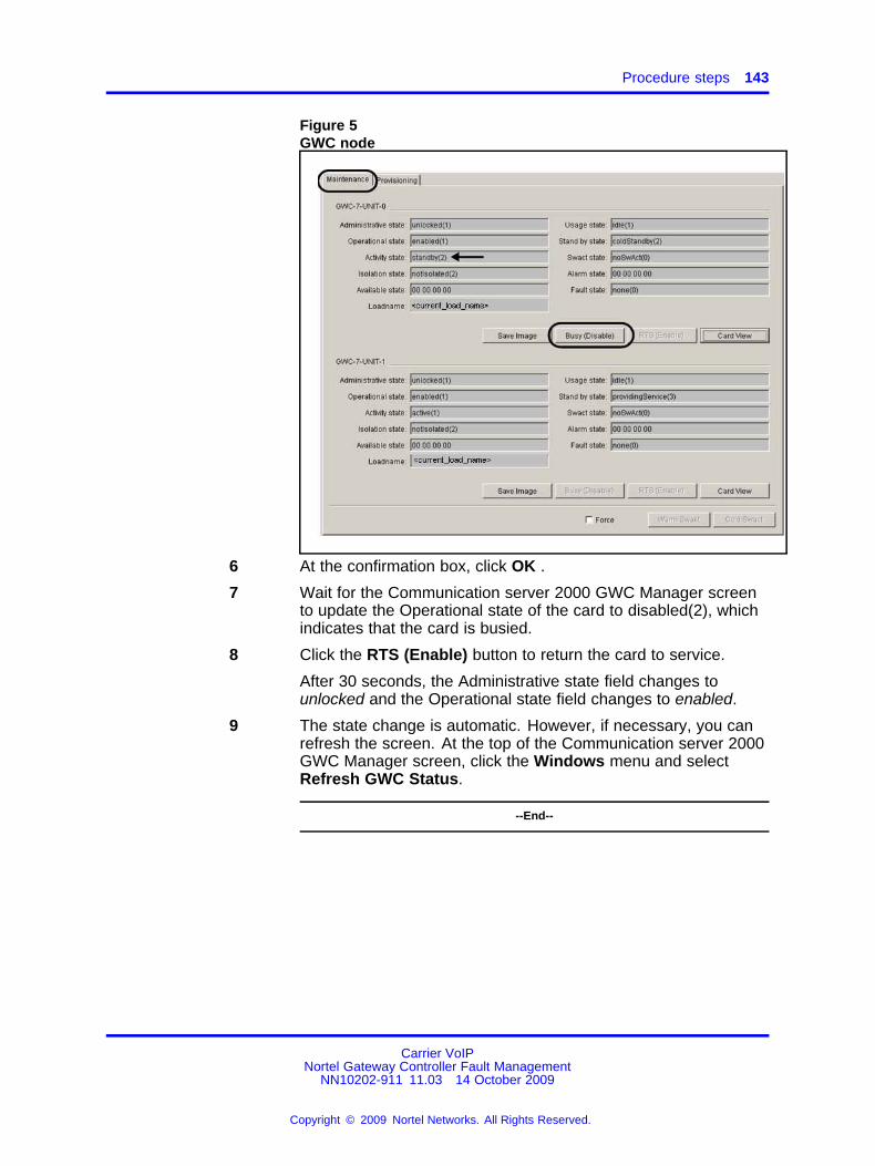
Procedure steps 143
Figure 5GWC node
6 At the confirmation box, click OK .
7 Wait for the Communication server 2000 GWC Manager screento update the Operational state of the card to disabled(2), whichindicates that the card is busied.
8 Click the RTS (Enable) button to return the card to service.
After 30 seconds, the Administrative state field changes tounlocked and the Operational state field changes to enabled.
9 The state change is automatic. However, if necessary, you canrefresh the screen. At the top of the Communication server 2000GWC Manager screen, click the Windows menu and selectRefresh GWC Status.
--End--
Carrier VoIPNortel Gateway Controller Fault Management
NN10202-911 11.03 14 October 2009
Copyright © 2009 Nortel Networks. All Rights Reserved.
.

144 Fault clearing procedures
Replacing and re-provisioning a GWC card
Use this procedure when Nortel support personnel instructs you to replacea faulty GWC card and automatically provision the replacement card withthe provisioning data of the previous card. During this process, the systemassigns a new media access control (MAC) address to the replacementcard but all other card information, including IP addresses, port addresses,gateway addresses, and load paths, remain unchanged.
This procedure does not provide instructions to make services provisioningchanges to a GWC card, such as changing the service profile type of aGWC node. If changes to the GWC node provisioning are necessary,use the CS 2000 GWC Manager to busy the cards and re-provisionnode information. For more information, see Nortel Gateway ControllerConfiguration ( (NN10205-511)).
CAUTIONMCPN750 card does not support the following GWC serviceprofiles: AUDCNTL_RMGC, AUDCNTL_RMGCINTL,BICC, VRDN, VRDNINTL, H.323_INTL_V2, H.323_NA_V2,LARGE_LINEINTL_V2, LARGE_LINENA_V2, LINE_TRUNK_AUD_INTL, LINE_TRUNK_AUD_NA, SIP_T, SIP_TINTL,SMALL_LINEINTL_V2, SMALL_LINENA_V2
If the GWC node is configured with one of these profiles, do notreplace the faulty card with an MCPN750 card. Otherwise, thecard will be locked and will not provide service.
Prerequisites• If the card is not already busied (disabled), busy the card. If required,
see procedure "Busying a GWC node" in Nortel Gateway ControllerConfiguration ( (NN10205-511)).
Procedure steps
Step Action
At the CS 2000 SAM21 Manager client1 Right-click the card the card that you need to replace and select
Card View.
Carrier VoIPNortel Gateway Controller Fault Management
NN10202-911 11.03 14 October 2009
Copyright © 2009 Nortel Networks. All Rights Reserved.
.
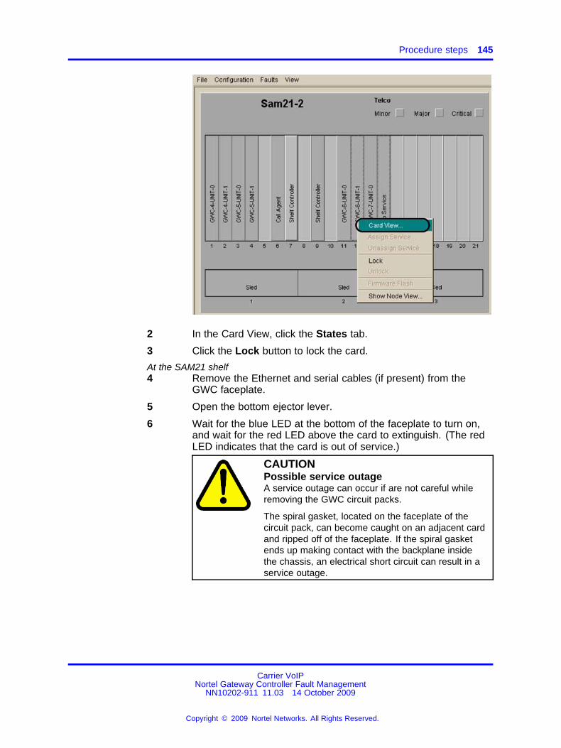
Procedure steps 145
2 In the Card View, click the States tab.
3 Click the Lock button to lock the card.
At the SAM21 shelf4 Remove the Ethernet and serial cables (if present) from the
GWC faceplate.
5 Open the bottom ejector lever.
6 Wait for the blue LED at the bottom of the faceplate to turn on,and wait for the red LED above the card to extinguish. (The redLED indicates that the card is out of service.)
CAUTIONPossible service outageA service outage can occur if are not careful whileremoving the GWC circuit packs.
The spiral gasket, located on the faceplate of thecircuit pack, can become caught on an adjacent cardand ripped off of the faceplate. If the spiral gasketends up making contact with the backplane insidethe chassis, an electrical short circuit can result in aservice outage.
Carrier VoIPNortel Gateway Controller Fault Management
NN10202-911 11.03 14 October 2009
Copyright © 2009 Nortel Networks. All Rights Reserved.
.

146 Fault clearing procedures
CAUTIONStatic electricity damageWear an electrostatic discharge (ESD) groundingwrist strap connected to the SAM21 Shelf Cabinetwhen handling a GWC card. The strap protects thecard against damage caused by static electricity.
7 Press both ejector levers until card is ejected from the shelf.
8 Examine the new circuit pack before inserting it into the SAM21chassis to ensure that the spiral gasket is seated and not loose.
9 Hold the replacement GWC card by the latches and insert thecard into the shelf. Do not push on the faceplate to seat thecard.
Carrier VoIPNortel Gateway Controller Fault Management
NN10202-911 11.03 14 October 2009
Copyright © 2009 Nortel Networks. All Rights Reserved.
.

Procedure steps 147
10 Secure the card by tightening the captive screws at the top andbottom of the panel.
11 Replace the cables on the GWC card faceplate.
At the CS 2000 SAM21 Manager client12 Wait for a card icon with a hashed outline to appear in the shelf
view.
On insertion of the new card, the system automatically provisionsthe new card with the old card’s provisioning information.
The system assigns a new MAC address to the new card.
The CS 2000 SAM21 Manager displays the card type(MCPN905, MCPN750, or CPCI6115) and the correspondingmemory size in the Equip tab of the card view.
13 If the provisioning data for the replacement card is correct, theprocedure is complete.
If the provisioning data for the replacement card is not correct,go to the next step.
14 Open the Card View for the new card and click the Provisioningtab.
Carrier VoIPNortel Gateway Controller Fault Management
NN10202-911 11.03 14 October 2009
Copyright © 2009 Nortel Networks. All Rights Reserved.
.
148 Fault clearing procedures
15 Click the Modify button.
16 Enter the new or changed provisioning data, then click the Savebutton.
You do not need to type the load name. Click the Get LoadFiles button and select the required load from the drop-down list.
17 Click the States tab.
18 Click the Unlock button to unlock the card.
19 Observe the History window to ensure that the card boot loadedand unlocked successfully.
--End--
Carrier VoIPNortel Gateway Controller Fault Management
NN10202-911 11.03 14 October 2009
Copyright © 2009 Nortel Networks. All Rights Reserved.
.

149.
Alarms and logs referenceThis section provides information about Gateway Controller (GWC)service-related alarms, including appropriate actions to diagnose andresolve the alarm condition.
This section also includes reference information related to V5.2 audit logsand to Kerberos, IPSec, and IKE security logs. For all other GWC logreport descriptions, see Nortel Carrier Voice over IP Fault ManagementLogs Reference Volume 2 ( (NN10275-909v2)).
• “GWC service alarms” (page 150)
• “GWC V5.2 audit logs” (page 166)
• “IPSec and IKE security logs” (page 170)
• “Kerberos logs” (page 177)
• “GWC security logs” (page 182)
Carrier VoIPNortel Gateway Controller Fault Management
NN10202-911 11.03 14 October 2009
Copyright © 2009 Nortel Networks. All Rights Reserved.
.
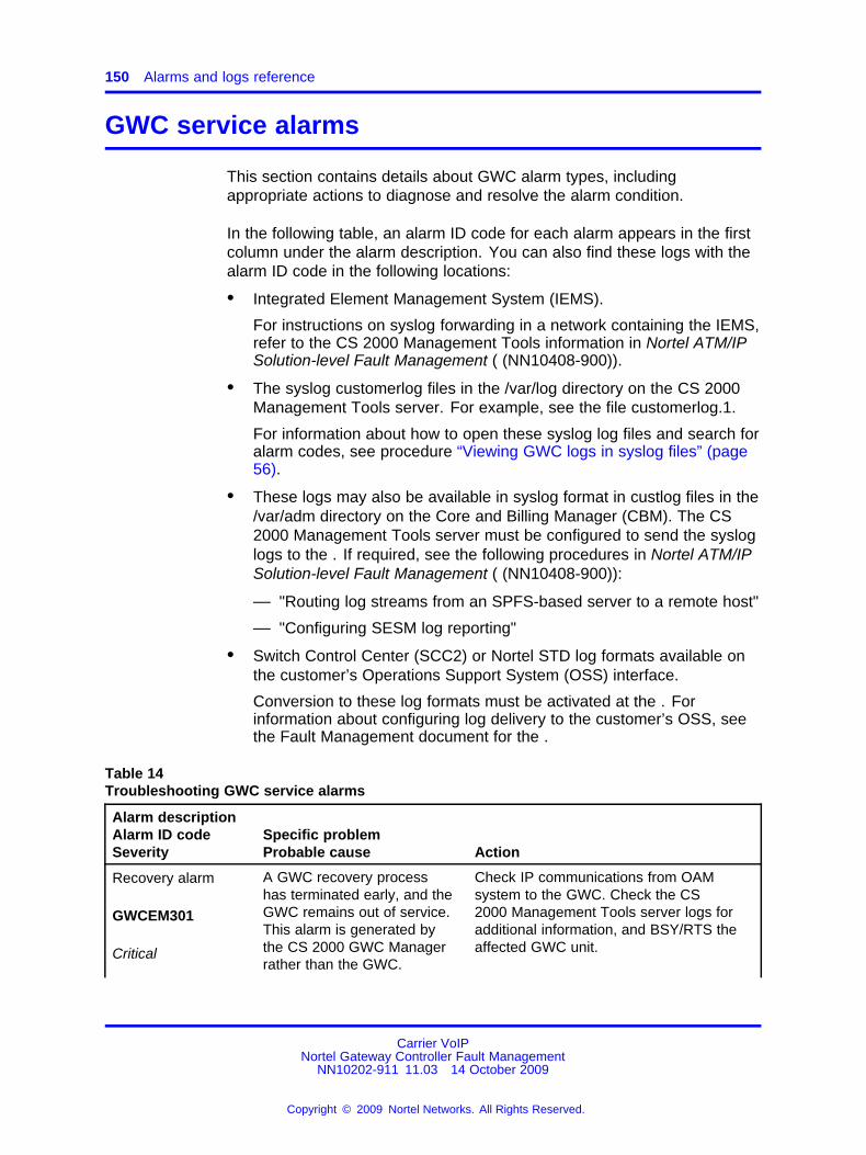
150 Alarms and logs reference
GWC service alarms
This section contains details about GWC alarm types, includingappropriate actions to diagnose and resolve the alarm condition.
In the following table, an alarm ID code for each alarm appears in the firstcolumn under the alarm description. You can also find these logs with thealarm ID code in the following locations:
• Integrated Element Management System (IEMS).
For instructions on syslog forwarding in a network containing the IEMS,refer to the CS 2000 Management Tools information in Nortel ATM/IPSolution-level Fault Management ( (NN10408-900)).
• The syslog customerlog files in the /var/log directory on the CS 2000Management Tools server. For example, see the file customerlog.1.
For information about how to open these syslog log files and search foralarm codes, see procedure “Viewing GWC logs in syslog files” (page56).
• These logs may also be available in syslog format in custlog files in the/var/adm directory on the Core and Billing Manager (CBM). The CS2000 Management Tools server must be configured to send the sysloglogs to the . If required, see the following procedures in Nortel ATM/IPSolution-level Fault Management ( (NN10408-900)):
— "Routing log streams from an SPFS-based server to a remote host"
— "Configuring SESM log reporting"
• Switch Control Center (SCC2) or Nortel STD log formats available onthe customer’s Operations Support System (OSS) interface.
Conversion to these log formats must be activated at the . Forinformation about configuring log delivery to the customer’s OSS, seethe Fault Management document for the .
Table 14Troubleshooting GWC service alarms
Alarm descriptionAlarm ID codeSeverity
Specific problemProbable cause Action
Recovery alarm
GWCEM301
Critical
A GWC recovery processhas terminated early, and theGWC remains out of service.This alarm is generated bythe CS 2000 GWC Managerrather than the GWC.
Check IP communications from OAMsystem to the GWC. Check the CS2000 Management Tools server logs foradditional information, and BSY/RTS theaffected GWC unit.
Carrier VoIPNortel Gateway Controller Fault Management
NN10202-911 11.03 14 October 2009
Copyright © 2009 Nortel Networks. All Rights Reserved.
.

Procedure steps 151
Alarm descriptionAlarm ID codeSeverity
Specific problemProbable cause Action
Specific problem:Functionality not supported.
This problem occurs when theGWC load is incorrect.
If the GWC load is incorrect, change theload, then lock and unlock the GWC card.
Active unit disabled
GWC300
Critical
Specific problem:Indicates that a unit is outof service: Service is notavailable.
Probable cause:the lack of availability of theunderlying resource.
This alarm reports that the unit is not inservice (Operational state of "disabled"). Ifthe Administrative state is "unlocked" andthe Usage state is "busy" this indicatesthe unit is trying to recover itself to an inservice state.
When both units are out of service,the active unit must recover before thestandby unit will.
Check the following:
• Whether the unit is manually lockedout of service (Administrative state of"locked").
• Alarms that may indicate a problem onthe unit preventing it from returning toservice.
• Other state indicators which mayindicate problems, such as:
— Isolation state of "isolated"
— Availability state of "offLine"
• Logs which may also indicate a failureof a step in the process of recoveringthe unit.
Carrier VoIPNortel Gateway Controller Fault Management
NN10202-911 11.03 14 October 2009
Copyright © 2009 Nortel Networks. All Rights Reserved.
.

152 Alarms and logs reference
Alarm descriptionAlarm ID codeSeverity
Specific problemProbable cause Action
Specific problem:Indicates that a unit hasinvalid GWC Profile Data:Service is not available.
Probable cause:A configuration orcustomization error.
Check the profile data for the unit and doone of the following:
- Change to another profile.
- Reconfigure the GWC unit softwareor CS 2000 GWC Manager software toremove the incompatibility.
Then RTS the unit.
Standby unitdisabled
GWC301
Major
Specific problem:Unit is out of service - Serviceis not available.
Probable cause:The lack of availability of theunderlying resource.
This alarm reports that the unit is not inservice (Operational state of "disabled"and Administrative state is "unlocked").The unit is system busy (SysB). If theAdministrative state is "unlocked" and theUsage state is "busy" this indicates the unitis trying to recover itself to an in servicestate.
When both units are out of service,the active unit must recover before thestandby unit will.
Check the following:
• alarms that may indicate a problem onthe unit preventing it from returning toservice
• other state indicators which mayindicate problems, such as:
— isolation state of "isolated"
— for the standby unit, availabilitystate of "degraded"
— availability state of "offLine"
• logs which may also indicate a failureof a step in the process of recoveringthe unit
Carrier VoIPNortel Gateway Controller Fault Management
NN10202-911 11.03 14 October 2009
Copyright © 2009 Nortel Networks. All Rights Reserved.
.

Procedure steps 153
Alarm descriptionAlarm ID codeSeverity
Specific problemProbable cause Action
Standby unit disable
GWC301
Minor
Specific problem:Unit is out of service - Serviceis not available.
Probable cause:The lack of availability of theunderlying resource.
This alarm reports that the unit is not inservice (Operational state of "disabled"and Administrative state is "locked").The unit is manually busy (ManB). If theAdministrative state is "unlocked" and theUsage state is "busy" this indicates the unitis trying to recover itself to an in servicestate.
When both units are out of service,the active unit must recover before thestandby unit will.
Check the following:
• alarms that may indicate a problem onthe unit preventing it from returning toservice
• other state indicators which mayindicate problems, such as:
— isolation state of "isolated"
— for the standby unit, availabilitystate of "degraded"
— availability state of "offLine"
• logs which may also indicate a failureof a step in the process of recoveringthe unit
Specific problem:Unit out of service - invalidGWC Profile Data.
Probable cause:Configuration or customizationerror.
Check the profile data for the unit and doone of the following:
- Change to another profile.
- Reconfigure the GWC unit softwareor CS 2000 GWC Manager software toremove the incompatibility.
Then, RTS the unit.
Carrier VoIPNortel Gateway Controller Fault Management
NN10202-911 11.03 14 October 2009
Copyright © 2009 Nortel Networks. All Rights Reserved.
.

154 Alarms and logs reference
Alarm descriptionAlarm ID codeSeverity
Specific problemProbable cause Action
Corecommunication lost
GWC302
Major, Minor
Specific problem:No response received to Coreheartbeat messages fromactive GWC unit.
Probable cause:LAN error.
Clears automatically after a Core ornetwork outage clears. Otherwise, verifythat the node number and Core SideIP address is correct for the GWC tocommunicate with the Core.
Mate unit communication lost
GWC303
Major, Minor
Specific problem:No response received to mateunit heartbeat messages.
Probable cause:LAN error.
Cleared by restoring communication fromthe CS 2000 GWC Manager to the GWCunit. Do this by unlocking the GWC at theCS 2000 SAM21 Manager. Also, verifythat the Ethernet cable is connected, andthat the GWC is setup to use the correctnode number.
Communication witha gateway is down
GWC304
Major
Specific problem:Communication with gateway<Gatewayname> is down.
Probable cause:The underlying resource is notavailable.
’Gateway’ is defined as largegateway or audio gateway(e.g. PVG, H.323 gatewaywith 64 or more endpoints,MG 9000, UAS).
Cleared by restoring communication to themanaged gateway. Do this by verifying theavailability of the gateway, and comparingthe configuration data at the gateway andthe CS 2000 GWC Manager (IP address,protocol/version, etc.).
This is a test alarmgenerated frompmdebug interface
GWC305
Critical, Major, orMinor
Specific problem:Alarms test from debuginterface.
Probable cause:Unspecified reason.
Cleared from pmdebug command (not acustomer interface) or with a GWC reload.
Carrier VoIPNortel Gateway Controller Fault Management
NN10202-911 11.03 14 October 2009
Copyright © 2009 Nortel Networks. All Rights Reserved.
.

Procedure steps 155
Alarm descriptionAlarm ID codeSeverity
Specific problemProbable cause Action
DQoS/COPSconnection failure
GWC306
Major
Specific problem:A DQoS connection <ConnName@node_ip_address> hasfailed - attempting recovery.
Probable cause:Communications subsystemfailure.
See “Fault management in aDQoS network” (page 14) fordetails about what happenswhen a DQoS connectionfails.
The DQoS connection loss alarmis cleared by DCCNXMGR (usingDCALARM) when the connection isreestablished or the connection is deletedby provisioning.
DQoS/COPSconnection failure
GWC306
Critical
Specific problem:Connection failure alarmthreshold - see customer logdetails
Probable cause:Communications subsystemfailure.
See “Fault management in aDQoS network” (page 14) fordetails about what happenswhen a DQoS connectionfails.
This alarm is generated when the alarmthreshold is exceeded (more than 21failure alarms). In addition to this criticalalarm, each subsequent failing node alsogenerates a customer log GWC503.When the number of failures decreases tobelow 12, the critical alarm is cleared. Atthis point, if log GWC503 was generated,the system generates log GWC502.
For the description of logs GWC502 andGWC503, see Nortel ATM/IP Solution-levelFault Management ( (NN10408-900)).
Element Managercommunicationfailure
GWC307
Major
Specific problem:CS 2000 GWC Managerindicates provisioned datamismatched in this unit.
Probable cause:Communications subsystemfailure
Cleared with a Busy/RTS of GWC unit.
Carrier VoIPNortel Gateway Controller Fault Management
NN10202-911 11.03 14 October 2009
Copyright © 2009 Nortel Networks. All Rights Reserved.
.

156 Alarms and logs reference
Alarm descriptionAlarm ID codeSeverity
Specific problemProbable cause Action
Specific problem:CS 2000 GWC Manager notresponding, provisioned dataloaded from local Flash.
Probable cause:Communications subsystemfailure
Restore communication with the CS 2000GWC Manager. Determine if the CS 2000GWC Manager is down or disconnected,or both. Determine if the GWC has beensetup to use the wrong IP address for theCS 2000 GWC Manager at the CS 2000SAM21 Manager.
Flash memory error
GWC308
Minor
Specific problem:Erase of flash sector failed.
Probable cause:Equipment malfunction.Flash life span exceeded; thenumber of writes to flash hasexceeded the recommendedor intended limit.
Cleared with hardware replacement.
SA_PERCENTAGE_USAGE
GWC309
Minor
This alarm does notapply to the WirelineUniversal PacketAccess (UA-AAL1)solution.
Specific problem:The number of IPSec securityassociations (that is, secureconnections) reached themaximum supported number.
Probable cause:Resource at or nearingcapacity
This is an information alarm. Reportthis alarm with details to your next levelof support. Note that the alarm clearsautomatically as SA usage decreases.
Provisioned GWCProfile not yetactivated
GWC311
Warning
Specific problem:GWC profile loaded intoFlash will activate on the nextreload. A New GWC Profilehas been loaded to GWCFLASH by the CS 2000 GWCManager, but the GWC is stillusing the old Profile.
Probable cause:Configuration or customizationerror.
Cleared with a GWC reload.
Carrier VoIPNortel Gateway Controller Fault Management
NN10202-911 11.03 14 October 2009
Copyright © 2009 Nortel Networks. All Rights Reserved.
.

Procedure steps 157
Alarm descriptionAlarm ID codeSeverity
Specific problemProbable cause Action
QoS collectionapplication (QCA)connection failure
GWC312
Major (partialoutage)
Specific problem:QCA connection<ConnName> has failed -attempting recovery.
Probable cause:Communications subsystemfailure.
No reports are lost since a back up serveris collecting them.
Check the following:
1. Ensure that the QCA contains thecorrect properties (port, IP address).Check that the QCA is properlyprovisioned using the CS 2000Management Tools.
2. Use the ping command to see if youcan reach the QCA server. If youcannot reach the server, there may bea problem in the network.
3. Verify that there is no memoryexhaustion on the QCA server.
4. Restart the QCA application on theserver to bring up the links.
5. Try connecting to a QCA on anotherCS 2000 Management Tools server.
QCA connectionfailure
GWC312
Critical (total outage)
Specific problem:QCA connection<ConnName> has failed -attempting recovery.
Probable cause:Communications subsystemfailure.
Check the following:
1. Ensure that the QCA contains thecorrect properties (port, IP address...).Check that the QCA is properlyprovisioned using the CS 2000Management Tools.
2. Use the ping command to see if youcan reach the QCA server. If youcannot reach the server, there may bea problem in the network.
3. Verify that there is no memoryexhaustion on the QCA server.
4. Restart the QCA application on theserver to bring up the links.
5. Try connecting to a QCA on anotherCS 2000 Management Tools server.
Carrier VoIPNortel Gateway Controller Fault Management
NN10202-911 11.03 14 October 2009
Copyright © 2009 Nortel Networks. All Rights Reserved.
.

158 Alarms and logs reference
Alarm descriptionAlarm ID codeSeverity
Specific problemProbable cause Action
RMGC overloaded
GWC313
Major
Specific problem:RMGC can’t process allincoming requests.
Probable cause:Resource at or nearingcapacity.
The RMGC is temporarily overloaded Thealarm will clear itself once the RMGC isable to process requests again. Gatewayskeep sending requests until they get aresponse. So, once the overload clears,gateways will be able to register withoutany further intervention.
If this alarm is seen regularly or does notclear, then this is an indication that thereis insufficient RMGC processing capacityin the office. Consider commissioninganother RMGC.
Location IDreportingconnection failure
GWC314
Major
Specific problem:Location ID reportingconnection <IP address>has failed - attempting torecover.
Probable cause:Communications subsystemfailure - destination notavailable.
Clear the alarm condition using one of thefollowing approaches:
• Reestablish the connection to thelocation recipient.
• Disable the location ID reportingapplication.
• Busy/RTS the GWC unit.
External hostinterface signal loss
GWC315
Critical (>50% loss)
Major (>20% loss)
Minor (any signalloss)
Specific problem:Small GWs in disabled state
Probable cause:Signal loss - alarm based onnumber of GWs out of servicecompared with number ofGWs provisioned
Logs (GWC502) indicate a small line GWgoing out of service and coming backinto service. GWs are considered to beout of service when heartbeat messagesbetween the GW and GWC are lost.
Use the new small gateway OMs to checkhow many small line GWs are out ofservice.
Use the logs to identify which GWs needattention.
Carrier VoIPNortel Gateway Controller Fault Management
NN10202-911 11.03 14 October 2009
Copyright © 2009 Nortel Networks. All Rights Reserved.
.
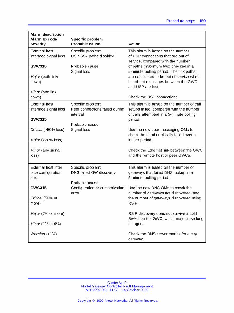
Procedure steps 159
Alarm descriptionAlarm ID codeSeverity
Specific problemProbable cause Action
External hostinterface signal loss
GWC315
Major (both linksdown)
Minor (one linkdown)
Specific problem:USP SS7 paths disabled
Probable cause:Signal loss
This alarm is based on the numberof USP connections that are out ofservice, compared with the numberof paths (maximum two) checked in a5-minute polling period. The link pathsare considered to be out of service whenheartbeat messages between the GWCand USP are lost.
Check the USP connections.
External hostinterface signal loss
GWC315
Critical (>50% loss)
Major (>20% loss)
Minor (any signalloss)
Specific problem:Peer connections failed duringinterval
Probable cause:Signal loss
This alarm is based on the number of callsetups failed, compared with the numberof calls attempted in a 5-minute pollingperiod.
Use the new peer messaging OMs tocheck the number of calls failed over alonger period.
Check the Ethernet link between the GWCand the remote host or peer GWCs.
External host interface configurationerror
GWC315
Critical (50% ormore)
Major (7% or more)
Minor (1% to 6%)
Warning (<1%)
Specific problem:DNS failed GW discovery
Probable cause:Configuration or customizationerror
This alarm is based on the number ofgateways that failed DNS lookup in a5-minute polling period.
Use the new DNS OMs to check thenumber of gateways not discovered, andthe number of gateways discovered usingRSIP.
RSIP discovery does not survive a coldSwAct on the GWC, which may cause longoutages.
Check the DNS server entries for everygateway.
Carrier VoIPNortel Gateway Controller Fault Management
NN10202-911 11.03 14 October 2009
Copyright © 2009 Nortel Networks. All Rights Reserved.
.

160 Alarms and logs reference
Alarm descriptionAlarm ID codeSeverity
Specific problemProbable cause Action
External hostinterface protocolerror
GWC315
Major (both links notactive)
Minor (one link notactive)
Specific problem:USP SS7 path not active
Probable cause:Communications protocolerror
This alarm is based on the number of USPconnections that have heartbeat messagesbut are not active in a 5-minute pollingperiod.
A major alarm affects some callprocessing; a minor alarm causes aredundancy error.
Check the USP configuration to the GWC.
External communication interface
GWC315
Critical (>50%proxies disabled)
Major (>20% proxiesdisabled)
Minor (any mediaproxies disabled)
Specific problem:Media proxies in disabledstate
Probable cause:Signal loss - alarm basedon number of media proxiesout of service compared withnumber of media proxiesprovisioned
Media proxies are considered to be outof service when they fail to respondto messages sent from the GWC, andreturned to service when the GWCreceives the regular RSIP message. Thealarm is raised as a media proxy goesout of service, and cleared when it comesback into service.
Use the media proxy OMs to check howmany media proxies are out of service inany 5-minute polling period.
Use the RTP Portal EM to identify whichmedia proxies need attention.
This alarm and the associated OMs givethe GWC view of calls, as opposed to themedia proxy view.
PreSwact auditfailure
GWC317
Major
Specific problem:PreSwact audit failed for twoconsecutive cycles
Probable cause:
• monitored base resourcereaches the threshold level
• monitored applicationresource reaches thethreshold level
Check the alarm text to see whichcomponent has failed.The alarm clears when you clear the errorcondition.
If required, you can use Swact force toforce a manual warm Swact.
Carrier VoIPNortel Gateway Controller Fault Management
NN10202-911 11.03 14 October 2009
Copyright © 2009 Nortel Networks. All Rights Reserved.
.

Procedure steps 161
Alarm descriptionAlarm ID codeSeverity
Specific problemProbable cause Action
• data synchronizationmismatch (SESM, GWCflash, GWC RAM)
• standby unit is jammedand prevented from takingup the activity
The preSwact audit runs at a frequency of 40 seconds and with priority 6.
A second occurrence of the same error condition does not raise an alarm.
No alarm is raised if the preSwact audit fails while patching is in progress in the inactive unit.
AutonomousSWACT initiated
GWC318
Critical
Specific problem:<Element Name> Nocommunication withassociated media gateway(s)
Probable cause: Underlyingresource unavailable.
This alarm indicates that thesystem attempts to restorecommunication with theassociated media gateways.
Check the related network componentmanagers to identify failures within thenetwork.
The alarm clears automatically when amanual SWACT back to the original activeunit is performed.
You can also manually clear this alarmonce the problem on the original activeunit is solved. Follow procedure Clearingthe GWC318 critical alarm manually .
GWC communication loss withassociated mediagateway(s)
GWC319
Critical
Specific problem:<Element Name> Nocommunication withassociated media gateway(s)
Probable cause: Underlyingresource unavailable.
Check the related network componentmanagers to identify failures within thenetwork.
This alarm clears when the GWCdetects communication with at leastone associated gateway. It also clearswhen the GWC automatically or manuallyswitches activity, but it is raised again onthe newly active unit if communication isstill lost with all associated gateways.
IKE/IPSec
GWC320
GWC320 alarms indicate an IKE/IPSec-related problems. See the SpecificProblem: field to check the reason for generating this alarm.
Each specific alarm may have an associated security log, which providesadditional details about the problem. .
Carrier VoIPNortel Gateway Controller Fault Management
NN10202-911 11.03 14 October 2009
Copyright © 2009 Nortel Networks. All Rights Reserved.
.

162 Alarms and logs reference
Alarm descriptionAlarm ID codeSeverity
Specific problemProbable cause Action
GWC320
Critical - certificateexpires within 5 days
Major - certificateexpires within 15days
Minor - certificateexpires within 30days
Specific problem:One or more certificates inset number <x> (device certserial # <xxx>) are expiring.An outage may occur ifan IKE connection policyis using these certificates.At the GWCEM, pleaseverify the expiry dates forcertificates in set number <x>-- <GWC_IP_address>
where
<x> is the set numberof the [IKEcertificates]panel
<xxx> is the serialnumber ofthe expiringcertificate
Probable cause:Key expired
This alarm indicates that an IKE certificateis expiring soon and the GWC Managerhas not obtained a new certificate from theCertificate Manager. Service disruptionmay occur when the certificate expires.
For information about how to clear thisalarm, see procedure “Recovery of theGWC320 certificate expiry alarm” in NortelCVoIP IPSec Service Configuration ((NN10453-100)).
GWC320
Critical
Specific problem:One or more certificates inset number <x> (device certserial # <xxx>) are expired.An outage will occur if anIKE connection policy isusing these certificates.At the GWCEM, pleaseverify the expiry dates forcertificates in set number <x>-- <GWC_IP_address>
where
<x> is the set numberof the [IKEcertificates]panel
<xxx> is the serialnumber of
This alarm indicates that an IKE certificateis expired and the GWC Manager hasnot obtained a new certificate from theCertificate Manager. Service disruption willoccur when the certificate expires.
For information about how to clear thisalarm, see procedure “Recovery of theGWC320 certificate expiry alarm” in NortelCVoIP IPSec Service Configuration ((NN10453-100)).
Carrier VoIPNortel Gateway Controller Fault Management
NN10202-911 11.03 14 October 2009
Copyright © 2009 Nortel Networks. All Rights Reserved.
.

Procedure steps 163
Alarm descriptionAlarm ID codeSeverity
Specific problemProbable cause Action
the expiringcertificate
Probable cause:Key expired
GWC320
Critical
Specific problem:Phase 1 SA failure --<remote_gateway_IP_address>
Probable cause:Underlying resourceunavailable
This alarm indicates that a Phase 1negotiation failed. This alarm is the resultof an outage.
To clear this alarm, complete procedureClearing GWC320 Phase 1 SA failurealarm.
GWC320
Critical
Specific problem:Phase 2 SA failure --<remote_gateway_IP_address>
Probable cause: Underlyingresource unavailable
This alarm indicates that a Phase 2negotiation failed. This alarm is the resultof an outage.
To clear this alarm, complete procedureClearing GWC320 Phase 2 SA failurealarm.
GWC320
Critical
Specific problem:Private key doesn’t matchGWC certificate in set number<x>(device cert serial # <xxx>-- <GWC_IP_address>
where
<x> is the set numberof the [IKEcertificates]panel
<xxx> is the serialnumber of thecertificate
Probable cause:Unexpected Information
This alarm may indicate an outage.
Contact your next level of support.
There are no security logs associated withthis specific problem.
Carrier VoIPNortel Gateway Controller Fault Management
NN10202-911 11.03 14 October 2009
Copyright © 2009 Nortel Networks. All Rights Reserved.
.

164 Alarms and logs reference
Alarm descriptionAlarm ID codeSeverity
Specific problemProbable cause Action
GWC320
Critical
Specific problem:Invalid Subject AlternativeName in GWC certificateset number <x> (devicecert serial # <xxx>) --<GWC_IP_address>
where
<x> - is the set numberof the [IKEcertificates]panel
<xxx> is the serialnumber of thecertificate
Probable cause:unexpectedInformation
This alarm indicates that the SubjectAlternative Name in the GWC certificatedoes not match the provisioned IP addressfor the GWC certificate. This may indicatea data or communication problem betweenthe GWC and the GWC Manager.
Contact your next level of support.
Ethernet/IP Errors
GWC321
Major
Specific problem:Auto-negotiation disabled onEthernet link.
Probable cause:Configuration or customizationerror
Enable the auto-negotiation capabilityon the Ethernet Routing Switch 8600. Ifrequired, see the Ethernet Routing Switch8600 configuration documentation.
A subsystemoverloaded
GWC322
Major - SNMPmessage ratecrossed the PanicLevel
Warning - SNMPmessage ratecrossed the WarningLevel
Specific problem:
• for major alarms:
SNMP message rateexceeded recommendedmaximum
• for warning alarms:
SNMP message rate is closeto recommended maximums
Probable cause:Threshold crossed
Reduce the SNMP traffic level.
Carrier VoIPNortel Gateway Controller Fault Management
NN10202-911 11.03 14 October 2009
Copyright © 2009 Nortel Networks. All Rights Reserved.
.

Procedure steps 165
Alarm descriptionAlarm ID codeSeverity
Specific problemProbable cause Action
Communication witha gateway is down
GWC501
Major
Specific problem:Gateway failed to respond toheartbeat/audit
Probable cause:The underlying resource is notavailable.
’Gateway’ is defined as smallgateway(e.g. Askey/Mediatrix linegateway, Arris/Motorolagateway, H.323 gateway withless than 64 endpoints).
Cleared by restoring communication to themanaged gateway. Do this by verifying theavailability of the gateway, and comparingthe configuration data at the gateway andthe CS 2000 GWC Manager (IP address,protocol/version, etc.).
Data inconsistencybetween GWCEMand Session Server
Minor
Specific problem:Data inconsistency betweenGWCEM and Session Server
Probable cause:Depends on the condition thatcaused the alarm.
Examples: "Data Audit run butdata not fully synchronized","Setting the Call Agent IDhas resulted in data changes,which need to be propagatedto the Session Server. Runthe CS2KSS EM DataIntegrity Audit", "Failed torollback ’add zone’ commandfrom Database", "Failedto rollback ’delete zone’command.
For all cases other than when the DataAudit fails, run the CS2KSS Data IntegrityAudit. If the data audit fails, investigate thereason (for example, connection failure,problem with the data on the CS2KSSEM, and so on) and manually correct theproblem.
Carrier VoIPNortel Gateway Controller Fault Management
NN10202-911 11.03 14 October 2009
Copyright © 2009 Nortel Networks. All Rights Reserved.
.

166 Alarms and logs reference
GWC V5.2 audit logs
This section describes troubleshooting activities on the GWC or a relatedcomponent in response to a particular V5.2 fault log.
There are a number of GWC-related log types that are specific to V5.2lines maintenance. V5.2 audit logs are generated to capture regularmaintenance test results made to associated V5.2 media gateways andaccess nodes. The BCC audit verifies a possible mismatch between GWCand AN while the V5CC audits verify a possible mismatch CM and GWC.See the relationship as follows:
• V5 BCC Audit
• V5CC Audit
— V5 Interface Audit
— V5 Link Audit
— V5 C-channels Audit
— V5 Data Link Audit
Use the following table to review the details of the log type displayed byyour log utility and formulate the appropriate actions to diagnose and repairthe problem.
For more information about V5.2 logs, see the appropriate V5.2 logdescription in Nortel Carrier Voice over IP Fault Management LogsReference Volume 2 ( (NN10275-909v2)).
Table 15V5.2 logs
Log type;Problemlogged Reason for failure Details
V5200(BCC Auditfails)
Generated when an AN (accessnode) does not respond to a BCCAudit message.
V5201(BCC Auditmessage)
Generated when an audit messageis sent from the CM to an accessnode.
The BCC audit allows checking of apossible mismatch between GWC andaccess node (AN). It is executed whenthe AN sends a BCC Reject message tothe GWC, upon receiving BCC Allocation.There are several reject causes, which are
Carrier VoIPNortel Gateway Controller Fault Management
NN10202-911 11.03 14 October 2009
Copyright © 2009 Nortel Networks. All Rights Reserved.
.

Procedure steps 167
Log type;Problemlogged Reason for failure Details
V5202(BCC Auditincomplete)
Generated during a BCC (bearerchannel control) audit, when thereturned "Audit Complete" messageincludes the information element"Connection Incomplete".
given in the BCC Reject message. Someof those reject causes will make the GWCsend a BCC Audit to the AN.
• Connection already present at thePSTN user port to a different V5 timeslot (0x83)
• Connection already present at the V5time slot(s) to a different port or ISDNuser port time slot (0x84)
• Connection already present at the ISDNuser port time slot(s) to a different V5time slot(s) (0x85)
• Deallocation cannot be completed dueto V5 time slot(s) data incompatibility(0x88)
• Deallocation cannot be completed dueto port data incompatibility (0x89)
• Deallocation cannot be completed- user port time slot(s) dataincompatibility (0x8A)
V5400(V5CC Audit)
Generated when there is no replyfrom the V5 interface for the V5audit queries during V5CC audit.
V5CC interface audit is the only auditexecuted if an interface in the deactivatedstatus.
The V5CC (channel control) Auditperforms consistency checks for variousinterface, link and line statuses. Whenthe GWC is not in service, when a GWCstartup/activation process takes placeor when in a GWC is in a maintenancein-progress state, a V5CC audit will not beexecuted.
V5 interfaces will be audited in thefollowing order:
• V5 interface audit
• V5 link audit
• V5 c-channel audit
• V5 data link audit
Carrier VoIPNortel Gateway Controller Fault Management
NN10202-911 11.03 14 October 2009
Copyright © 2009 Nortel Networks. All Rights Reserved.
.

168 Alarms and logs reference
Log type;Problemlogged Reason for failure Details
• V5 babbling lines audit
• V5 line state audit
An interface will receive audit queriesevery 10 minutes.
V5401(V5 InterfaceAudit)
Generated when a mismatch isdetected by the CM for a queriedV5 interface on a GWC.
During a V5CC audit, the CM sends a V5interface query to an interface on a GWC,the query message requests the status ofthe interface on the GWC.
The GWC will send a response messageupon receiving a V5 interface querymessage with the status of thecorresponding interface (either ACTor DEACT).
If a mismatch is detected, the CM willrequest the GWC to change the status ofthe interface to that held on the CM.
V5402(V5 Link Audit)
Generated when a mismatch isdetected by the CM for a queriedV5 link on a GWC.
During a V5CC audit, a V5 link audit isperformed. When the GWC sends a replymessage, which contains the status of thelinks, the CM will check the status of thelink carrier and compare it with the statusof a carrier flag.
In case of mismatch of carrier flag, the CMwill send a message to GWC in order toopen or close scanning on the given link,respectively.
V5403(V5C-channelsAudit)
Generated when a mismatch occursbetween the status of the C-channelas recorded in the GWC and in theCM.
The CM sends a V5 C-channel audit to aGWC to request the C-channel informationon the GWC. No action is taken on theGWC side. After receiving the responsemessage from GWC, the CM looks for thefollowing:
• C-channel status mismatch(INSV/OOS)
• C-channel activity mismatch(ACT/STBY)
• C-channel static data mismatch
Carrier VoIPNortel Gateway Controller Fault Management
NN10202-911 11.03 14 October 2009
Copyright © 2009 Nortel Networks. All Rights Reserved.
.

Procedure steps 169
Log type;Problemlogged Reason for failure Details
In all cases of mismatch, the C-channelstatus on the CM will be updated accordingto the status held on the GWC. Noadditional maintenance request is neededupon mismatch detection.
V5404(Data LinkAudit)
Generated when a mismatch occursbetween the status of the data linksas recorded in the GWC and in theCM.
The CM sends a V5 data link auditmessage to a GWC to request a data linkstatus on the GWC. No action is takenon the GWC side. The GWC will send aresponse message which contains thecurrent data link status. The data linkstatus consists of CTRL, PSTN, BCC,LNK_CTRL, PROT1 and PROT2 statuses.
After receiving a response message fromGWC, the CM will look for a mismatch, Incase of mismatch, the appropriate alarmstatus on the CM will be updated accordingto the status of the data link. Additionalmaintenance requests to reset (MANRTS)or block (MANBSY) all V5 lines is sentupon mismatch detection. Log V5404 willbe generated in case of a mismatch.
Carrier VoIPNortel Gateway Controller Fault Management
NN10202-911 11.03 14 October 2009
Copyright © 2009 Nortel Networks. All Rights Reserved.
.

170 Alarms and logs reference
IPSec and IKE security logs
This section describes how to access and understand IPSec and IKEsecurity log reports associated with GWC nodes. These log reportsare stored in the securitylog files in directory /var/log on the CS 2000Management Tools server.
To access these security log reports, follow procedure “Viewing GWC logsin syslog files” (page 56).
To display IPSec and IKE log reports, search for the text string ISAKMPwithin the securitylog files.
FormatThe format for security log reports is as follows:
Selected field descriptionsThe following table explains selected fields in the log report.
Field Value Description
mmm ddhh:mm:ss
alphanumeric The date and time stamp for the logreport.
mmm means three first letters of themonth, for example, Aug.
<IP address> numeric The IP address of the unit device fromwhich the log originated.
<log type> class_security.ver01 Common name for security logs.
ISAKMP_INFOorISAKMP_FAIL
text string Indicates an information-only or aproblem-reporting log.
<log message> alphanumeric character string A description of the conditions orreasons generating the log.For log descriptions and associatedactions, see section “Actions” (page171).
<status> success or failure Indicates whether the operationsucceeded or failed.
<MID> MID=MID_Nortel_MGC_autho.<0016or 0017>
0016 indicates an INFO log. 0017indicates a FAIL log.
Carrier VoIPNortel Gateway Controller Fault Management
NN10202-911 11.03 14 October 2009
Copyright © 2009 Nortel Networks. All Rights Reserved.
.

Actions 171
ActionsRequired action depends on the log description. The following table listssecurity log messages and explanations, and the appropriate actions.
Table 16IPSec and IKE security logs
Log message Explanation and Action
Logs associated with the "Phase 1 SA failure" GWC320 critical alarm:
ATTENTIONService disruptionThe following log reports and the associated alarms are the result of an outage.
To clear these fault conditions, complete procedure “Clearing the GWC320 Phase 1 SA failurealarm” (page 128).
ISAKMP_FAIL IKE phase 1 timeoutexhausted (PHASE 1 <INITIATOR orRESPONDER>, init:<IP>, resp:<IP>)
There is a problem during an IKE Phase 1negotiation and multiple retransmission attemptsfail.
ISAKMP_FAIL IKE payload not formedcorrectly, possible presharedkey mismatch (PHASE 1 INITIATOR,init:<IP>, resp:<IP>)
The system cannot authenticate the remotegateway.
ISAKMP_FAIL IKE payload validationfailed, possible preshared keymismatch (PHASE 1 <INITIATOR orRESPONDER>, init:<IP>, resp:<IP>)
The preshared key configured on the GWCdoes not match the preshared key configuredon the remote gateway.
ISAKMP_FAIL payload malformed,possible pre-shared key mismatch(resp:<IP>, init:<IP>)
The pre-shared key configured on the GWCdoes not match the pre-shared key configuredon the remote gateway.
ISAKMP_FAIL payload malformed(resp:<IP>, init:<IP>)
The system cannot authenticate the remotegateway.
ISAKMP_FAIL No Preferences Match forIKE Phase 1 Negotiation (init:<IP>,resp:<IP>)
IKE preferences configured on the GWC and onthe remote gateway do not match.
ISAKMP_FAIL invalid signature (initIP:<IP>, resp IP:<IP>)
The GWC cannot authenticate the remotegateway.
ISAKMP_FAIL IKE phase 1 signature orcertificate check (PHASE 1 <INITIATORor RESPONDER>, init:<IP>, resp:<IP>)
There is a problem during an IKE Phase 1negotiation and the GWC cannot verify orauthenticate the certificate presented by theremote gateway.
Phase 1 Error: Received a NO_PROPOSAL_CHOSEN message init:<IP>, resp:<IP>)
IKE preferences configured on the GWC and onthe remote gateway do not match.
Phase 1 Error : Received a PAYLOAD_MALFORMED message (init:<IP>,resp:<IP>)
The system cannot authenticate the remotegateway. Check that both sides have the samepreshared key or valid certificates.
Carrier VoIPNortel Gateway Controller Fault Management
NN10202-911 11.03 14 October 2009
Copyright © 2009 Nortel Networks. All Rights Reserved.
.

172 Alarms and logs reference
Table 16IPSec and IKE security logs (cont’d.)
Log message Explanation and Action
Phase 1 Error : Discard PolicyProvisioned (init : <IP>, resp :<IP>)
A Discard Policy is provisioned for this gateway.
Phase 1 Error : Bypass PolicyProvisioned (init : <IP>, resp :<IP>)
A Bypass Policy is provisioned for this gateway.
Phase 1 Error : Kerberos PolicyProvisioned (init : <IP>, resp :<IP>)
A Kerberos Policy is provisioned for thisgateway.
Phase 1 Error while processing SAPayload (init : <init_ip>, resp:<resp_ip>:)
Unable to interpret or parse an IKE exchangemessage. Check the peer for error messages.
Phase 1 Error while processing HASHPayload (init : <init_ip>, resp:<resp_ip>:)
Unable to interpret or parse an IKE exchangemessage. Check the peer for error messages.
Phase 1 Error while processing KEPayload (init : <init_ip>, resp:<resp_ip>:)
Unable to interpret or parse an IKE exchangemessage. Check the peer for error messages.
Phase 1 Error while processing NONCEPayload (init : <init_ip>, resp:<resp_ip>:)
Unable to interpret or parse an IKE exchangemessage. Check the peer for error messages.
Phase 1 Error while processing IDPayload (init : <init_ip>, resp:<resp_ip>:)
Unable to interpret or parse an IKE exchangemessage. Check the peer for error messages.
Phase 1 Error while constructing SAPayload (init : <init_ip>, resp:<resp_ip>:)
Unable to create an IKE exchange message.The most likely cause is insufficient resourceson the GWC. Contact your second level ofsupport.
Phase 1 Error while constructing HASHPayload (init : <init_ip>, resp:<resp_ip>:)
Unable to create an IKE exchange message.The most likely cause is insufficient resourceson the GWC. Contact your second level ofsupport.
Phase 1 Error while constructing KEPayload (init : <init_ip>, resp:<resp_ip>:)
Unable to create an IKE exchange message.The most likely cause is insufficient resourceson the GWC. Contact your second level ofsupport.
Phase 1 Error while constructing NONCEPayload (init : <init_ip>, resp:<resp_ip>:)
Unable to create an IKE exchange message.The most likely cause is insufficient resourceson the GWC. Contact your second level ofsupport.
Carrier VoIPNortel Gateway Controller Fault Management
NN10202-911 11.03 14 October 2009
Copyright © 2009 Nortel Networks. All Rights Reserved.
.
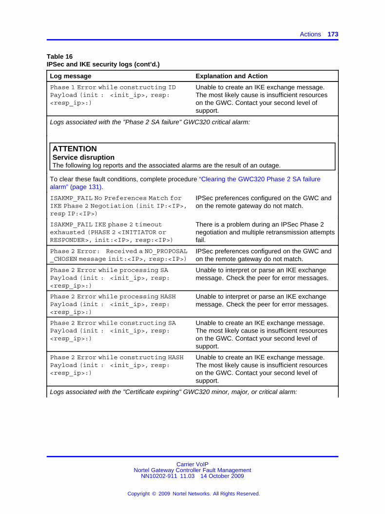
Actions 173
Table 16IPSec and IKE security logs (cont’d.)
Log message Explanation and Action
Phase 1 Error while constructing IDPayload (init : <init_ip>, resp:<resp_ip>:)
Unable to create an IKE exchange message.The most likely cause is insufficient resourceson the GWC. Contact your second level ofsupport.
Logs associated with the "Phase 2 SA failure" GWC320 critical alarm:
ATTENTIONService disruptionThe following log reports and the associated alarms are the result of an outage.
To clear these fault conditions, complete procedure “Clearing the GWC320 Phase 2 SA failurealarm” (page 131).
ISAKMP_FAIL No Preferences Match forIKE Phase 2 Negotiation (init IP:<IP>,resp IP:<IP>)
IPSec preferences configured on the GWC andon the remote gateway do not match.
ISAKMP_FAIL IKE phase 2 timeoutexhausted (PHASE 2 <INITIATOR orRESPONDER>, init:<IP>, resp:<IP>)
There is a problem during an IPSec Phase 2negotiation and multiple retransmission attemptsfail.
Phase 2 Error: Received a NO_PROPOSAL_CHOSEN message init:<IP>, resp:<IP>)
IPSec preferences configured on the GWC andon the remote gateway do not match.
Phase 2 Error while processing SAPayload (init : <init_ip>, resp:<resp_ip>:)
Unable to interpret or parse an IKE exchangemessage. Check the peer for error messages.
Phase 2 Error while processing HASHPayload (init : <init_ip>, resp:<resp_ip>:)
Unable to interpret or parse an IKE exchangemessage. Check the peer for error messages.
Phase 2 Error while constructing SAPayload (init : <init_ip>, resp:<resp_ip>:)
Unable to create an IKE exchange message.The most likely cause is insufficient resourceson the GWC. Contact your second level ofsupport.
Phase 2 Error while constructing HASHPayload (init : <init_ip>, resp:<resp_ip>:)
Unable to create an IKE exchange message.The most likely cause is insufficient resourceson the GWC. Contact your second level ofsupport.
Logs associated with the "Certificate expiring" GWC320 minor, major, or critical alarm:
Carrier VoIPNortel Gateway Controller Fault Management
NN10202-911 11.03 14 October 2009
Copyright © 2009 Nortel Networks. All Rights Reserved.
.

174 Alarms and logs reference
Table 16IPSec and IKE security logs (cont’d.)
Log message Explanation and Action
Certificate is expiring on Year=<yyyy> Month=<mm> Day=<dd>
After an IKE Phase 1 negotiation, if anycertificate in the chain (excluding the root CA)is expiring within 30 days, this failure log isgenerated. If the certificates are not replacedimmediately, there may be a call processingoutage.
This log is associated a GWC320 alarm:
• critical - certificate expires within 5 days
• major - certificate expires within 15 days
• minor - certificate expires within 30 days
If the certificate is expired, this alarmremains, and if any connection policy and IKEauthentication is using this certificate, a "Phase1 SA failure" alarm is also raised.
To clear the "Certificate expiring" alarm,complete procedure “Recovering of theGWC320 certificate expiry alarm” in NortelCVoIP IPSec Service Configuration ((NN10453-100)).
Logs associated with the "Certificate expired" GWC320 critical alarm:
One or more certificates in set number<x> (device cert serial # <xxx>) areexpired
One or more certificates in a set is expired. Anoutage will occur if an IKE connection policy isusing these certificates.
To clear the "Certificate expired" alarm,complete procedure “Recovery of the GWC320certificate expiry alarm” in Nortel CVoIP IPSecService Configuration ( (NN10453-100)).
Logs indicating problems with the Diffie-Hellman (DH) exchange - no associated alarms:
ATTENTIONService disruptionThe following log reports are the result of an outage.
ISAKMP_FAIL IKE Phase 1 keynegotiation failed - DH is NULL(ini:<ip>, resp:<ip>)
The GWC cannot allocate sufficient resources.
Contact your next level of support
Carrier VoIPNortel Gateway Controller Fault Management
NN10202-911 11.03 14 October 2009
Copyright © 2009 Nortel Networks. All Rights Reserved.
.

Actions 175
Table 16IPSec and IKE security logs (cont’d.)
Log message Explanation and Action
ISAKMP_FAIL IKE Phase 1 keynegotiation failed - unable toset peer’s DH pub key (ini:<ip>,resp:<ip>)
The GWC cannot allocate sufficient resources.
Contact your next level of support
ISAKMP_FAIL IKE Phase 1 keynegotiation failed - unable togen DH key pair (ini:<ip>, resp:<ip>)
The GWC cannot allocate sufficient resources.
Contact your next level of support
ISAKMP_FAIL IKE Phase 1 keynegotiation failed - unable tocompute shared secret (ini:<ip>,resp:<ip>)
The GWC cannot allocate sufficient resources.
Contact your next level of support
ISAKMP_FAIL DOI no supported(ini:<ip>, resp:<ip>)
The GWC cannot negotiate a securityassociation with the remote gateway.
Contact your next level of support.
Logs indicating problems with the Phase 1 exchange - no associated alarms:
ATTENTIONService disruptionThe following log reports are the result of an outage.
To clear these fault conditions, complete procedure “Clearing the GWC320 Phase 1 SA failurealarm” (page 128).
ISAKMP_FAIL invalid signature(ini:<ip>, resp:<ip>)
The GWC cannot authenticate the remotegateway.
ISAKMP_FAIL invalid payload(ini:<ip>, resp:<ip>)
The GWC cannot authenticate the remotegateway.
ISAKMP_FAIL invalid hash info(ini:<ip>, resp:<ip>)
The GWC cannot authenticate the remotegateway.
Information-only logs:
Certificate provisioning - validityperiod checked: Certificate<effective or expire> Y/M/D H:M:S:<effective or expiry date and time>
When a certificate is provisioned on the GWC,the GWC checks the certificate effective andexpiry date and generates this log.
When certificate provisioning fails, use this logto determine if the certificate is not effective orhas expired.
There is no associated alarm.
Carrier VoIPNortel Gateway Controller Fault Management
NN10202-911 11.03 14 October 2009
Copyright © 2009 Nortel Networks. All Rights Reserved.
.

176 Alarms and logs reference
Table 16IPSec and IKE security logs (cont’d.)
Log message Explanation and Action
Phase 1 SA Successfully Established(init IP:<IP>, resp IP:<IP>)
This log confirms a successful IKE Phase 1negotiation between the GWC and a remotegateway.
If a GWC320 alarm is generated, it clearsautomatically. No action required.
Phase 2 SA Successfully Established(init IP:<IP>, resp IP:<IP>
This log confirms a successful IPSec Phase 2negotiation between the GWC and a remotegateway.
If a GWC320 alarm is generated, it clearsautomatically. No action required.
Associated OM registersThese log reports have no associated OM registers.
Additional informationNone
Carrier VoIPNortel Gateway Controller Fault Management
NN10202-911 11.03 14 October 2009
Copyright © 2009 Nortel Networks. All Rights Reserved.
.

Action 177
Kerberos logs
This section describes how to access and understand log reportsassociated with the Kerberos application running on the GWC card. Theselog reports are stored in the securitylog files in directory /var/log on theCS 2000 Management Tools server.
To access the Kerberos log reports, follow procedure “Viewing GWC logsin syslog files” (page 56). To display Kerberos log reports, search for thetext string KERBEROS (common name for all Kerberos logs).
You can also access the Kerberos log reports through the IntegratedElement Management System (IEMS). For more information, see NortelIEMS Fault Management ( (NN10334-911)).
FormatThe format for Kerberos log reports is as follows:
Selected field descriptionsThe following table explains selected fields in the log report.
Table 17Log field descriptions
Field Value Description
mmm dd hh:mm:ss alphanumeric The date and time stamp for the log report.
mmm means three first letters of themonth, for example, Aug.
<host name> numeric The IP address of the GWC.
KERBEROS text string Common name for all Kerberos log reports.
<log description> alphanumericcharacter string
A description of the conditions or reasonsgenerating the log.The log can be static or variable. Forlog descriptions, causes, and associatedactions, see section “Action” (page 177).
<remote IP address> numeric The IP address of the remote gateway.
ActionThe following tables list the static and variable Kerberos logs. Use thesetables to determine your action.
Carrier VoIPNortel Gateway Controller Fault Management
NN10202-911 11.03 14 October 2009
Copyright © 2009 Nortel Networks. All Rights Reserved.
.

178 Alarms and logs reference
Table 18GWC Kerberos static logs
Kerberos applicationlog description Cause or condition Action
WAKE_UP timeout after %d ms,exhausted after %d retries
gateway fails to respond toWAKE_UP request
verify connectivity between theGWC and the gateway
AP_REP timeout after %d ms,exhausted after %d retries
gateway fails to respond toAP_REP (a request for asecurity association)
verify connectivity between theGWC and the gateway
AP_REP timeout after %d ms,retry attempt is now %d
gateway fails to respond toAP_REP (a request for asecurity association)
verify connectivity between theGWC and the gateway
failed to get FQDN gateway is not provisionedat the GWC
verify gateway’s authenticity andprovision gateway
Cannot exceed maximum of %dKM sessions
a large number of gatewaystry to recover or restoreconnectivity at once
information-only log
Received AP_REQ while waitingfor SA_RECOVERED
race condition, or gatewaydid not receive AP_REPrequest
information-only log
unsolicited SA_RECOVERED gateway sends anSA_RECOVEREDmessage. Possible cause isthe gateway is respondingto an old AP_REP (thesession was deleted on theGWC).
information-only log
Received SA_RECOVEREDwhile responder for existing keyneg
gateway sends anSA_RECOVEREDmessage whereas theserver didn’t ask for it.
information-only log
Received SA_RECOVERED outof order
gateway sends anSA_RECOVEREDmessage whereas theserver was not waiting forthis message type
information-only log
CMS nonce is zero in AP_REQreply to WAKE_UP
race condition, an AP_REQwas initiated by the GWat the same time that aWAKE_UP was sent fromthe GWC
information-only log
Some log descriptions use variables such as %d or %s to indicate a numeric value isprovided.
Carrier VoIPNortel Gateway Controller Fault Management
NN10202-911 11.03 14 October 2009
Copyright © 2009 Nortel Networks. All Rights Reserved.
.

Action 179
Table 18GWC Kerberos static logs (cont’d.)
Kerberos applicationlog description Cause or condition Action
CMS nonce mismatch inAP_REQ reply to WAKE_UP
race condition, an AP_REQwas sent as a responseto a previously initiatedWAKE_UP
information-only log
Non-zero CMS nonce in initiatorAP_REQ
race condition, an AP_REQwas sent by the GW as aresponse to a WAKE_UPafter the WAKE_UP hadalready timed out
information-only log
For all the following static logs, contact your next level of support:
MUTUAL REQUIRED not set in AP_REQ
USE_SESSION_KEY (not supported) set in AP_REQ
Sub-key in AP_REQ is not allowed
IP mismatch: fqdn=%s, ip=%s
Failed HMAC in SA_RECOVERED
NULL session key parsing AP_REQ but no KRB ERROR
Some log descriptions use variables such as %d or %s to indicate a numeric value isprovided.
Table 19GWC Kerberos variable logs
Kerberos application log description
The following log reports can be displayed with different <reasons>. For the list of possible reasonsand the associated actions, see Table 20 "Kerberos log reasons" (page 180).
<reason> while making KRB_ERROR message
<reason> while checking AP_REQ proposal
<reason> while generating AP_REP sub-key
<reason> while adding pending incoming SA for AP_REQ
<reason> while adding pending outgoing SA for AP_REQ
<reason> while computing SA_RECOV HMAC
<reason> while committing SAs for AP_REQ
<reason> while parsing AP_REQ
<reason> while parsing KRB_AP_REQ
<reason> while verifying AP_REQ
<reason> while parsing SA RECOV
Carrier VoIPNortel Gateway Controller Fault Management
NN10202-911 11.03 14 October 2009
Copyright © 2009 Nortel Networks. All Rights Reserved.
.

180 Alarms and logs reference
Table 19GWC Kerberos variable logs (cont’d.)
Kerberos application log description
<reason> while verifying SA RECOV
<reason> while updating CLOCKSKEW
<reason> when parsing name \"%s\"
<reason> while updating server principal
Table 20Kerberos log reasons
Kerberos log reasons Action
"No IPSEC policy match" verify provisioning datafill; if required, configurean appropriate connection policy
"IPSEC ciphersuite is not supported" verify encryption and authentication provisioningdatafill
"No policy match for AP_REQ" verify provisioning datafill
"Invalid SA lifetime" verify provisioning datafill; make sure that thesame values are configured on the GWC andthe gateway
"Invalid ciphersuite" verify provisioning datafill (encryption andauthentication algorithms); make sure that thesame values are configured on the GWC andthe gateway
"No IPEC policy" verify provisioning datafill
"Invalid IPSEC proposal" verify provisioning datafill
"Invalid key length" verify provisioning datafill
"Invalid renewal period" verify provisioning datafill
"Ticket not yet valid" synchronize the time between the GWC andKDC
"Clock skew too great" synchronize the time between the GWC and thegateway
"Ticket expired" no action required - gateway shouldautomatically request a new ticket. Ifreoccurring, check the KDC status andconfiguration.
"Generic KRBKMP error’ information only
"Message out of order" information only
"Generic error (see e-text)" information only
For all other <reasons>, contact your next level of support.
Carrier VoIPNortel Gateway Controller Fault Management
NN10202-911 11.03 14 October 2009
Copyright © 2009 Nortel Networks. All Rights Reserved.
.

Additional information 181
Associated OM registersThis log report has no associated OM registers.
Additional informationThis log report has no additional information.
Carrier VoIPNortel Gateway Controller Fault Management
NN10202-911 11.03 14 October 2009
Copyright © 2009 Nortel Networks. All Rights Reserved.
.

182 Alarms and logs reference
GWC security logs
This section contains the following Gateway Controller (GWC) securitylogs:
• “Telnet logs” (page 182)
• “FTP logs” (page 183)
• “Serial connection logs” (page 184)
Telnet logsThis section contains GWC security telnet logs.
Login successfulSample log:
Jun 12 12:27:50 [172.16.16.42.128.192] class_security.ver01 CMD=connect STAT=start SRC=172.16.16.4CONNECT=telnet_connect MID=MID_Nortel_MGC_auth.0001Jun 12 12:27:55 india1sesm SuccessionLogin: UserId:ptm\n Status:Login Successful\n Message:User Granted AccessJun 12 12:27:55 [172.16.16.42.128.192] class_security.ver01 DOC=login STAT=success SRC.USR=ptmMID=MID_Nortel_MGC_auth.0011
Login failureSample log:
Jul 27 01:49:40 nc0rtp259.us.nortel.com class_security.ver01 CMD=connect STAT=start TTY=0MID=MID_Nortel_MGC_auth.0001Jul 27 01:49:43 nc0rtp223.us.nortel.com GWC: class_security.ver01 CMD=connect STAT=start SRC=47.142.134.170CONNECT=telnet_connect MID=MID_Nortel_MGC_auth.0001Jul 27 01:49:47 nc0rtp2170 SuccessionLogin: UserId:rt\nStatus:Login Failure\n Reason:Invalid UserName/PasswordJul 27 01:49:47 nc0rtp223.us.nortel.com GWC: class_security.ver01 DOC=login STAT=failure SRC.USR=rtMID=MID_Nortel_MGC_auth.0011
LogoutSample log:
Jul 27 01:39:39 nc0rtp223.us.nortel.com GWC: class_security.ver01 CMD=logout STAT=end SRC.USR=rtp2SRC=47.142.134.170
Carrier VoIPNortel Gateway Controller Fault Management
NN10202-911 11.03 14 October 2009
Copyright © 2009 Nortel Networks. All Rights Reserved.
.

FTP logs 183
MID=MID_Nortel_MGC_auth.0002Jul 27 01:39:39 nc0rtp223.us.nortel.com GWC: class_security.ver01 CMD=disconnect STAT=end SRC=47.142.134.170MID=MID_Nortel_MGC_auth.0008
Forceout through another telnet connectionSample log:
Jul 27 01:48:25 nc0rtp223.us.nortel.com GWC: class_security.ver01 CMD=connect STAT=start SRC=47.142.134.170CONNECT=telnet_connect MID=MID_Nortel_MGC_auth.0001Jul 27 01:48:31 nc0rtp2170 SuccessionLogin: UserId:rtp2\nStatus:Login Successful\n Message:User Granted AccessJul 27 01:48:31 nc0rtp223.us.nortel.com GWC: class_security.ver01 DOC=login STAT=success SRC.USR=rtp2MID=MID_Nortel_MGC_auth.0011Jul 27 01:48:39 nc0rtp223.us.nortel.com GWC: class_security.ver01 CMD=forceout STAT=end SRC.USR=rtp2SRC=47.140.162.112DST.USR=rtp2 MID=MID_Nortel_MGC_auth.0003
FTP logsThis section contains GWC security FTP logs.
Login successfulSample log:
Jul 27 01:51:40 nc0rtp223.us.nortel.com GWC: class_security.ver01 CMD=connect STAT=start SRC=47.140.162.112CONNECT=ftp_connect MID=MID_Nortel_MGC_auth.0001Jul 27 01:51:45 nc0rtp223.us.nortel.com GWC: class_security.ver01 CMD=authenticate STAT=success SRC.USR=ftpMID=MID_Nortel_MGC_auth.0010
Login failureSample log:
Jul 27 01:54:17 nc0rtp223.us.nortel.com GWC: class_security.ver01 CMD=connect STAT=start SRC=47.140.162.112CONNECT=ftp_connect MID=MID_Nortel_MGC_auth.0001Jul 27 01:54:20 nc0rtp223.us.nortel.com GWC: class_security.ver01 CMD=authenticate STAT=failure SRC.USR=ftpMID=MID_Nortel_MGC_auth.0010Jul 27 01:54:20 nc0rtp223.us.nortel.com GWC: class_security.ver01 CMD=disconnect STAT=end SRC=47.140.162.112MID=MID_Nortel_MGC_auth.0008
Carrier VoIPNortel Gateway Controller Fault Management
NN10202-911 11.03 14 October 2009
Copyright © 2009 Nortel Networks. All Rights Reserved.
.

184 Alarms and logs reference
LogoutSample log:
Jul 27 01:52:20 nc0rtp223.us.nortel.com GWC: class_security.ver01 CMD=logout STAT=end SRC.USR=ftpSRC=47.140.162.112MID=MID_Nortel_MGC_auth.0002
Serial connection logsThis section contains security serial connection logs.
Login successfulSample log:
Jun 21 17:09:57 [172.16.16.43.128.192] GWC class_security.ver01 CMD=connect STAT=start TTY=0 CONNECT=serial_connectMID=MID_Nortel_MGC_auth.0001^MJun 21 17:10:18 india1sesm SuccessionLogin: UserId:ptm\nStatus:Login Successful\n Message:User Granted Access^MJun 21 17:10:18 [172.16.16.43.128.192] GWC class_security.ver01 DOC=login STAT=success SRC.USR=ptmMID=MID_Nortel_MGC_auth.0011
Forceout serial connection to GWC through telneting to GWCSample log:
Jun 21 18:07:01 [172.16.16.43.128.192] GWC class_security.ver01 CMD=connect STAT=start SRC=164.164.27.43CONNECT=telnet_connect MID=MID_Nortel_MGC_auth.0001Jun 21 18:07:05 india1sesm SuccessionLogin: UserId:ptm\nStatus:Login Successful\n Message:User Granted AccessJun 21 18:07:05 [172.16.16.43.128.192] GWC class_security.ver01 DOC=login STAT=success SRC.USR=ptmMID=MID_Nortel_MGC_auth.0011Jun 21 18:07:13 [172.16.16.43.128.192] GWC class_security.ver01 CMD=forceout STAT=end SRC.USR=ptm TTY=0 DST.USR=ptmMID=MID_Nortel_MGC_auth.0003Jun 21 18:07:22 [172.16.16.43.128.192] GWC class_security.ver01 CMD=connect STAT=start SRC=164.164.27.43CONNECT=telnet_connect MID=MID_Nortel_MGC_auth.0001Jun 21 18:07:38 india1sesm SuccessionLogin: UserId:ptm\nStatus:Login Successful\n Message:User Granted AccessJun 21 18:07:49 [172.16.16.43.128.192] GWC class_security.ver01 DOC=login STAT=success SRC.USR=ptmMID=MID_Nortel_MGC_auth.0011
Carrier VoIPNortel Gateway Controller Fault Management
NN10202-911 11.03 14 October 2009
Copyright © 2009 Nortel Networks. All Rights Reserved.
.

Serial connection logs 185
Jun 21 18:07:58 [172.16.16.26.128.137] class_security.ver01 CMD=logout STAT=end SRC.USR= TTY=0MID=MID_Nortel_MGC_auth.0006
LogoutSample log:
Jun 21 17:10:47 [172.16.16.43.128.192] GWC class_security.ver01 CMD=logout STAT=end SRC.USR=ptm TTY=0MID=MID_Nortel_MGC_auth.0002^MJun 21 17:10:47 [172.16.16.43.128.192] GWC class_security.ver01 CMD=disconnect STAT=end TTY=0MID=MID_Nortel_MGC_auth.0008^M
Carrier VoIPNortel Gateway Controller Fault Management
NN10202-911 11.03 14 October 2009
Copyright © 2009 Nortel Networks. All Rights Reserved.
.

186 Alarms and logs reference
Carrier VoIPNortel Gateway Controller Fault Management
NN10202-911 11.03 14 October 2009
Copyright © 2009 Nortel Networks. All Rights Reserved.
.


Carrier VoIP
Nortel Gateway Controller Fault ManagementRelease: GWC120Publication: NN10202-911Document revision: 11.03Document release date: 14 October 2009
Copyright © 2009 Nortel Networks. All Rights Reserved.
While the information in this document is believed to be accurate and reliable, except as otherwise expressly agreed to in writingNORTEL PROVIDES THIS DOCUMENT "AS IS" WITHOUT WARRANTY OR CONDITION OF ANY KIND, EITHER EXPRESSOR IMPLIED. The information and/or products described in this document are subject to change without notice.
Nortel, Nortel Networks, the Nortel logo, and the Globemark are trademarks of Nortel Networks.
All other trademarks are the property of their respective owners.
To provide feedback or to report a problem in this document, go to www.nortel.com/documentfeedback.
www.nortel.com