Guide to the Earth Exploration Toolset with MicroStation ... · ProjectWise Explorer V8i ... the...
44
Office of Engineering Division of Facilities & Transit Guide to the Earth Exploration Toolset with MicroStation V8i and OpenRoads Version 4 3/16/2018
Transcript of Guide to the Earth Exploration Toolset with MicroStation ... · ProjectWise Explorer V8i ... the...

Office of Engineering Division of Facilities & Transit
Guide to the Earth Exploration
Toolset with MicroStation V8i
and OpenRoads
Version 4
3/16/2018
Page 2 of 44
Introduction ......................................................................................................... 4 Chapter 1Section 1.1 Statewide Arial Photos ...................................................................................................................................................................................................... 5
Section 1.2 Statewide LiDAR .............................................................................................................................................................................................................. 6
Section 1.3 Workflow Options ............................................................................................................................................................................................................. 7
Section 1.4 Getting Started .................................................................................................................................................................................................................. 8
Aerial Photos ....................................................................................................... 9 Chapter 2Section 2.1 Creating a DGN File Container for Aerial Photos ............................................................................................................................................................ 9
Section 2.2 Attaching Rasters Using the Aerial Tools Application ................................................................................................................................................... 11
Section 2.3 Reprojecting Photos ........................................................................................................................................................................................................ 13
2.3.1 Convert to Metric .................................................................................................................................................................................................................. 13
2.3.2 Horizontal Re-projection ....................................................................................................................................................................................................... 14
LiDAR ................................................................................................................. 16 Chapter 3Section 3.1 2016 LiDAR Data ........................................................................................................................................................................................................... 16
3.1.1 Retrieving LiDAR Data from NOAA ................................................................................................................................................................................... 16
3.1.2 Downloading and Saving the LiDAR Data Set ..................................................................................................................................................................... 21
3.1.3 Creating a Terrain DGN File for 2016 LiDAR Data ............................................................................................................................................................ 23
3.1.4 Creating Point Clouds from LiDAR Data ............................................................................................................................................................................. 26
3.1.5 Creating a Terrain from Point Clouds ................................................................................................................................................................................... 28
Section 3.2 2004 LiDAR Data ........................................................................................................................................................................................................... 29
3.2.1 Creating a Terrain DGN File for 2004 LiDAR Data ............................................................................................................................................................ 29
3.2.2 Attaching POD Files using The Aerial Tools Application ................................................................................................................................................... 31
3.2.3 Re-Projecting Data ................................................................................................................................................................................................................ 33
3.2.4 Creating a Terrain from Point Clouds ................................................................................................................................................................................... 37
Working with Point Clouds ................................................................................. 38 Chapter 4Section 4.1 Point Cloud Display ........................................................................................................................................................................................................ 39
Contents
Page 3 of 44
Section 4.2 Using Point Clouds ......................................................................................................................................................................................................... 40
Section 4.3 Modifying a Point Cloud ................................................................................................................................................................................................ 41
Filter Descriptions .............................................................................................. 43 Chapter 5Section 5.1 Bentley Recommendations for Creating a Large Terrain from a Point Cloud ................................................................................................................ 44

Page 4 of 44
The required versions are as follows:
ProjectWise Explorer V8i (SELECTseries 4) - Version 08.11.11.566
MicroStation V8i (SELECTseries 4) - Version 08.11.09.832
InRoads Suite V8i (SELECTseries 4, OpenRoads) - Version 08.11.09.872
The CTDOT MicroStation Earth Exploration toolset was created to improve the
process of attaching aerial photography, reprojecting data and creating
terrains from LiDAR Data. The CTDOT MicroStation Earth Exploration toolset
can be found on the CTDOT Util it ies menu bar under Earth Exploration. The
menu includes the Aerial Tools Application, a tool that attaches aerial
photography and LiDAR Data right into MicroStation. All of the tools except
for Load Aerial Tools Application can be accessed from other areas of
MicroStation; however they have been put in this menu to provide easy access
to the tools required throughout the workflows in this document.
To use this workflow you will need to be working in ProjectWise with geo-
coordinated MicroStation files. By opening a MicroStation file through
ProjectWise you will have access to the latest MicroStation V8i/OpenRoads
workspace; this workspace will connect you to the custom CTDOT Earth
Exploration menu.
Introduction Chapter 1
NOTE: If you are working on the X Drive (Network Project) please go to the
Workflows on the SELECTSeries Website for separate sets of directions.

Page 5 of 44
Section 1.1 Statewide Arial Photos Statewide Arial Photos can be found in several locations. Keep in mind file formats found on websites might
not be compatible with MicroStation V8i. Recently 4 band orthoimagery (MrSID4) for the Statewide 2016
Orthophotograhy flight was published on the NOAA Website and the UCONN/CT ECO Website, this format is
not compatible with MicroStation V8i. The Statewide 2016 Orthophotograhy flight also released statewide 3
band orthoimagery (MrSID3) that is compatible with MicroStation V8i.
Known Locations of Connecticut Orthophotograhy
Combatable with
MicroStation V8i
ProjectWise
Statewide 2016 Orthos
MrSID3 YES
Statewide 2012 Orthos
MrSID3 YES
CRCOG 2009
MrSID3 YES
USGS Topos
YES
Statewide 2004 Orthos
YES
NOAA Website
Statewide 2016 Orthos
MrSID4 NO
UCONN/CT ECO
Statewide 2016 Orthos
MrSID3 YES
Statewide 2016 Orthos
MrSID4 NO
Page 6 of 44
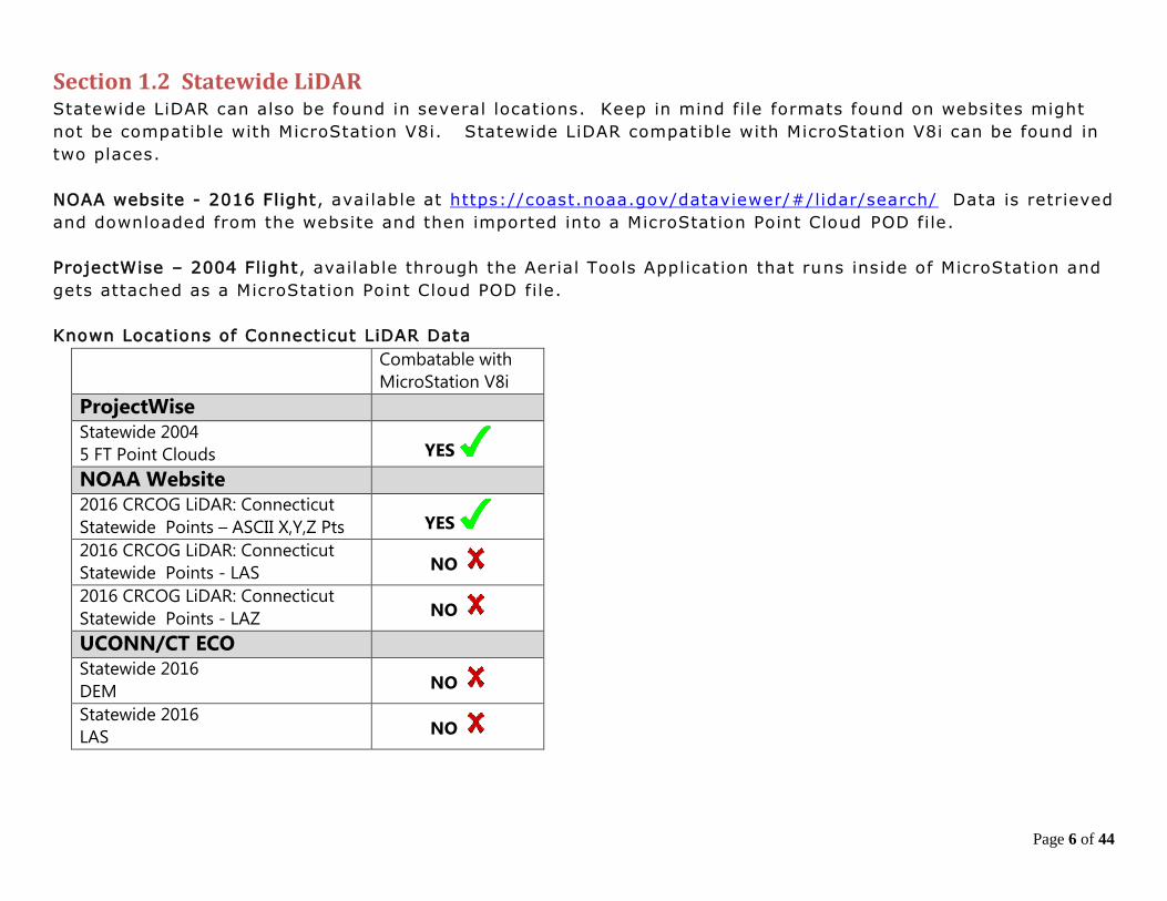
Section 1.2 Statewide LiDAR Statewide LiDAR can also be found in several locations. Keep in mind file formats found on websites might
not be compatible with MicroStation V8i. Statewide LiDAR compatible with MicroStation V8i can be found in
two places.
NOAA website - 2016 Flight, available at https://coast.noaa.gov/dataviewer/#/lidar/search/ Data is retrieved
and downloaded from the website and then imported into a MicroStation Point Cloud POD file.
ProjectWise – 2004 Flight, available through the Aerial Tools Application that runs inside of MicroStation and
gets attached as a MicroStation Point Cloud POD file.
Known Locations of Connecticut LiDAR Data
Combatable with
MicroStation V8i
ProjectWise
Statewide 2004
5 FT Point Clouds YES
NOAA Website
2016 CRCOG LiDAR: Connecticut
Statewide Points – ASCII X,Y,Z Pts YES
2016 CRCOG LiDAR: Connecticut
Statewide Points - LAS NO
2016 CRCOG LiDAR: Connecticut
Statewide Points - LAZ NO
UCONN/CT ECO
Statewide 2016
DEM NO
Statewide 2016
LAS NO
Page 7 of 44
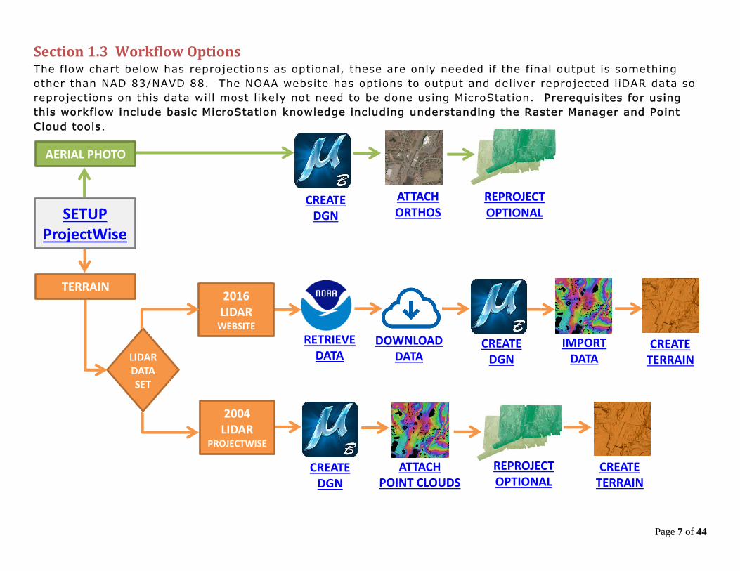
Section 1.3 Workflow Options The flow chart below has reprojections as optional, these are only needed if the final output is something
other than NAD 83/NAVD 88. The NOAA website has options to output and deliver reprojected liDAR data so
reprojections on this data will most likely not need to be done using MicroStation. Prerequisites for using
this workflow include basic MicroStation knowledge including understanding the Raster Manager and Point
Cloud tools.
CREATE DGN
CREATE DGN
CREATE DGN
ATTACH ORTHOS
REPROJECT
OPTIONAL
RETRIEVE DATA
DOWNLOAD
DATA
IMPORT DATA
CREATE TERRAIN
CREATE TERRAIN
ATTACH POINT CLOUDS
REPROJECT
OPTIONAL
LIDAR DATA SET
2016 LIDAR
WEBSITE
2004
LIDAR
PROJECTWISE
TERRAIN
SETUP
ProjectWise
AERIAL PHOTO
Page 8 of 44
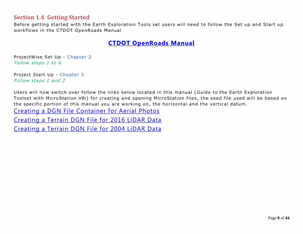
Section 1.4 Getting Started Before getting started with the Earth Exploration Tools set users will need to follow the Set up and Start up
workflows in the CTDOT OpenRoads Manual
CTDOT OpenRoads Manual
ProjectWise Set Up - Chapter 2
Follow steps 1 to 6
Project Start Up - Chapter 3
Follow steps 1 and 2
Users will now switch over follow the links below located in this manual (Guide to the Earth Exploration
Toolset with MicroStation V8i) for creating and opening MicroStation files, the seed file used will be based on
the specific portion of this manual you are working on, the horizontal and the vertical datum.
Creating a DGN File Container for Aerial Photos
Creating a Terrain DGN File for 2016 LiDAR Data
Creating a Terrain DGN File for 2004 LiDAR Data
Page 9 of 44
Section 2.1 Creating a DGN File Container for Aerial Photos 1. In ProjectWise Explorer browse to your working location. On the ProjectWise Explorer Main Menu,
select Document > New Document.
2. In the Select a Wizard Dialog Box, select Advanced Wizard then OK. On the Advanced Document
Creation Wizard Welcome dialog box select Next >. When prompted to Select Target Folder, verify
that you are pointed to the correct folder and select Next >.
3. From the Select a Template options, toggle on Use ProjectWise as a template and click the Select
button.
4. A Select Template Document dialog box will appear. Browse to the seed file location:
5. 0 5. 0 - Workspace Resources\3_Workspace_V8i \Civil_Standards\seed\
6. Choose the 2D seed file 2D_OpenRoads_DesignSeed_83.dgn
7. Select the Open button.
8. The template is now populated for Advanced Document Creation. Select Next >.
9. Select the fields to Define Document Attributes. Tab to accept each field. The document file name will
be built from these fields. Be sure to enter a Label and Description. These fields will be displayed and
used for searching rather than the file name. Select Next >.
10. On the Document Properties Dialog Box select Next >. On the Create a Document Dialog box select
Next >.
11. Click Finish to close. The new file wil l now appear in ProjectWise. To update the ProjectWise Explorer
Document View data point in the view and then select F5 on the keyboard. This wil l refresh Label and
Description.
12. Right click on the DGN file and select Open With. In the Open document with dialog box locate the
Description column and select OpenRoads SS4 and click OK.
Aerial Photos Chapter 2
Page 10 of 44
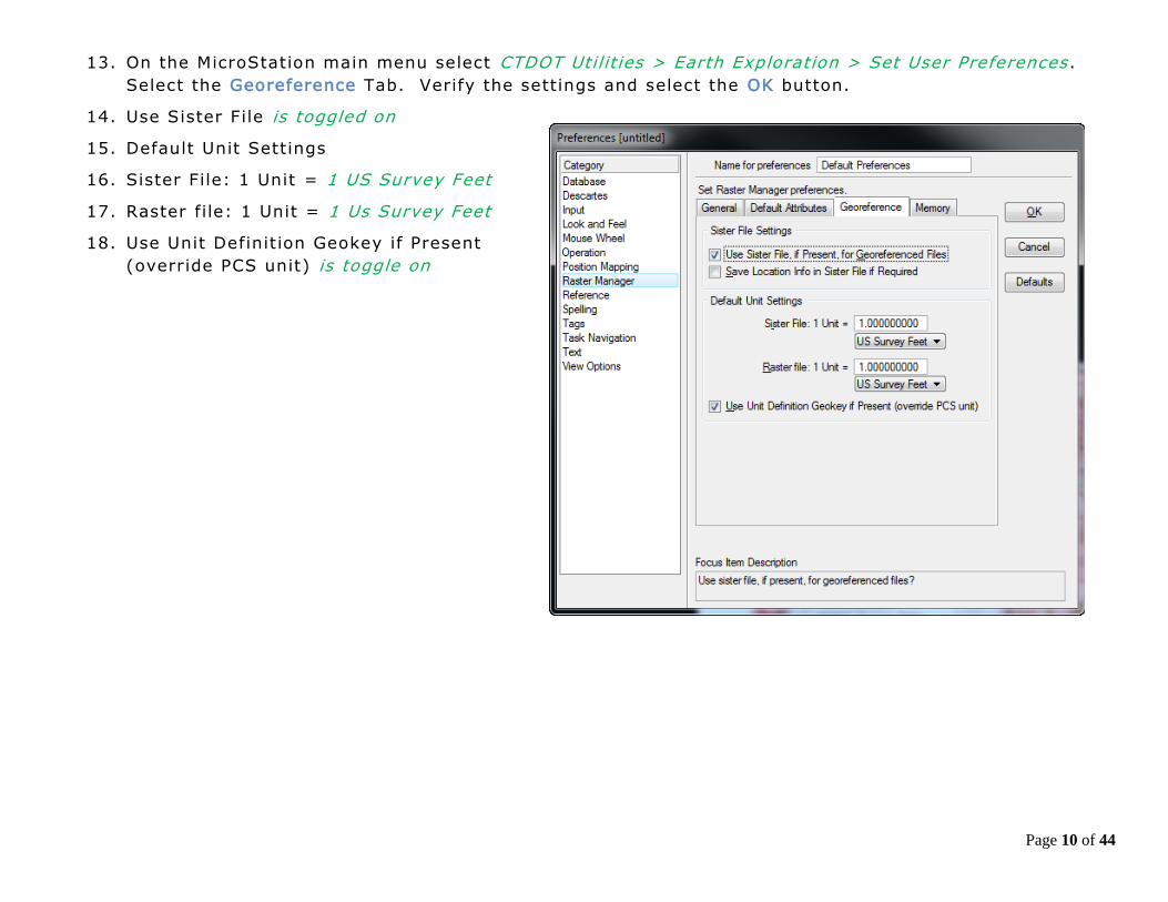
13. On the MicroStation main menu select CTDOT Utilit ies > Earth Exploration > Set User Preferences .
Select the Georeference Tab. Verify the settings and select the OK button.
14. Use Sister File is toggled on
15. Default Unit Settings
16. Sister File: 1 Unit = 1 US Survey Feet
17. Raster file: 1 Unit = 1 Us Survey Feet
18. Use Unit Definition Geokey if Present
(override PCS unit) is toggle on
Page 11 of 44
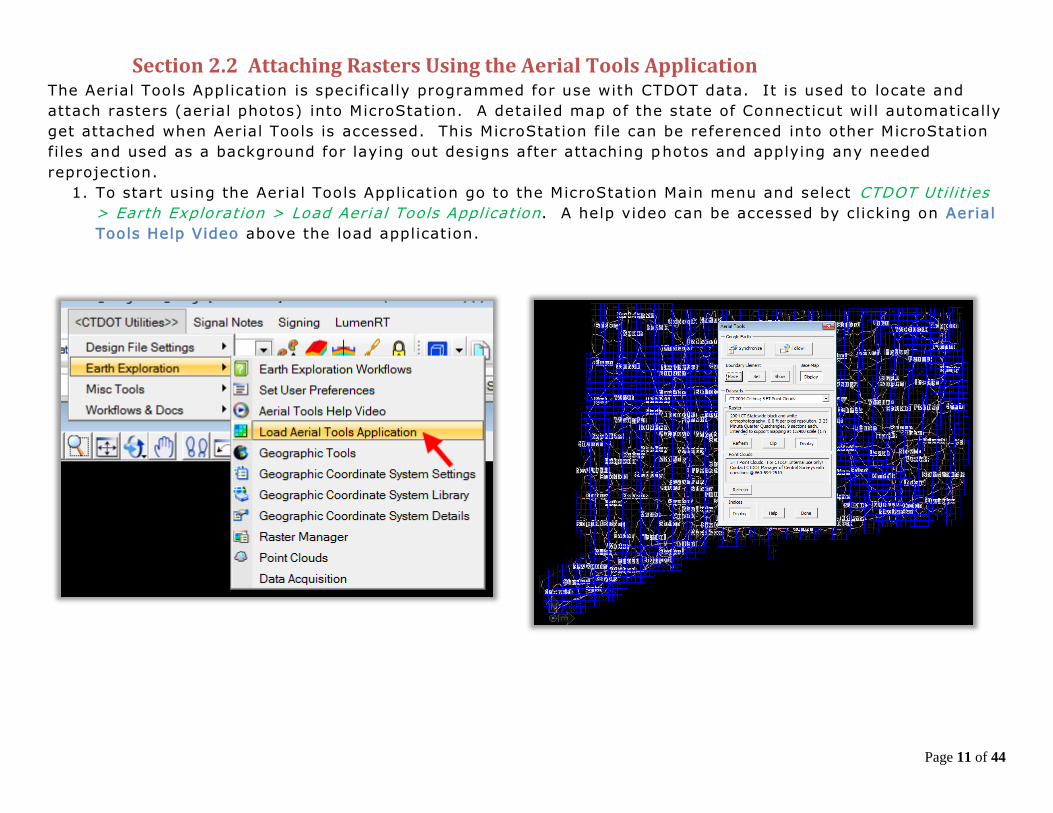
Section 2.2 Attaching Rasters Using the Aerial Tools Application The Aerial Tools Application is specifically programmed for use with CTDOT data. It is used to locate and
attach rasters (aerial photos) into MicroStation. A detailed map of the state of Connecticut wil l automatically
get attached when Aerial Tools is accessed. This MicroStation file can be referenced into other MicroStation
files and used as a background for laying out designs after attaching photos and applying any needed
reprojection.
1. To start using the Aerial Tools Application go to the MicroStation Main menu and select CTDOT Utilit ies
> Earth Exploration > Load Aerial Tools Application. A help video can be accessed by clicking on Aerial
Tools Help Video above the load application.

Page 12 of 44
2. On the Aerial Tools dialog box select the desired data set from the
picklist.
3. In the MicroStation view zoom to the area of interest.
4. On the Aerial Tools Dialog box c lick the Place button and the
MicroStation Place Shape command will load. Place a shape around
the area you would like data to appear. Using MicroStation Element
Section add the shape to your selection set.
5. On the Aerial Tools Dialog box click the Set button. If prompted
with the Boundary Element Box select Yes.
6. On the Aerial Tools Dialog box click the Refresh button in Raster
area. It may take a few minutes to update if you are loading
several files at once.
7. Click Done on the Aerial Tools Dialog Box and the application will
close. The photos will be displayed in the view and be listed in the
Raster Manager dialog box.
Page 13 of 44
Section 2.3 Reprojecting Photos At this point you must have the needed aerial photos attached. You are currently working in the NAD 83
coordinate system and will follow this workflow if you need to rep roject these files to a different system.
Most needed reprojections will be English NAD 83 to English NAD 27 and in some cases metric reprojections
are needed.
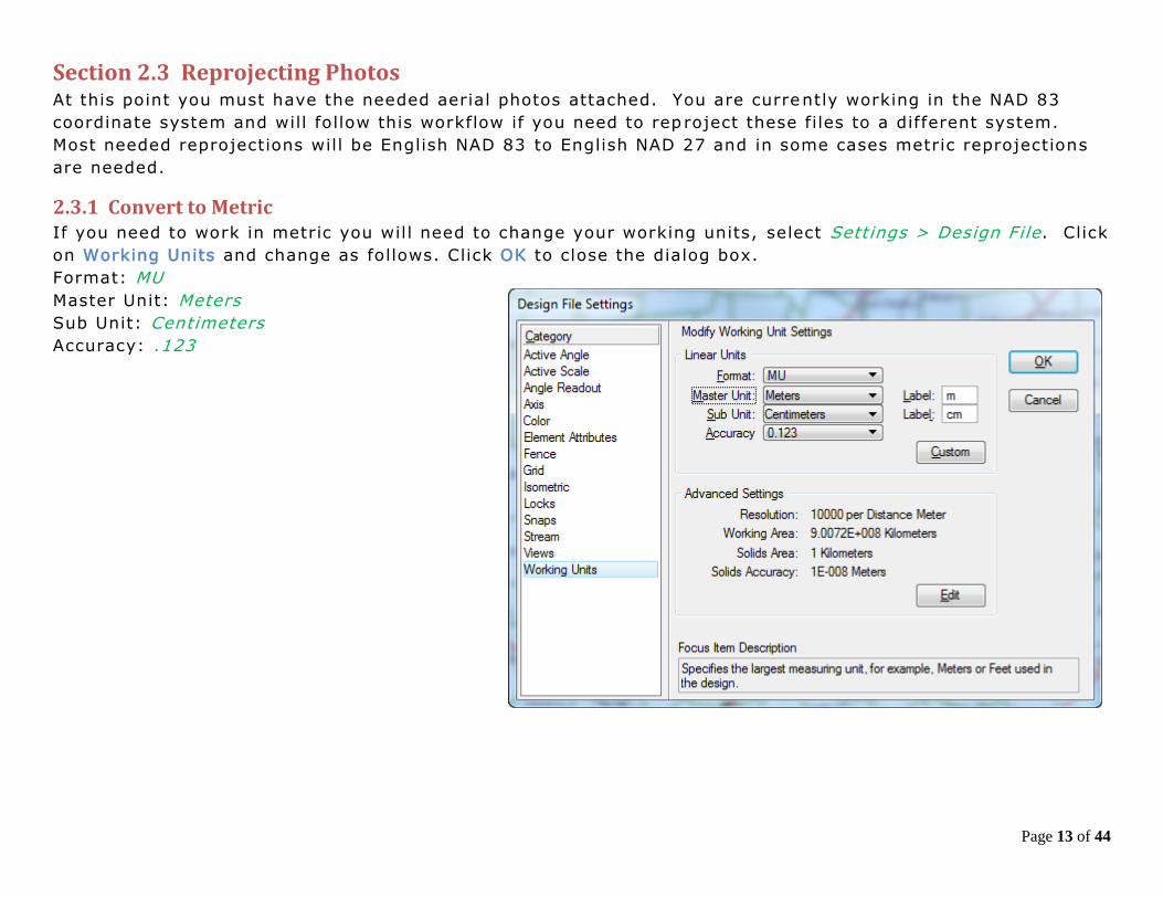
2.3.1 Convert to Metric If you need to work in metric you will need to change your working units, select Settings > Design File. Click
on Working Units and change as follows. Click OK to close the dialog box.
Format: MU
Master Unit: Meters
Sub Unit: Centimeters
Accuracy: .123
Page 14 of 44
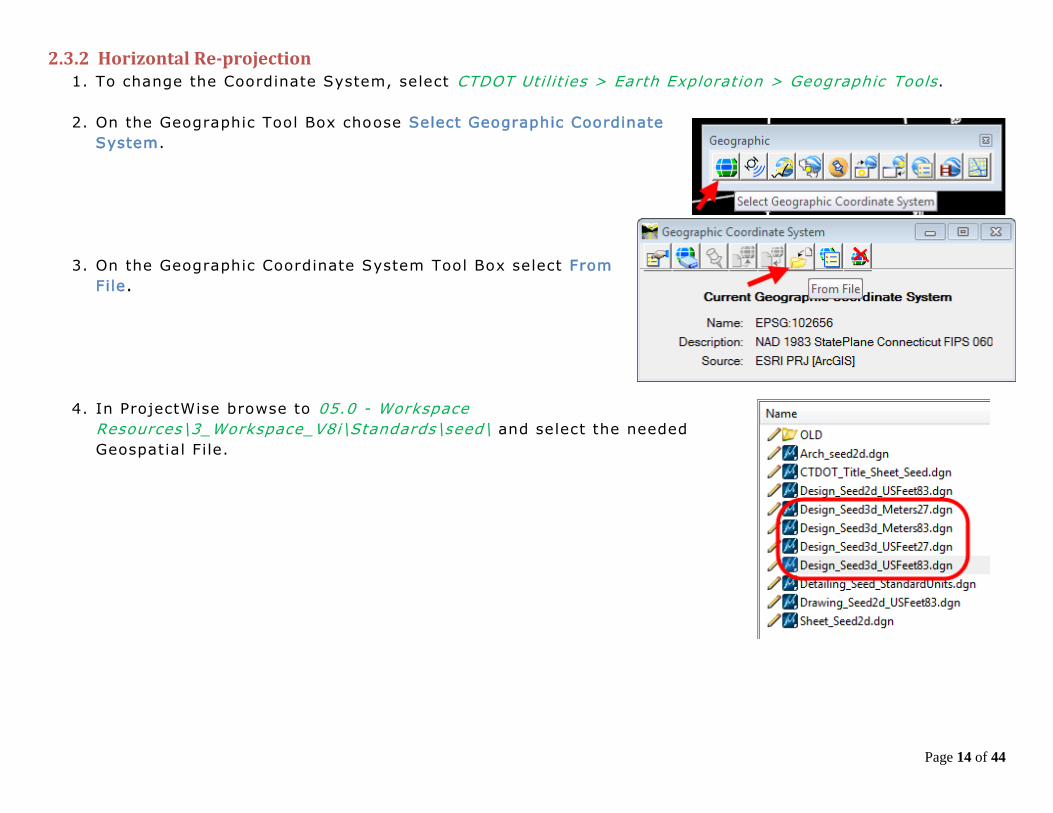
2.3.2 Horizontal Re-projection 1. To change the Coordinate System, select CTDOT Util it ies > Earth Exploration > Geographic Tools.
2. On the Geographic Tool Box choose Select Geographic Coordinate
System.
3. On the Geographic Coordinate System Tool Box select From
File.
4. In ProjectWise browse to 05.0 - Workspace
Resources\3_Workspace_V8i\Standards\seed\ and select the needed
Geospatial File.

Page 15 of 44
5. On the Geographic Coordinate System Changed dialog box
select Reproject the Data to the new Geographic Coordinate
System and select OK.
6. Update the name of your model in the Models
Dialog box to match the reprojection.
7. If you need to use Aerial tools again you will
need to repeat steps 1 to 4 and set the
coordinate system back to English NAD 83.
Page 16 of 44
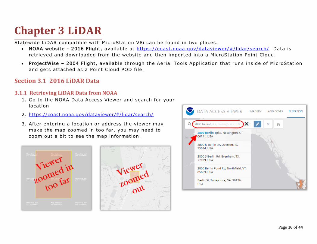
Statewide LiDAR compatible with MicroStation V8i can be found in two places.
NOAA website - 2016 Flight, available at https://coast.noaa.gov/dataviewer/#/lidar/search/ Data is
retrieved and downloaded from the website and then imported into a MicroStation Point Cloud.
ProjectWise – 2004 Flight, available through the Aerial Tools Application that runs inside of MicroStation
and gets attached as a Point Cloud POD file.
Section 3.1 2016 LiDAR Data
3.1.1 Retrieving LiDAR Data from NOAA 1. Go to the NOAA Data Access Viewer and search for your
location.
2. https://coast.noaa.gov/dataviewer/#/lidar/search/
3. After entering a location or address the viewer may
make the map zoomed in too far, you may need to
zoom out a bit to see the map information.
LiDAR Chapter 3
Page 17 of 44
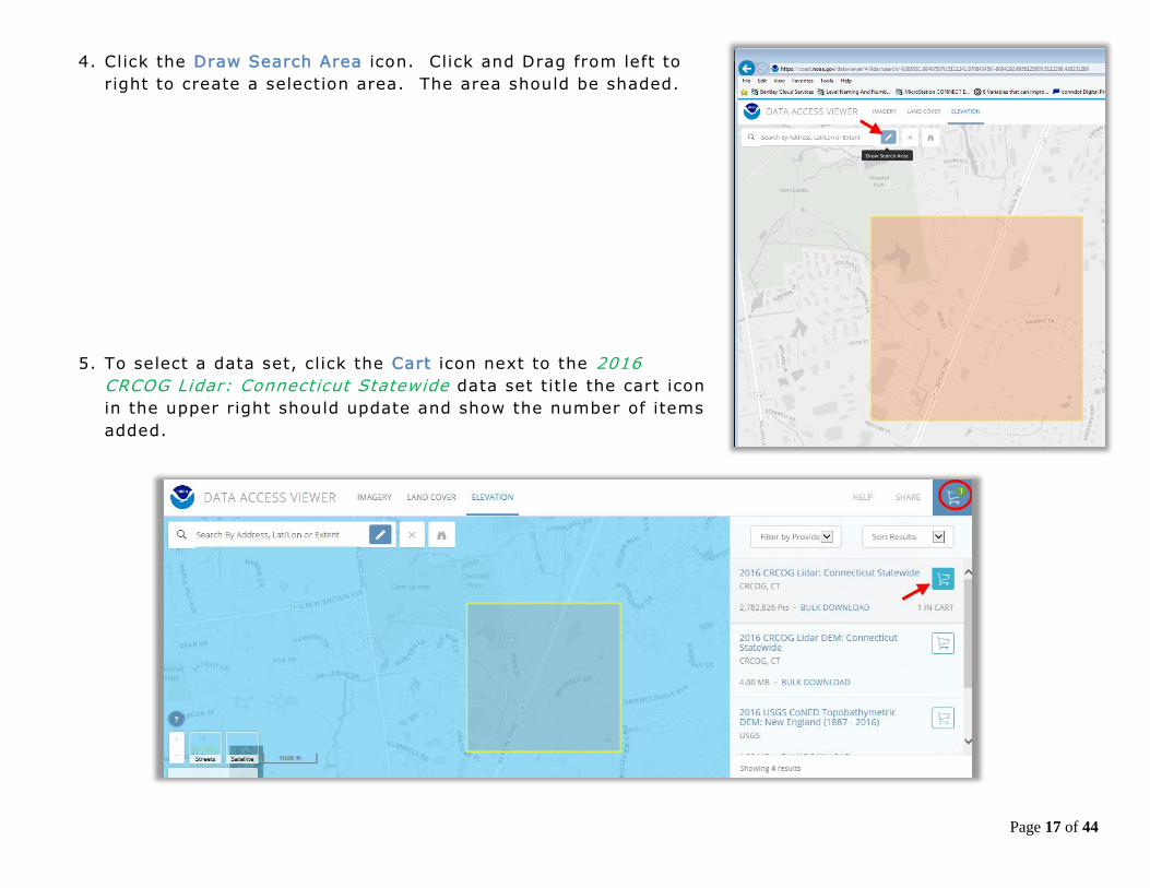
4. Click the Draw Search Area icon. Click and Drag from left to
right to create a selection area. The area should be shaded.
5. To select a data set, click the Cart icon next to the 2016
CRCOG Lidar: Connecticut Statewide data set title the cart icon
in the upper right should update and show the number of items
added.
Page 18 of 44
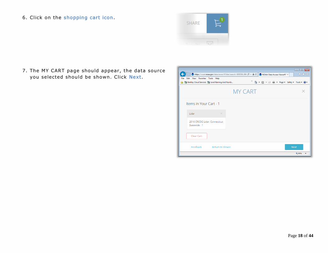
6. Click on the shopping cart icon.
7. The MY CART page should appear, the data source
you selected should be shown. Click Next.
Page 19 of 44
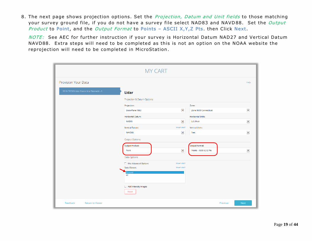
8. The next page shows projection options. Set the Projection, Datum and Unit fields to those matching
your survey ground file, if you do not have a survey file select NAD83 and NAVD88. Set the Output
Product to Point, and the Output Format to Points – ASCII X,Y,Z Pts. then Click Next.
NOTE: See AEC for further instruction if your survey is Horizontal Datum NAD27 and Vertical Datum
NAVD88. Extra steps will need to be completed as this is not an option on the NOAA website the
reprojection will need to be completed in MicroStation .

Page 20 of 44
9. On the next page enter your state email address. Click Next.
10. Review your selections and if correct, click Submit.
11. Take note of the order number provided on the confirmation page and make a note for the location,
this wil l make it easier to sort out emails received later with the data links.

Page 21 of 44
3.1.2 Downloading and Saving the LiDAR Data Set 1. The first email you receive from Digital Coast is a confirmation of the data request. No action needs to
be taken with this email. The second email contains the download link for the data. Click the link in the
email and save the zip file to your project. The third email you receive also contains links to the same
data in the second email. This email can be ignored. Emails may take a few minutes to receive; your
wait time will be longer for larger data sets.

Page 22 of 44
2. After clicking the link, Select Save as. Browse to my documents on your D drive. Create a folder called
NOAA and click Save.
3. In window explorer select the zip file, right click and choose Extract All. The files will extract into a
folder and contain a .txt file(s) and an .xml file.

Page 23 of 44
3.1.3 Creating a Terrain DGN File for 2016 LiDAR Data 1. In ProjectWise Explorer browse to your working location. On the ProjectWise Explorer Main Menu,
select Document > New Document.
2. In the Select a Wizard Dialog Box, select Advanced Wizard then OK. On the Advanced Document
Creation Wizard Welcome dialog box select Next >. When prompted to Select Target Folder, verify that
you are pointed to the correct folder and select Next >.
3. From the Select a Template options, toggle on Use ProjectWise as a template and click the Select
button.
4. A Select Template Document dialog box wil l appear. Browse to the seed file location:
5. 0 5. 0 - Workspace Resources\3_Workspace_V8i \Civil_Standards\seed\
6. Choose the correct 3D seed file 3D_OpenRoads_DesignSeed_83.dgn or
3D_OpenRoads_DesignSeed_27.dgn
7. Select the Open button. The template is now populated for Advanced Document Creation. Select Next >.
8. Select the fields to Define Document Attributes. Tab to accept each field. The document file name will
be built from these fields. Be sure to enter a Label and Description. These fields will be displayed and
used for searching rather than the file name. Select Next >.
9. On the Document Properties Dialog Box select Next >. On the Create a Document Dialog box select
Next >.
10. Click Finish to close. The new file wil l now appear in ProjectWise. To update the ProjectWise Explorer
Document View data point in the view and then select F5 on the keyboard. This wil l refresh Label and
Description.
11. Right click on the DGN file and select Open With. In the Open document with dialog box locate the
Description column and select OpenRoads SS4 and click OK.
Page 24 of 44
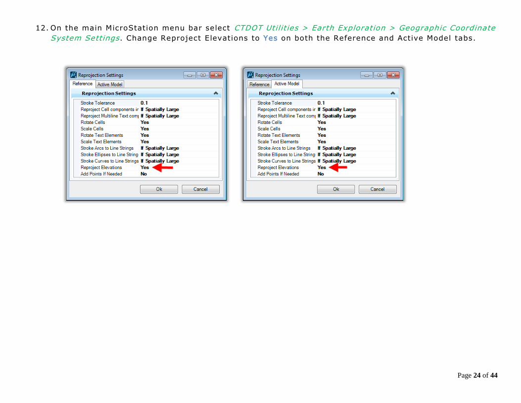
12. On the main MicroStation menu bar select CTDOT Util it ies > Earth Exploration > Geographic Coordinate
System Settings. Change Reproject Elevations to Yes on both the Reference and Active Model tabs.

Page 25 of 44
13. If you downloaded a 1983 State Plane data set with NAD83 horizontal information and chose a vertical
datum of NGVD29 (rather than the typical NAVD88) you will need to adjust the Vertical Datum setting
in MicroStation before importing the points . Select CTDOT Util it ies > Earth Exploration > Geographic
Coordinate System Details . Change the Vertical Datum to National Geodetic Vertical Datum of 1929
and select OK.
14. On the Geographic Coordinate System Changed dialog box select Reproject the Data to the new
Geographic Coordinate System and select OK.
15. On the MicroStation main menu select File > Save Settings.

Page 26 of 44
3.1.4 Creating Point Clouds from LiDAR Data 1. In the MicroStation window click the Point Clouds Icon.
2. The Point Clouds dialog will appear, Click the Attach button.
3. A ProjectWise dialog box will appear, click Cancel and
a Windows Explorer dialog box will appear, browse to
and select the text file that was downloaded from the
NOAA site. Change the Files of Type: to ASCII Files
(*.txt) and click Open.

Page 27 of 44
4. A dialog for converting ASCII will open, make sure the columns
are set to x, y, z and the Geometry Units are set to Feet if the
job is in English and Meters if the job is in Metric. Click OK.
5. The Select a Wizard dialog box will appear, select No Wizard
and click OK.
6. The Specify new pod file dialog box will appear, Save the file as
a .pod file ensuring it will go into the correct folder in
ProjectWise. It may take some time, wait until cursor comes
back.
7. Click Fit View to see the points.
8. To make the points easier to see, go to the View Attributes
dropdown and set the Point Cloud Presentation Style to
Elevation. To change the display click on the Magnifying Icon
under Point Cloud Presentation. Select the desired look under
Depth and Colorization and click Save Settings. For more
information about Point Clouds go to Section 4 - Working with
Point Clouds. You can also set this from the Point Clouds
dialog, choose Settings>Presentation and select Elevation. Right
click to apply to open views.

Page 28 of 44
3.1.5 Creating a Terrain from Point Clouds 1. On the MicroStation Task menu select Civil Tools >
Terrain Model and select the Create from Point
Cloud Icon.
2. On the Create Terrain From Point Cloud dialog box
select the following:
3. Filter: None
4. Feature Definition: EX_TERR_Triangles
5. Edge Method: No Removal
6. Click on the Import Button and triangles will appear
on your screen.
7. You should now detach the POD file so only the
Terrain is in the files.
8. Hoover over the triangles and set the Terrain
active. The Terrain is now part of the MicroStation
DGN. This file can be referenced in and used as the
existing terrain for an OpenRoads preliminary
design work.
NOTE: If the file spins out and you experience a
crash the file you are trying to create maybe
too big. Go to Section 5.1 for directions on
how to reduce the size of the import.

Page 29 of 44
Section 3.2 2004 LiDAR Data
3.2.1 Creating a Terrain DGN File for 2004 LiDAR Data 1. In ProjectWise Explorer browse to your working location. On the ProjectWise Explorer Main Menu,
select Document > New Document.
2. In the Select a Wizard Dialog Box, select Advanced Wizard then OK. On the Advanced Document
Creation Wizard Welcome dialog box select Next >. When prompted to Select Target Folder, verify
that you are pointed to the correct folder and select Next >.
3. From the Select a Template options, toggle on Use ProjectWise as a template and click the Select
button.
4. A Select Template Document dialog box will appear. Browse to the seed file location:
0 5. 0 - Workspace Resources\3_Workspace_V8i \Civil_Standards\seed\
5. Choose the correct 3D seed file 3D_OpenRoads_DesignSeed_83.dgn
6. Select the Open button. The template is now populated for Advanced Document Creat ion. Select Next
>.
7. Select the fields to Define Document Attributes. Tab to accept each field. The document file name will
be built from these fields. Be sure to enter a Label and Description. These fields will be displayed and
used for searching rather than the file name. Select Next >.
8. On the Document Properties Dialog Box select Next >. On the Create a Document Dialog box select
Next >.
9. Click Finish to close. The new file wil l now appear in ProjectWise. To update the ProjectWise Explorer
Document View data point in the view and then select F5 on the keyboard. This wil l refresh Label and
Description.

Page 30 of 44
10. Right click on the DGN file and select Open With. In the Open document with dialog box locate the
Description column and select OpenRoads SS4 and click OK.
11. On the main MicroStation menu bar select CTDOT Util it ies > Earth Exploration > Geographic Coordinate System Settings. Change Reproject Elevations to Yes on both tabs.

Page 31 of 44
3.2.2 Attaching POD Files using The Aerial Tools Application 1. To start using the Aerial Tools Application go to the MicroStation Main menu and select CTDOT Utilit ies
> Earth Exploration > Load Aerial Tools Application. A help video can be accessed by clicking on Aerial
Tools Help Video above the load application.

Page 32 of 44
2. On the Aerial Tools Dialog box select CT 2004 Orthos, 5FT Point Clouds
from the Picklist.
3. In the MicroStation view zoom to the area of interest.
4. On the Aerial Tools Dialog box c lick the Place button and the MicroStation
Place Shape command will load. Place a shape around the area you would
like data to appear. Using MicroStation Element Section add the shape to
your selection set.
5. On the Aerial Tools Dialog box click the Set button. If prompted with the
Boundary Element Box select Yes.
6. On the Aerial Tools Dialog box click the Refresh button in Point Clouds
area. It may take a few minutes to update if you are loading several files
at once. Click Cancel on the Attach Point Cloud Reference File dialog box,
this box may pop up several times just continue to hit cancel until it no
longer comes up.
7. Click Done on the Aerial Tools Dialog Box and the application will close.
8. To make the points easier to see, go to the View Attributes dropdown and
set the Point Cloud Presentation Style to Elevation. To change the display
click on the Magnifying Icon under Point Cloud Presentation. Select the
desired look under Depth and Colorization and click Save Settings. For more
information about Point Clouds go to Section 4 - Working with Point Clouds.
You can also set this from the Point Clouds dialog, choose
Settings>Presentation and select Elevation. Right click to apply to open
views.
Page 33 of 44
3.2.3 Re-Projecting Data At this point you must have the needed point clouds attached. You are currently working in the NA D 83
coordinate system and will follow this part of the workflow only if you need to repoject these files to a
different system. Most needed reprojections will be English NAD 83 – NAVD 88 to English NAD 27 to NAVD
29. But in some cases the English NAD 83 – NAVD 29, English NAD 27 – NAVD 88 and metric reprojections
may be needed.
3.2.3.1 Convert to Metric
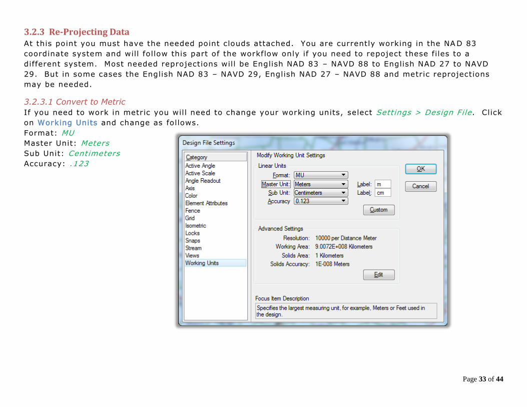
If you need to work in metric you will need to change your working units, select Settings > Design File. Click
on Working Units and change as follows.
Format: MU
Master Unit: Meters
Sub Unit: Centimeters
Accuracy: .123
Page 34 of 44
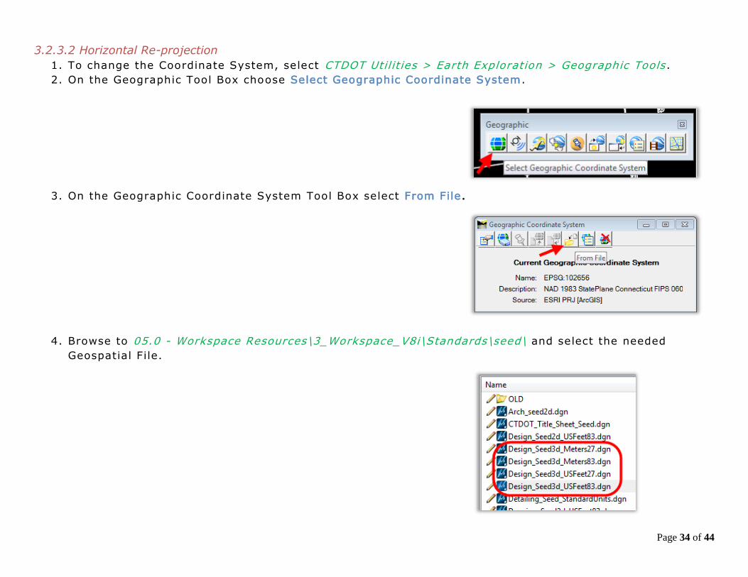
3.2.3.2 Horizontal Re-projection
1. To change the Coordinate System, select CTDOT Util it ies > Earth Exploration > Geographic Tools .
2. On the Geographic Tool Box choose Select Geographic Coordinate System.
3. On the Geographic Coordinate System Tool Box select From File.
4. Browse to 05.0 - Workspace Resources\3_Workspace_V8i\Standards\seed\ and select the needed
Geospatial File.
Page 35 of 44
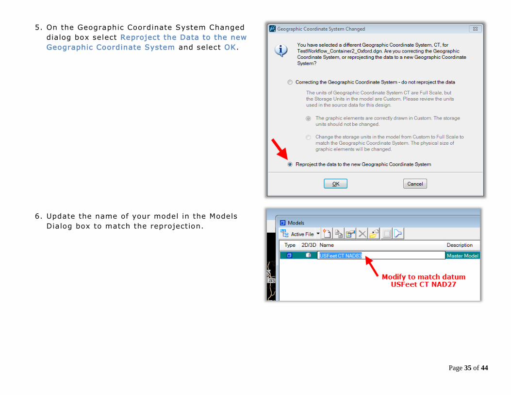
5. On the Geographic Coordinate System Changed
dialog box select Reproject the Data to the new
Geographic Coordinate System and select OK.
6. Update the name of your model in the Models
Dialog box to match the reprojection.
Page 36 of 44
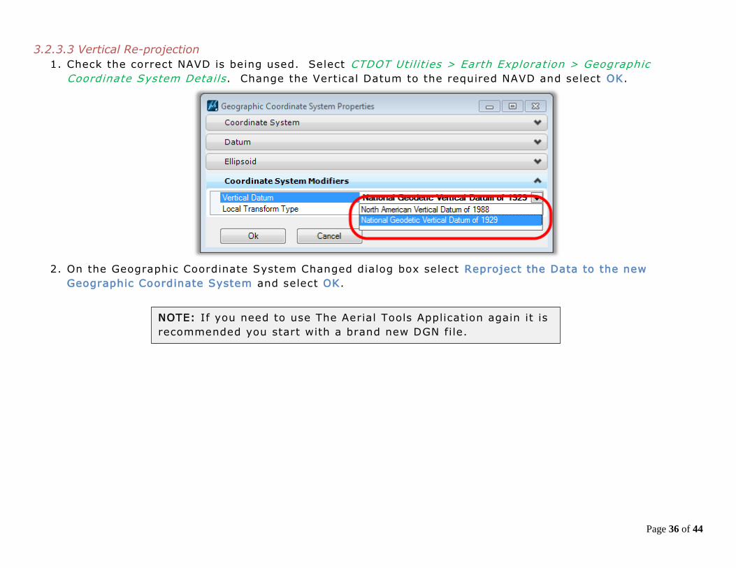
3.2.3.3 Vertical Re-projection
1. Check the correct NAVD is being used. Select CTDOT Utilit ies > Earth Exploration > Geographic
Coordinate System Details . Change the Vertical Datum to the required NAVD and select OK.
2. On the Geographic Coordinate System Changed dialog box select Reproject the Data to the new
Geographic Coordinate System and select OK.
NOTE: If you need to use The Aerial Tools Application again it is
recommended you start with a brand new DGN file.

Page 37 of 44
3.2.4 Creating a Terrain from Point Clouds
1. On the MicroStation Task menu select Civil Tools > Terrain
Model and select the Create from Point Cloud Icon.
2. On the Create Terrain From Point Cloud dialog box select the
following:
Filter: None
Feature Definition: EX_TERR_Triangles
Edge Method: No Removal
3. Click on the Import Button and triangles will appear
on your screen.
4. You should now detach the POD file so only the
Terrain is in the files.
5. Hoover over the triangles and set the Terrain active.
The Terrain is now part of the MicroStation DGN. This
file can be referenced in and used as the existing
terrain for an OpenRoads preliminary design work.
NOTE: If the file spins out and you experience a
crash the file you are trying to create maybe
too big. Go to Section 5.1 for directions on
how to reduce the size of the import.

Page 38 of 44
A point cloud is a data file which can include a large number of points on the surface of an object. A point
cloud is a set of vertices in a 3D coordinate system and these vertices are defined the by X, Y and Z
coordinates. Point clouds are usually created by 3D scanners. These devices measure a large number of
points on the surface of an object and output a point cloud as a data file. The point cloud represents the
visible surface of the object that has been scanned or digitized. Point clouds are used for many purposes,
especially to confirm measurements between the DGN model and the real world.
Working with Point Clouds Chapter 4
Page 39 of 44
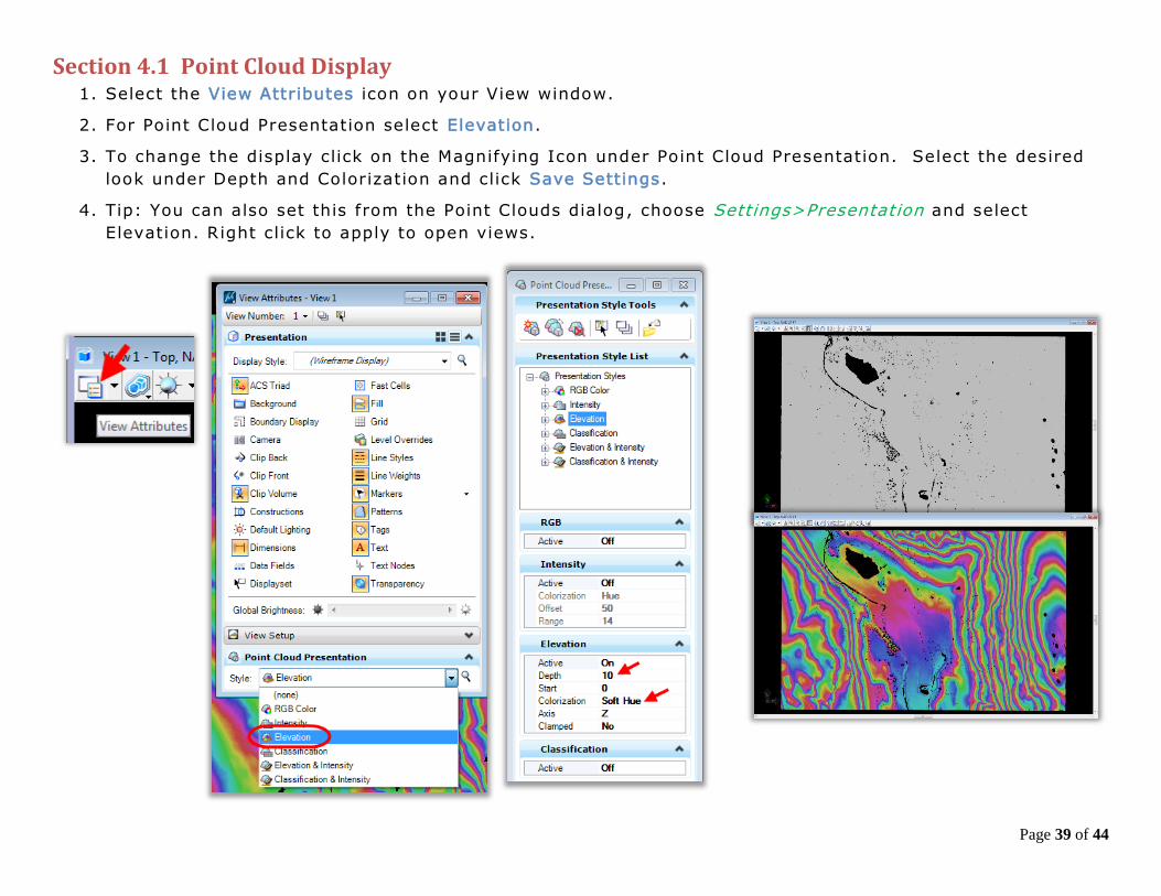
Section 4.1 Point Cloud Display 1. Select the View Attributes icon on your View window.
2. For Point Cloud Presentation select Elevation.
3. To change the display click on the Magnifying Icon under Point Cloud Presentation. Select the desired
look under Depth and Colorization and click Save Settings.
4. Tip: You can also set this from the Point Clouds dialog, choose Settings>Presentation and select
Elevation. Right click to apply to open views.
Page 40 of 44
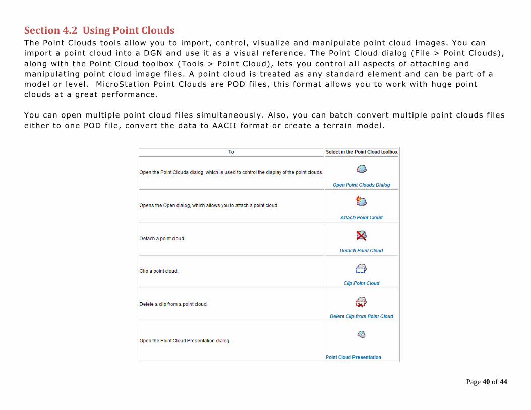
Section 4.2 Using Point Clouds The Point Clouds tools allow you to import, control, visualize and manipulate point cloud images. You can
import a point cloud into a DGN and use it as a visual reference. The Point Cloud dialog (File > Point Clouds),
along with the Point Cloud toolbox (Tools > Point Cloud), lets you cont rol all aspects of attaching and
manipulating point cloud image files. A point cloud is treated as any standard element and can be part of a
model or level. MicroStation Point Clouds are POD files, this format allows you to work with huge point
clouds at a great performance.
You can open multiple point cloud files simultaneously. Also, you can batch convert multiple point clouds files
either to one POD file, convert the data to AACII format or create a terrain model.

Page 41 of 44
Section 4.3 Modifying a Point Cloud A point Cloud and be clipped and the density of the points can be
filtered down. This may need to be done on extremely large data
sets so when the terrain gets created you will have manageable
size data. OpenRoads Terrains and be much larger than the
traditional InRoads DTMs. OpenRoads Terrain uses a scalable
technology allowing for much larger files. There is a limit, please
do not try to get a surface from point clouds for the entire state
of Connecticut, your computer and the software will surely lock
up.
1. Select Edit > Clip in the Point Clouds dialog box, in the Clip
Point Cloud Dialog box select the placement method.
2. Highlight all the point clouds and select File > Export. In
the Export Point Cloud box set the following:
Format = Pointools POD (*.pod)
Region Filter = Clip
Density = set as desired
Click OK.
3. Select No Wizard and OK, when the next box appears select your
project folder and rename the clipped POD file. C lick Save.
Page 42 of 44
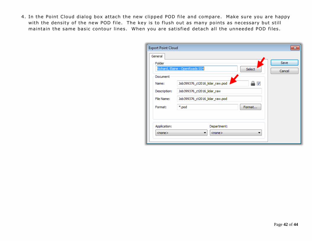
4. In the Point Cloud dialog box attach the new clipped POD file and compare. Make sure you are happy
with the density of the new POD file. The key is to flush out as many points as necessary but still
maintain the same basic contour lines. When you are satisfied detach all the unneeded POD files.
Page 43 of 44
The Tile Filter uses an algorithm that divides the LIDAR data set into tiles. A best fit plane is calculated for
each tile, and LIDAR points are removed if they fall within the user set Z tolerance to the plane.
The TIN Filter first separates the LIDAR points into tiles with a maximum of 2 million points and then
repetitively triangulates each tile, filtering out points. The TIN Filter algorithm filters out the points if they
fall within the user set Z tolerance of the triangle planes.
No Filter – No filtering is applied
Z Tolerance - common to both algorithms and is basically the variation in the Z coordinate that the surface is
allowed to move during the filtering process. Typically for the first invocation of the filtering function, the Z
tolerance should be set from 0.5 to 1.0 for imperial data sets and from 0.25 to 0.5 for metric data sets.
Depending on the outcome and the desired result, the Z tolerance can be varied up or down.
Max. Tile Points - specifies that a tile will not be subdivided if it has less than this number of points.
Typically this is set to five.
Max. Tile Divisions - the allowable level of recursion allowed and is the number of time the initial til ing set
can be subdivided. Typically this is set to five.
Start Tile Length – The LIDAR data set is initially divided into tiles of this size, prior to recursion to the
minimum tile points. The setting of this parameter requires some knowledge of the distance between the
LIDAR points, which requires an inspection of the LIDAR points in MicroStation to determine. Typically set
this to 10 times the distance between the LIDAR points.
Course Filter (TIN option only) – Filter more points with some blurring of ridges and valleys
Fine Filter (TIN option only) – Filters fewer points with less blurring of ridges and valleys Points
Before Filter/Points After Filter/Reduction % - Display of the number of points before and after filtering, plus
the percentage reduction of points from before and after
Filter Descriptions Chapter 5

Page 44 of 44
Section 5.1 Bentley Recommendations for Creating a Large Terrain from a Point Cloud Always use the “Tin Filter”.
Input the “Z” Tolerance.
Always use the “Coarse” option.
Always use “Reinsert Points” option.
Do not specify a feature definition; change it after
the import is complete.