Glass Installation Guide
32
Americas 2021 English Español Français Canadien Glass Installation Guide Guidelines for installing your new Glass board Doc # 100204 | Rev B | Page 1 of 32
Transcript of Glass Installation Guide

Americas 2021
EnglishEspañolFrançais Canadien
Glass Installation Guide
Guidelines for installing your new Glass board
Doc # 100204 | Rev B | Page 1 of 32

3 Safety Requirements
4 Handling + Storing of Panels
5 Required Materials + Equipment
6 Installation
11 Warranty
English
Doc # 100204 | Rev B | Page 2 of 32

Glass - Wall Mounted Frameless Dry Erase Board, Non-Seismic Applications
Safety Requirements
Minimum Required Wall Construction
Drywall with metal studs:
• Must be at least 25 ga. (0.018” or .5 mm thick) 33 ksi steel studs 38 mm x 89 mm (1.5” x 3.5”)
• Studs on maximum 610 mm (24”) centers
• Must be at least 16 mm (5/8”) thick Type X gypsum drywall for the US or 12 mm (1/2”) for EU
• 32 mm (#6 x 1-1/4”) drywall screws on 305 mm (12”) centers
Verify Wall Construction
CAUTION! Adequate wall construction is required to support the weight of the board. Minimum wall construction must be capable of supporting weight amounts listed in Table 1 on page 6.
Drywall with wooden studs:
• Stud grade SPF, DF-L or Hem-Fir 38 mm x 89 mm (1.5” x 3.5”)
• Studs on 610 mm (24”) centers
• Must be at least 16 mm (5/8”) thick Type X gypsum drywall for the US or 12 mm (1/2”) for EU
• 32 mm (#6 x 1-1/4”) drywall screws on 305 mm (12”) centers
The building’s Engineer of Record must be consulted to determine if there are any seismic requirements.
Doc # 100204 | Rev B | Page 3 of 32

Handling + Storing of Panels
Handling
• When Glass panels are shipped, they are protected by craft paper or a self-adhesive transparent polyethylene film. Keep panels in the original package until installation.
• Handle with care to prevent damage.
• Never slide panels off the stack during handling. Panels should always be lifted and moved in a vertical position.
• Never place an Glass panel in a vertical position on the floor. This is to prevent damage to the edges.
• Prevent dirt from settling on and between panels to avoid surface damage, scratches or defects.
• Follow all safety instructions regarding personal protection when processing the panels.
• Protect panel surface against sawdust and sparks (metal particles).
• Glass will chip when cut or drilled with power tools. Hand-cutting can cause chipping up to approx. 2 mm from the edge. When chipping is in excess of 2 mm, please check the state of cutting tools and check that the panel is adequately supported and clamped to prevent it from vibrating.
• All cut or drilled sections should be protected against humidity with PVC tape and/or by covering/sealing profiles or sealing washers.
• For detailed processing instructions, please refer to the Glass processing instructions.
Storing
• Keep panels dry and free of debris.
• Store panels inside temps 50-90 °F (10-32 °C).
• Any panels stored outside should be protected from inclement weather conditions.
• Place panels on hard, flat surfaces that are not subject to standing water.
• Glass panels should be stacked no more than three high.
• Panels should never be stored vertically or in such a way that the corners are vulnerable to damage.
If you have a problem, question, or a request, call your local fabricator, your regional sales manager or PolyVision Customer Service. PolyVision’s global customer service team can be contacted on polyvision.com.
Doc # 100204 | Rev B | Page 4 of 32

Required Materials + Equipment
Required Equipment
Materials Provided
NOTE: Items are not drawn to size. Quantity of brackets will vary per product due to the various widths. Drywall screws and anchors are not provided.
Refer to Table 1 for screw and anchor quantities required by size.
Brackets*Glass panel(s)
* Table 1
Product Size Orientation Brackets Anchors /Screws
48” x 48” - 2 10
48” x 72”Horizontal 2 14
Vertical 4 20
48” x 96”Horizontal 2 22
Vertical 4 20
· Drill
· #2 Bit
· Glass suction cup lifters (2)
· Pliers
· Pencil
· Level
· 2 or 3-step ladder
· Tape measure
· 1-1/4” drywall screws
· Wall anchors
Before starting the installation of Glass
1. Verify that the required equipment is available and material provided is accurate.
2. Provide adequate protection for finished floor surfaces.
3. All Glass installations should be carried out by two or more individuals.
Doc # 100204 | Rev B | Page 5 of 32

Installation
Step One
· Use appropriate mounting specification based on the size and the orientation of your Glass board
NOTE: You may drill holes in the support bracket to install into the wall stud for strongest support.Anchor into wall studs as often as possible. Mounting heights are recommendations only.
Recommended Mounting Heights
A = 77”
B = 34-1/4”
Product # of Studs Weight (kg)
48” x 48” 2 56 lbs
48” x 72” 3 96 lbs
48” x 96” 4 128 lbs
Horizontal Orientation
Vertical Orientation
Recommended Mounting Heights
C = 69-11/16”
D = 19-3/8”
Product # of Studs Weight (kg)
48” x 72” 2 96 lbs
48” x 96” 2 128 lbs
Recommended Mounting Heights
C =92-29/32”
D = 27-3/8”
48” x 72” 48” x 96”
Doc # 100204 | Rev B | Page 6 of 32

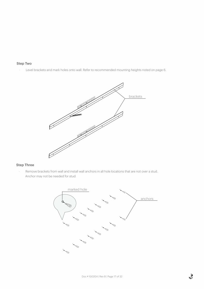
Step Two
· Level brackets and mark holes onto wall. Refer to recommended mounting heights noted on page 6.
Step Three
· Remove brackets from wall and install wall anchors in all hole locations that are not over a stud.Anchor may not be needed for stud.
brackets
marked hole
anchors
Doc # 100204 | Rev B | Page 7 of 32

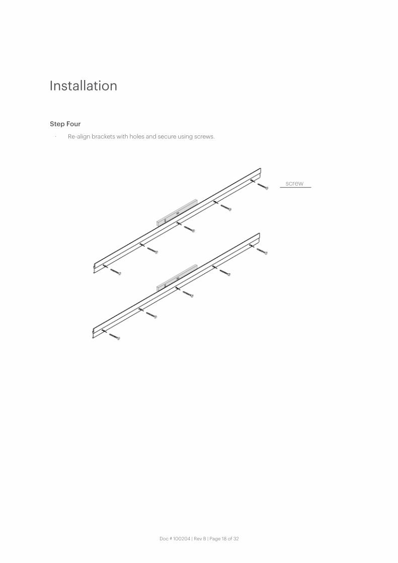
Step Four
· Re-align brackets with holes and secure using screws.
screw
Installation
Doc # 100204 | Rev B | Page 8 of 32

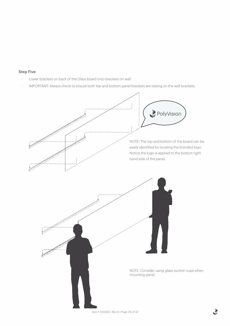
Step Five
· Lower brackets on back of the Glass board onto brackets on wall.
· IMPORTANT: Always check to ensure both top and bottom panel brackets are resting on the wall brackets.
NOTE: Consider using glass suction cups when mounting panel.
NOTE: The top and bottom of the board can be
easily identified by locating the branded logo.
Notice the logo is applied to the bottom right
hand side of the panel.
Doc # 100204 | Rev B | Page 9 of 32

Step Six
· Installation of PolyVision Glass is complete.
Installation
Doc # 100204 | Rev B | Page 10 of 32

Doc # 100204 | Rev B | Page 11 of 32

3 Safety Requirements
4 Handling + Storing of Panels
5 Required Materials + Equipment
6 Installation
11 Warranty
Español
Doc # 100204 | Rev B | Page 12 of 32

Glass - Wall Mounted Frameless Dry Erase Board, Non-Seismic Applications
Safety Requirements
Minimum Required Wall Construction
Drywall with metal studs:
• Must be at least 25 ga. (0.018” or .5 mm thick) 33 ksi steel studs 38 mm x 89 mm (1.5” x 3.5”)
• Studs on maximum 610 mm (24”) centers
• Must be at least 16 mm (5/8”) thick Type X gypsum drywall for the US or 12 mm (1/2”) for EU
• 32 mm (#6 x 1-1/4”) drywall screws on 305 mm (12”) centers
Verify Wall Construction
CAUTION! Adequate wall construction is required to support the weight of the board. Minimum wall construction must be capable of supporting weight amounts listed in Table 1 on page 6.
Drywall with wooden studs:
• Stud grade SPF, DF-L or Hem-Fir 38 mm x 89 mm (1.5” x 3.5”)
• Studs on 610 mm (24”) centers
• Must be at least 16 mm (5/8”) thick Type X gypsum drywall for the US or 12 mm (1/2”) for EU
• 32 mm (#6 x 1-1/4”) drywall screws on 305 mm (12”) centers
The building’s Engineer of Record must be consulted to determine if there are any seismic requirements.
Doc # 100204 | Rev B | Page 13 of 32

Handling + Storing of Panels
Handling
• When Glass panels are shipped, they are protected by craft paper or a self-adhesive transparent polyethylene film. Keep panels in the original package until installation.
• Handle with care to prevent damage.
• Never slide panels off the stack during handling. Panels should always be lifted and moved in a vertical position.
• Never place an Glass panel in a vertical position on the floor. This is to prevent damage to the edges.
• Prevent dirt from settling on and between panels to avoid surface damage, scratches or defects.
• Follow all safety instructions regarding personal protection when processing the panels.
• Protect panel surface against sawdust and sparks (metal particles).
• Glass will chip when cut or drilled with power tools. Hand-cutting can cause chipping up to approx. 2 mm from the edge. When chipping is in excess of 2 mm, please check the state of cutting tools and check that the panel is adequately supported and clamped to prevent it from vibrating.
• All cut or drilled sections should be protected against humidity with PVC tape and/or by covering/sealing profiles or sealing washers.
• For detailed processing instructions, please refer to the Glass processing instructions.
Storing
• Keep panels dry and free of debris.
• Store panels inside temps 50-90 °F (10-32 °C).
• Any panels stored outside should be protected from inclement weather conditions.
• Place panels on hard, flat surfaces that are not subject to standing water.
• Glass panels should be stacked no more than three high.
• Panels should never be stored vertically or in such a way that the corners are vulnerable to damage.
If you have a problem, question, or a request, call your local fabricator, your regional sales manager or PolyVision Customer Service. PolyVision’s global customer service team can be contacted on polyvision.com.
Doc # 100204 | Rev B | Page 14 of 32

Required Materials + Equipment
Required Equipment
Materials Provided
NOTE: Items are not drawn to size. Quantity of brackets will vary per product due to the various widths. Drywall screws and anchors are not provided.
Refer to Table 1 for screw and anchor quantities required by size.
Brackets*Glass panel(s)
* Table 1
Product Size Orientation Brackets Anchors /Screws
48” x 48” - 2 10
48” x 72”Horizontal 2 14
Vertical 4 20
48” x 96”Horizontal 2 22
Vertical 4 20
· Drill
· #2 Bit
· Glass suction cup lifters (2)
· Pliers
· Pencil
· Level
· 2 or 3-step ladder
· Tape measure
· 1-1/4” drywall screws
· Wall anchors
Before starting the installation of Glass
1. Verify that the required equipment is available and material provided is accurate.
2. Provide adequate protection for finished floor surfaces.
3. All Glass installations should be carried out by two or more individuals.
Doc # 100204 | Rev B | Page 15 of 32

Installation
Step One
· Use appropriate mounting specification based on the size and the orientation of your Glass board
NOTE: You may drill holes in the support bracket to install into the wall stud for strongest support.Anchor into wall studs as often as possible. Mounting heights are recommendations only.
Recommended Mounting Heights
A = 77”
B = 34-1/4”
Product # of Studs Weight (kg)
48” x 48” 2 56 lbs
48” x 72” 3 96 lbs
48” x 96” 4 128 lbs
Horizontal Orientation
Vertical Orientation
Recommended Mounting Heights
C = 69-11/16”
D = 19-3/8”
Product # of Studs Weight (kg)
48” x 72” 2 96 lbs
48” x 96” 2 128 lbs
Recommended Mounting Heights
C =92-29/32”
D = 27-3/8”
48” x 72” 48” x 96”
Doc # 100204 | Rev B | Page 16 of 32
Step Two
· Level brackets and mark holes onto wall. Refer to recommended mounting heights noted on page 6.
Step Three
· Remove brackets from wall and install wall anchors in all hole locations that are not over a stud.Anchor may not be needed for stud.
brackets
marked hole
anchors
Doc # 100204 | Rev B | Page 17 of 32
Step Four
· Re-align brackets with holes and secure using screws.
screw
Installation
Doc # 100204 | Rev B | Page 18 of 32

Step Five
· Lower brackets on back of the Glass board onto brackets on wall.
· IMPORTANT: Always check to ensure both top and bottom panel brackets are resting on the wall brackets.
NOTE: Consider using glass suction cups when mounting panel.
NOTE: The top and bottom of the board can be
easily identified by locating the branded logo.
Notice the logo is applied to the bottom right
hand side of the panel.
Doc # 100204 | Rev B | Page 19 of 32

Step Six
· Installation of PolyVision Glass is complete.
Installation
Doc # 100204 | Rev B | Page 20 of 32

Doc # 100204 | Rev B | Page 21 of 32

3 Safety Requirements
4 Handling + Storing of Panels
5 Required Materials + Equipment
6 Installation
11 Warranty
Français Canadien
Doc # 100204 | Rev B | Page 22 of 32

Glass - Wall Mounted Frameless Dry Erase Board, Non-Seismic Applications
Safety Requirements
Minimum Required Wall Construction
Drywall with metal studs:
• Must be at least 25 ga. (0.018” or .5 mm thick) 33 ksi steel studs 38 mm x 89 mm (1.5” x 3.5”)
• Studs on maximum 610 mm (24”) centers
• Must be at least 16 mm (5/8”) thick Type X gypsum drywall for the US or 12 mm (1/2”) for EU
• 32 mm (#6 x 1-1/4”) drywall screws on 305 mm (12”) centers
Verify Wall Construction
CAUTION! Adequate wall construction is required to support the weight of the board. Minimum wall construction must be capable of supporting weight amounts listed in Table 1 on page 6.
Drywall with wooden studs:
• Stud grade SPF, DF-L or Hem-Fir 38 mm x 89 mm (1.5” x 3.5”)
• Studs on 610 mm (24”) centers
• Must be at least 16 mm (5/8”) thick Type X gypsum drywall for the US or 12 mm (1/2”) for EU
• 32 mm (#6 x 1-1/4”) drywall screws on 305 mm (12”) centers
The building’s Engineer of Record must be consulted to determine if there are any seismic requirements.
Doc # 100204 | Rev B | Page 23 of 32

Handling + Storing of Panels
Handling
• When Glass panels are shipped, they are protected by craft paper or a self-adhesive transparent polyethylene film. Keep panels in the original package until installation.
• Handle with care to prevent damage.
• Never slide panels off the stack during handling. Panels should always be lifted and moved in a vertical position.
• Never place an Glass panel in a vertical position on the floor. This is to prevent damage to the edges.
• Prevent dirt from settling on and between panels to avoid surface damage, scratches or defects.
• Follow all safety instructions regarding personal protection when processing the panels.
• Protect panel surface against sawdust and sparks (metal particles).
• Glass will chip when cut or drilled with power tools. Hand-cutting can cause chipping up to approx. 2 mm from the edge. When chipping is in excess of 2 mm, please check the state of cutting tools and check that the panel is adequately supported and clamped to prevent it from vibrating.
• All cut or drilled sections should be protected against humidity with PVC tape and/or by covering/sealing profiles or sealing washers.
• For detailed processing instructions, please refer to the Glass processing instructions.
Storing
• Keep panels dry and free of debris.
• Store panels inside temps 50-90 °F (10-32 °C).
• Any panels stored outside should be protected from inclement weather conditions.
• Place panels on hard, flat surfaces that are not subject to standing water.
• Glass panels should be stacked no more than three high.
• Panels should never be stored vertically or in such a way that the corners are vulnerable to damage.
If you have a problem, question, or a request, call your local fabricator, your regional sales manager or PolyVision Customer Service. PolyVision’s global customer service team can be contacted on polyvision.com.
Doc # 100204 | Rev B | Page 24 of 32

Required Materials + Equipment
Required Equipment
Materials Provided
NOTE: Items are not drawn to size. Quantity of brackets will vary per product due to the various widths. Drywall screws and anchors are not provided.
Refer to Table 1 for screw and anchor quantities required by size.
Brackets*Glass panel(s)
* Table 1
Product Size Orientation Brackets Anchors /Screws
48” x 48” - 2 10
48” x 72”Horizontal 2 14
Vertical 4 20
48” x 96”Horizontal 2 22
Vertical 4 20
· Drill
· #2 Bit
· Glass suction cup lifters (2)
· Pliers
· Pencil
· Level
· 2 or 3-step ladder
· Tape measure
· 1-1/4” drywall screws
· Wall anchors
Before starting the installation of Glass
1. Verify that the required equipment is available and material provided is accurate.
2. Provide adequate protection for finished floor surfaces.
3. All Glass installations should be carried out by two or more individuals.
Doc # 100204 | Rev B | Page 25 of 32

Installation
Step One
· Use appropriate mounting specification based on the size and the orientation of your Glass board
NOTE: You may drill holes in the support bracket to install into the wall stud for strongest support.Anchor into wall studs as often as possible. Mounting heights are recommendations only.
Recommended Mounting Heights
A = 77”
B = 34-1/4”
Product # of Studs Weight (kg)
48” x 48” 2 56 lbs
48” x 72” 3 96 lbs
48” x 96” 4 128 lbs
Horizontal Orientation
Vertical Orientation
Recommended Mounting Heights
C = 69-11/16”
D = 19-3/8”
Product # of Studs Weight (kg)
48” x 72” 2 96 lbs
48” x 96” 2 128 lbs
Recommended Mounting Heights
C =92-29/32”
D = 27-3/8”
48” x 72” 48” x 96”
Doc # 100204 | Rev B | Page 26 of 32

Step Two
· Level brackets and mark holes onto wall. Refer to recommended mounting heights noted on page 6.
Step Three
· Remove brackets from wall and install wall anchors in all hole locations that are not over a stud.Anchor may not be needed for stud.
brackets
marked hole
anchors
Doc # 100204 | Rev B | Page 27 of 32

Step Four
· Re-align brackets with holes and secure using screws.
screw
Installation
Doc # 100204 | Rev B | Page 28 of 32
Step Five
· Lower brackets on back of the Glass board onto brackets on wall.
· IMPORTANT: Always check to ensure both top and bottom panel brackets are resting on the wall brackets.
NOTE: Consider using glass suction cups when mounting panel.
NOTE: The top and bottom of the board can be
easily identified by locating the branded logo.
Notice the logo is applied to the bottom right
hand side of the panel.
Doc # 100204 | Rev B | Page 29 of 32

Step Six
· Installation of PolyVision Glass is complete.
Installation
Doc # 100204 | Rev B | Page 30 of 32

Doc # 100204 | Rev B | Page 31 of 32

©2021 PolyVision Corporation. All rights reserved. Trademarks used herein are the property of PolyVision Corporation or of their respective owner. PolyVision Corporation reserves the right to make changes in product design, construction or detail, and to discontinue any product or material without notice.
polyvision.com 04-22-2021 EMEA
PolyVision Americas10700 Abbotts Bridge Road Suite 100 Johns Creek, GA 30097 USA
T 1 888 325 6351E [email protected]
PolyVision EuropeZuiderring 56 3600 Genk, Belgium
T +32 89 32 31 30E [email protected]
PolyVision Asia-Pacific15th Floor, Kinwick Centre 32 Hollywood Road, Central District Hong Kong
T +852 2520 0160E [email protected]