KIMAX - smillieltd.casmillieltd.ca/pdfDocs/Kimax-Schott-Glass/Installation-Guide-Glass...kimax ® is...
12
Glass Drainline Installation Guide KIMAX ®
Transcript of KIMAX - smillieltd.casmillieltd.ca/pdfDocs/Kimax-Schott-Glass/Installation-Guide-Glass...kimax ® is...

Glass Drainline Installation Guide
KIMAX®

2
Complete System, Reliable, Easy to Install
EASY TO INSTALLWith few exceptions, KIMAX® glass drainline
installs in much the same manner as you
would install any drainline system.
KIMAX pipe and fittings possess good
mechanical strength, so you don’t need to
handle the system with kid gloves.
There is no limit to the length or height to
which KIMAX glass drainline can be installed.
It can be enclosed within a wall, if permitted
by code. It can be buried in the ground,
underneath concrete, or inside a trough or
sleeve.
For above ground installation, drainline pipe
is available in 5’ and 10’ lengths in diameters
from 1.5” through 6”. For underground use,
5’ lengths come protected with an expanded
polystyrene casing. The system also includes a
complete line of glass fittings and traps, plus
the accessories and hardware to meet
virtually any laboratory drain and vent
system requirements.
KIMAX drainline weighs less than conventional
drainline materials, so it’s easy to handle,
fewer hangers and joints are required and
sections can be preassembled and carried to
the point of installation. Expansion is
negligible, therefore expansion joints are not
needed or recommended.
SIMPLE, LEAK-PROOF JOINTSConventional glass-to-glass connections are made
quickly and simply using #6650 KIMAX couplings.
Just as easily, you can join 1.5", 3", 4" and 6" glass
(beaded end) drainline to plain end glass, metal or
rigid plastic pipe using #6661 KIMAX B/P (Bead to
Plain End) couplings. See opposite page for details.
When properly installed both couplings will provide
leak-free joints – even with line deflections of up to
four degrees.
With B/P couplings and the KIMAX portable glass
cutter, you can cut and join 1.5" through 6" glass
drainline anywhere on the jobsite.
TTeefflloonn® iiss aa rreeggiisstteerreedd ttrraaddeemmaarrkk ooff DDuuPPoonntt.. KKiimmaaxx® iiss aa rreeggiisstteerreedd ttrraaddeemmaarrkk ooff KKiimmbbllee GGllaassss IInncc..
3
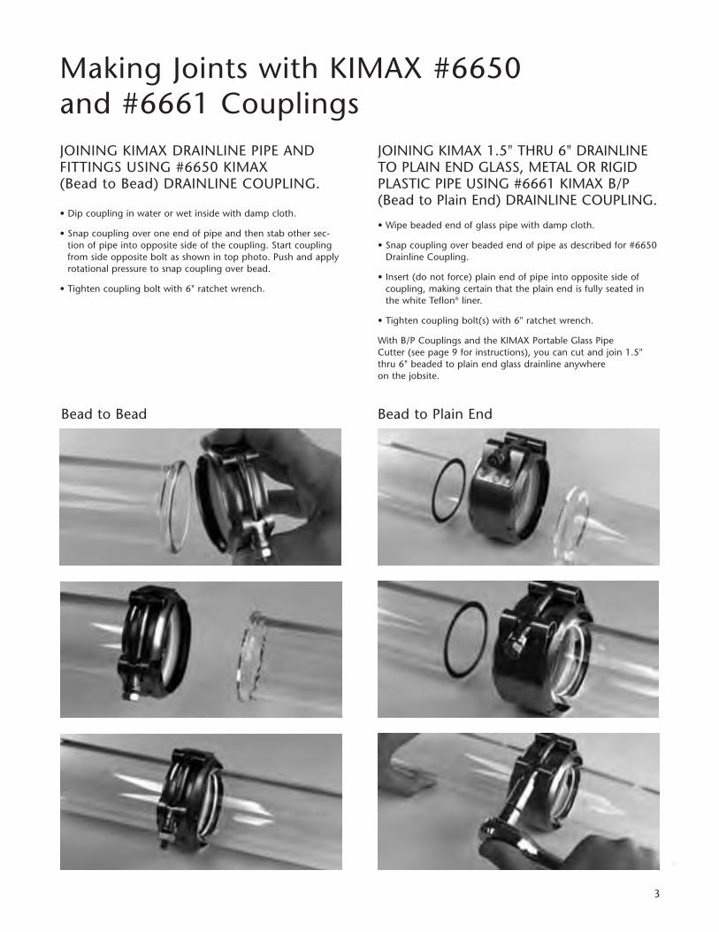
Making Joints with KIMAX #6650 and #6661 CouplingsJOINING KIMAX DRAINLINE PIPE AND FITTINGS USING #6650 KIMAX (Bead to Bead) DRAINLINE COUPLING.
• Dip coupling in water or wet inside with damp cloth.
• Snap coupling over one end of pipe and then stab other sec-tion of pipe into opposite side of the coupling. Start couplingfrom side opposite bolt as shown in top photo. Push and applyrotational pressure to snap coupling over bead.
• Tighten coupling bolt with 6" ratchet wrench.
JOINING KIMAX 1.5" THRU 6" DRAINLINETO PLAIN END GLASS, METAL OR RIGIDPLASTIC PIPE USING #6661 KIMAX B/P(Bead to Plain End) DRAINLINE COUPLING.
• Wipe beaded end of glass pipe with damp cloth.
• Snap coupling over beaded end of pipe as described for #6650Drainline Coupling.
• Insert (do not force) plain end of pipe into opposite side ofcoupling, making certain that the plain end is fully seated inthe white Teflon® liner.
• Tighten coupling bolt(s) with 6" ratchet wrench.
With B/P Couplings and the KIMAX Portable Glass Pipe Cutter (see page 9 for instructions), you can cut and join 1.5"thru 6" beaded to plain end glass drainline anywhere on the jobsite.
Bead to Bead Bead to Plain End

4
Typical Joint Reference Chart
G A S K E T
S i z e O u t l e t
1½"
2½"
2"
2"
3½" x 5⁄ 1 6"
4 1 ⁄ 1 6" x 5 ⁄ 1 6"
H o l e C o u n t e r b o re
L O C K N U T
K I M A X 6 6 6 1 B / PC O U P L I N G ,1 ½ " , 2"
K I M A X 6 7 2 0 - 1 5 0 0S I N K O U T L E T
K I M A X 6 7 2 0 - 1 5 0 0S I N K O U T L E TA S S E M B LY, 1 ½ "
K I M A X 6 7 3 5 - 1 5 0 0S P L I T CO U P L I N G 1 ½ "
K I M A X 6 7 2 8 - 1 5 0 0TA I L P I E C E AS S E M B LY,1 ¼ " I . D . ( 1 ½ " O . D . )x 6 ½ " o r 1 0 ½ " L O N G
1 ½ " B E A D E D P I P EO R T R A P
A S S E M B LY, 1 ½ "
Type of Joint Materials Needed Steps to be Taken
1.5", 2" KIMAX Sink Outlet
ToKIMAX Beaded
Pipe or Trap(same size)
Installing KIMAX Sink Outlet
1.5" KIMAX(or plastic or metal I.P.S.threaded) Sink Outlets
To1.5" KIMAX Beaded
Pipe or Trap
1.5" KIMAX(or plastic or metal I.P.S.threaded) Sink Outlets
to1.5" KIMAX
Tailpiece Assembly
1. Drill hole in sink bottom as indicated for size outlet being installed.
2. Drill counter bore to proper diameterand depth.
3. Smooth bottom of counter bore andinsert gasket.
4. Remove locknut and insert outletthrough sink hole
5. Screw locknut tight against sink bottom
6. Seal gap between outlet lip and counterbore with acid-resistant 3M-EC-612caulking compound or equivalent.
Note: Install stainless steel in same manner as above.
1. Snap coupling over beaded end of pipe or trap.
2. Slide opposite (grooved) side of coupling onto threaded outlet. Do not force but make certain that outletend is fully seated in coupling.
3. Tighten coupling bolt with 6" ratchet wrench.
1. Remove clamp from split coupling.
2. Position coupling halves over glass bead.
3. Replace and tighten clamp.
4. Screw coupling onto threaded outlet.
Note: Use 6739 Gasket when connectingKIMAX beaded pipe or trap to metalthreaded sink outlet.
• Slide plastic nut up to top (beadedend) of tailpiece.
• Screw nut onto threaded outlet.
Note: Use 6738 Gasket when connect-ing glass tailpiece to metal threaded sinkoutlet.

5
Typical Joint Reference Chart
1. Snap coupling over beaded end of trap inlet.
2. Slide coupling up over plain and tailpiece or cup sink to desired height.
3. Tighten coupling bolt with 6 inch ratchet wrench.
Note: Use KIMAX adapter coupling 2" x 1 1/2" to connect to Pyrex sink outlet or plain end cupsink.
K I M A X 6 6 5 5 A D A P T E R C O U P L I N G
O . D .S I Z E
R A N G E
2 " I N L E T O N T R A PO R A D J U S TA B L E F I T T I N G
1 ½ " x 1 ¼ " O . D . # 6 6 6 5 - 1 5 1 21 ½ " x 1 ½ " O . D . # 6 6 6 5 - 1 5 1 5W I T H R U B B E R S E A L O N LY
L E A D A N D O A K U M O R A C I D - R E S I S TA N T C A U L K
3 M - E C - 6 1 2 C A U L K I N G C O M P O U N D W H E R E N O N - H A R D E N I N G J O I N T I S D E S I R E D
1 2 "
K I M A X 6 6 8 0 T H R E A D A D A P T E R
K I M A X 6 6 5 0 C O U P L I N G( S A M E S I Z E A S T H R E A D A D A P T E R )
T H R E A D E D P I P E 1 ½ "
P I P E O R T R A P, 2 "
G A S K E T
F L A N G E
C O N I C A L E N D P I P E
K I M A X 7 1 1 0C O U P L I N GA S S E M B LY( B E A D E D T OC O N I C A LE N D P I P E )
B E A D E D P I P E
F L A N G E
B O LT S
A D A P T E R I N S E RT
I N S E RT
K I M A X 6 6 8 5A D J U S T . T H R E A D A D A P T E R2 " x 1 ½ "
Type of Joint Materials Needed Steps to be Taken
KIMAX BeadedOr Plain End Pipe
To Metal Bell and
Spigot Type
1. For line flexibility, place coupling within12 inches of caulked joint.
2. If using plain-end glass pipt, smoothexternal rough edges with fine carborun-dum stone or 150-grit emery cloth.
3. Insert glass into hub using care so as not toscratch glass. Pack space between glassand hub firmly with non-combustiblepacking material – then back off glass 1/2" to 1/2" from base of hub.
4. If using lead pour in lead* at lowest temperature and caulk lightly with anacid-resistant caulk.
Note: If lead is used, preheat glass firstuntil water drop sizzles.*Pack with lead wool if joining glassto vitreous tile hub.
1. Disassemble coupling and remove inserts
2. Slide proper flange over conical end pipeand snap in flange insert.
3. Slide other flange over beaded end pipeand snap in flange adapter insert.
4. Slide both flanges firmly against pipe ends.
5. Insert gasket between pipe ends.
6. Replace bolts and tighten nuts evenly.
1.5" KIMAX (or otherglass,metal or plastic)Plain End Tailpiece or
Plain End CupsinkTo
2" KIMAX Trap InletOr Adjustable Fitting
Metal or PlasticI.P.S Threaded Pipe(straight or tapered)1.5", 2" 3", 4" or 6"
toKIMAX Beaded Pipe or
Trap (same size)
KIMAX (conical end)Process Pipe,
1.5", 2", 3", 4" or 6"to
KIMAX Beaded Pipeor Trap (same Size)
1. Screw thread adapter onto threaded pipeuntil it “bottoms". With adjustableadapter, screw into threaded pipe untildesired height adjustment is reached.
2. Snap coupling over adapter.
3. Stab beaded pipe or trap into oppositeside of coupling.
4. Tighten coupling bolt with 6 inch ratchetwrench.
Note: Use 6685 Adjust. Adapter to join 11/2" threaded pipe to 2" KIMAX beadedtrap or pipe.
Coupling Size Tailpiece Style O.D Size Range
2 x 1 1/2
2 x 1 3/4
2 x 1 7/8
1.48 to 1.53
1.70 to 1.78
1.82 to 1.90
KIMAX Glass tail pipe ExtensionNo. 6728, metal tubing, andlead tailpiece extensions.
Lead, Class D or XL tailpiecePYREX tailpiece and cup sink
Plain end KIMAX Regular Scheduleor Heavy Schedule1 1/2 glass pipe or fittingsDurcon # SO-2Duriron #11713Lead – Class C or L, B or MPlastic or Steel (11/2 IPS)

6
Hanging KIMAX Drainline–Horizontally
• Use padded hangers (to prevent glass to metal contact) to support lines every 8 feet to10 feet.
• Use extra hanger when three or more couplings fall within 8 foot to 10 foot span.
Note: AAppropriate ppadded hhangers aare available ffrom SSchott NNorth AAmerica IInc.
• Do not pull or spring pipe into place. Movehanger to pipe, not pipe to hanger.
• Completely tighten coupling as each joint ismade.
• Keep lines loose. When horizontal lines arehung they should be free to move sideways.
• Pipe passing through walls should be fittedwith pipe sleeve at least two inches greater indiameter than pipe O.D.
• Pack space between pipe and sleeve withFiberglas or glass wool.
Note: KKIMAX ppipe iis UU.L. CClassified aas aa ffirepenetrant, ffor ppenetrating ffire rrated ffloors.System NNumbers ffor KKIMAX ppipe aare llisted iinthe UU.L. FFire RResistance DDirectory uunder tthefile nnumber RR11306.
• To pitch a line, snug coupling, cock joint asrequired to a maximum 4° deflection.

7
Hanging KIMAX Drainline–Vertically
• Use coated riser clamps.
• Support 1.5" and 2" stacks at every other floor.
• Support 3", 4" and 6" stacks at every floor.
• Where possible riser clamp should be placed underneath a coupling.
• Place riser clamps either above or below floor.
• Clamp should be below bottom coupling in stackand where possible, below coupling on every thirdfloor.
• Do not support vertical stacks with horizontal lines.First hanger should be placed from 6 feet to 8 feetfrom stack.
• Pipe passing through floors or slabs should be fittedwith pipe sleeve at least two inches greater in diam-eter than pipe O.D.
• Pack space between pipe and sleeve with Fiberglasor glass wool.
• Install coupling within 6" of floor or slab to giveflexibility.
Note: KKIMAX ppipe iis UU.L. CClassified aas aa ffire penetrant, ffor ppenetrating ffire rrated ffloors.System NNumbers ffor KKIMAX ppipe aare llisted iin the UU.L. FFire RResistance DDirectory uunder tthe ffilenumber RR11306.

8
S TA I N L E S SS T E E L P I P E
G L A S S D R A I N L I N E
G L A S S D R A I N L I N E
K I M A X 6 6 6 1B / P C O U P L I N G
S TA I N L E S S S T E E L F L O O R D R A I N
A C I D P R O O F C E M E N T
A C I D - R E S I S TA N TC A U L K
S TA I N L E S S S T E E L F L O O R D R A I N
M E T H O D 2
M E T H O D 1
M E T H O D 1
M E T H O D 2
TA P E O R I N S U L AT I O N
TA P E O R I N S U L AT I O N
S E A M L E S SL E A D F L A S H I N G
S E A M L E S SL E A D F L A S H I N G
A C I D - R E S I S TA N T C A U L KC O U N T E R F L A S H I N G S L E E V E
CONNECTING TTO FFLOOR DDRAIN
METHOD 11: Screw I.P.S. threaded metalnipple into outlet of floor drain and jointhe glass pipe or fitting to nipple using aKIMAX 6661 B/P Coupling.
METHOD 22: Cut glass pipe to desiredlength using KIMAX portable cutting tool.Smooth external sharp edges from cut endand insert into outlet of floor drain. Sealglass in place using non-combustible pack-ing material, and acid-proof cement.
Hanging KIMAX Drainline–Vertically
FLASHING TTHROUGH RROOF
When flashing through a roof, wrap the ventpipe with tape or an insulating material andfollow through using either of the methodsindicated below:
METHOD 11: Seamless lead roof flashing with acaulked counter-flashing sleeve.
METHOD 22: Seamless lead or copper roofflashing.
NOTE: The annular opening for the ventshould be 2" greater than the pipe O.D. beingstubbed through the roof.

9
Cutting KIMAX Drainline Pipe
TOOLS NNEEDED• Cutting Tool:
7310-2000, 1.5" – 2" Diameter PipeCutter 7310-2000 is specifically designed and recommended for easier and faster installationof 1.5" and 2" diameter pipe7310-56802, 1.5" and 2", 3"- 4" and 6" Diameter Pipe.
• Safety Glasses• Grease Pencil• Measuring Tape• Propane or Butane Hand Torch• Emery Cloth or Carborundum Stone• Work Bench with Backstop
TO AASSEMBLE CCUTTER TTOOLS1. Slide centering cone and ring stop onto
extension* and tension shafts.2. Firmly couple tension shaft and scoring head assembly.
Use small cutter head, 7310-S-1000 for 1.5" and 2" pipe and large cutter head 7310-F-5000 for 3"-4" and 6" pipe. A cone for cutting 6" pipe must be ordered separately.
*Use extension shaft if cutting pipe over 2 1/2 feet long.
PIPE SSTORAGEProtect pipe from scratches. Leave pipe in shipping cartons untilimmediately prior to installation. Used cartons provide protection to glass pipe on floor prior to cutting or installation.
TO CCUT PPIPEMEASURE AND MARK – Measure length of pipe required and markcutting point with grease pencil, making sure surface of glass is dry.NOTE: DO NOT ATTEMPT TO CUT WITHIN 8" OF A FACTORYBEADED PIPE END.
INSERT CUTTER – Insert scoring head into pipe with red cutterwheel up and cutter arms completely retracted. Do not scratchinside or outside of pipe as this can cause breakage.
SEAT CONE/LOCK RING STOP – Slide centering cone into pipe untilfirmly seated against cut or beaded end. Align cutter wheel withcutting mark. Slide ring stop against centering cone and lock ringstop by tightening thumb screw.NOTE: WORKBENCH MUST HAVE BACKSTOP FOR OPPOSITE ENDOF PIPE.
TENSION TO SCORE – Turn tension adjustment knob clockwise. Re-check alignment of cutter wheel with pencil mark. Continueturning tension adjustment handle clockwise to give cutter wheelsufficient pressure to score glass. A medium to light score is desir-able on all sizes except 6" which requires a heavier score.
SCORE THE PIPE – With the pipe against the backstop, centeringcone pressed firmly into the pipe, and ring stop locked against cen-tering cone, make a test score (about 1/2" long) by turning the ten-sion shaft clockwise. Make final adjustment if necessary. Complete
the score by turning tension shaft one full turn – making sure toclose cutting circle, but not the score beyond the starting point.The tension adjustment handle may require adjustment while scoring to maintain a uniform score as the cutter is turned.
RELEASE TENSION/REMOVE CUTTER – Turn tension adjustmentknob completely counter-clockwise to draw cutter wheel away fromglass. With red cutter head facing up, and cutter arms retracted,withdraw cutter from pipe. Do not drag scoring wheel against thepipe when removing the cutter.
HEAT THE SCORE – Light crack off torch (propane or butane). Setlight blue flame 1" to 1.5" in length. Apply point of flame to score,moving back and forth along score. As pipe begins to separate, follow score mark with flame. You may find it necessary to gentlytap one end of the pipe on table top to complete crack off.
SMOOTH EDGE – Lightly wipe cut outside sharp edge at approximate 45 degree angle with corborundum stone or 150 grit emery cloth to remove sharp edges.
CUTTER/ROLLER AASSEMBLY MMAINTENANCEDuring normal use the cutter wheel will eventually become dull, this becomes noticeable as the score becomes less sharp and/or increased tension is required to produce a sharp score.When cutter wheel becomes dull, replace with KIMAX Cutter/Roller Assembly – article number 7310-F-4122. Install per instructions included with the assembly. Also check the roller wheels on the roller assembly They must rotate freely and be free from embedded dirt or grit. If necessary, replace roller assembly – article number 7310-F-6000.

1"1"
2 4 "
Installing KIMAX Drainline–Underground
10
EXCAVATING TTRENCH
Excavate trench to workable width (24 inches atbottom) and 1 to 2 inches below final grade ifclean dirt – 4 to 6 inches below grade if rocky orclay condition.
TRENCH BBEDDING
Trench should have firm bed in order to supportpipe uniformly along its full length.
Back-fill to final grade with rock-free sand or soil.Tamp back-fill to assure firm bed and level offmounds or fill depressions with tamped soil.
INSTALLING PPIPE
Use 55-fool llengths oof EE.P.S. ccovered hheavyschedule ddrainline ppipe aand ffittings, ccouplepipe aand/or ffittings iin uusual mmanner.
When convenient, assemble several joints to forma section, tighten couplings firmly and lower sec-tion into trench.
Protect fittings by wrapping them in polyvinyl film(5 mil), Scotch Wrap or J.M. Trans-Tex or equal.
Compact sand under fittings for support.
Check all joints and water test.
Note: When odd lengths of pipe are required,remove E.P.S. casing and field fabricate pipe torequired length. Cut casing 2 inches shorter thannew length and replace on pipe leaving 1 inch ofpipe exposed at both ends.
Installing KIMAX Drainline–Underground
11
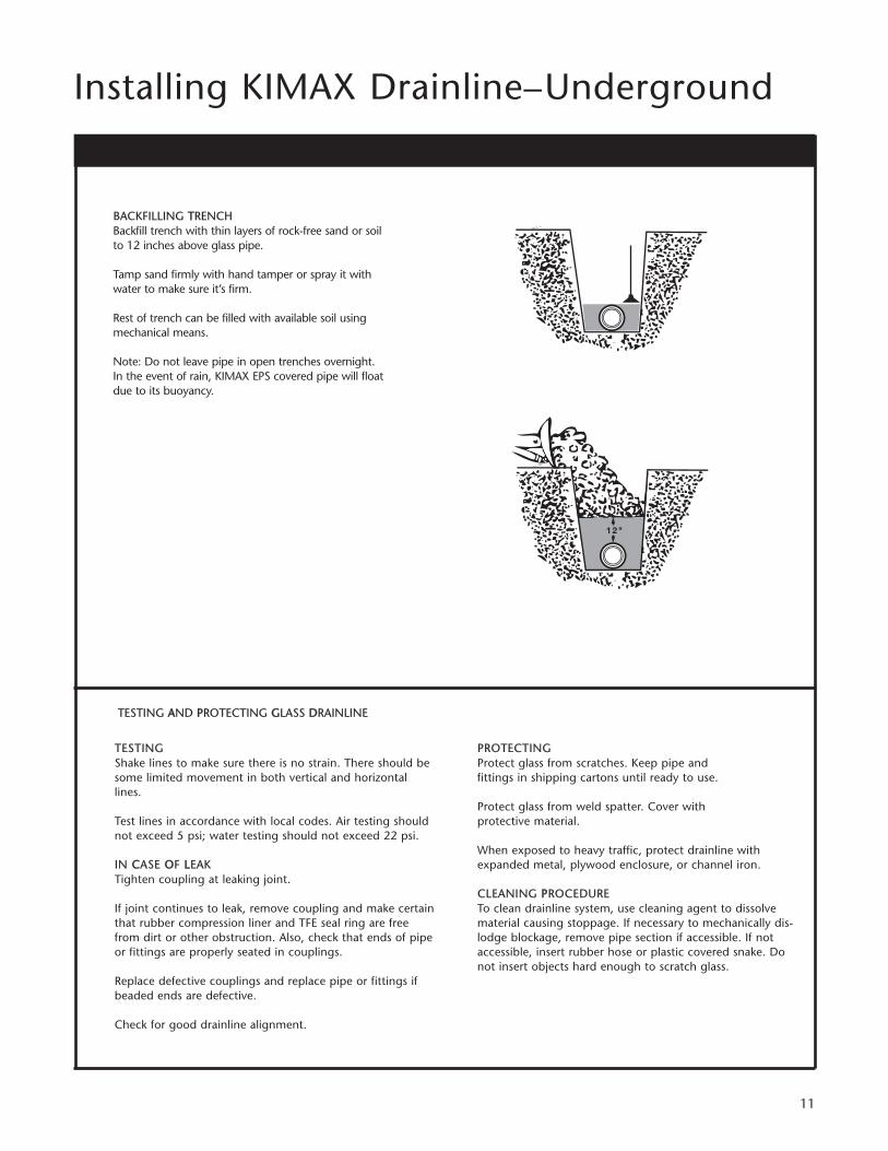
BACKFILLING TTRENCHBackfill trench with thin layers of rock-free sand or soil to 12 inches above glass pipe.
Tamp sand firmly with hand tamper or spray it with water to make sure it’s firm.
Rest of trench can be filled with available soil using mechanical means.
Note: Do not leave pipe in open trenches overnight. In the event of rain, KIMAX EPS covered pipe will float due to its buoyancy.
TESTINGShake lines to make sure there is no strain. There should besome limited movement in both vertical and horizontallines.
Test lines in accordance with local codes. Air testing shouldnot exceed 5 psi; water testing should not exceed 22 psi.
IN CCASE OOF LLEAKTighten coupling at leaking joint.
If joint continues to leak, remove coupling and make certainthat rubber compression liner and TFE seal ring are freefrom dirt or other obstruction. Also, check that ends of pipeor fittings are properly seated in couplings.
Replace defective couplings and replace pipe or fittings ifbeaded ends are defective.
Check for good drainline alignment.
PROTECTINGProtect glass from scratches. Keep pipe and fittings in shipping cartons until ready to use.
Protect glass from weld spatter. Cover with protective material.
When exposed to heavy traffic, protect drainline withexpanded metal, plywood enclosure, or channel iron.
CLEANING PPROCEDURETo clean drainline system, use cleaning agent to dissolvematerial causing stoppage. If necessary to mechanically dis-lodge blockage, remove pipe section if accessible. If notaccessible, insert rubber hose or plastic covered snake. Donot insert objects hard enough to scratch glass.
TESTING AAND PPROTECTING GGLASS DDRAINLINE

TubingSSCCHHOOTTTT NNoorrtthh AAmmeerriiccaa,, IInncc..555 Taxter RoadElmsford, NY 10523 USAPhone: (914)831-2200Fax: (914)831-2368E-mail: [email protected]/drainline
Oct
ober
200
6 Pr
inte
d in
the
USA