GEOTHERMAL WELL DRILLING - · PDF fileNgugi 2 Well drilling are inconclusive. The initial...
23
Presented at Short Course III on Exploration for Geothermal Resources, organized by UNU-GTP and KenGen, at Lake Naivasha, Kenya, October 24 - November 17, 2008. 1 GEOTHERMAL TRAINING PROGRAMME Kenya Electricity Generating Co., Ltd. GEOTHERMAL WELL DRILLING Paul K. Ngugi Kenya Electricity Generating Company Ltd. (KenGen) P.O. Box 785, Naivasha KENYA [email protected] ABSTRACT The drilling process complex as it may be rotate about breaking the ground and lifting the rock cuttings from the resulting hole. The ultimate geothermal drilling objective is to access the resource for exploitation. However, during resource development and exploitation, drilling is used to confirm existence of the resource, obtain data for resource assessment, provide adequate steam fuel for the power plant and resolve well production complications. Tri-cone tungsten carbide insert bits are very often used in geothermal drilling. Mobile and conventional land rigs are predominantly used in the geothermal drilling industry. The rigs are selected to technically fit the job at the lowest cost possible. The wells are made useful by casing them. Several casing string are used for each well. They are cemented to bond them to formation. Large production casing of 13 3/8” casing is increasing becoming common where large well outputs are encountered and directional drilling is being employed to target major faults that transmit fluids. 1. OVERVIEW OF THE DRILLING PROCESS Actual breaking of ground is achieved by use of a rock bit. The bit is rotated under weight. The bit both crashes and gouges the rock as it rotates. The broken rock pieces arising from the drilling are lifted from the bore by floating them in a circulating drilling fluid. This process continues until the well is completed. 2. REASONS FOR DRILLING The ultimate goal for drilling is to access the resource for exploitation. However, during the resource development and exploitation drilling serves various purposes. 2.1 Exploration The very first evaluation of a prospect is achieved through detailed surface reconnaissance. It is aimed at defining the resource by its key system characteristic namely: existence of a heat source in the form of hot magmatic body near earth surface, existence of hydrological system, characteristic of the geological setting and areal extent of the prospect (Figure 1). However, while the surface measurement and mapping and evaluation of the surface manifestations provide great insight as regards the resource characteristics and potential, results of the reconnaissance remain inferences and
Transcript of GEOTHERMAL WELL DRILLING - · PDF fileNgugi 2 Well drilling are inconclusive. The initial...
Presented at Short Course III on Exploration for Geothermal Resources,
organized by UNU-GTP and KenGen, at Lake Naivasha, Kenya, October 24 - November 17, 2008.
1
GEOTHERMAL TRAINING PROGRAMME Kenya Electricity Generating Co., Ltd.
GEOTHERMAL WELL DRILLING
Paul K. Ngugi
Kenya Electricity Generating Company Ltd. (KenGen)
P.O. Box 785, Naivasha
KENYA
ABSTRACT
The drilling process complex as it may be rotate about breaking the ground and
lifting the rock cuttings from the resulting hole. The ultimate geothermal drilling
objective is to access the resource for exploitation. However, during resource
development and exploitation, drilling is used to confirm existence of the resource,
obtain data for resource assessment, provide adequate steam fuel for the power
plant and resolve well production complications. Tri-cone tungsten carbide insert
bits are very often used in geothermal drilling. Mobile and conventional land rigs
are predominantly used in the geothermal drilling industry. The rigs are selected to
technically fit the job at the lowest cost possible. The wells are made useful by
casing them. Several casing string are used for each well. They are cemented to
bond them to formation. Large production casing of 13 3/8” casing is increasing
becoming common where large well outputs are encountered and directional
drilling is being employed to target major faults that transmit fluids.
1. OVERVIEW OF THE DRILLING PROCESS
Actual breaking of ground is achieved by use of a rock bit. The bit is rotated under weight. The bit
both crashes and gouges the rock as it rotates. The broken rock pieces arising from the drilling are
lifted from the bore by floating them in a circulating drilling fluid. This process continues until the
well is completed.
2. REASONS FOR DRILLING
The ultimate goal for drilling is to access the resource for exploitation. However, during the resource
development and exploitation drilling serves various purposes.
2.1 Exploration
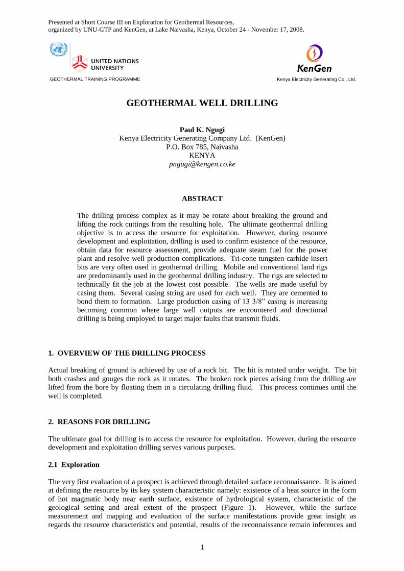
The very first evaluation of a prospect is achieved through detailed surface reconnaissance. It is aimed
at defining the resource by its key system characteristic namely: existence of a heat source in the form
of hot magmatic body near earth surface, existence of hydrological system, characteristic of the
geological setting and areal extent of the prospect (Figure 1). However, while the surface
measurement and mapping and evaluation of the surface manifestations provide great insight as
regards the resource characteristics and potential, results of the reconnaissance remain inferences and
Ngugi 2 Well drilling
are inconclusive. The initial employment of drilling in geothermal prospecting is aimed at providing
proof of exploitable steam and data required for further refining of the conceptual model.
2.2 Appraisal
Striking steam with the
first well while is exciting
opens up doors for more
questions. Having
confirmed existence of the
resource, the next question
is its technical, economic
and financial viability.
Further drilling (appraisal)
is therefore carried out to
delineate the resource and
establish production well
and reservoir fluids
characteristics.
2.3 Production and re-injection
At this stage of development, a decision to construct a plant is already made. The drilling is therefore
to provide sufficient steam to run the plant. Additional wells are drilled for reinjection purpose. One
reinjection well is required for every 4 to 5 production wells.
2.4 Make-up
After commissioning of the power plant, with time the reservoir surfers pressure decline which affects
well productivity. In addition, deposition may occur within the formation around the wells further
reducing wells productivity. With time, therefore further drilling is carried out to replenish the
reduced steam delivery.
2.5 Work-over
Two types of problem may arise during exploitation. Steam depletion in the shallow reservoir may
necessitate deepening of the initial wells or deposition of scales within the well bore may necessitate a
mechanical removal of the scales. These two cases require some form of drilling to accomplish.
3. BITS
3.1 Types of bits
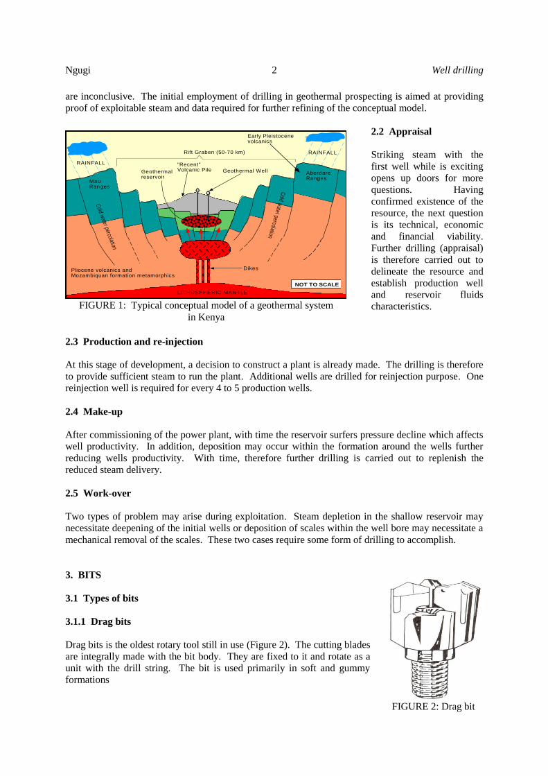
3.1.1 Drag bits
Drag bits is the oldest rotary tool still in use (Figure 2). The cutting blades
are integrally made with the bit body. They are fixed to it and rotate as a
unit with the drill string. The bit is used primarily in soft and gummy
formations
Cold w
ater percolation
Cold w
ater percolation
LITHOSPHERIC MANTLE
RAINFALL
RAINFALLRift Graben (50-70 km)
"Recent"Volcanic Pile
Pliocene volcanics andMozambiquan formation metamorphics
Early Pleistocenevolcanics
Geothermal Well
MauRanges
AberdareRanges
Dikes
NOT TO SCALE
Geothermalreservoir
FIGURE 1: Typical conceptual model of a geothermal system
in Kenya
FIGURE 2: Drag bit
Well drilling 3 Ngugi NgugiNgugi
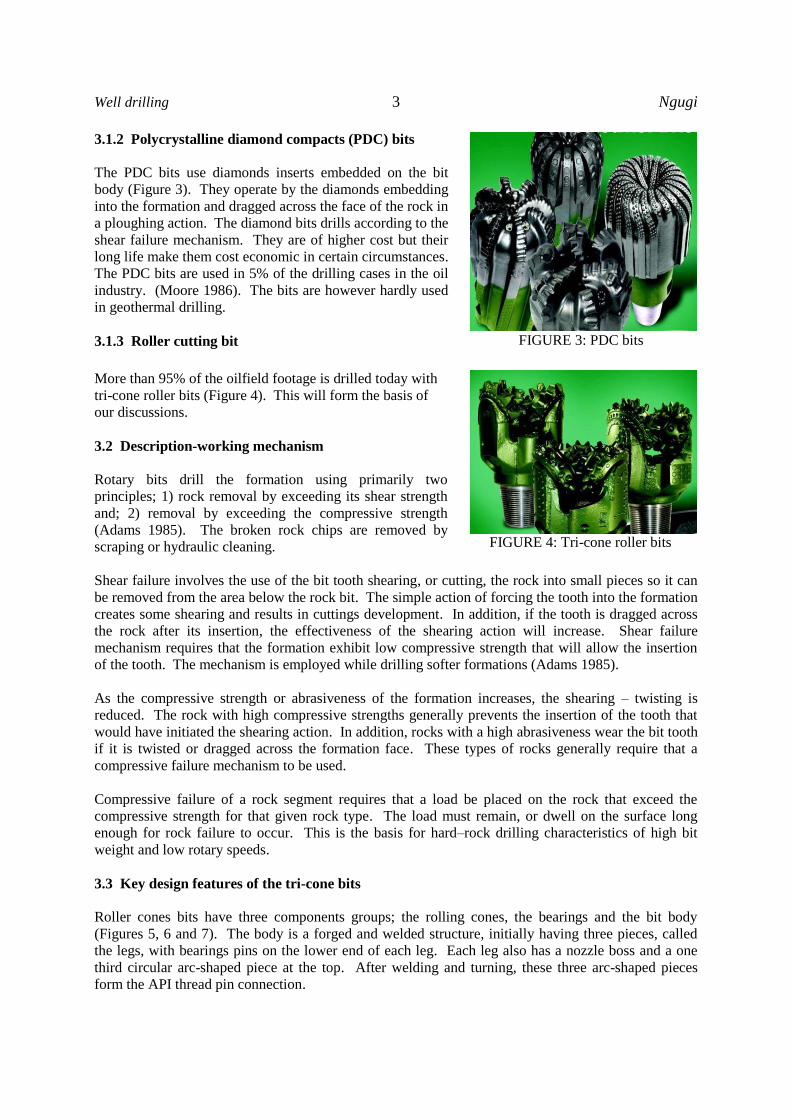
3.1.2 Polycrystalline diamond compacts (PDC) bits
The PDC bits use diamonds inserts embedded on the bit
body (Figure 3). They operate by the diamonds embedding
into the formation and dragged across the face of the rock in
a ploughing action. The diamond bits drills according to the
shear failure mechanism. They are of higher cost but their
long life make them cost economic in certain circumstances.
The PDC bits are used in 5% of the drilling cases in the oil
industry. (Moore 1986). The bits are however hardly used
in geothermal drilling.
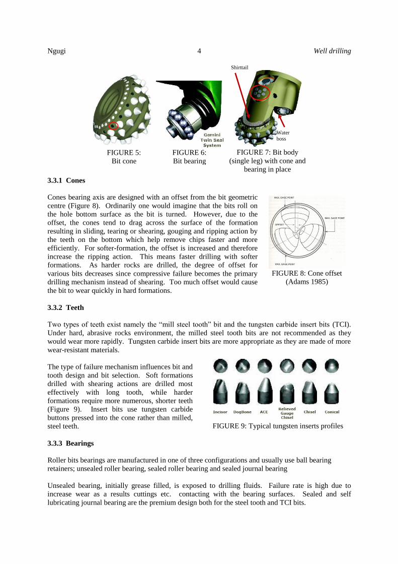
3.1.3 Roller cutting bit
More than 95% of the oilfield footage is drilled today with
tri-cone roller bits (Figure 4). This will form the basis of
our discussions.
3.2 Description-working mechanism
Rotary bits drill the formation using primarily two
principles; 1) rock removal by exceeding its shear strength
and; 2) removal by exceeding the compressive strength
(Adams 1985). The broken rock chips are removed by
scraping or hydraulic cleaning.
Shear failure involves the use of the bit tooth shearing, or cutting, the rock into small pieces so it can
be removed from the area below the rock bit. The simple action of forcing the tooth into the formation
creates some shearing and results in cuttings development. In addition, if the tooth is dragged across
the rock after its insertion, the effectiveness of the shearing action will increase. Shear failure
mechanism requires that the formation exhibit low compressive strength that will allow the insertion
of the tooth. The mechanism is employed while drilling softer formations (Adams 1985).
As the compressive strength or abrasiveness of the formation increases, the shearing – twisting is
reduced. The rock with high compressive strengths generally prevents the insertion of the tooth that
would have initiated the shearing action. In addition, rocks with a high abrasiveness wear the bit tooth
if it is twisted or dragged across the formation face. These types of rocks generally require that a
compressive failure mechanism to be used.
Compressive failure of a rock segment requires that a load be placed on the rock that exceed the
compressive strength for that given rock type. The load must remain, or dwell on the surface long
enough for rock failure to occur. This is the basis for hard–rock drilling characteristics of high bit
weight and low rotary speeds.
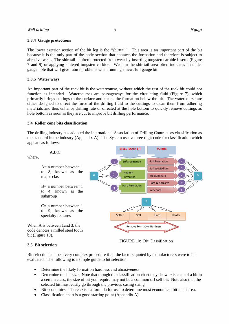
3.3 Key design features of the tri-cone bits
Roller cones bits have three components groups; the rolling cones, the bearings and the bit body
(Figures 5, 6 and 7). The body is a forged and welded structure, initially having three pieces, called
the legs, with bearings pins on the lower end of each leg. Each leg also has a nozzle boss and a one
third circular arc-shaped piece at the top. After welding and turning, these three arc-shaped pieces
form the API thread pin connection.
FIGURE 3: PDC bits
FIGURE 4: Tri-cone roller bits
Ngugi 4 Well drilling
3.3.1 Cones
Cones bearing axis are designed with an offset from the bit geometric
centre (Figure 8). Ordinarily one would imagine that the bits roll on
the hole bottom surface as the bit is turned. However, due to the
offset, the cones tend to drag across the surface of the formation
resulting in sliding, tearing or shearing, gouging and ripping action by
the teeth on the bottom which help remove chips faster and more
efficiently. For softer-formation, the offset is increased and therefore
increase the ripping action. This means faster drilling with softer
formations. As harder rocks are drilled, the degree of offset for
various bits decreases since compressive failure becomes the primary
drilling mechanism instead of shearing. Too much offset would cause
the bit to wear quickly in hard formations.
3.3.2 Teeth
Two types of teeth exist namely the “mill steel tooth” bit and the tungsten carbide insert bits (TCI).
Under hard, abrasive rocks environment, the milled steel tooth bits are not recommended as they
would wear more rapidly. Tungsten carbide insert bits are more appropriate as they are made of more
wear-resistant materials.
The type of failure mechanism influences bit and
tooth design and bit selection. Soft formations
drilled with shearing actions are drilled most
effectively with long tooth, while harder
formations require more numerous, shorter teeth
(Figure 9). Insert bits use tungsten carbide
buttons pressed into the cone rather than milled,
steel teeth.
3.3.3 Bearings
Roller bits bearings are manufactured in one of three configurations and usually use ball bearing
retainers; unsealed roller bearing, sealed roller bearing and sealed journal bearing
Unsealed bearing, initially grease filled, is exposed to drilling fluids. Failure rate is high due to
increase wear as a results cuttings etc. contacting with the bearing surfaces. Sealed and self
lubricating journal bearing are the premium design both for the steel tooth and TCI bits.
FIGURE 8: Cone offset
(Adams 1985)
FIGURE 9: Typical tungsten inserts profiles
FIGURE 5:
Bit cone
FIGURE 6:
Bit bearing
FIGURE 7: Bit body
(single leg) with cone and
bearing in place
Water boss
Shirttail
Well drilling 5 Ngugi NgugiNgugi
3.3.4 Gauge protections
The lower exterior section of the bit leg is the “shirttail”. This area is an important part of the bit
because it is the only part of the body section that contacts the formation and therefore is subject to
abrasive wear. The shirttail is often protected from wear by inserting tungsten carbide inserts (Figure
7 and 9) or applying sintered tungsten carbide. Wear in the shirttail area often indicates an under
gauge hole that will give future problems when running a new, full gauge bit
3.3.5 Water ways
An important part of the rock bit is the watercourse, without which the rest of the rock bit could not
function as intended. Watercourses are passageways for the circulating fluid (Figure 7), which
primarily brings cuttings to the surface and cleans the formation below the bit. The watercourse are
either designed to direct the force of the drilling fluid to the cuttings to clean them from adhering
materials and thus enhance drilling rate or directed at the hole bottom to quickly remove cuttings as
hole bottom as soon as they are cut to improve bit drilling performance.
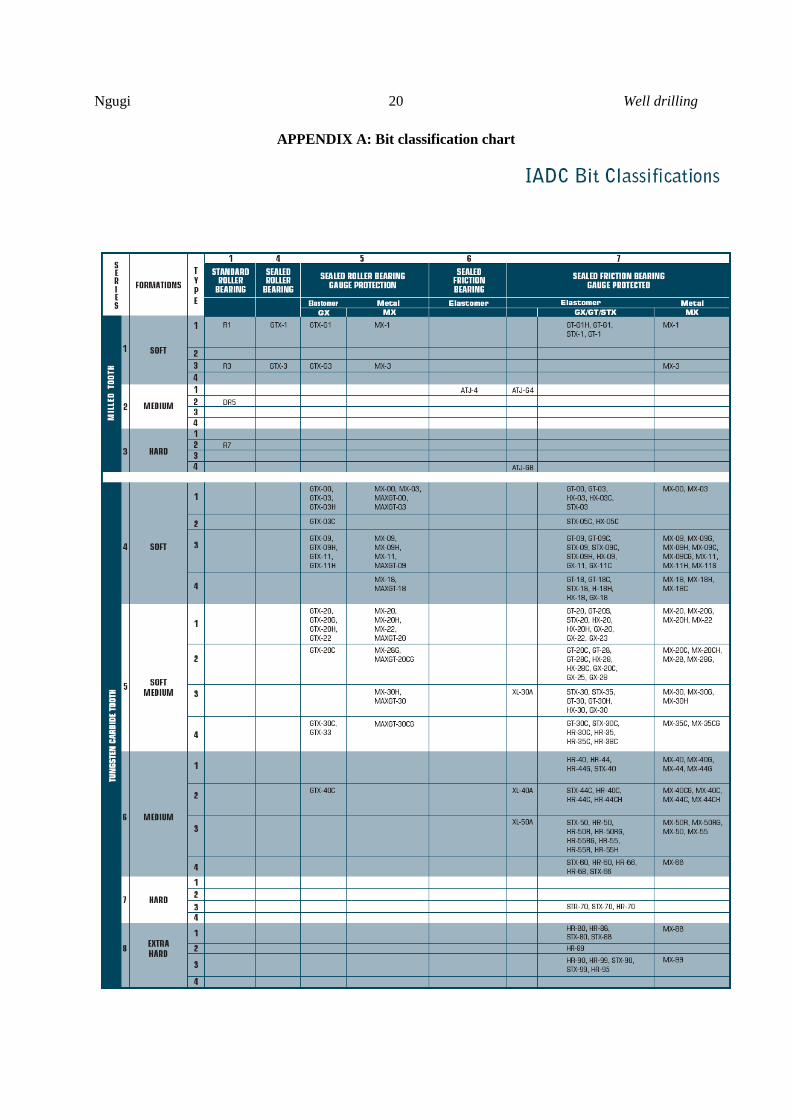
3.4 Roller cone bits classification
The drilling industry has adopted the international Association of Drilling Contractors classification as
the standard in the industry (Appendix A). The System uses a three-digit code for classification which
appears as follows:
A,B,C
where,
A= a number between 1
to 8, known as the
major class
B= a number between 1
to 4, known as the
subgroup
C= a number between 1
to 9, known as the
specialty features
When A is between 1and 3, the
code denotes a milled steel tooth
bit (Figure 10).
3.5 Bit selection
Bit selection can be a very complex procedure if all the factors quoted by manufacturers were to be
evaluated. The following is a simple guide to bit selection:
Determine the likely formation hardness and abrasiveness
Determine the bit size. Note that though the classification chart may show existence of a bit in
a certain class, the size of bit you require may not be a common off self bit. Note also that the
selected bit must easily go through the previous casing string.
Bit economics. There exists a formula for use to determine most economical bit in an area.
Classification chart is a good starting point (Appendix A)
Softer Soft Hard Harder
B
Relative Formation Hardness
1 Soft Formation
A 2
3
Medium
Formation
Hard Formation
4
STEEL TOOTH BIT
5
6
7
8
Soft Formation
Soft to Medium
Medium hard
Hard & Abrasive
Very hard
TCI BITS
A
FIGURE 10: Bit Classification
Ngugi 6 Well drilling
3.6 Failure pattern
Bits failure mainly arises from the key design features discussed above.
The cones could dislodge and be left in the hole. Good drillers would notice this by increased
torque. In addition, the cones could also lock again generating high torque.
The teeth could wear out or break rendering the bit performance poor
The bearings could burn out resulting to very loose cones
The bit shirttail could wear down resulting in under gauge hole
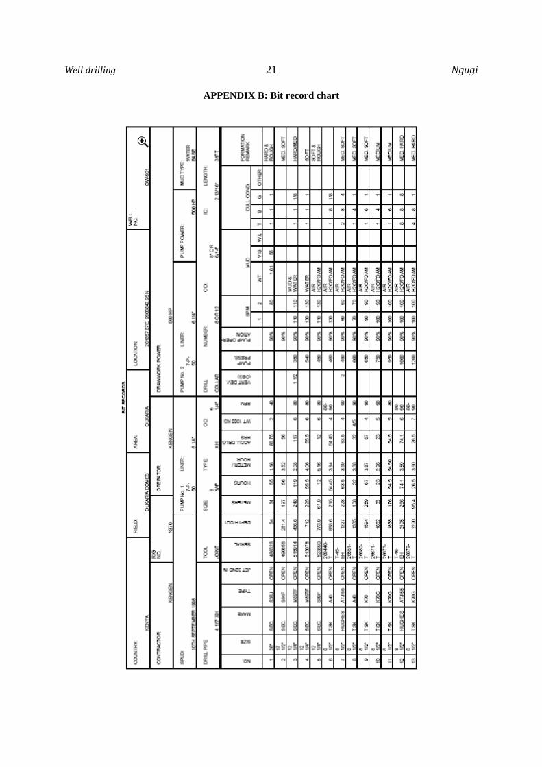
3.7 Bit records
Performance of various bits within a certain region is captured through proper bit records. Analysis of
the bit records (Appendix B) would give bits that give long life under the drilling conditions prevalent
in that region
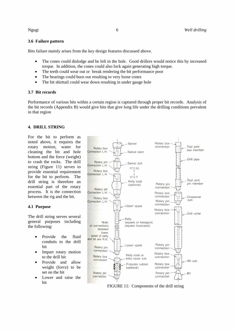
4. DRILL STRING
For the bit to perform as
noted above, it requires the
rotary motion, water for
cleaning the bit and hole
bottom and the force (weight)
to crash the rocks. The drill
string (Figure 11) serves to
provide essential requirement
for the bit to perform. The
drill string is therefore an
essential part of the rotary
process. It is the connection
between the rig and the bit.
4.1 Purpose
The drill string serves several
general purposes including
the following:
Provide the fluid
conduits to the drill
bit
Impart rotary motion
to the drill bit
Provide and allow
weight (force) to be
set on the bit
Lower and raise the
bit
FIGURE 11: Components of the drill string
Well drilling 7 Ngugi NgugiNgugi
4.2 Components and descriptions
4.2.1 Bit sub / NRV sub
Immediately above the bit is fitted a bit sub and may double as non-return valve (NRV) sub. The sub
is a piece of metal with a hole having female (box) thread on both sides which is about a 0.3 m (foot)
to 1 m (three feet) long. It is used to connect the bit and the first collar. In addition, it could have a
recess to accommodate a non-return valve. The non return valve ensures that fluid do not flow back
through the string to the rig floor. This especially is very important in geothermal because the fluids
could be dangerously hot for staff work at the rig floor.
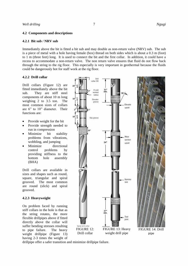
4.2.2 Drill collar
Drill collars (Figure 12) are
fitted immediately above the bit
sub. They are stiff steel
components of about 10 m long
weighing 2 to 3.5 ton. The
most common sizes of collars
are 6” to 10” diameter. Their
functions are:
Provide weight for the bit
Provide strength needed to
run in compression
Minimize bit stability
problems from vibrations,
wobbling, and jumping
Minimize directional
control problems by
providing stiffness to the
bottom hole assembly
(BHA)
Drill collars are available in
sizes and shapes such as round,
square, triangular and spiral
grooved. The most common
are round (slick) and spiral
grooved.
4.2.3 Heavyweight
On problem faced by running
stiff collars in the hole is that as
the string rotates, the more
flexible drillpipes above if fitted
directly above the collar will
suffer bending stresses resulting
to pipe failure. The heavy
weight drillpipe (Figure 13)
having 2-3 times the weight of
drillpipe offer a safer transition and minimize drillpipe failure.
FIGURE 13: Heavy
weight drill pipe
FIGURE 12:
Drill collar
FIGURE 14: Drill
pipe
Ngugi 8 Well drilling
4.2.4 Drillpipes
The drillpipes (Figure 14) are the longest section
of the drillstring. They consist of a tube body
welded to two tools joints with male (pin) and
female (box) threads. The most common sizes are
3 ½, 4 ½ and 5” diameter drill pipes.
4.2.5 Kelly saver sub
In general the Kelly saver sub is fitted between the
Kelly and drillpipe. It is a sacrificial tool to save
the Kelly from wear arising from frequent
connections.
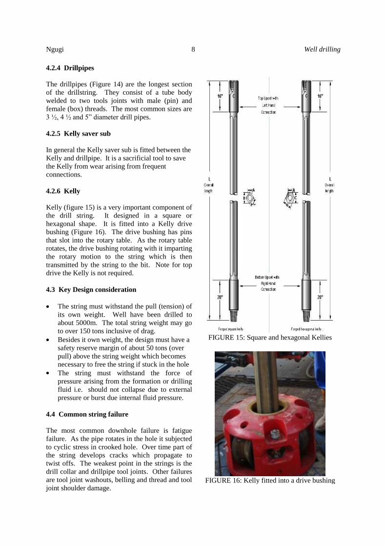
4.2.6 Kelly
Kelly (figure 15) is a very important component of
the drill string. It designed in a square or
hexagonal shape. It is fitted into a Kelly drive
bushing (Figure 16). The drive bushing has pins
that slot into the rotary table. As the rotary table
rotates, the drive bushing rotating with it imparting
the rotary motion to the string which is then
transmitted by the string to the bit. Note for top
drive the Kelly is not required.
4.3 Key Design consideration
The string must withstand the pull (tension) of
its own weight. Well have been drilled to
about 5000m. The total string weight may go
to over 150 tons inclusive of drag.
Besides it own weight, the design must have a
safety reserve margin of about 50 tons (over
pull) above the string weight which becomes
necessary to free the string if stuck in the hole
The string must withstand the force of
pressure arising from the formation or drilling
fluid i.e. should not collapse due to external
pressure or burst due internal fluid pressure.
4.4 Common string failure
The most common downhole failure is fatigue
failure. As the pipe rotates in the hole it subjected
to cyclic stress in crooked hole. Over time part of
the string develops cracks which propagate to
twist offs. The weakest point in the strings is the
drill collar and drillpipe tool joints. Other failures
are tool joint washouts, belling and thread and tool
joint shoulder damage.
FIGURE 15: Square and hexagonal Kellies
FIGURE 16: Kelly fitted into a drive bushing
Well drilling 9 Ngugi NgugiNgugi
4.5 Drill string management
Most of the failures can be prevented or be avoided with proper care of the string. The care includes:
Frequent string inspection. In Kenya, the string is inspected at least once every three wells drilled.
In some other countries inspection is carried out after drilling every well.
Use of thread protectors will eliminate thread and shoulder damage
Proper torquing will eliminate over torquing, belling, and washouts
Proper use of the right lubricants with eliminate thread galling (abnormal wear)
Proper storage and transportation will eliminate bending
5. DRILLING FLUIDS
5.1 Purpose of drilling fluids
Primarily, the drilling fluid function is to remove the cuttings from the bottom of the hole as fast as
they are created to facilitate further and efficient hole making process. In addition, the fluid transports
the cuttings to surface. The two functions constitute what is normally referred as hole cleaning. The
drilling fluid in real drilling situation is a complex subject with consideration ranging from the basic
hole cleaning, economics, availability, logistics, chemistry, safety, fluid dynamics and reservoir
management. As such the drilling fluids serve many functions.
The major functions include;
Cleaning of the hole bottom,
Carry cuttings to the surface
Cool and lubricate the bit and drillstring
Remove cuttings from muds at the surface
Minimize formation damage
Control formation pressure
Maintain hole integrity
Assist in well logging operations
Minimize corrosion of drillstring and casing
Minimize contamination problems
Minimize torque, drag and pipe sticking
Improve drilling rate
Cooling of the formation – unique for geothermal
5.2 Types of drilling fluids
The drilling fluids vary widely. The following table gives a classification of drilling fluids
(Chilingarian, 1983)
I. Water based drilling fluid.
a. Fresh water muds with little or no treatment. This include spud mud, inhibited muds
and natural clays
b. Chemical treated muds without calcium compounds added. This includes phosphate
muds, organic treated muds (lignite, chrome-lignosulfonate etc.)
c. Calcium treated muds which include lime, calcium chloride and gypsum
d. Salt-water muds which include sea water muds, saturated salt water muds
e. Oil emulsion muds i.e. oil in water
f. Special muds
Ngugi 10 Well drilling
II. Oil based drilling muds
a. Oil based muds
b. Inverted emulsion muds – water in oil
III. Gaseous drilling fluids
a. Air or natural gas
b. Aerated muds
c. Foams
5.3 Key drilling fluid properties
The three basic properties of drilling fluids that are mostly important for successful completion of a
well are:
a) Density as related to hydrostatic pressure.
b) Viscosity which affects the efficiency of the cutting lifting capacity of the drilling fluid
c) Filtrate loss – the loss of water component of the drilling fluid into formation
5.4 KenGen drilling fluid practice
5.4.1 26” Surface hole
The first section of the well is commenced with spud mud consisting of bentonite – lime with marsh
funnel viscosity of 60-80 sec marsh funnel viscosity and is drilled to 60 m.
If return circulation is lost and cannot be regained with loss control materials (LCM), drilling
continues blind (without circulation to surface) with water and high viscosity gel sweeps at every
connection or more frequently depending on the hole problems.
5.4.2 17 ½” intermediate hole
This section of well is drilled to a depth of about 250 to 300m with a bentonite –lime mud. If loss of
circulation returns occurs, attempts are made to regain it using LCM. If the loss cannot be healed,
drilling continues blind with water and frequently mud slug of high viscosity mud. The section is
drilled with high pumping rates on the hole to clean the hole. In extreme circumstance of poor
cleaning stiff foam is used.
5.4.3 12 ¼” production hole
This section that is drilled to between 500 to 1200 m is drilled with mud and when mud circulation
cannot be sustained, aerated water with foam is used.
5.4.4 8 ½” main hole
This section that is drilled normally to 2200 m to 3000 m is entirely drilled with water and when the
first signs of lost circulation appear, partial or total, aerated water with foam is used. No mud is ever
introduced to this section for protection of the formation. However, in one of our field, Olkaria West,
we have used aerated mud for this section due to severe sloughing problems. The in-going fluid is
maintained at a maximum temperature of 40°C, which is the maximum recommended operating
temperature for the pumps. Control of temperature is also critical for extending the bit life.
Well drilling 11 Ngugi NgugiNgugi
6. DRILLING RIGS
6.1 Basic functions
From a basic and simplistic
view, the rig can be seen as
that equipment that provides
the motive power to rotate the
bit, allow weight on the bit to
crash the rock beneath and
circulate the drilling fluid and
hence achieve the drilling
action. Achievement of these
basic rig functions requires
systems and processes where
various individual pieces of
equipment serve only as part of
the function in the whole
process and system.
Operational requirements and
economics dictate the
sophistication of drilling rigs.
6.2 Types of rigs
All rigs are categorized as either land or marine. Each of these categories, comprise various types of
drilling rigs.
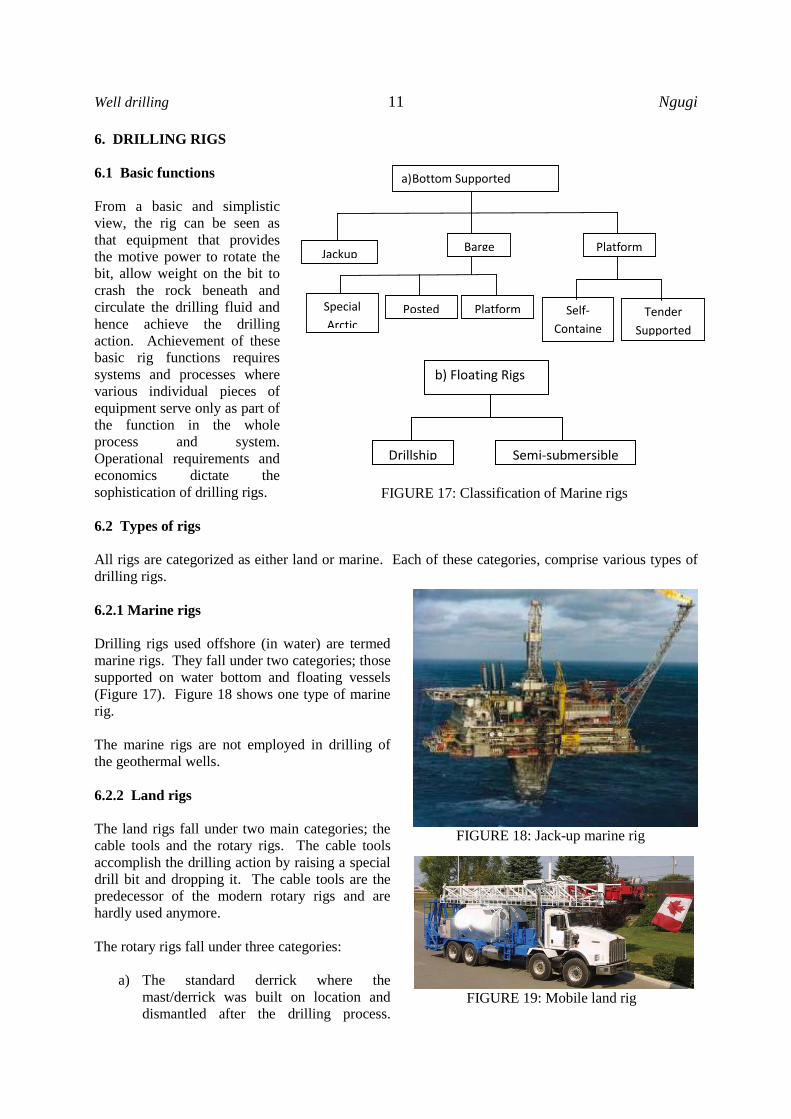
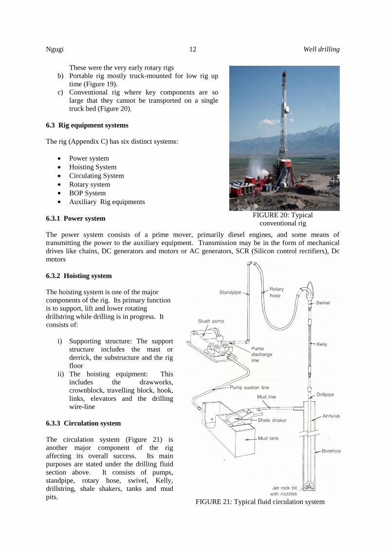
6.2.1 Marine rigs
Drilling rigs used offshore (in water) are termed
marine rigs. They fall under two categories; those
supported on water bottom and floating vessels
(Figure 17). Figure 18 shows one type of marine
rig.
The marine rigs are not employed in drilling of
the geothermal wells.
6.2.2 Land rigs
The land rigs fall under two main categories; the
cable tools and the rotary rigs. The cable tools
accomplish the drilling action by raising a special
drill bit and dropping it. The cable tools are the
predecessor of the modern rotary rigs and are
hardly used anymore.
The rotary rigs fall under three categories:
a) The standard derrick where the
mast/derrick was built on location and
dismantled after the drilling process.
a) Bottom Supported
Jackup Barge Platform
Self-
Containe
d
Tender
Supported
Posted Platform Special
Arctic
b) Floating Rigs
Drillship Semi-submersible
FIGURE 17: Classification of Marine rigs
FIGURE 18: Jack-up marine rig
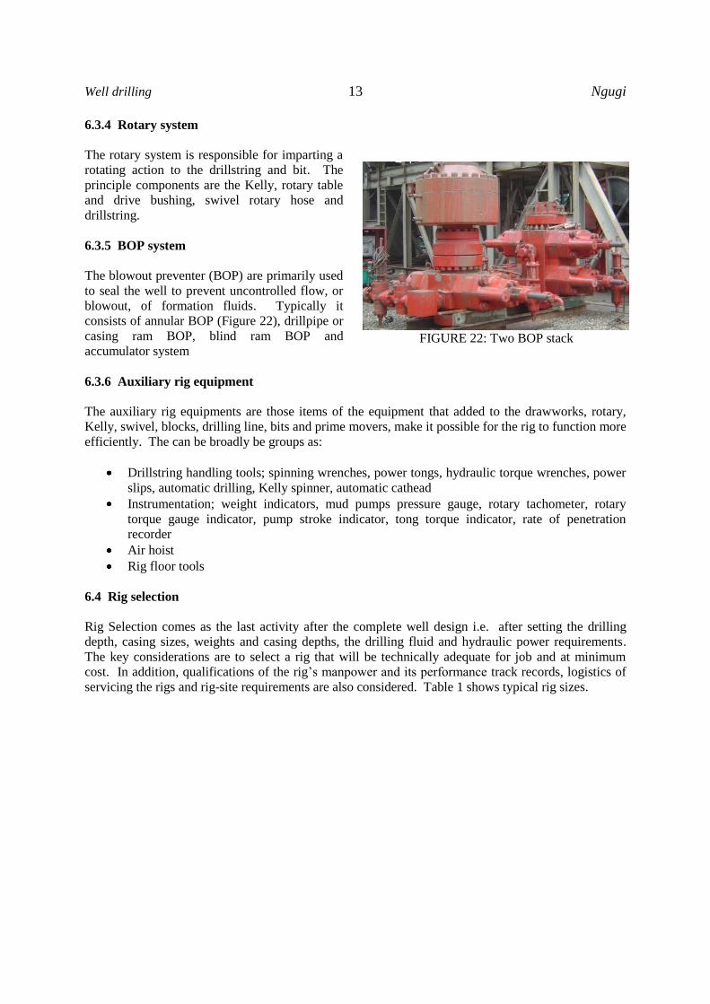
FIGURE 19: Mobile land rig
Ngugi 12 Well drilling
These were the very early rotary rigs
b) Portable rig mostly truck-mounted for low rig up
time (Figure 19).
c) Conventional rig where key components are so
large that they cannot be transported on a single
truck bed (Figure 20).
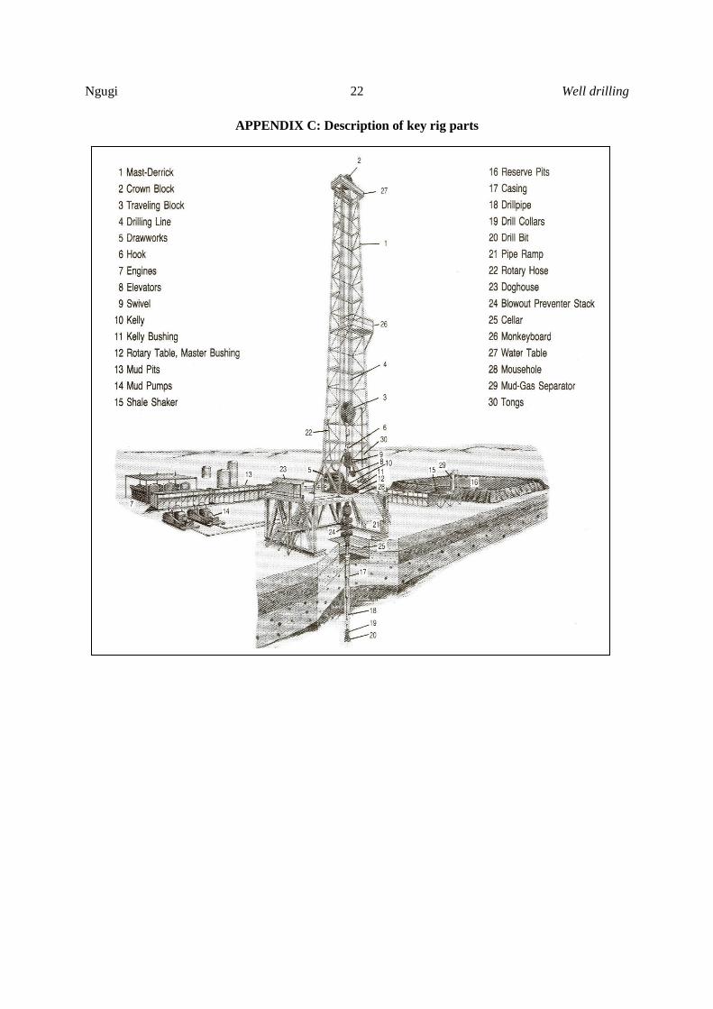
6.3 Rig equipment systems
The rig (Appendix C) has six distinct systems:
Power system
Hoisting System
Circulating System
Rotary system
BOP System
Auxiliary Rig equipments
6.3.1 Power system
The power system consists of a prime mover, primarily diesel engines, and some means of
transmitting the power to the auxiliary equipment. Transmission may be in the form of mechanical
drives like chains, DC generators and motors or AC generators, SCR (Silicon control rectifiers), Dc
motors
6.3.2 Hoisting system
The hoisting system is one of the major
components of the rig. Its primary function
is to support, lift and lower rotating
drillstring while drilling is in progress. It
consists of:
i) Supporting structure: The support
structure includes the mast or
derrick, the substructure and the rig
floor
ii) The hoisting equipment: This
includes the drawworks,
crownblock, travelling block, hook,
links, elevators and the drilling
wire-line
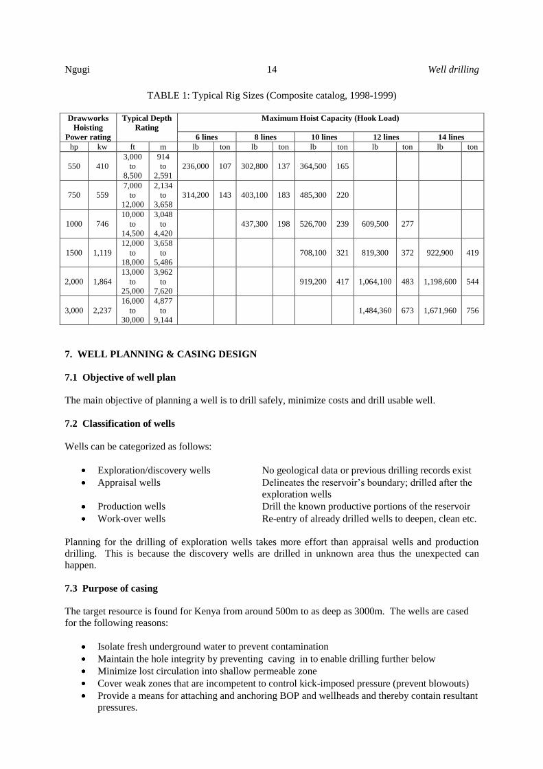
6.3.3 Circulation system
The circulation system (Figure 21) is
another major component of the rig
affecting its overall success. Its main
purposes are stated under the drilling fluid
section above. It consists of pumps,
standpipe, rotary hose, swivel, Kelly,
drillstring, shale shakers, tanks and mud
pits.
FIGURE 21: Typical fluid circulation system
FIGURE 20: Typical
conventional rig
Well drilling 13 Ngugi NgugiNgugi
6.3.4 Rotary system
The rotary system is responsible for imparting a
rotating action to the drillstring and bit. The
principle components are the Kelly, rotary table
and drive bushing, swivel rotary hose and
drillstring.
6.3.5 BOP system
The blowout preventer (BOP) are primarily used
to seal the well to prevent uncontrolled flow, or
blowout, of formation fluids. Typically it
consists of annular BOP (Figure 22), drillpipe or
casing ram BOP, blind ram BOP and
accumulator system
6.3.6 Auxiliary rig equipment
The auxiliary rig equipments are those items of the equipment that added to the drawworks, rotary,
Kelly, swivel, blocks, drilling line, bits and prime movers, make it possible for the rig to function more
efficiently. The can be broadly be groups as:
Drillstring handling tools; spinning wrenches, power tongs, hydraulic torque wrenches, power
slips, automatic drilling, Kelly spinner, automatic cathead
Instrumentation; weight indicators, mud pumps pressure gauge, rotary tachometer, rotary
torque gauge indicator, pump stroke indicator, tong torque indicator, rate of penetration
recorder
Air hoist
Rig floor tools
6.4 Rig selection
Rig Selection comes as the last activity after the complete well design i.e. after setting the drilling
depth, casing sizes, weights and casing depths, the drilling fluid and hydraulic power requirements.
The key considerations are to select a rig that will be technically adequate for job and at minimum
cost. In addition, qualifications of the rig’s manpower and its performance track records, logistics of
servicing the rigs and rig-site requirements are also considered. Table 1 shows typical rig sizes.
FIGURE 22: Two BOP stack
Ngugi 14 Well drilling
TABLE 1: Typical Rig Sizes (Composite catalog, 1998-1999)
Drawworks
Hoisting
Power rating
Typical Depth
Rating
Maximum Hoist Capacity (Hook Load)
6 lines 8 lines 10 lines 12 lines 14 lines
hp kw ft m lb ton lb ton lb ton lb ton lb ton
550 410
3,000
to
8,500
914
to
2,591
236,000 107 302,800 137 364,500 165
750 559
7,000
to
12,000
2,134
to
3,658
314,200 143 403,100 183 485,300 220
1000 746
10,000
to
14,500
3,048
to
4,420
437,300 198 526,700 239 609,500 277
1500 1,119
12,000
to
18,000
3,658
to
5,486
708,100 321 819,300 372 922,900 419
2,000 1,864
13,000
to
25,000
3,962
to
7,620
919,200 417 1,064,100 483 1,198,600 544
3,000 2,237
16,000
to
30,000
4,877
to
9,144
1,484,360 673 1,671,960 756
7. WELL PLANNING & CASING DESIGN
7.1 Objective of well plan
The main objective of planning a well is to drill safely, minimize costs and drill usable well.
7.2 Classification of wells
Wells can be categorized as follows:
Exploration/discovery wells No geological data or previous drilling records exist
Appraisal wells Delineates the reservoir’s boundary; drilled after the
exploration wells
Production wells Drill the known productive portions of the reservoir
Work-over wells Re-entry of already drilled wells to deepen, clean etc.
Planning for the drilling of exploration wells takes more effort than appraisal wells and production
drilling. This is because the discovery wells are drilled in unknown area thus the unexpected can
happen.
7.3 Purpose of casing
The target resource is found for Kenya from around 500m to as deep as 3000m. The wells are cased
for the following reasons:
Isolate fresh underground water to prevent contamination
Maintain the hole integrity by preventing caving in to enable drilling further below
Minimize lost circulation into shallow permeable zone
Cover weak zones that are incompetent to control kick-imposed pressure (prevent blowouts)
Provide a means for attaching and anchoring BOP and wellheads and thereby contain resultant
pressures.
Well drilling 15 Ngugi NgugiNgugi
Provide safe conduit for the reservoir fluids to the surface
To prevent cooling of the reservoir fluids by shallow cooler fluids
Prevent well collapse
7.4 Categories of casing strings
Before the well is drilled to completion, several strings of casing are run and cemented in place. The
actual number used is depended on the drilling safety and operational problems anticipated or
encountered. The types of casing strings are:
Surface casing: Mainly used to isolate the shallow loose formation to enable further
trouble free drilling below.
Intermediate casing: This may be more than one string. They primarily isolate the shallow
potable water from contamination, provide anchorage for the wellhead
and seal off zones of loss of drilling fluid. They also protect the
shallow formation from high downhole pressure thus prevent blowouts.
Production casing: This primarily act as the safe conduit for the reservoir fluid to surface,
protect shallow formation from deep reservoir pressure thus prevent
blowouts and isolate cooler shall water from degrading the reservoir
fluids
Slotted liner: This is primarily run to prevent the reservoir wellbore from collapsing
and blocking the well flow path.
7.5 Selecting casing depths
The first design task in preparing the well plan is
selecting the depths to which the casing will be run
and cement. The considerations made are the
geological conditions such as formation pressures and
formation fracture gradient. Other considerations are
policy and government regulations. Wells have been
drilled and cased too shallow or too deep.
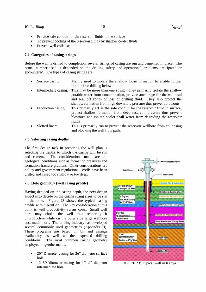
7.6 Hole geometry (well casing profile)
Having decided on the casing depth, the next design
aspect is to decide on the casing string sizes to be run
in the hole. Figure 23 shows the typical casing
profile within KenGen. The key consideration at this
point is well productivity versus costs. Small well
bore may choke the well thus rendering it
unproductive while on the other side large wellbore
cost much more. The drilling industry has developed
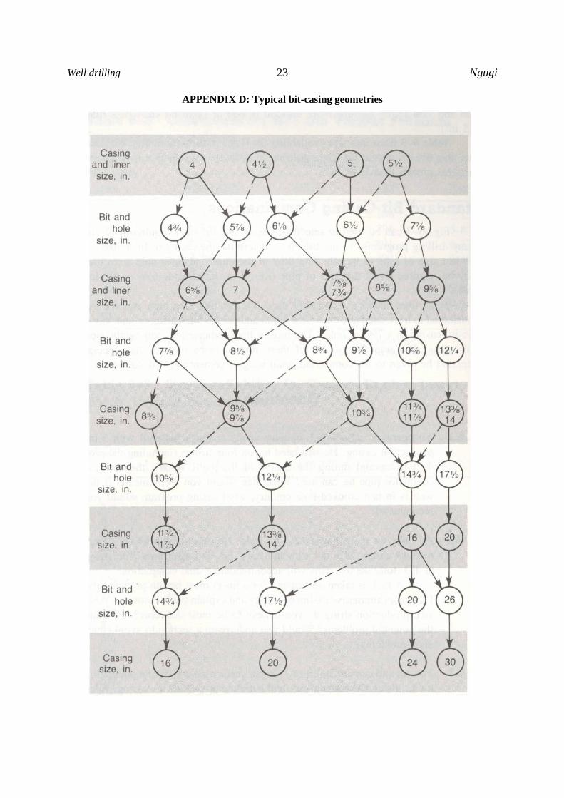
several commonly used geometries (Appendix D).
These programs are based on bit and casings
availability as well as the expected drilling
conditions. The most common casing geometry
employed in geothermal is:
20” Diameter casing for 26” diameter surface
hole
13 3/8”diameter casing for 17 ½” diameter
intermediate hole
FIGURE 23: Typical well in Kenya
Ngugi 16 Well drilling
9 5/8” casing for the 12 ¼” production hole
7” slotted liner for the 8 1/2” main hole
The considerations made are casing inner and outer diameter, coupling (collar) diameter and bit sizes.
Sufficient allowance is made to allow flow area between the casing and wellbore to reduce washouts
while provide sufficient velocity for drilling fluid to lift cuttings.
7.7 Casing design
The casing is used for protection during the entire life of the well and therefore it is designed to
withstand many severe operating conditions.
Common problems often considered for casing
design when drilling are kicks, lost circulation,
stuck pipe, wear, hydrogen sulphide environment
and salt. Just like the drilling string, the casing is
designed to with stand burst, collapse, tension
forces and biaxial effects (combined effects).
In General the thicker the casing the more
resistance it is to the above factors. However, the
more the well cost.
8. CEMENTING
8.1 Purpose
Cementing of casings is one of the critical
operations during the drilling of a well that affects
the producing life of a well. Casing strings are
usually cemented in the hole to:
Bond the casing to the formation
Protect deeper hot producing zones from
being cooled by cooler water emanating
shallow bearing zones
Minimize the danger of blowouts from
deeper high pressure zones by isolating
weaker shallow zones
To isolate shallow troublesome formation
to enable deeper drilling
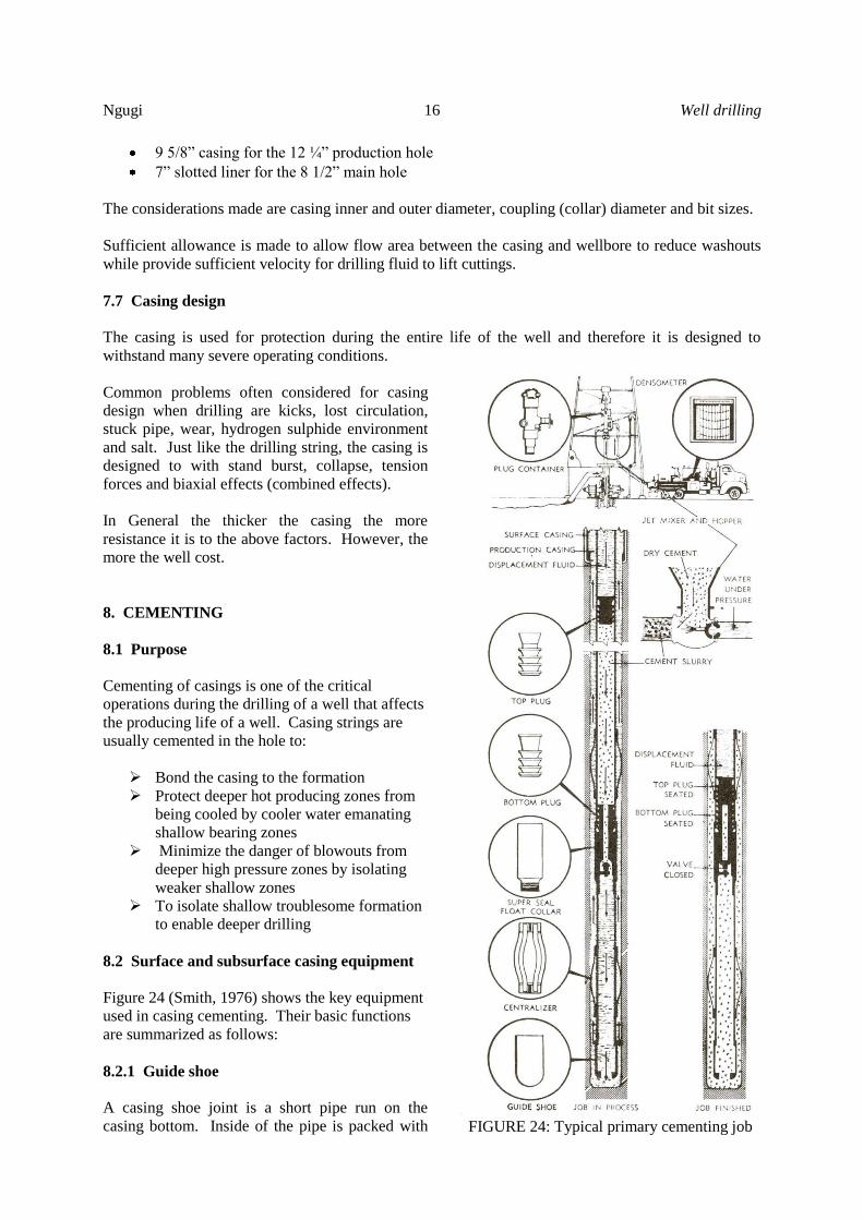
8.2 Surface and subsurface casing equipment
Figure 24 (Smith, 1976) shows the key equipment
used in casing cementing. Their basic functions
are summarized as follows:
8.2.1 Guide shoe
A casing shoe joint is a short pipe run on the
casing bottom. Inside of the pipe is packed with
FIGURE 24: Typical primary cementing job
Well drilling 17 Ngugi NgugiNgugi
drillable but hard material shaped in a rounded nose provided with a hole which is used to guide the
casing into the hole through crooked sections. The shoe is screwed on the casing and is glued with a
thread locking compound to avoid inadvertent loosening while being run in the hole.
8.2.2 Float collar
The float collar is placed one or two casing joints above the guide shoe. The collar serves as a stop for
the cement wiper plug such that all the cement is not inadvertently pumped out of the casing and
diluting the cement at the shoe a situation that would result to a poor cementing job. It is fitted with a
ball or spring-loaded backpressure valve. The valve prevents well bore fluid entering the casing while
allowing pumped fluid through the casing to pass through.
8.2.3 Casing centralizers
The uniformity of the cement sheath around the pipe determines to a great extent the effectiveness of
the seal between the wellbore and the casing. Centralizers are placed on the exterior of the casing
string to centralize the casings within the wellbore in an effort to attain cement around the casing in
the whole string. There are several types of centralizers with the bow spring type being the most
common. The centralizers are normally hinged to aid in fitting them round the casing.
8.2.4 Cementing plugs
Drillable Plugs are used to separate cement and water/mud while displacing cement within the casing.
8.2.5 Cementing head
Cementing heads are containers for the cement plugs. The plugs are retained until when the cement
pumping is over and then released. They are also used as connections of the fluid hoses from the
pumps and the top of casing.
8.3 Primary cementing procedure
Primary cementing is the most important of all cement Jobs. It is performed immediately after the
casing is run into the hole. The objective is to deliver quality cement behind the casing that is the
annulus between the casing and the formation or previous casing strings. Two methods are normally
employed for the primary cement job namely the conventional and stub-in (stinger) method.
The conventional method could be single or multiple stage technique. In the single stage cementing
technique, cement slurry is mixed in the pumping truck and the cement slurry pumped inside the
casing string through the cementing head. After the entire slurry volume has been pumped, the cement
slurry within the casing is displaced to the float collar using water. The two are separated by use of
cementing plugs (top). The cement is prevented from flowing back by the ball valve fitted on the
casing float collar or casing float shoe or using a valve fitted to the cementing head.
After landing casing and before commencing pumping cement slurry, a drilling fluid is circulated in
the hole. The purpose of the drilling fluid is:
To ensure the flow path is clear. Several factors can cause blockage of the fluid path way.
These are cuttings, sloughing/ collapsing formation, boulders or the casing could seat on the
hole bottom if not properly landed.
To clean the well. If hole cleaning problems had been experienced previous to running the
casing, then a high viscous mud would be pumped to lift the cuttings from the hole bottom
Ngugi 18 Well drilling
To cool the well bore. Cement setting is affected by high temperature. In severe situations
the cement can set instantly on contact with steam stopping any further cement flow leading to
failed cementing job. Cold water is normally circulated at least for 30 minutes before
commencing cementing.
To scrap of mud wall cakes.
8.4 Factors that influence slurry design
There are many factors considered in primary cement job slurry design. The key ones include the well
depth, well bore temperature, pumping time, slurry density, strength of cement required to support the
pipe, lost circulation, filtrate loss and quality of mixing water.
The mixing water should be clean for the resulting slurry to develop the desired properties in particular
strength. Deep wells require fairly long time to carry out and complete the cementing jobs. This
means that the cement slurry must remain pumpable for the entire period during the cementing job.
Temperature and pressure accelerates the setting of cement slurry. Therefore it is very important to
take into consideration the effects of these parameters. Major losses of cement can result to very
expensive jobs both on lost cement and operation time. The density of the slurry is designed to
effectively control blowouts and to displace mud from the well bore.
8.5 Cementing additives
The desired properties for a specific cement slurry design are achieved by adding various chemicals
and materials (additives) that alter the ordinary Portland cement normal behaviour. The additives are
classified as follows:
i. Accelerators
ii. Lightweight materials
iii. Heavy weight materials
iv. Retarders
v. Lost circulation control materials
vi. Filtration- control agents
vii. Friction reducers and
viii. Specialty materials
Accelerators are used to shorten the cementing thickening time, light weight additives are added to the
slurry to reduce the slurry density while the heavy weight additives are added to increase the density.
The cement retarders are added to the cement to increase the slurry thickening time for long jobs while
friction reducers are added to the cement slurry to improve flow properties of the slurry. The lost
circulation control materials are added to the slurry to bridge minor formation fractures that would
take up cement while filtration control additives are added to reduce the water loss from the slurry to
the formation which would result to early thickening of the cement slurry.
8.6 Open-hole plug jobs
Cementing jobs are not limited to casing operations only. They are often times also used to plug
major drilling fluid loss zones. Major fluid circulation losses results to loss of data obtained from
cutting. They further results to poor hole cleaning and the rock cuttings repeatedly fall back into the
well bore as soon as the pumps are stopped. The falling cuttings at time result into stack drill string.
Cement slurry without additives is prepared and placed at the point where the losses are and the
cement is allowed to set thereby sealing out the formation fractures.
Well drilling 19 Ngugi NgugiNgugi
9. WELL OUTPUT OPTIMIZATION
The objective of drilling a well is to obtain the maximum output from the well. Where good
permeability have been encountered, it has been shown that the production casing size of 9 5/8”
diameter has inhibited well output in some cases. In such fields, it is becoming increasing more
common to use the 13 3/8” casing as the production casing.
It is now a common practice to drill directional wells which target faults that control fluid movement
with the objective of increasing well output.
Over 60% of the well cost is incurred drilling the upper section of the well to the production casing
(500 - 1500m). Drilling of forked or multi-legged well completions may become increasing common
as a way to optimize investment economics.
10. FISHING
Fishing takes upto 20% of drilling well. Fishing is the process of removal of objects or obstructions
that impedes further drilling. Each rig is equipped with some form of fishing tools. Fishing jobs
require high skill and specialized equipment. Most companies find it more economic to rely on
service companies to furnish the tools and specialized personnel when need arise.
11. MANAGEMENT OF DRILLING PROCESS
Drilling can be broken into the drilling operations that involve the actual drilling process and running
of casings, cementing process, specialized drilling fluids operations, e.g. air drilling services,
directional drilling services, well logging, drill pipe inspection services and sometimes rig moving
services. Various contracts are drawn to avail all these services depending on the well design and
anticipated drilling problems. A representative of the company is appointed to represent the client on
a 24 hr basis. Other specialized requirements like fishing are obtained as and when need arise.
REFERENCES
Adams, N.J, 1985: Drilling Engineering, A complete Well Planning Approach, Penn Well Publishing
Company, Tulsa, Olkahoma, USA, 960pp.
Chilingarian G.V. and Vorabutr, p., 1983: Drilling and Drilling fluids, Updated \textbook Edition,
Elsevier Science Publisher P. V., Amsterdam, The Netherlands, 801pp.
Composite catalog 1999: Continental Emsco General Catalog, Gulf Publishing Company Publication,
Houston Texas, USA, 1.
Moore, P.L., 1986: Drilling Practices Manual, Second Edition, Penn Well Publishing Company,
Tulsa, Olkahoma, USA, 586pp.
Smith K.D., 1976: Cementing, Second Printing, Millet the Printer .Inc. , Dallas, Texas, 184pp.
Ngugi 20 Well drilling
APPENDIX A: Bit classification chart
Well drilling 21 Ngugi NgugiNgugi
APPENDIX B: Bit record chart
Ngugi 22 Well drilling
APPENDIX C: Description of key rig parts
Well drilling 23 Ngugi NgugiNgugi
APPENDIX D: Typical bit-casing geometries