GEOTHERMAL DRILLING AN INRODUCTION
33
GEOTHERMAL DRILLING – AN INRODUCTION CommTECH Course 2021 Online Edition Sub Course (E/F/G/H) : (Febry R Firdaus) Institut Teknologi Sepuluh Nopember (ITS) Surabaya - Indonesia
Transcript of GEOTHERMAL DRILLING AN INRODUCTION
GEOTHERMAL DRILLING – AN INRODUCTION
CommTECH Course 2021 Online Edition
Sub Course (E/F/G/H) :
(Febry R Firdaus)
Institut Teknologi Sepuluh Nopember (ITS)
Surabaya - Indonesia
ITS
Global
Engagement
2
Content
General Drilling Overview
Drilling Project Team
Geothermal Drilling Challenges
Drilling Fluids for Geothermal Drilling
ITS
Global
Engagement
3
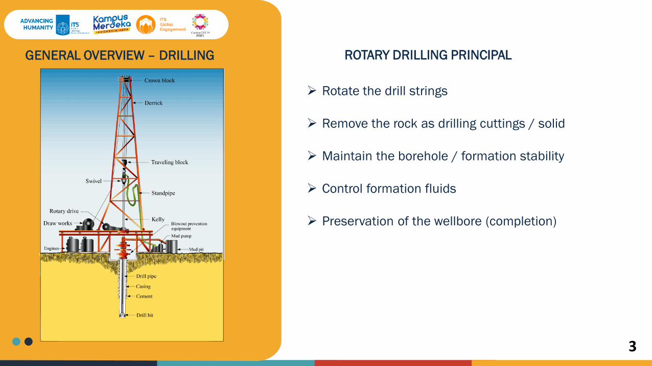
GENERAL OVERVIEW – DRILLING ROTARY DRILLING PRINCIPAL
Rotate the drill strings
Remove the rock as drilling cuttings / solid
Maintain the borehole / formation stability
Control formation fluids
Preservation of the wellbore (completion)

ITS
Global
Engagement
4
GENERAL OVERVIEW – DRILLING DRILLING RIG SYSTEM
Hoisting System
Rotating System
Circulating System
Blowout Prevention System
Power System
ITS
Global
Engagement
5
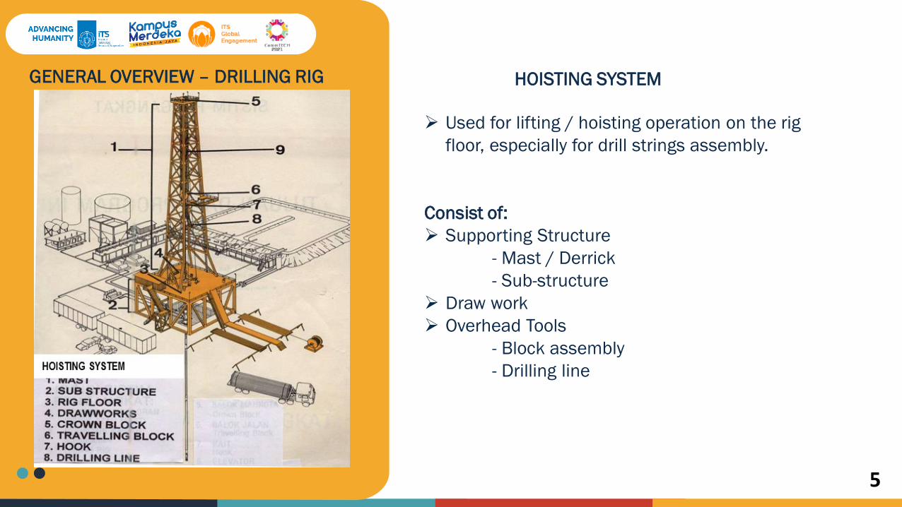
GENERAL OVERVIEW – DRILLING RIG HOISTING SYSTEM
Used for lifting / hoisting operation on the rig
floor, especially for drill strings assembly.
Consist of:
Supporting Structure
- Mast / Derrick
- Sub-structure
Draw work
Overhead Tools
- Block assembly
- Drilling line
ITS
Global
Engagement
6
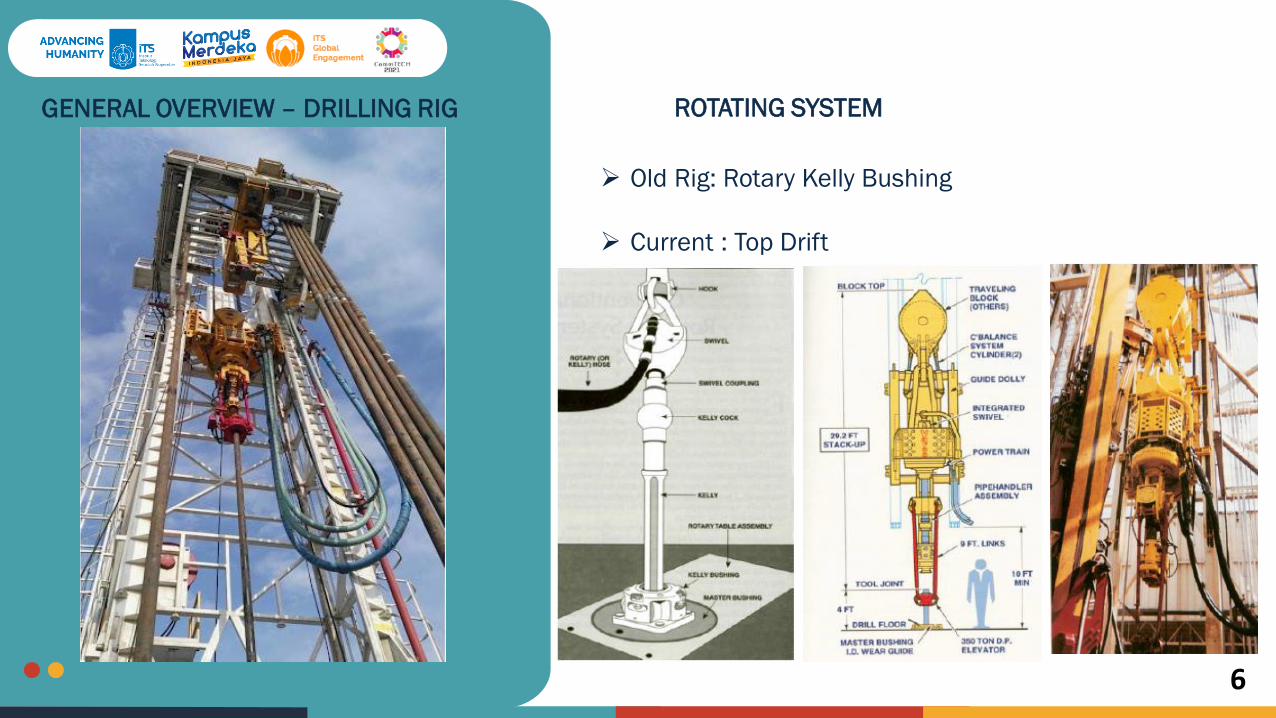
ROTATING SYSTEM
Old Rig: Rotary Kelly Bushing
Current : Top Drift
GENERAL OVERVIEW – DRILLING RIG
ITS
Global
Engagement
7
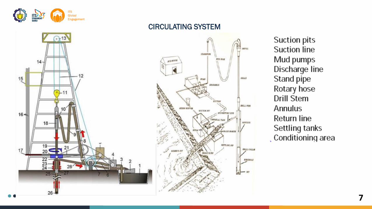
CIRCULATING SYSTEM

ITS
Global
Engagement
8
WASTE PROCESSING
WELL BORESOLIDS
CONTROLMIXING AND
ADDITION
FRESH FLUID & ADDITIVES
DRILLING FLUID
DRILLING SOLIDS +
FLUID
GAS / STEAM
REMOVALFLARING
CIRCULATING SYSTEM

ITS
Global
Engagement
9

ITS
Global
Engagement
10
GENERAL OVERVIEW – DRILLING RIG
BLOWOUT PREVENTION SYSTEM
Used to control kick / blowout by closing the wellbore
rapidly for securing.
Consist of:
BOP Stack
Accumulator unit
Choke line
Kill line
Choke manifold

ITS
Global
Engagement
11

ITS
Global
Engagement
12
TEAM OF DRILLING PROJECT
ITS
Global
Engagement
13
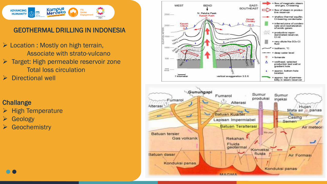
GEOTHERMAL DRILLING IN INDONESIA
Location : Mostly on high terrain,
Associate with strato-vulcano
Target: High permeable reservoir zone
Total loss circulation
Directional well
Challange
High Temperature
Geology
Geochemistry
ITS
Global
Engagement
14
ITS
Global
Engagement
15
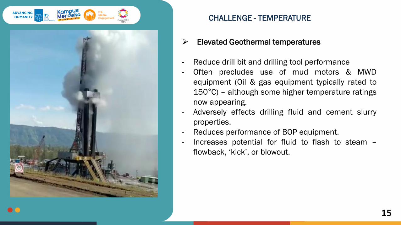
CHALLENGE - TEMPERATURE
Elevated Geothermal temperatures
- Reduce drill bit and drilling tool performance
- Often precludes use of mud motors & MWD
equipment (Oil & gas equipment typically rated to
150°C) – although some higher temperature ratings
now appearing.
- Adversely effects drilling fluid and cement slurry
properties.
- Reduces performance of BOP equipment.
- Increases potential for fluid to flash to steam –
flowback, ‘kick’, or blowout.

ITS
Global
Engagement
16
CHALLENGE - GEOLOGY
Geothermal systems are found in a wide variety of geological environments and rock types
Pacific basin fields -predominantly rhyolitic or andesitic volcanismIceland – widespread extensively fractured basaltsLarderello, Italy – metamorphic rocksGeysers, California – fractured greywacke
Common denominator – highly permeable, fractured and faulted. Permeability – a fundamental prerequisite for a geothermal system to exist
Typically permeability not only in reservoir structure, but in overlying formations as well

ITS
Global
Engagement
17
CHALLENGE - GEOLOGY
Under Pressured
A characteristic of most geothermal systems -The static reservoir fluid pressure is less than that exerted by a column of cold water from the surface - the system is “under pressured”
Static water level often 200 m to 400 m below surface.
Drilling through permeable and under pressured zones – frequent and most often total loss of circulation of drilling fluid.
Near surface formations often low bulk density pumices, ashes, breccias – permeable, non-consolidated, friable – with low fracture gradient – low resistance to blow out.
ITS
Global
Engagement
18
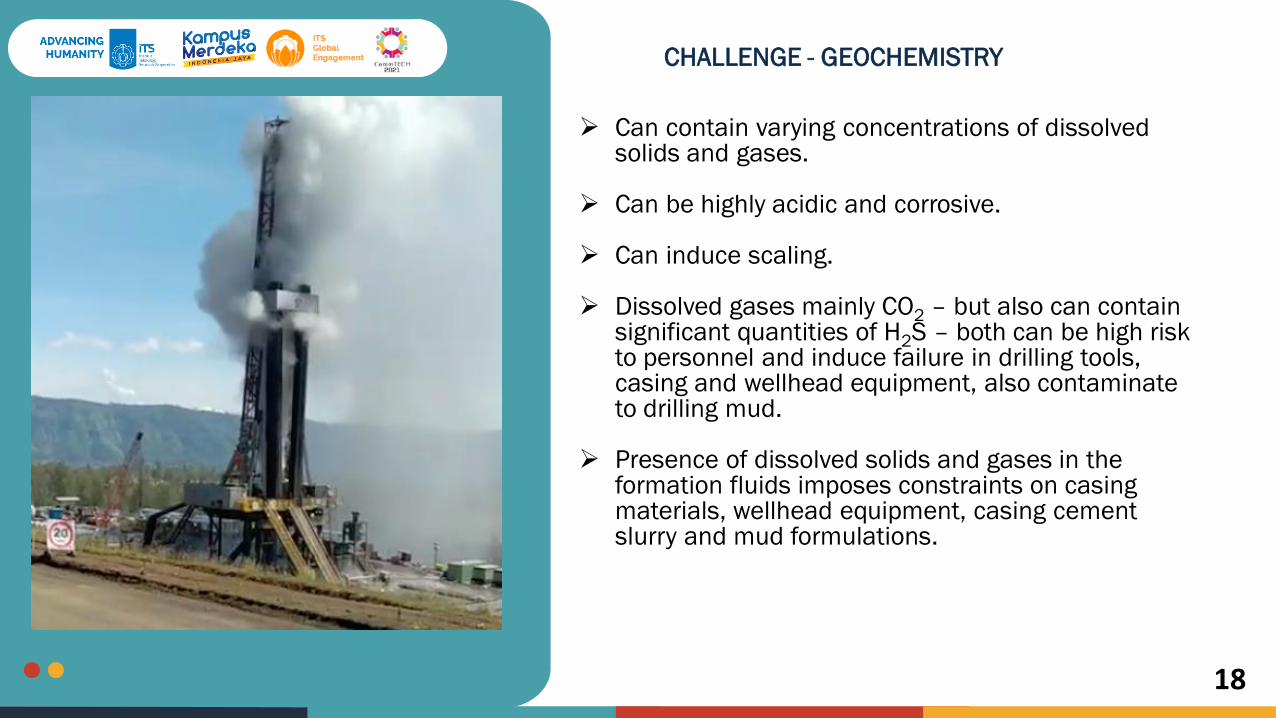
CHALLENGE - GEOCHEMISTRY
Can contain varying concentrations of dissolved solids and gases.
Can be highly acidic and corrosive.
Can induce scaling.
Dissolved gases mainly CO2 – but also can contain significant quantities of H2S – both can be high risk to personnel and induce failure in drilling tools, casing and wellhead equipment, also contaminate to drilling mud.
Presence of dissolved solids and gases in the formation fluids imposes constraints on casing materials, wellhead equipment, casing cement slurry and mud formulations.
ITS
Global
Engagement
19
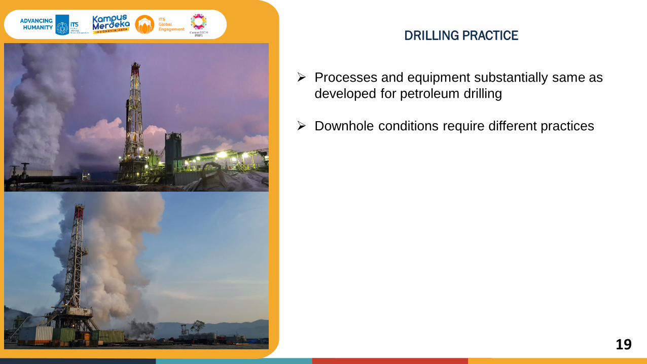
DRILLING PRACTICE
Processes and equipment substantially same as
developed for petroleum drilling
Downhole conditions require different practices
ITS
Global
Engagement
20
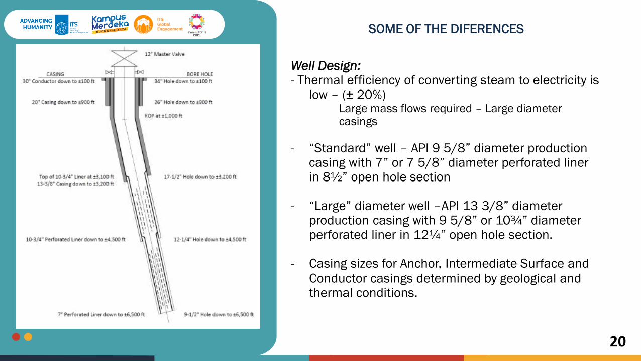
SOME OF THE DIFERENCES
Well Design:- Thermal efficiency of converting steam to electricity is
low – (± 20%) Large mass flows required – Large diameter casings
- “Standard” well – API 9 5/8” diameter production casing with 7” or 7 5/8” diameter perforated liner in 8½” open hole section
- “Large” diameter well –API 13 3/8” diameter production casing with 9 5/8” or 10¾” diameter perforated liner in 12¼” open hole section.
- Casing sizes for Anchor, Intermediate Surface and Conductor casings determined by geological and thermal conditions.
ITS
Global
Engagement
21
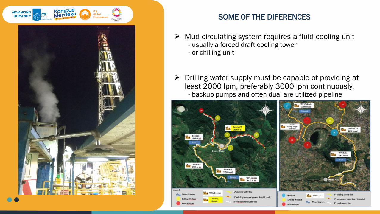
Mud circulating system requires a fluid cooling unit- usually a forced draft cooling tower- or chilling unit
Drilling water supply must be capable of providing at least 2000 lpm, preferably 3000 lpm continuously.- backup pumps and often dual are utilized pipeline
SOME OF THE DIFERENCES
ITS
Global
Engagement
22
ITS
Global
Engagement
23
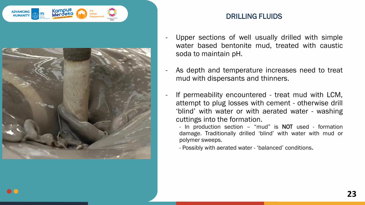
DRILLING FLUIDS
- Upper sections of well usually drilled with simplewater based bentonite mud, treated with causticsoda to maintain pH.
- As depth and temperature increases need to treatmud with dispersants and thinners.
- If permeability encountered - treat mud with LCM,attempt to plug losses with cement - otherwise drill‘blind’ with water or with aerated water - washingcuttings into the formation.
- In production section – “mud” is NOT used - formationdamage. Traditionally drilled ‘blind’ with water with mud orpolymer sweeps.
- Possibly with aerated water - ‘balanced’ conditions.

ITS
Global
Engagement
24
DRILLING FLUIDS FUCTION
1. Control formation pressure
2. Maintain wellbore stability
3. Seal permeable formation
4. Minimize formation damage
5. Cool, lubricate, and support the bit and drill strings
6. Transmit hydraulic energy to downhole tools and bit
7. Facilitate formation evaluation
8. Control corrosion
9. Suspend and release cuttings
10. Remove cutting from the well

ITS
Global
Engagement
25
WATER BASE MUD COMPOSITION
Drilling fluids compositions consists of two phases:
a) Continuous phase: represents the base fluid.b) Discontinuous phase: represent the additives that can be added to the fluid.
Example: WBM Formulation 26” Hole section
Example: WBM Formulation 17.5” Hole section
ITS
Global
Engagement
26
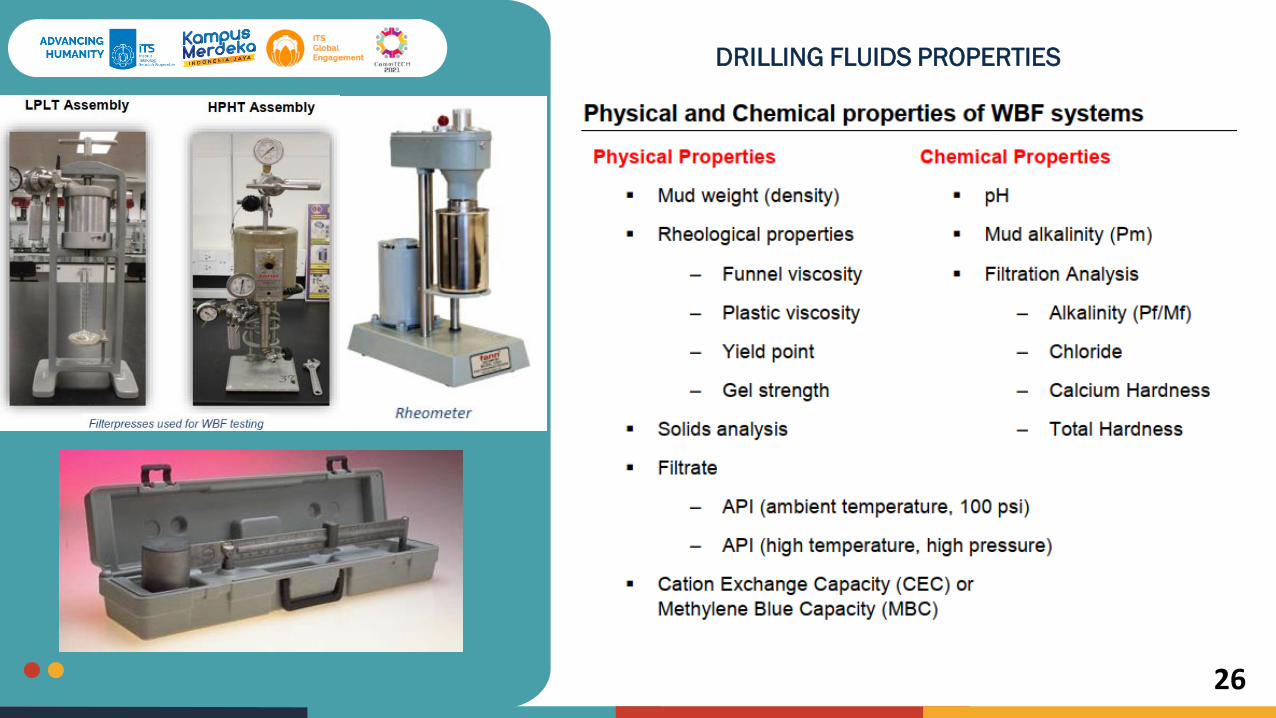
DRILLING FLUIDS PROPERTIES

ITS
Global
Engagement
27
POTENTIAL DRILLING HAZARD RELATED TO DRILLING
FLUIDS
Lost Circulation

ITS
Global
Engagement
28
POTENTIAL DRILLING HAZARD RELATED TO DRILLING
FLUIDS
Lost Circulation - Solution
Cement plug Blind drilling using aerated mud
ITS
Global
Engagement
29
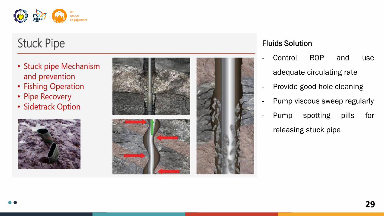
Fluids Solution
- Control ROP and use
adequate circulating rate
- Provide good hole cleaning
- Pump viscous sweep regularly
- Pump spotting pills for
releasing stuck pipe
ITS
Global
Engagement
30
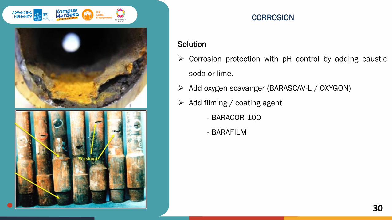
CORROSION
Solution
Corrosion protection with pH control by adding caustic
soda or lime.
Add oxygen scavanger (BARASCAV-L / OXYGON)
Add filming / coating agent
- BARACOR 100
- BARAFILM

ITS
Global
Engagement
31
ACID GAS CONTAMINATION
Carbon dioxide (CO2) and hydrogen sulfide
(H2S) are often found as components of natural
gas.

ITS
Global
Engagement
32

ITS
Global
Engagement
33
Terima KasihThank you