Geothermal Drilling Best Practices: The Geothermal translation of ...
12
Vollmar, D. Wittig, V. and Bracke, R.: Geothermal Drilling Best Practices, The Geothermal translation of conventional drilling recommendations - main potential challenges IGA Academy Report International Finance Corporation IFC Geothermal Drilling Best Practices: The Geothermal translation of conventional drilling recommendations - main potential challenges D. Vollmar, V. Wittig, R. Bracke GZB - International Geothermal Centre, Bochum / Germany Abstract: The main difference between conventional hydrocarbon and geothermal drilling is the characteristics of the source rock. The production zone of geothermal drilling is typically not a low-consolidated sedimentary rock as in conventional drilling for hydrocarbon reservoirs. Common rock types for hydro- and petrothermal reservoirs are hard volcanic and intrusive rocks or rigid sedimentary rocks, e.g. limestones or quartzitic sandstones. They are most- ly good heat conductors and have high primary or enhanced permeabilities on fractured zones. The formation fluids often contain highly corrosive brines. Compared to relatively soft sedimentary rocks, geothermal formations are by definition hot, abrasive, highly fractured and have a comparable high compressive strength. 1 Introduction The general objective of drilling is to generate a well in the most secure way by following standard proce- dures in order to recover economically the resource out of the reservoir. For geothermal drilling the re- source is stored as heat in hot fractured intrusive, volcanic or hard sedimentary rocks. Commonly conventional drilling procedures for geo- thermal wells are applied as long as the drilling pro- cess has not yet entered the production zone. For drilling into and through crystalline petrothermal reservoirs it is recommended to use adapted applica- tions for geothermal well drilling. Most petrothermal systems contain dissolved carbon dioxide and hydrogen sulfide gases, which particular limit the life of the drilling equipment. Higher strength steels are not suited to prevent sulfide stress cracking. The dual porosity of hydrothermal reservoirs com- promises wellbore stability and control. Circulation losses are able to lead to blow outs and break outs, which may result in stuck pipe incidents. Lost circu- lation treatments represent possibly 15% of total well cost [Finger & Blankenship, 2010]. A drilling plan should list and define all activities required to securely complete the well including all its related work and cost. It is imperative for the op- erator to take good care of communication and im- plementation of his booked services. These include planning and review of the execution plan. The overall objective of the geothermal drilling con- tractor is to reduce drilling cost. The better the for- mation properties are known via geoscientific sur- veys, the larger are the possible savings from the drilling program. Even old drilling reports from neighboring wells can give valuable information about formation behavior while drilling through the rock. In order to reduce possible risks, it is essential to generate a large data pool. All engineering as- sumption and, respectively, the whole drilling pro- gram, rely on these data and surveys. 2 Geothermal Drilling The main focus for geothermal drilling is the higher costs compared to conventional hydrocarbon drilling. In geothermal drilling there are three main well cost drivers. The biggest one is the technical challenge due to in-situ hardrock parameters. The 2 nd driver is the sufficient (larger) borehole diameter to guarantee the needed mass flow. The larger the wellbore diame- ter, the slower are drilling and completion time. The 3 rd and smallest driver, but with the biggest possible savings, is its uniqueness.
Transcript of Geothermal Drilling Best Practices: The Geothermal translation of ...
Vollmar, D. Wittig, V. and Bracke, R.: Geothermal Drilling Best Practices, The Geothermal translation of conventional drilling recommendations - main potential challenges
IGA Academy Report International Finance Corporation IFC
Geothermal Drilling Best Practices: The Geothermal translation of conventional drilling recommendations - main potential challenges
D. Vollmar, V. Wittig, R. Bracke
GZB - International Geothermal Centre, Bochum / Germany
Abstract: The main difference between conventional hydrocarbon and geothermal drilling is the characteristics of the source rock. The production zone of geothermal drilling is typically not a low-consolidated sedimentary rock as in conventional drilling for hydrocarbon reservoirs. Common rock types for hydro- and petrothermal reservoirs are hard volcanic and intrusive rocks or rigid sedimentary rocks, e.g. limestones or quartzitic sandstones. They are most-ly good heat conductors and have high primary or enhanced permeabilities on fractured zones. The formation fluids often contain highly corrosive brines. Compared to relatively soft sedimentary rocks, geothermal formations are by definition hot, abrasive, highly fractured and have a comparable high compressive strength.
1 Introduction The general objective of drilling is to generate a well in the most secure way by following standard proce-dures in order to recover economically the resource out of the reservoir. For geothermal drilling the re-source is stored as heat in hot fractured intrusive, volcanic or hard sedimentary rocks.
Commonly conventional drilling procedures for geo-thermal wells are applied as long as the drilling pro-cess has not yet entered the production zone. For drilling into and through crystalline petrothermal reservoirs it is recommended to use adapted applica-tions for geothermal well drilling.
Most petrothermal systems contain dissolved carbon dioxide and hydrogen sulfide gases, which particular limit the life of the drilling equipment. Higher strength steels are not suited to prevent sulfide stress cracking.
The dual porosity of hydrothermal reservoirs com-promises wellbore stability and control. Circulation losses are able to lead to blow outs and break outs, which may result in stuck pipe incidents. Lost circu-lation treatments represent possibly 15% of total well cost [Finger & Blankenship, 2010].
A drilling plan should list and define all activities required to securely complete the well including all its related work and cost. It is imperative for the op-
erator to take good care of communication and im-plementation of his booked services. These include planning and review of the execution plan.
The overall objective of the geothermal drilling con-tractor is to reduce drilling cost. The better the for-mation properties are known via geoscientific sur-veys, the larger are the possible savings from the drilling program. Even old drilling reports from neighboring wells can give valuable information about formation behavior while drilling through the rock. In order to reduce possible risks, it is essential to generate a large data pool. All engineering as-sumption and, respectively, the whole drilling pro-gram, rely on these data and surveys.
2 Geothermal Drilling The main focus for geothermal drilling is the higher costs compared to conventional hydrocarbon drilling. In geothermal drilling there are three main well cost drivers. The biggest one is the technical challenge due to in-situ hardrock parameters. The 2nd driver is the sufficient (larger) borehole diameter to guarantee the needed mass flow. The larger the wellbore diame-ter, the slower are drilling and completion time. The 3rd and smallest driver, but with the biggest possible savings, is its uniqueness.
Vollmar, D., Wittig, V. and Bracke, R: Geothermal Drilling Best Practices, The Geothermal translation of conventional drilling recommendations - main potential challenges.
IGA Academy Report 001/13 International Finance Corporation IFC
2
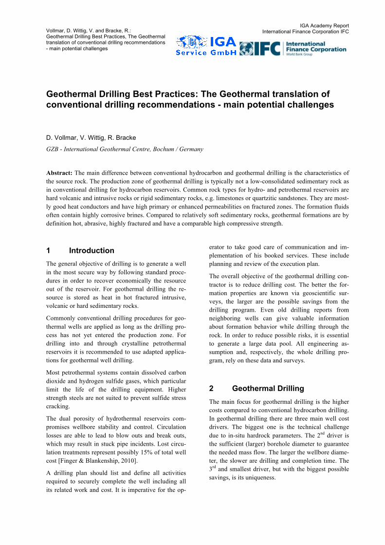
Well design is a bottom-up process. Location of the production zone and the necessary flow to extract sufficient energy determines the overall well geome-try such as pathways and diameter. The well’s profile above the production zone is then set by iteration of the larger casing strings required by geological con-siderations and / or drilling. Due to large diameters in geothermal wells the percentage of cementing and casing procedures are relatively high compared to the overall cost. The ability to reduce just one string of casing may have a major impact to reduce cost.
Figure 1 shows a typical casing profile for a geo-thermal well, which consists of an open hole comple-tion. The casing depth depends on trouble zones, which need to be completed in order to continue drilling. Above the production zone the borehole diameter is being increased from section to section like a telescope in order to run the next bit size through the cemented casing to proceed drilling with a smaller gauge bit. Due to the liner completion it is possible to reduce the cost for steal and cement. However, the added cost from the larger diameter compared to conventional drilling still remains.
13 3/8"
20"
28"Stand pipe
Surface Casing
Liner
Open Hole
Liner
10 3/4"
9 1/2"
Figure 1: Geothermal well profile with an open hole completion
The majority of experienced geothermal operators prefer an open hole completion due to supplementary costs associated with this completion. The high(er) temperatures potentially make cementing and perfo-
rating challenging. On the other hand, cased holes allow discrete zones to be fractured, isolate low tem-perature or thief zones, facilitate generation of multi-ple fracture systems and allow future remediation.
When drilling proceeds as expected, the drilling prob-lems are well known. However, as drilling is operated through fractured hot reservoirs, the severity of get-ting a blowout or even getting a stuck pipe is in-creased. For conventional wells this would be a de-pleted reservoir, which most likely would be liner drilled in underbalanced conditions in order to avoid high circulation losses and probability of blow outs. An option for the geothermal well would be an un-derbalanced Screen Liner Drilling Sequence instead of using conventional liners.
The most common solution for drilling through hard rock and petrothermal systems is the application of controlled pressure drilling equipment. There are three major types of controlled pressure drilling methods:
• Air drilling (AD)
• Managed pressure drilling (MPD)
• Underbalanced drilling (UBD)
AD is geared toward optimizing the rate of penetra-tion (ROP), MPD minimizes rig non-performance time and UBD increases productivity and reduces reservoir damage. For the case of drilling through a non-fractured source rock, it is not necessary to drill pressure controlled before stimulating the pay zone.
Short bit life, due to of hard, fractured, abrasive and high temperature rock conditions increases tripping time dramatically. There are savings possible up to 5 % of the total well cost by only doubling the bit life. Low penetration rates are common in hard, abra-sive rock conditions. By achieving penetration rates on a routine basis not lower than 30 ft/hr cuts the overall well cost up to 15 % [Finger and Blankenship, 2010].
2.1 Drilling Parameters
There are three drilling parameters, which guarantee, in the right combination, an optimum rate of penetra-tion. The most important parameter is the flow rate of the drilling mud which serves as a transportation vehicle for the cuttings and cleaning of the bit. The efficient flow rate depends on the borehole diameter, mud and rock parameters. The drilling mud is carried
Vollmar, D., Wittig, V. and Bracke, R: Geothermal Drilling Best Practices, The Geothermal translation of conventional drilling recommendations - main potential challenges.
IGA Academy Report 001/13 International Finance Corporation IFC
3
via the inner cross section of the drill string to the bit. The next parameter is weight on bit (WOB). To pro-duce the cuttings, the compressive strength of the formation has to be overcome, which is created by 2/3rd of the drill collars, called the WOB. A shift of the neutral point towards the drill string reduces dra-matically the ability to steer the tool for directional control. The rotation of the bit assures a smooth cut-ting surface. The teeth of the bit are walking along the borehole axis and are cutting the whole wellbore bottom hole profile. The rotation additionally reduces the drag and torque of the drilling equipment.
2.2 Drilling Tools
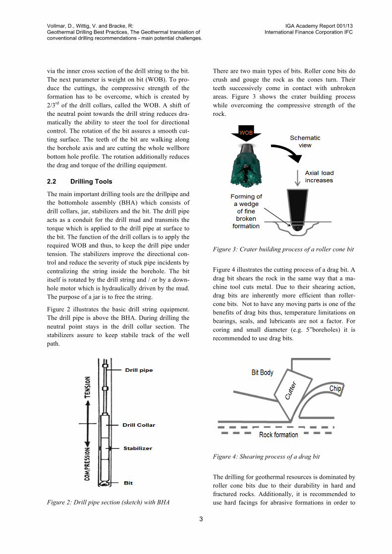
The main important drilling tools are the drillpipe and the bottomhole assembly (BHA) which consists of drill collars, jar, stabilizers and the bit. The drill pipe acts as a conduit for the drill mud and transmits the torque which is applied to the drill pipe at surface to the bit. The function of the drill collars is to apply the required WOB and thus, to keep the drill pipe under tension. The stabilizers improve the directional con-trol and reduce the severity of stuck pipe incidents by centralizing the string inside the borehole. The bit itself is rotated by the drill string and / or by a down-hole motor which is hydraulically driven by the mud. The purpose of a jar is to free the string.
Figure 2 illustrates the basic drill string equipment. The drill pipe is above the BHA. During drilling the neutral point stays in the drill collar section. The stabilizers assure to keep stabile track of the well path.
Figure 2: Drill pipe section (sketch) with BHA
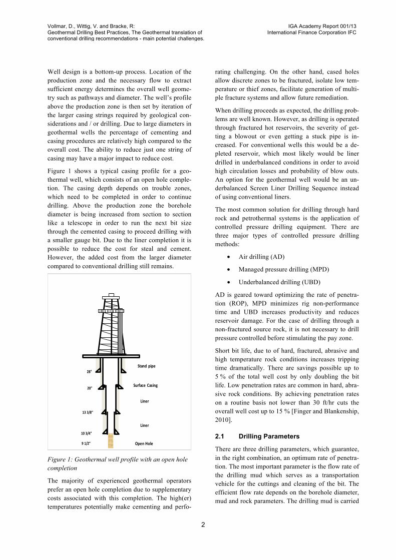
There are two main types of bits. Roller cone bits do crush and gouge the rock as the cones turn. Their teeth successively come in contact with unbroken areas. Figure 3 shows the crater building process while overcoming the compressive strength of the rock.
Figure 3: Crater building process of a roller cone bit
Figure 4 illustrates the cutting process of a drag bit. A drag bit shears the rock in the same way that a ma-chine tool cuts metal. Due to their shearing action, drag bits are inherently more efficient than roller-cone bits. Not to have any moving parts is one of the benefits of drag bits thus, temperature limitations on bearings, seals, and lubricants are not a factor. For coring and small diameter (e.g. 5”boreholes) it is recommended to use drag bits.
Figure 4: Shearing process of a drag bit
The drilling for geothermal resources is dominated by roller cone bits due to their durability in hard and fractured rocks. Additionally, it is recommended to use hard facings for abrasive formations in order to
Vollmar, D., Wittig, V. and Bracke, R: Geothermal Drilling Best Practices, The Geothermal translation of conventional drilling recommendations - main potential challenges.
IGA Academy Report 001/13 International Finance Corporation IFC
4
keep the gauge of the hole and to reduce wear of the bit. For aerated mud systems drilling with roller cone bits is not recommended due to seal and bearing failures as the down hole temperature increases.
2.3 Drill Rig
Rig specifications are intended to ensure proper se-lection of the rig, which is satisfactory for the well needed to be drilled. These minimum requirements evolve from the well plan requirements and are the basis for the contract bid request. The API bulletin D10 “Procedure for selecting rotary drilling equip-ment” contains forms that help to identify the best suited rig capabilities.
To ensure maximum operating efficiency, the rig has to be properly sized for the well. Usually, the rig is specified on the depth range and the hoisting horse-power. This oversimplification helps to identify the possible rigs and serves for further comparison. Less rig power means a lower price for the bid, but if the lower powered rig does not meet the specifications, it will incur higher overall costs for the contractor. On the other hand an oversized rig will incur higher costs as necessary.
The rig requirements also change with the well diam-eter and depth. As drilling rates are decreasing, the wellbore size becomes smaller or the bit runs de-crease as less rotary torque and pump power is need-ed. The focal point at these conditions is on hoisting power to reduce the overall tripping time.
Mud pumps should have enough volumetric capacity to create sufficient velocity in the annulus to lift the cuttings. Their pressure capacity must provide the desired pressure drop through the bit jets, compensate all pipe pressure losses and potentially drive a mud motor if that is planned or a likely contingency.
The load handling capability of the derrick and the top drive is of critical concern when casing drilling or managed pressure drilling is applied. Thus, running the casing deep limits the static depth ranging of the derrick. For managed pressure drilling, the height of the substructure must be sufficient enough to place a tall BOP stack.
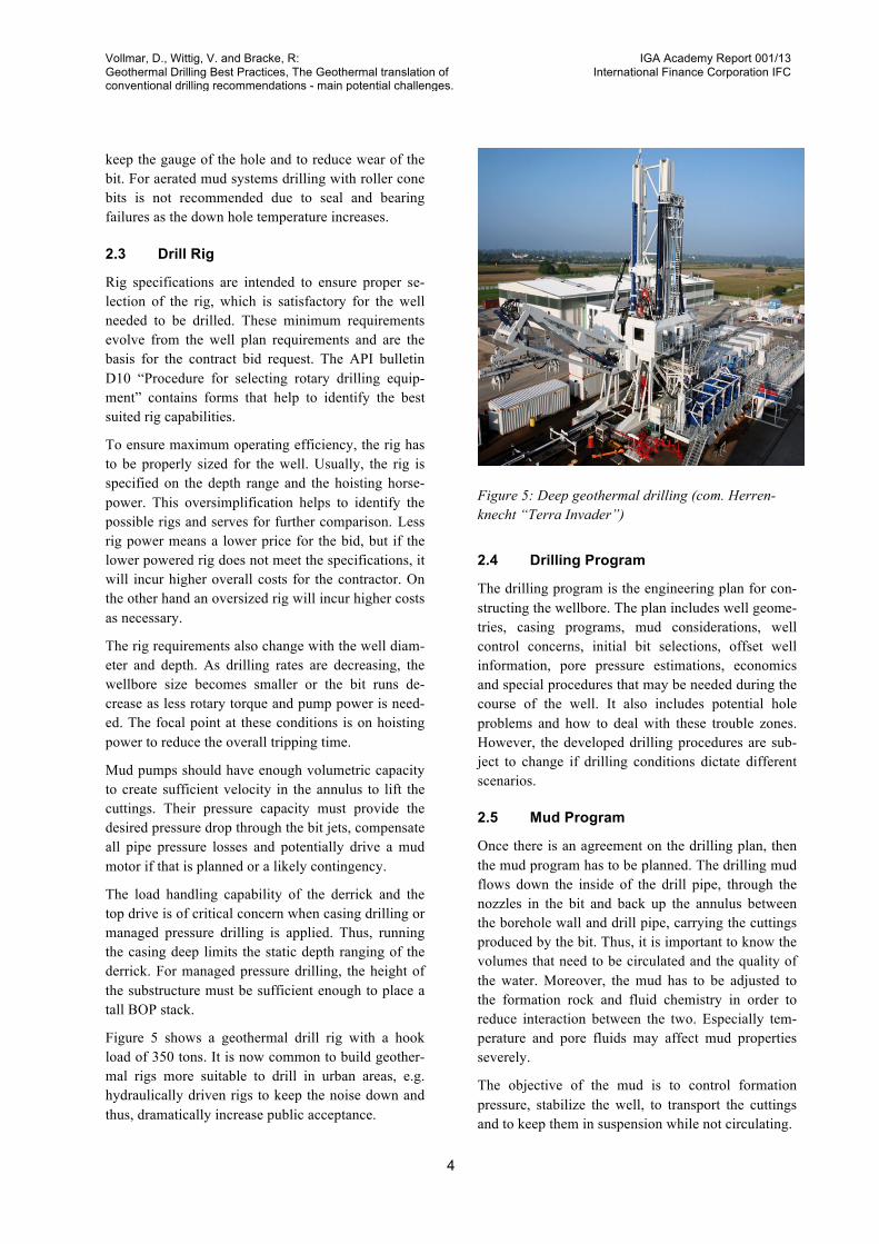
Figure 5 shows a geothermal drill rig with a hook load of 350 tons. It is now common to build geother-mal rigs more suitable to drill in urban areas, e.g. hydraulically driven rigs to keep the noise down and thus, dramatically increase public acceptance.
Figure 5: Deep geothermal drilling (com. Herren-knecht “Terra Invader”)
2.4 Drilling Program
The drilling program is the engineering plan for con-structing the wellbore. The plan includes well geome-tries, casing programs, mud considerations, well control concerns, initial bit selections, offset well information, pore pressure estimations, economics and special procedures that may be needed during the course of the well. It also includes potential hole problems and how to deal with these trouble zones. However, the developed drilling procedures are sub-ject to change if drilling conditions dictate different scenarios.
2.5 Mud Program
Once there is an agreement on the drilling plan, then the mud program has to be planned. The drilling mud flows down the inside of the drill pipe, through the nozzles in the bit and back up the annulus between the borehole wall and drill pipe, carrying the cuttings produced by the bit. Thus, it is important to know the volumes that need to be circulated and the quality of the water. Moreover, the mud has to be adjusted to the formation rock and fluid chemistry in order to reduce interaction between the two. Especially tem-perature and pore fluids may affect mud properties severely.
The objective of the mud is to control formation pressure, stabilize the well, to transport the cuttings and to keep them in suspension while not circulating.
Vollmar, D., Wittig, V. and Bracke, R: Geothermal Drilling Best Practices, The Geothermal translation of conventional drilling recommendations - main potential challenges.
IGA Academy Report 001/13 International Finance Corporation IFC
5
In order to control the formation pressure and stabi-lize the well, the mud pressure must be controlled in a small window between the pore pressure and the formation pressure / fracture gradient of the rock. The mud pressure is dictated by the density of the cutting loaded mud with considerations of additional friction losses and the True Vertical Depth (TVD).
Another important mud parameter is the viscosity, which increases the sweep efficiency of the cutting transport. Increasing viscosity means higher pressure loss due to friction effects. Simultaneously, this af-fects the ECD (Equivalent Circulating Density) and might cause tensile stress cracks along the highest horizontal principal stress direction.
The majority of geothermal wells have so far been drilled with fairly simple mixtures of fresh water and bentonite clay, possibly with some polymers. Aerated mud systems are preferred where lost circulation is a significant problem. In aerated mud systems, usually air - but sometimes nitrogen, if corrosion is serious - is injected into the liquid in order to reduce the densi-ty. Drilling with air only is also relatively common in Geysers and has some advantages in drilling perfor-mance because ROP is usually higher than with mud or aerated mud.
Especially while drilling the drill mud has to be mon-itored and maintained carefully in order to ensure the predesigned physico-chemical mud parameters or to change them if drilling conditions dictate different scenarios.
2.6 Casing Design
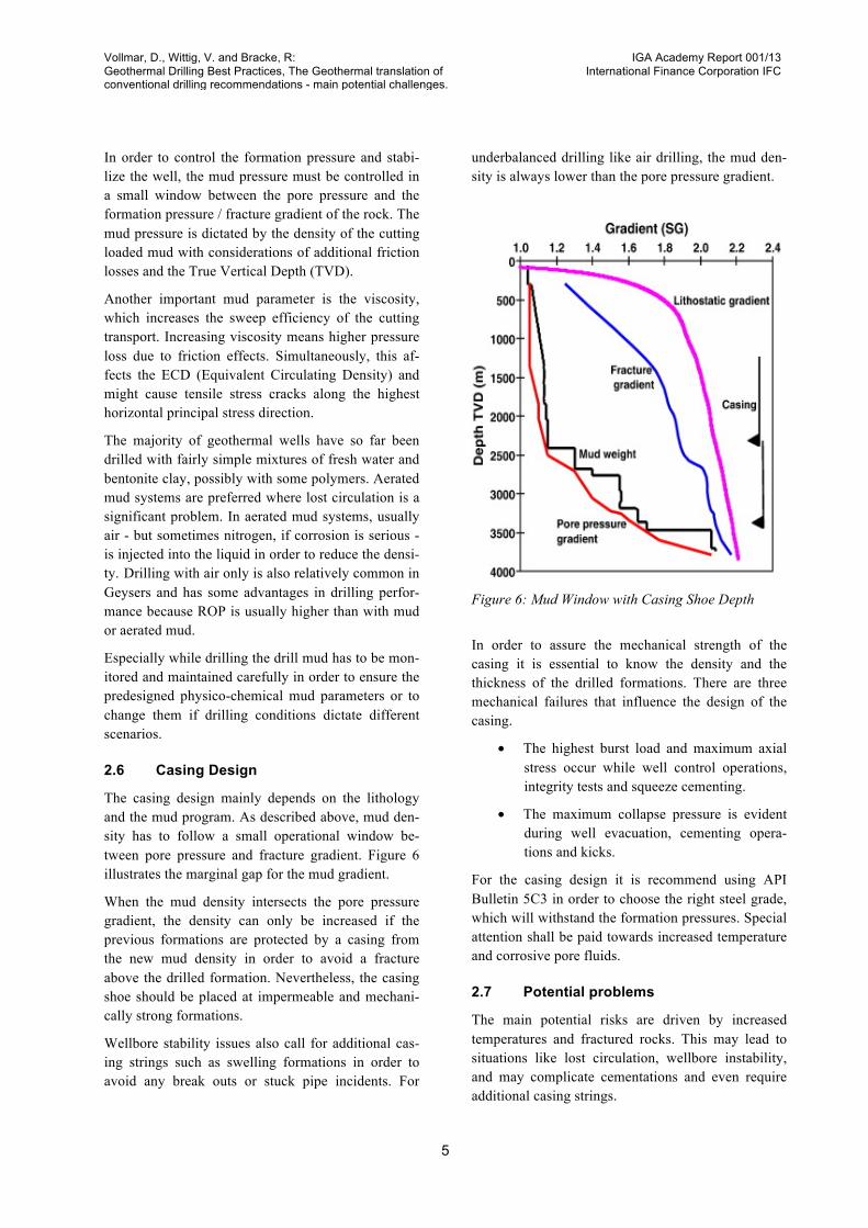
The casing design mainly depends on the lithology and the mud program. As described above, mud den-sity has to follow a small operational window be-tween pore pressure and fracture gradient. Figure 6 illustrates the marginal gap for the mud gradient.
When the mud density intersects the pore pressure gradient, the density can only be increased if the previous formations are protected by a casing from the new mud density in order to avoid a fracture above the drilled formation. Nevertheless, the casing shoe should be placed at impermeable and mechani-cally strong formations.
Wellbore stability issues also call for additional cas-ing strings such as swelling formations in order to avoid any break outs or stuck pipe incidents. For
underbalanced drilling like air drilling, the mud den-sity is always lower than the pore pressure gradient.
Figure 6: Mud Window with Casing Shoe Depth
In order to assure the mechanical strength of the casing it is essential to know the density and the thickness of the drilled formations. There are three mechanical failures that influence the design of the casing.
• The highest burst load and maximum axial stress occur while well control operations, integrity tests and squeeze cementing.
• The maximum collapse pressure is evident during well evacuation, cementing opera-tions and kicks.
For the casing design it is recommend using API Bulletin 5C3 in order to choose the right steel grade, which will withstand the formation pressures. Special attention shall be paid towards increased temperature and corrosive pore fluids.
2.7 Potential problems
The main potential risks are driven by increased temperatures and fractured rocks. This may lead to situations like lost circulation, wellbore instability, and may complicate cementations and even require additional casing strings.
Vollmar, D., Wittig, V. and Bracke, R: Geothermal Drilling Best Practices, The Geothermal translation of conventional drilling recommendations - main potential challenges.
IGA Academy Report 001/13 International Finance Corporation IFC
6
2.7.1 High Temperature The increased temperature of geothermal reservoirs is transferred through the whole steel drill pipe, which has a big effect on the downhole equipment due to the bath in hot fluid. The following problems occur through high temperatures:
• Elastomer components (seals, downhole mo-tor stators, bridge plugs) are challenged.
• Expensive and delicate electronic steering and logging tools can be damaged or de-stroyed.
• Corrosion rates increase and the drilling flu-id itself may be degraded.
These problems can be solved by using an isolated drill pipe (IDP) such that the drilling fluid reaches the bottom of the hole at a much lower temperature. Mud cooling is sometimes an option to reduce the tem-perature profile of the mud system.
2.7.2 Lost circulation Another main problem encountered for geothermal drilling is lost circulation. Losses of drilling fluids into the pores or into existing fractures of the for-mation result into wellbore instability or wellbore control problems such as a blowout. Around 10% of total cost of a geothermal project can be attributed to lost circulation [Finger and Blankenship, 2010]. The following problems occur through lost circulation:
• Drilling fluid is expensive and losing it to the formation instead of re-circulating it is rather costly.
• When the drilling fluid fails to clean the hole and doesn´t return cuttings to the surface due to the missing height, the cuttings may fall back on the bottom hole assembly and bury the drill bit and BHA.
• The reduced hydrostatic head is not able to provide efficient force to keep the formation fluids in the pores and may lead to an un-controlled influx of pore fluids.
Tackling lost circulation can be approached in differ-ent ways and depends on the boundary conditions such as the lithology. The most common ways to combat these losses are as follows.
• Drill ahead with lost circulation. Do not stop pumping due to the risk of stuck pipe inci-dents.
• Drill with a lightweight drilling fluid that will have a static head less than the pore pressure in the formation
• Mix the drilling fluid with fibrous material or particles that will plug the loss apertures / pathways into the formation
• When the wellbore is completely clean it can be considered to pause the drilling process and try to seal the loss zones with some ma-terial that can be drilled out as the borehole advances.
The fractures, which are too large to be plugged by lost circulation material (LCM), can be sealed by pulling the drill string out of the hole and injecting some viscous material, such as polymers that will enter the fractures, solidify to seal them. Afterwards, it should be possible to remove the residue by re-sumption of drilling. In geothermal drilling, lost cir-culation treatment practice is to lower the end of an open end drill pipe (OEDP) near the assumed loss zone and to pump a given quantity of cement (usually 10 m³) into the wellbore.
2.7.3 Wellbore instability Wellbore instability results from a number of reasons, which can cause widely varying kinds of problems.
• Mechanically unstable wellbore due to the pre-fractured rock or due to degradation of the wall from the invasion of liquid from the drilling fluids. The wellbore wall - especial-ly in formations with significant clay con-tents above the hard rock production zone - may become weakened by adsorption of wa-ter into the clay of the wellbore rock.
• Unconsolidated formations from the over-burden can aggravate hole cleaning prob-lems because it may fall in around the drill pipe to stick it, plus it can wash out to a very large diameter. Large washouts not only complicate the cementing, but also lower fluid velocity in the larger diameter, which leads to a reduced carrying capacity for cut-tings.

Vollmar, D., Wittig, V. and Bracke, R: Geothermal Drilling Best Practices, The Geothermal translation of conventional drilling recommendations - main potential challenges.
IGA Academy Report 001/13 International Finance Corporation IFC
7
• Swelling or squeezing clays may minimize the borehole diameter to an extent that will either get the pipe stuck or prevent running casing.
• Differential stresses may cause the borehole to become unstable. This is a particular problem whenever boreholes are deviated away from vertical.
Each of these problems will make it difficult to clean the hole of cuttings and will ultimately make cement-ing the casing or liner in place very difficult.
A solution to advance drilling by slowing the adsorp-tion process of water into the clay and to reduce the swelling is to use CMC, which works inhibitive for clays. In case of swelling clays it is also common to enlarge the clay section with a bigger diameter to prevent sticking of the casing while running in hole.
The problem of unconsolidated formations can be mitigated by using highly viscous drilling muds, which can be composed from bentonite mixtures. In order to prevent wellbore instability due to high dif-ferential stresses it is necessary to know the values of the minimum and maximum horizontal principal stresses and their directions.
2.7.4 Cementation and Casing Since geothermal wells are most likely cemented completely to surface, there is often a problem get-ting a good cement job done where the formations have shown either low strength or lost circulation. The reason is the higher density of the cement - and thus higher hydrostatic head - compared to drilling fluids. Additionally, it is crucial that no water is trapped between the cement and the casing to avoid a collapse of the casing as the wellbore goes through its temperature cycles.
In low pressure and low strength zones sometimes cementation methods have successfully been used by applying very light weight cements (less than 1.5 g/cm3). Lost circulation during cementing often re-sults in bad cement jobs where the cement either does not reach the surface or falls back after reaching the surface. If the cement is not very far from the surface, it can be repaired by a top job, where the cement is placed into the annulus between casings via small diameter tubing, called tremie pipe. However, this is usually only effective down to the first centralizer, as the tremie pipe may not pass that centralizer. For this
reason, the top two joints of casing are usually left without a centralizer. If the tremie pipe does not reach the top of the cement, there is too much risk of trapping water and collapsing the casing, so this method should not be used.
If a Blow-out-Preventer (BOP) is placed on the well-head a back flush and back fill process can be used. The BOP can be closed immediately after the cemen-tation and the annular space between the casings is flushed with water (usually 1.5 times the annular volume). After the remaining cement has been set, an injection rate can be established down the annulus (probably fracturing away the fluid), subsequently followed by cement to fill the annulus. This may require hesitation squeezing or a second stage of flush and backfill in extreme cases.
All wells are designed to be completed with a given size production interval. But the casing program is aimed at minimizing the total amount of casing be-cause it is very expensive: casing and cement can account for 30 to 35 % of total well cost. This is particularly important in geothermal wells, where the economically necessary mass flow rates require larg-er diameter production intervals compared to typical oil and gas wells.
If unexpected problems require an extra string of casing, the production casing will become smaller than planned, thus, reducing the potential flow rate and adding costs. To avoid such a situation the casing program is often designed with the upper casing one size larger than required - in case a contingent string is needed.
In reservoirs of high enthalpy geothermal wells have self-powered production through flushing in the wellbore. The boiling process lightens the fluid col-umn and drive the fluid up the well. This means that a reduction in diameter can result in much less produc-tion than planned for. There are no simple or cheap solutions to this problem. The expandable casing solution is routinely used in oil and gas for these situations (as discussed in Section 10, emerging tech-nologies), but it is neither simple nor cheap.
2.8 Well control
Well control is the prevention of fluid influx of the formation into the borehole. As long as the hydrostat-ic head of the drilling mud is below pore pressure, the pore fluid will flow into the wellbore.
Vollmar, D., Wittig, V. and Bracke, R: Geothermal Drilling Best Practices, The Geothermal translation of conventional drilling recommendations - main potential challenges.
IGA Academy Report 001/13 International Finance Corporation IFC
8
There are two situations that might cause a loss of circulation.
• Circulating hot fluids from deeper depths to the surface, resulting in the fluids flashing to steam, which causes a loss in hydrostatic pressure, and a further flashing or boil down effect.
• Lost circulation causes the fluid level, and thus the pressure, in the wellbore to sudden-ly fall far enough for the same thing to hap-pen.
For the case of a liquid influx, it is recommended to shut in and kill the wellbore using the drillers meth-od. This is important especially for H2S loaded liq-uids, where the concentrations might be lethal.
It is advised to kill the wellbore at hot fractured zones with cold drilling mud in order to prevent the produc-tion of lethal gas to the surface, which breach to the surface or boil down the equipment. Every kick should be treated as a gas kick until confirmed oth-erwise. Unfortunately BOP are equipped with the normal temperature rubbers, which have a working tempera-ture limit of 121°C, because of the high cost and limited availability of high temperature BOP rubbers. Even equipping the BOP’s with high temperature rubbers may not provide adequate safety, as they have a working temperature limit of 177°C.
As pressures increase when circulating out a high temperature kick, even these higher temperatures may be exceeded. For that reason, a cooling line should be connected below the pipe rams to pump cool water down through the inside of the BOP and out the choke line during a kill operation, if the tem-perature might exceed the working temperature of the BOP.
Unexpected steam or gas flow can be caused by drill-ing into a formation that is at much higher tempera-ture or much higher pressure than predicted. Alterna-tively by sudden, major lost circulation, which can drop the drilling fluid level to the point that its static head no longer exceeds the saturation pressure at the formation’s temperature. Hence, either the drilling fluid or formation fluids flash into steam. Unexpected steam flow in a permeable formation that is not com-pletely sealed by casing is particularly dangerous: because steam can begin to flow up the outside of the previous casing string, called “underground blow
out”. This will eventually destroy the casing’s integri-ty and often causes loss of the drill rig.
For geothermal reservoirs with a dry (or superheated) steam resource, the production interval is often drilled with air to avoid formation damage and plug-ging. The drilling returns include produced steam from the reservoir. The top of the BOP contains a “rotating head” that seals around the drill pipe, while allowing it to rotate and move downward. The gase-ous returns are sent through a manifold called a “ban-jo box” which is located below the BOP but above a hydraulically actuated wellhead valve. From here it moves on through the “blooie line” which exhausts a distance away from the drill rig and where the returns receive chemical treatment for H2S abatement.
Since the steam is exhausted to the atmosphere the temperature only reaches the boiling point for steam (100°C) or slightly more if it contains some super-heat. Consequently, the temperature does not exceed the 121°C working limit for normal BOP rubbers. This is very similar to the technique called “managed pressure drilling” in oil and gas reservoirs, where it has been discovered that productivity is much im-proved if drilling fluid has not been forced into the formation by excessive downhole pressure.
2.9 Advanced drilling technologies
Avoiding risks driven by uncertainties becomes a challenge for exploitation of geothermal resources. A consideration of advanced drilling technologies might mitigate the prospecting risk by reducing drilling cost.
2.9.1 Casing while drilling
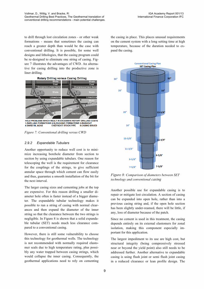
One option to reduce lost circulation problems and to gain casing depth in order to reduce the overall well costs could be Casing While Drilling (CWD). CWD systems can continue drilling when lost circulation is encountered. This is accomplished by using the cas-ing as the drill pipe, rotating to turn a bit and advanc-ing with the hole as it gets deeper, so that it is already in place when the hole reaches desired depth.
The rock cuttings tend to be washed into the fractures or permeable zones, acting effectively as lost circula-tion material. The relatively narrow annulus outside of the casing (= drill pipe) also means that fluid flow rates may be lower than normal with conventional drilling in the same size hole. However, the required torque of the rig / top drive will be higher. The ability
Vollmar, D., Wittig, V. and Bracke, R: Geothermal Drilling Best Practices, The Geothermal translation of conventional drilling recommendations - main potential challenges.
IGA Academy Report 001/13 International Finance Corporation IFC
9
to drill through lost circulation zones - or other weak formations - means that sometimes the casing can reach a greater depth than would be the case with conventional drilling. It is possible, for some well designs and lithologies, that the casing program could be re-designed to eliminate one string of casing. Fig-ure 7 illustrates the advantages of CWD. An alterna-tive for casing drilling into the productive zone is liner drilling.
Figure 7: Conventional drilling versus CWD
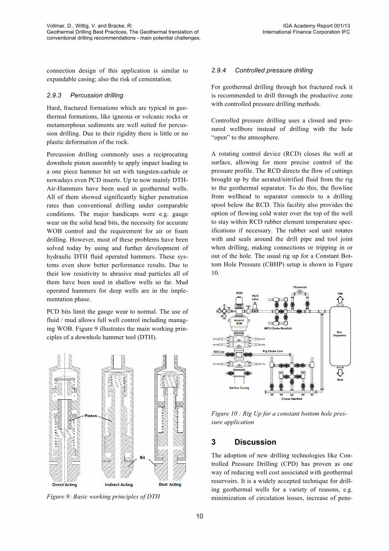
2.9.2 Expandable Tubulars Another opportunity to reduce well cost is to mini-mize increasing borehole diameter from section to section by using expandable tubulars. One reason for telescoping the well is the requirement for clearance for the couplings of the strings, to give sufficient annular space through which cement can flow easily and thus, guarantee a smooth installation of the bit for the next interval.
The larger casing sizes and cementing jobs at the top are expensive. For this reason drilling a smaller di-ameter hole often is faster instead of a bigger diame-ter. The expandable tubular technology makes it possible to run a string of casing with normal clear-ances and then expand the diameter of the inner string so that the clearance between the two strings is negligible. In Figure 8 is shown that a solid expanda-ble tubular (SET) needs much less clearance com-pared to a conventional casing.
However, there is still some vulnerability to choose this technology for geothermal wells. The technology is not recommended with normally required elasto-mer seals due to high temperature rating, plus possi-bly any water trapped between casing strings, which would collapse the inner casing. Consequently, the geothermal applications need to rely on cementing
the casing in place. This places unusual requirements on the cement system with a long setting time at high temperature, because of the duration needed to ex-pand the casing.
Figure 8: Comparison of diameters between SET technology and conventional casing
Another possible use for expandable casing is to repair or mitigate lost circulation. A section of casing can be expanded into open hole, rather than into a previous casing string and, if the open hole section has been slightly under-reamed, there will be little, if any, loss of diameter because of the patch.
Since no cement is used in this treatment, the casing depends entirely on its external elastomers for zonal isolation, making this component especially im-portant for this application.
The largest impediment to its use are high cost, but structural integrity (being compressively stressed near or beyond the yield point) also still needs to be addressed further. Another alternative to expandable casing is using flush joint or semi flush joint casing in a reduced clearance or lean profile design. The
Vollmar, D., Wittig, V. and Bracke, R: Geothermal Drilling Best Practices, The Geothermal translation of conventional drilling recommendations - main potential challenges.
IGA Academy Report 001/13 International Finance Corporation IFC
10
connection design of this application is similar to expandable casing; also the risk of cementation.
2.9.3 Percussion drilling Hard, fractured formations which are typical in geo-thermal formations, like igneous or volcanic rocks or metamorphous sediments are well suited for percus-sion drilling. Due to their rigidity there is little or no plastic deformation of the rock.
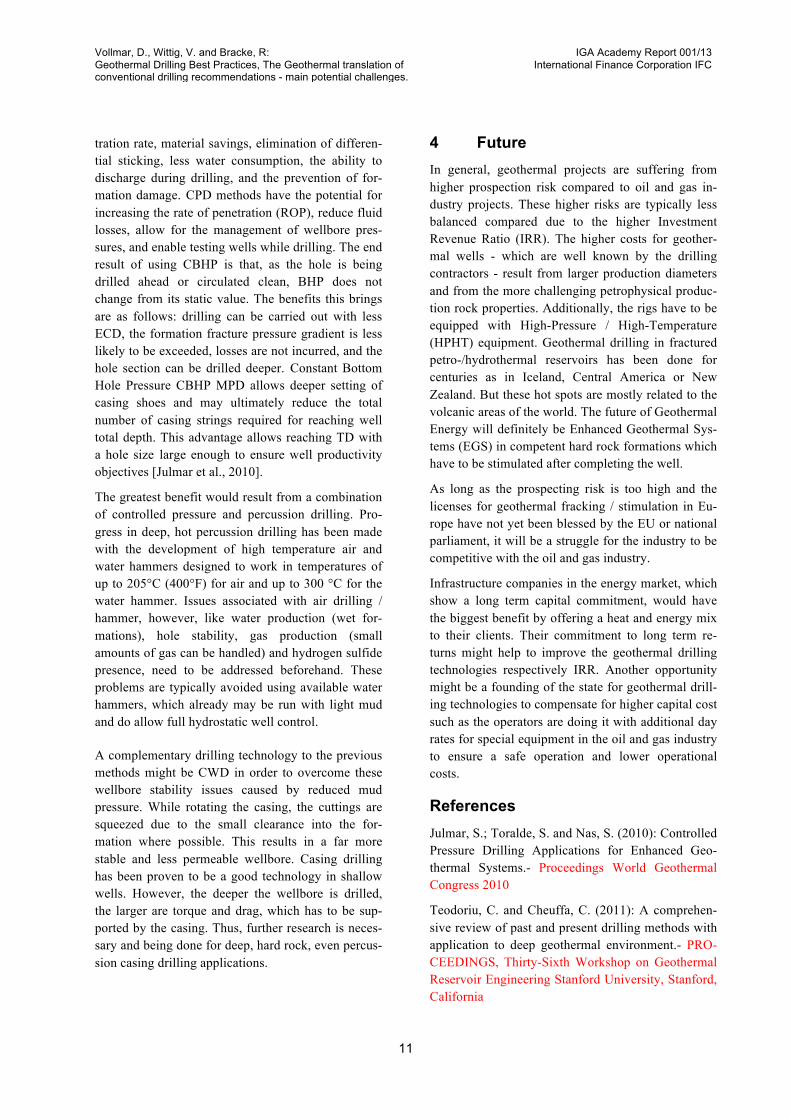
Percussion drilling commonly uses a reciprocating downhole piston assembly to apply impact loading to a one piece hammer bit set with tungsten-carbide or nowadays even PCD inserts. Up to now mainly DTH-Air-Hammers have been used in geothermal wells. All of them showed significantly higher penetration rates than conventional drilling under comparable conditions. The major handicaps were e.g. gauge wear on the solid head bits, the necessity for accurate WOB control and the requirement for air or foam drilling. However, most of these problems have been solved today by using and further development of hydraulic DTH fluid operated hammers. These sys-tems even show better performance results. Due to their low resistivity to abrasive mud particles all of them have been used in shallow wells so far. Mud operated hammers for deep wells are in the imple-mentation phase.
PCD bits limit the gauge wear to normal. The use of fluid / mud allows full well control including manag-ing WOB. Figure 9 illustrates the main working prin-ciples of a downhole hammer tool (DTH).
Figure 9: Basic working principles of DTH
2.9.4 Controlled pressure drilling
For geothermal drilling through hot fractured rock it is recommended to drill through the productive zone with controlled pressure drilling methods.
Controlled pressure drilling uses a closed and pres-sured wellbore instead of drilling with the hole “open” to the atmosphere.
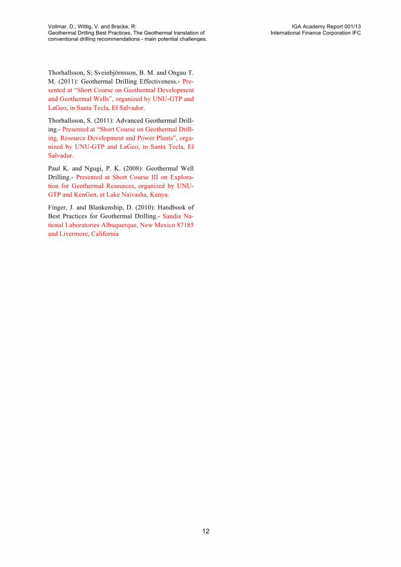
A rotating control device (RCD) closes the well at surface, allowing for more precise control of the pressure profile. The RCD directs the flow of cuttings brought up by the aerated/nitrified fluid from the rig to the geothermal separator. To do this, the flowline from wellhead to separator connects to a drilling spool below the RCD. This facility also provides the option of flowing cold water over the top of the well to stay within RCD rubber element temperature spec-ifications if necessary. The rubber seal unit rotates with and seals around the drill pipe and tool joint when drilling, making connections or tripping in or out of the hole. The usual rig up for a Constant Bot-tom Hole Pressure (CBHP) setup is shown in Figure 10.
Figure 10 : Rig Up for a constant bottom hole pres-sure application
3 Discussion The adoption of new drilling technologies like Con-trolled Pressure Drilling (CPD) has proven as one way of reducing well cost associated with geothermal reservoirs. It is a widely accepted technique for drill-ing geothermal wells for a variety of reasons, e.g. minimization of circulation losses, increase of pene-
Vollmar, D., Wittig, V. and Bracke, R: Geothermal Drilling Best Practices, The Geothermal translation of conventional drilling recommendations - main potential challenges.
IGA Academy Report 001/13 International Finance Corporation IFC
11
tration rate, material savings, elimination of differen-tial sticking, less water consumption, the ability to discharge during drilling, and the prevention of for-mation damage. CPD methods have the potential for increasing the rate of penetration (ROP), reduce fluid losses, allow for the management of wellbore pres-sures, and enable testing wells while drilling. The end result of using CBHP is that, as the hole is being drilled ahead or circulated clean, BHP does not change from its static value. The benefits this brings are as follows: drilling can be carried out with less ECD, the formation fracture pressure gradient is less likely to be exceeded, losses are not incurred, and the hole section can be drilled deeper. Constant Bottom Hole Pressure CBHP MPD allows deeper setting of casing shoes and may ultimately reduce the total number of casing strings required for reaching well total depth. This advantage allows reaching TD with a hole size large enough to ensure well productivity objectives [Julmar et al., 2010].
The greatest benefit would result from a combination of controlled pressure and percussion drilling. Pro-gress in deep, hot percussion drilling has been made with the development of high temperature air and water hammers designed to work in temperatures of up to 205°C (400°F) for air and up to 300 °C for the water hammer. Issues associated with air drilling / hammer, however, like water production (wet for-mations), hole stability, gas production (small amounts of gas can be handled) and hydrogen sulfide presence, need to be addressed beforehand. These problems are typically avoided using available water hammers, which already may be run with light mud and do allow full hydrostatic well control.
A complementary drilling technology to the previous methods might be CWD in order to overcome these wellbore stability issues caused by reduced mud pressure. While rotating the casing, the cuttings are squeezed due to the small clearance into the for-mation where possible. This results in a far more stable and less permeable wellbore. Casing drilling has been proven to be a good technology in shallow wells. However, the deeper the wellbore is drilled, the larger are torque and drag, which has to be sup-ported by the casing. Thus, further research is neces-sary and being done for deep, hard rock, even percus-sion casing drilling applications.
4 Future In general, geothermal projects are suffering from higher prospection risk compared to oil and gas in-dustry projects. These higher risks are typically less balanced compared due to the higher Investment Revenue Ratio (IRR). The higher costs for geother-mal wells - which are well known by the drilling contractors - result from larger production diameters and from the more challenging petrophysical produc-tion rock properties. Additionally, the rigs have to be equipped with High-Pressure / High-Temperature (HPHT) equipment. Geothermal drilling in fractured petro-/hydrothermal reservoirs has been done for centuries as in Iceland, Central America or New Zealand. But these hot spots are mostly related to the volcanic areas of the world. The future of Geothermal Energy will definitely be Enhanced Geothermal Sys-tems (EGS) in competent hard rock formations which have to be stimulated after completing the well.
As long as the prospecting risk is too high and the licenses for geothermal fracking / stimulation in Eu-rope have not yet been blessed by the EU or national parliament, it will be a struggle for the industry to be competitive with the oil and gas industry.
Infrastructure companies in the energy market, which show a long term capital commitment, would have the biggest benefit by offering a heat and energy mix to their clients. Their commitment to long term re-turns might help to improve the geothermal drilling technologies respectively IRR. Another opportunity might be a founding of the state for geothermal drill-ing technologies to compensate for higher capital cost such as the operators are doing it with additional day rates for special equipment in the oil and gas industry to ensure a safe operation and lower operational costs.
References Julmar, S.; Toralde, S. and Nas, S. (2010): Controlled Pressure Drilling Applications for Enhanced Geo-thermal Systems.- Proceedings World Geothermal Congress 2010
Teodoriu, C. and Cheuffa, C. (2011): A comprehen-sive review of past and present drilling methods with application to deep geothermal environment.- PRO-CEEDINGS, Thirty-Sixth Workshop on Geothermal Reservoir Engineering Stanford University, Stanford, California
Vollmar, D., Wittig, V. and Bracke, R: Geothermal Drilling Best Practices, The Geothermal translation of conventional drilling recommendations - main potential challenges.
IGA Academy Report 001/13 International Finance Corporation IFC
12
Thorhallsson, S; Sveinbjörnsson, B. M. and Ongau T. M. (2011): Geothermal Drilling Effectiveness.- Pre-sented at “Short Course on Geothermal Development and Geothermal Wells”, organized by UNU-GTP and LaGeo, in Santa Tecla, El Salvador.
Thorhallsson, S. (2011): Advanced Geothermal Drill-ing.- Presented at “Short Course on Geothermal Drill-ing, Resource Development and Power Plants”, orga-nized by UNU-GTP and LaGeo, in Santa Tecla, El Salvador.
Paul K. and Ngugi, P. K. (2008): Geothermal Well Drilling.- Presented at Short Course III on Explora-tion for Geothermal Resources, organized by UNU-GTP and KenGen, at Lake Naivasha, Kenya.
Finger, J. and Blankenship, D. (2010): Handbook of Best Practices for Geothermal Drilling.- Sandia Na-tional Laboratories Albuquerque, New Mexico 87185 and Livermore, California