GEOTECHNICAL ENGINEERING STUDY FOR BROOKS … · TREATMENT OF SUBGRADE ... and construction...
62
GEOTECHNICAL ENGINEERING STUDY FOR BROOKS DEVELOPMENT AUTHORITY OFFICE BUILDINGS PHASE I NORTH OF RESEARCH PLAZA AND INNER CIRCLE ROAD SAN ANTONIO, TEXAS
Transcript of GEOTECHNICAL ENGINEERING STUDY FOR BROOKS … · TREATMENT OF SUBGRADE ... and construction...

GEOTECHNICAL ENGINEERING STUDY
FOR
BROOKS DEVELOPMENT AUTHORITY OFFICE BUILDINGS PHASE I
NORTH OF RESEARCH PLAZA AND INNER CIRCLE ROAD SAN ANTONIO, TEXAS
GEOTECHNICAL ENGINEERING STUDY
For
BROOKS DEVELOPMENT AUTHORITY
OFFICE BUILDINGS PHASE I NORTH OF RESEARCH PLAZA AND INNER CIRCLE ROAD
SAN ANTONIO, TEXAS
Prepared for
JONES LANG LA SALLE San Antonio, Texas
Prepared by
RABA KISTNER CONSULTANTS, INC. San Antonio, Texas
PROJECT NO. ASA16-061-00
September 9, 2016
Project No. ASA16-061-00 September 9, 2016
TABLE OF CONTENTS
i
INTRODUCTION ....................................................................................................................................... 1
PROJECT DESCRIPTION ............................................................................................................................ 1 LIMITATIONS ........................................................................................................................................... 1 BORINGS AND LABORATORY TESTS ......................................................................................................... 2 GENERAL SITE CONDITIONS ..................................................................................................................... 3
SITE DESCRIPTION ......................................................................................................................................... 3 GEOLOGY ....................................................................................................................................................... 4 STRATIGRAPHY .............................................................................................................................................. 4 GROUNDWATER ............................................................................................................................................ 4
SEISMIC CONSIDERATIONS ........................................................................................................................... 5 FOUNDATION RECOMMENDATIONS AND CONSIDERATIONS .................................................................. 6
SITE GRADING ................................................................................................................................................ 6 EXISTING FILL ................................................................................................................................................. 6 EXPANSIVE SOIL-RELATED MOVEMENTS ..................................................................................................... 6
Overexcavation and Select Fill Replacement ........................................................................................ 7
FOUNDATION OPTIONS ................................................................................................................................ 8 PIER SPACING ................................................................................................................................................ 9 UPLIFT FORCES ON PIERS .............................................................................................................................. 9 DRILLED-AND-UNDERREAMED PIERS ........................................................................................................... 9
Allowable Uplift Resistance .................................................................................................................. 10 DRILLED, STRAIGHT-SHAFT PIERS ............................................................................................................... 10
Allowable Uplift Resistance .................................................................................................................. 11
LATERAL RESISTANCE .................................................................................................................................. 11 SHALLOW FOUNDATIONS ........................................................................................................................... 13
Allowable Bearing Capacity .................................................................................................................. 13 Uplift Resistance ................................................................................................................................... 13 Lateral Resistance ................................................................................................................................. 13
GRADE BEAMS ............................................................................................................................................. 14 FLOOR SLABS ............................................................................................................................................... 14 AREA FLATWORK ......................................................................................................................................... 14
FOUNDATION CONSTRUCTION CONSIDERATIONS ................................................................................. 15
SITE DRAINAGE ............................................................................................................................................ 15 SITE PREPARATION ...................................................................................................................................... 15 SELECT FILL .................................................................................................................................................. 16 SHALLOW FOUNDATION EXCAVATIONS .................................................................................................... 17
Project No. ASA16-061-00 September 9, 2016
TABLE OF CONTENTS
ii
DRILLED PIERS .............................................................................................................................................. 17 Reinforcement and Concrete Placement ............................................................................................ 18 Temporary Casing ................................................................................................................................. 18
EXCAVATION SLOPING AND BENCHING ..................................................................................................... 18 EXCAVATION EQUIPMENT .......................................................................................................................... 18
CRAWL SPACE CONSIDERATIONS ............................................................................................................... 18 Ventilation ............................................................................................................................................ 18 Below Slab Utilities ............................................................................................................................... 19 Drainage ................................................................................................................................................ 19 Carton Forms ........................................................................................................................................ 19
INTERIOR WALLS ......................................................................................................................................... 20
UTILITIES ...................................................................................................................................................... 20 PAVEMENT RECOMMENDATIONS ......................................................................................................... 20
SUBGRADE CONDITIONS ............................................................................................................................. 21 SWELL/HEAVE POTENTIAL SWELL/HEAVE POTENTIAL .............................................................................. 21
DESIGN INFORMATION ............................................................................................................................... 22 FLEXIBLE PAVEMENT ................................................................................................................................... 22 GARBAGE DUMPSTERS ............................................................................................................................... 23 RIGID PAVEMENT ........................................................................................................................................ 23
PAVEMENT CONSTRUCTION CONSIDERATIONS ..................................................................................... 24 SUBGRADE PREPARATION .......................................................................................................................... 24 DRAINAGE CONSIDERATIONS ..................................................................................................................... 24 ON-SITE FILL MATERIAL ............................................................................................................................... 24 TREATMENT OF SUBGRADE ........................................................................................................................ 25
FLEXIBLE BASE COURSE ............................................................................................................................... 25 ASPHALTIC CONCRETE SURFACE COURSE .................................................................................................. 25 PORTLAND CEMENT CONCRETE ................................................................................................................. 25 MISCELLANEOUS PAVEMENT RELATED CONSIDERATIONS ....................................................................... 26
Drainage Considerations ...................................................................................................................... 26 Longitudinal Cracking ........................................................................................................................... 26 Pavement Maintenance ....................................................................................................................... 27 Construction Traffic .............................................................................................................................. 27
CONSTRUCTION RELATED SERVICES ...................................................................................................... 27 CONSTRUCTION MATERIALS TESTING AND OBSERVATION SERVICES ...................................................... 27
BUDGETING FOR CONSTRUCTION TESTING ............................................................................................... 28
Project No. ASA16-061-00 September 9, 2016
TABLE OF CONTENTS
iii
ATTACHMENTS The following figures are attached and complete this report: Boring Location Map .......................................................................................................................... Figure 1 Logs of Borings ........................................................................................................................ Figures 2 to 14 Key to Terms and Symbols ............................................................................................................... Figure 15 Results of Soil Analyses .................................................................................................................... Figure 16 pH-Lime Series Curve ....................................................................................................................... Figure 17 Important Information About Your Geotechnical Engineering Report
Project No. ASA16-061-00 September 9, 2016
1
INTRODUCTION RABA KISTNER Consultants Inc. (RKCI) has completed the authorized subsurface exploration for the proposed Office Building (Phase I) located on the Brooks City Base, north of the intersection of Research Plaza and Inner Circle Road at the Brooks City Base in Bexar County, Texas, as illustrated on Figure 1. This report briefly describes the procedures utilized during this study and presents our findings along with our recommendations for foundation design and construction considerations, as well as for pavement design and construction guidelines.
PROJECT DESCRIPTION The facilities being considered in this study include an Office Building (Phase I). The proposed two-story office building is approximately 70,000 sq. ft in plan dimension. It is our understanding that at the time of this study and site grading plans were not yet available. In an email dated June 2, 2016, we understand that the structural engineer (IES) anticipates that the structure will have column loads up to 600 kips and that the first floor will be suspended over a crawl or void space. Our understanding of the existing site topography and the preliminary building finished floor elevation (FFE) of 591.5 ft is based on the drawing and information provided to us in an email on July 19, 2016 from Curtis Lee, P.E. with Pape-Dawson Engineers, Inc. Hence, we anticipate the fills up to 4 ft will be required to develop the site. The development will also include ancillary driveway and parking area pavements.
LIMITATIONS This engineering report has been prepared in accordance with accepted Geotechnical Engineering practices in the region of south/central Texas and for the use of Jones Lang La Salle (CLIENT) and its representatives for design purposes. This report may not contain sufficient information for purposes of other parties or other uses. This report is not intended for use in determining construction means and methods. The attachments and report text should not be used separately. The recommendations submitted in this report are based on the data obtained from 13 borings drilled at this site, our understanding of the project information provided to us, and the assumption that site grading will result in only minor changes in the existing topography. If the project information described in this report is incorrect, is altered, or if new information is available, we should be retained to review and modify our recommendations. This report may not reflect the actual variations of the subsurface conditions across the site. The nature and extent of variations across the site may not become evident until construction commences. The construction process itself may also alter subsurface conditions. If variations appear evident at the time of construction, it may be necessary to reevaluate our recommendations after performing on-site observations and tests to establish the engineering impact of the variations. The scope of our Geotechnical Engineering Study does not include an environmental assessment of the air, soil, rock, or water conditions either on or adjacent to the site. No environmental opinions are presented in this report.
Project No. ASA16-061-00 September 9, 2016
2
If final grade elevations are significantly different from existing grades (more than plus or minus 1 ft), our office should be informed about these changes. If needed and/or if desired, we will reexamine our analyses and make supplemental recommendations.
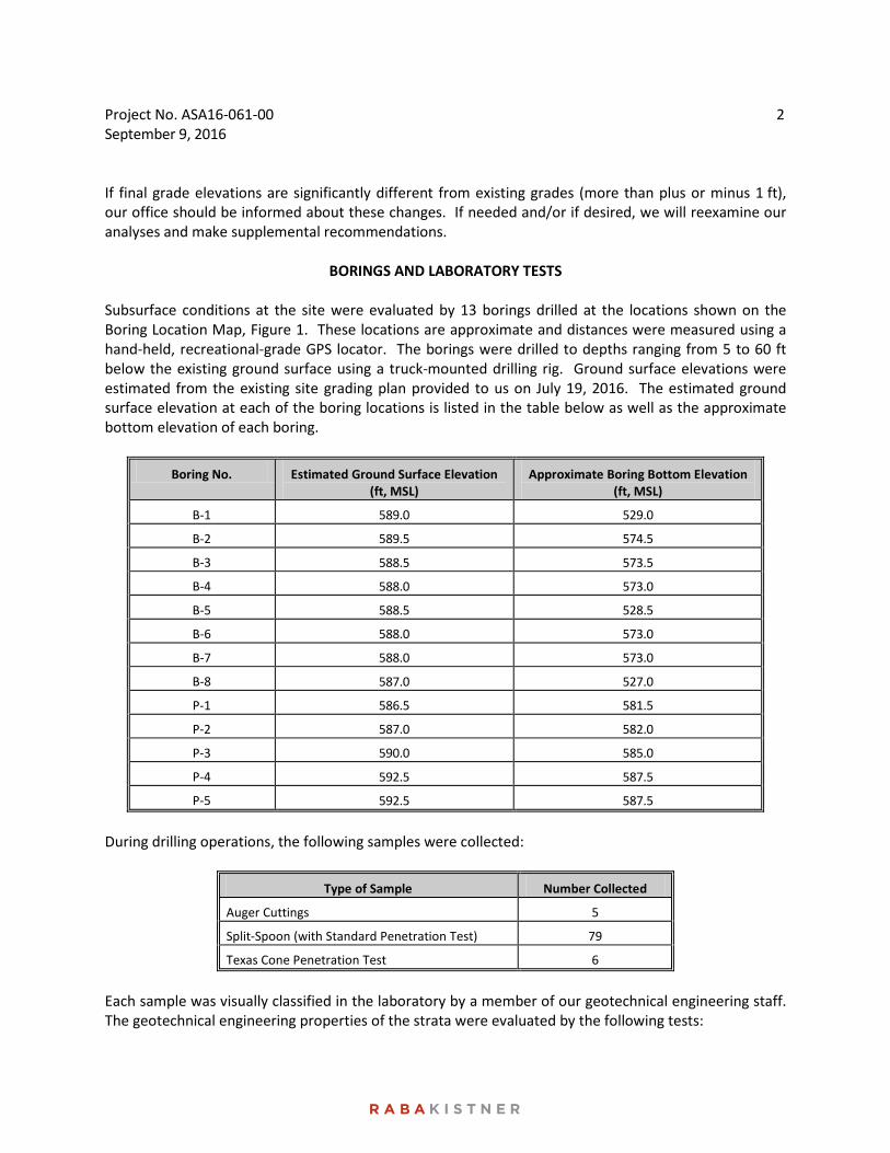
BORINGS AND LABORATORY TESTS Subsurface conditions at the site were evaluated by 13 borings drilled at the locations shown on the Boring Location Map, Figure 1. These locations are approximate and distances were measured using a hand-held, recreational-grade GPS locator. The borings were drilled to depths ranging from 5 to 60 ft below the existing ground surface using a truck-mounted drilling rig. Ground surface elevations were estimated from the existing site grading plan provided to us on July 19, 2016. The estimated ground surface elevation at each of the boring locations is listed in the table below as well as the approximate bottom elevation of each boring.
Boring No. Estimated Ground Surface Elevation (ft, MSL)
Approximate Boring Bottom Elevation (ft, MSL)
B-1 589.0 529.0
B-2 589.5 574.5
B-3 588.5 573.5
B-4 588.0 573.0
B-5 588.5 528.5
B-6 588.0 573.0
B-7 588.0 573.0
B-8 587.0 527.0
P-1 586.5 581.5
P-2 587.0 582.0
P-3 590.0 585.0
P-4 592.5 587.5
P-5 592.5 587.5
During drilling operations, the following samples were collected:
Type of Sample Number Collected
Auger Cuttings 5
Split-Spoon (with Standard Penetration Test) 79
Texas Cone Penetration Test 6
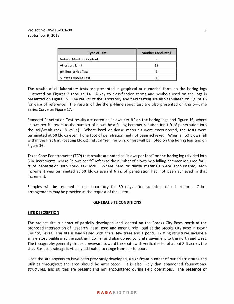
Each sample was visually classified in the laboratory by a member of our geotechnical engineering staff. The geotechnical engineering properties of the strata were evaluated by the following tests:
Project No. ASA16-061-00 September 9, 2016
3
Type of Test Number Conducted
Natural Moisture Content 85
Atterberg Limits 15
pH-lime series Test 1
Sulfate Content Test 1
The results of all laboratory tests are presented in graphical or numerical form on the boring logs illustrated on Figures 2 through 14. A key to classification terms and symbols used on the logs is presented on Figure 15. The results of the laboratory and field testing are also tabulated on Figure 16 for ease of reference. The results of the the pH-lime series test are also presented on the pH-Lime Series Curve on Figure 17. Standard Penetration Test results are noted as “blows per ft” on the boring logs and Figure 16, where “blows per ft” refers to the number of blows by a falling hammer required for 1 ft of penetration into the soil/weak rock (N-value). Where hard or dense materials were encountered, the tests were terminated at 50 blows even if one foot of penetration had not been achieved. When all 50 blows fall within the first 6 in. (seating blows), refusal “ref” for 6 in. or less will be noted on the boring logs and on Figure 16. Texas Cone Penetrometer (TCP) test results are noted as “blows per foot” on the boring log (divided into 6 in. increments) where “blows per ft” refers to the number of blows by a falling hammer required for 1 ft of penetration into soil/weak rock. Where hard or dense materials were encountered, each increment was terminated at 50 blows even if 6 in. of penetration had not been achieved in that increment. Samples will be retained in our laboratory for 30 days after submittal of this report. Other arrangements may be provided at the request of the Client.
GENERAL SITE CONDITIONS SITE DESCRIPTION The project site is a tract of partially developed land located on the Brooks City Base, north of the proposed intersection of Research Plaza Road and Inner Circle Road at the Brooks City Base in Bexar County, Texas. The site is landscaped with grass, few trees and a pond. Existing structures include a single story building at the southern corner and abandoned concrete pavement to the north and west. The topography generally slopes downward toward the south with vertical relief of about 8 ft across the site. Surface drainage is visually estimated to range from fair to poor. Since the site appears to have been previously developed, a significant number of buried structures and utilities throughout the area should be anticipated. It is also likely that abandoned foundations, structures, and utilities are present and not encountered during field operations. The presence of
Project No. ASA16-061-00 September 9, 2016
4
buried structures (old foundations, pavements, brick, abandoned utilities, etc.) should be anticipated during construction. GEOLOGY A review of the Geologic Atlas of Texas, San Antonio Sheet, indicates that this site is naturally underlain with the soils/rocks of the Wilcox Group, which is composed of mudstone with varying amounts of sandstone and lignite. The Wilcox Group may weather to yellowish-brown clay, sandy clay, and sands. The Wilcox Group grades downward into the Midway Group, which is composed of clay, silt, and sand, with some pebbles near its base. Glauconite is often encountered in these soils. Key engineering considerations for development supported on the soils/rock of this for motion typically include the presence of possible water-bearing layers, very hard mudstone/sandstone layers, and the expansive nature of the soil. STRATIGRAPHY In general, the subsurface stratigraphy at this site can be described as fill material to depths ranging from approximately 5 ft to 6 ft that is underlain by dark brown and tan clays which in turn overlies gray clayshale. Gypsum crystals, calcareous deposits and ferrous staining were also encountered in our borings. Each stratum has been designated by grouping soils that possess similar physical and engineering characteristics. The boring log should be consulted for more specific stratigraphic information. Unless noted on the boring log, the lines designating the changes between various strata represent approximate boundaries. The transition between materials may be gradual or may occur between recovered samples. The stratification given on the boring log, or described herein, is for use by RKCI in its analyses and should not be used as the basis of design or construction cost estimates without realizing that there can be variation from what shown or described. The boring log and related information depict subsurface conditions only at the specific location and time where sampling was conducted. The passage of time may result in changes in conditions, interpreted to exist, at or between the locations where sampling was conducted. GROUNDWATER Groundwater was not observed in the borings either during or immediately upon completion of the drilling operations. All borings remained dry during the field exploration phase. However, it is possible for groundwater to exist beneath this site at shallow depths on a transient basis, particularly following periods of precipitation. Fluctuations in groundwater levels may occur due to variation in rainfall, surface water run-off, and the pond pool elevation. The construction process itself may also cause variations in the groundwater level. Based on our experience in this region, shallow groundwater seepage will be encountered at this project site. We believe that groundwater seepage encountered during site earthwork activities and foundation construction may be controlled using temporary earthen berm and conventional sump-and-pump
Project No. ASA16-061-00 September 9, 2016
5
dewatering methods. For deep foundation excavations, this could include the use of temporary casing to reduce groundwater seepage. SEISMIC CONSIDERATIONS Based upon a review of Section 11.4.1 Earthquake Loads – Site Ground Motion of the 2010 Edition of ASCE 7, the following information has been summarized for seismic considerations associated with this site.
• Site Class Definition (Table 20.3-1): Class C. Based on the soil borings conducted for this investigation, the upper 100 feet of soil may be characterized as very dense soil and soft rock.
• Risk-Targeted Maximum Considered Earthquake Ground Motion for a 0.2 sec Spectral Response Acceleration (Figure 22-1): Ss = 0.086 g. Note that the value taken from Figure 22-1 is based on Site Class B and are adjusted per 11.6-1.
• Risk-Targeted Maximum Considered Earthquake Ground Motion for a 1 sec Spectral Response Acceleration (Figure 22-2): S1 = 0.030 g. Note that the value taken from Figure 22-2 is based on Site Class B and are adjusted per 1613.5.3
• Values of Site Coefficient (Table 11.4-1): Fa = 1.2 • Values of Site Coefficient (Table 11.4-2): Fv = 1.7
The Maximum Considered Earthquake Spectral Response Accelerations are as follows:
• 0.2 sec, adjusted based on equation 11.4-1: Sms = 0.103 g • 1 sec, adjusted based on equation 11.4-2: Sm1 = 0.050 g
The Design Spectral Response Acceleration Parameters are as follows:
• 0.2 sec, based on equation 11.4-3: SDS = 0.069 g • 1 sec, based on equation 11.4-4: SD1 = 0.034 g
Based on Section 11.4.5 the Design Spectral Response Spectrum for the Mapped Long-Period Transition Period (Figure 22-12), TL = 12 Sec. The Risk Coefficients using Site-Specific Ground Motion Procedures for Seismic Design on Section 21.2.1.1-Method 1 are as follows:
• 0.2 sec, based on Figure 22-17: CRS = 0.885 • 1 sec, based on Figure 22-18: CR1 = 0.887
Based on the parameters listed above, Tables 11.6-1 or 11.6-2, and calculations performed using the United States Geological Survey (USGS) website, the Seismic Design Category for both short period and 1 second response accelerations is A. As part of the assumptions required to complete the calculations, a Risk Category of “I or II or III” was selected.
Project No. ASA16-061-00 September 9, 2016
6
FOUNDATION RECOMMENDATIONS AND CONSIDERATIONS SITE GRADING Site grading plans can result in changes in almost all aspects of foundation recommendations. We have prepared all foundation recommendations based on the existing ground surface and the stratigraphic conditions encountered at the time of our study. If site grading plans differ from existing grade by more than plus or minus 1 ft, RKCI must be retained to review the site grading plans prior to bidding the project for construction. This will enable RKCI to provide input for any changes in our original recommendations that may be required as a result of site grading operations or other considerations. EXISTING FILL As previously discussed, existing fill was encountered in all our borings to depths ranging from approximately 5 ft to 6 ft below the existing ground surface at the time of our exploration. On the basis of the boring results, laboratory tests, and in the absence of fill placement/compaction records, the existing fill should be considered uncontrolled and potentially compressible. It is not possible to assign reliable soil parameters to the existing fill to calculate settlement. The more positive approach to site development for grade supported structures is to completely remove the existing fill and replace with compacted engineered fill to reduce the settlement risk. As discussed in the following section, the fill remediation may be incorporated with reducing the effects of soil-related movements associated with the presence of the highly expansive fills and soils. Alternatively, the structure may be supported on deep foundations that extend through the existing fill. The existing fill may be reused as general fill provided that the material does not contain deleterious materials. Limited or partial fill improvement could be considered in the pavement areas provided the client understands that partial fill improvement will require acceptance of a greater risk (in exchange for cost savings) for pavement distress and settlement compared to full-depth improvement. EXPANSIVE SOIL-RELATED MOVEMENTS The anticipated ground movements due to swelling of the underlying soils at the site were estimated for slab-on-grade construction using the empirical procedure, Texas Department of Transportation (TxDOT) Tex-124-E, Method for Determining the Potential Vertical Rise (PVR). PVR values ranging from 1-1/2 to 2-1/4 in. were estimated for the stratigraphic conditions encountered in our borings. A surcharge load of 1 psi (concrete slab and sand layer), the surcharge load due to the fill required for the proposed FFE of 591.5 ft, an active zone of 15 ft, and dry moisture conditions were assumed in estimating the above PVR values. The TxDOT method of estimating expansive soil-related movements is based on empirical correlations utilizing the measured plasticity indices and assuming typical seasonal fluctuations in moisture content. If desired, other methods of estimating expansive soil-related movements are available, such as estimations based on swell tests and/or soil-suction analyses. However, the performance of these tests and the detailed analysis of expansive soil-related movements were beyond the scope of the current study. It should also be noted that actual movements can exceed the calculated PVR values due to
Project No. ASA16-061-00 September 9, 2016
7
isolated changes in moisture content (such as due to leaks, landscape watering....) or if water seeps into the soils to greater depths than the assumed active zone depth due to deep trenching or excavations. Overexcavation and Select Fill Replacement Options to reduce the soil related movement for the planned structures may include:
• Structurally suspending the floor slab over the expansive materials with a crawl/ or void space; or • Overexcavating and treating the fill and highly expansive subgrade clays with cement/lime, or
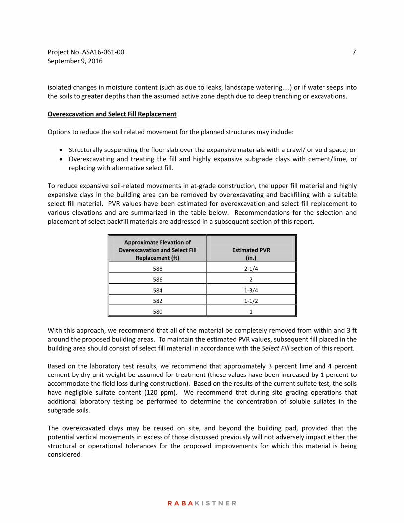
replacing with alternative select fill. To reduce expansive soil-related movements in at-grade construction, the upper fill material and highly expansive clays in the building area can be removed by overexcavating and backfilling with a suitable select fill material. PVR values have been estimated for overexcavation and select fill replacement to various elevations and are summarized in the table below. Recommendations for the selection and placement of select backfill materials are addressed in a subsequent section of this report.
Approximate Elevation of Overexcavation and Select Fill
Replacement (ft)
Estimated PVR
(in.)
588 2-1/4
586 2
584 1-3/4
582 1-1/2
580 1
With this approach, we recommend that all of the material be completely removed from within and 3 ft around the proposed building areas. To maintain the estimated PVR values, subsequent fill placed in the building area should consist of select fill material in accordance with the Select Fill section of this report. Based on the laboratory test results, we recommend that approximately 3 percent lime and 4 percent cement by dry unit weight be assumed for treatment (these values have been increased by 1 percent to accommodate the field loss during construction). Based on the results of the current sulfate test, the soils have negligible sulfate content (120 ppm). We recommend that during site grading operations that additional laboratory testing be performed to determine the concentration of soluble sulfates in the subgrade soils. The overexcavated clays may be reused on site, and beyond the building pad, provided that the potential vertical movements in excess of those discussed previously will not adversely impact either the structural or operational tolerances for the proposed improvements for which this material is being considered.
Project No. ASA16-061-00 September 9, 2016
8
Drainage Considerations When overexcavation and select fill replacement is selected as a method to reduce the potential for expansive soil-related movements at any site, considerations of surface and subsurface drainage may be crucial to construction and adequate foundation performance of the soil-supported structures. Filling an excavation in relatively impervious plastic clays with relatively pervious select fill material creates a “bathtub” beneath the structure, which can result in ponding or trapped water within the fill unless good surface and subsurface drainage is provided. Water entering the fill surface during construction or entering the fill exposed beyond the building lines after construction may create problems with fill moisture control during compaction and increased access for moisture to the underlying expansive clays both during and after construction. Several surface and subsurface drainage design features and construction precautions can be used to limit problems associated with fill moisture. These features and precautions may include but are not limited to the following:
• Installing berms or swales on the uphill side of the construction area to divert surface runoff away from the excavation/fill area during construction;
• Sloping of the top of the subgrade with a minimum downward slope of 1.5 percent out to the base of a dewatering trench located beyond the building perimeter;
• Sloping the surface of the fill during construction to promote runoff of rain water to drainage features until the final lift is placed;
• Sloping of a final, well maintained, impervious clay or pavement surface (downward away from the building) over the select fill material and any perimeter drain extending beyond the building lines, with a minimum gradient of 6 in. in 5 ft;
• Constructing final surface drainage patterns to prevent ponding and limit surface water infiltration at and around the building perimeter;
• Locating the water-bearing utilities, roof drainage outlets and irrigation spray heads outside of the select fill and perimeter drain boundaries; and
• Raising the elevation of the ground level floor slab. Details relative to the extent and implementation of these considerations must be evaluated on a project-specific basis by all members of the project design team. Many variables that influence fill drainage considerations may depend on factors that are not fully developed in the early stages of design. For this reason, drainage of the fill should be given consideration at the earliest possible stages of the project. FOUNDATION OPTIONS We anticipate that the primary structures will be supported on a deep foundation system. However, any structural elements isolated from the main structure are anticipated to be supported on shallow foundation. Special attention must be given to designing shallow foundations immediately adjacent to structures supported by deep foundations, if any. Construction joints should be provided between structures supported on conventional shallow foundations and pier-supported structures to accommodate potential differential movement.
Project No. ASA16-061-00 September 9, 2016
9
The following deep foundation alternatives are available to support the proposed structure:
• Drilled-and-underreamed piers; and • Drilled, straight-shaft piers
The owner may select either one of these foundation systems depending on the performance criteria established for the structures. Cost analyses have not been conducted for any foundation system and are beyond the scope of this study. As discussed in a previous section of this report, it has been our past experience that shallow groundwater seepage will be encountered at this project site. Therefore, we recommend that the bid documents require the foundation contractor to specify unit costs for different lengths of casing that may be required. PIER SPACING Where possible, we recommend that the piers be spaced at a center to center distance of at least three shaft diameters on-center for three bell-diameters for underreamed piers. Such spacing will not require a reduction in the load carrying capacity of the individual piers. If design and/or construction restraints require that piers be spaced closer than the recommended three shaft bell diameters, RKCI must re-evaluate the allowable bearing capacities presented above for the individual piers. Reductions in load carrying capacities may be required depending upon individual loading and spacing conditions. UPLIFT FORCES ON PIERS The pier shafts will be subject to potential uplift forces if the surrounding expansive soils within the active zone are subjected to alternate drying and wetting conditions. The maximum potential uplift force acting on the shaft may be estimated by:
Fu = 80*D where:
Fu = uplift force in kips; and D = diameter of the shaft in feet.
DRILLED-AND-UNDERREAMED PIERS Drilled-and-underreamed piers bearing in either the tan clay stratum or the clayshale stratum may be considered to support the structure. We recommend that piers extend to a minimum depth of 30 ft below the ground surface existing at the time of our study. The piers should be designed as end-bearing
Project No. ASA16-061-00 September 9, 2016
10
units using a maximum allowable bearing pressure of 15 ksf for piers bearing between 30 and 50 ft (approximately elevation 558 and 538 ft)below the existing ground surface or 20 ksf for piers bearing below an elevation of 538 ft. This bearing pressure was evaluated using a calculated factor of safety of at least 3. Allowable Uplift Resistance Resistance to uplift forces exerted on the drilled piers will be provided by the sustained axial compressive force (dead load) plus the allowable uplift resistance provided by the soil. The resistance provided by the soil depends on the bearing capacity of the soils located above the pier underream (bell) and below the active zone. The allowable uplift resistance for underreamed piers founded at the depth recommended above may be estimated using:
Ru = 12*(B2 - D2) for piers bearing between depths of 30 and 50 ft (approximately elevation 558 and 538 ft); and Ru = 17*(B2 - D2) for piers bearing below an elevation of 538 ft
where:
Ru = uplift resistance in kips; B = diameter of the underream in feet; and D = diameter of the shaft in feet.
We recommend that the bell-to-shaft diameter ratio be a minimum of 2, and not exceed 3. Reinforcing steel will be required in each pier shaft to withstand a net force equal to the uplift force minus the sustained compressive load carried by the pier. We recommend that each pier be reinforced to withstand this net force or an amount equal to 1 percent of the cross-sectional area of the shaft, whichever is greater. DRILLED, STRAIGHT-SHAFT PIERS Straight-shaft piers bearing in the underlying clay or clayshale strata may be considered. Consequently, pier capacity could be equal to the summation of the following: (1) the end area of the pier multiplied by the allowable end-bearing pressure and (2) the wall area of the pier socket below the 15 ft active zone into the underlying clay or clay shale surface area multiplied by the allowable side shear resistance. Drilled, straight-shaft piers may also be proportioned using the maximum allowable end-bearing pressure previously presented in the section titled Drilled-and-Underreamed Piers. Allowable side shear resistance is summarized in the following table. The provided values are based on a factor of safety of 2 with respect to the design shear strength.
Project No. ASA16-061-00 September 9, 2016
11
Approximate Elevation (MSL) (ft.)
Depth (ft.)
Allowable Side Shear Resistance (ksf)
573 to 558 15 to 30 1.6
558 to 538 30 to 50 2.0
538 to 528* 50 to 60* 3.0
*Indicates that depth of embedment extends below the depth of our exploration. However, local experience indicates that the clayshale consistency is similar with depth.
Final shaft depths will be based on interpretation of conditions in the field at the time of construction. Due to the variable conditions at this site, RKCI must be present at the time of pier construction to verify the field conditions are similar to those assumed in the preparation of our recommendations. For bid purposes, the owner should anticipate that deeper piers will be required in some areas. Consequently, contractors bidding on the job should include unit costs for various depths of additional pier embedment. Unit costs should include those for both greater and lesser depth in both rock and soil. Allowable Uplift Resistance Resistance to uplift forces exerted on the drilled, straight-shaft piers will be provided by the sustained compressive axial force (dead load) plus the allowable uplift resistance provided by the soil. The resistance provided by the soil depends on the shear strength of the soils adjacent to the pier shaft and below the depth of the resulting active zone. The allowable uplift resistance provided by the soils at this site is presented in the following table.
Approximate Elevation (MSL) (ft.)
Depth (ft.)
Allowable Uplift Resistance (ksf)
573 to 558 15 to 30 1.0
558 to 538 30 to 50 1.7
538 to 528* 50 to 60* 2
*Indicates that depth of embedment extends below the depth of exploration. However, local experience indicates that the clayshale consistency is similar with depth.
These values were evaluated using a factor of safety of 2. Reinforcing steel will be required in each pier shaft to withstand a net force equal to the uplift force minus the sustained compressive load carried by that pier. We recommend that each pier be reinforced to withstand this net force or an amount equal to 1 percent of the cross-sectional area of the shaft, whichever is greater. LATERAL RESISTANCE Resistance to lateral loads and the expected pier behavior under the applied loading conditions will depend not only on subsurface conditions, but also on loading conditions, the pier size, and the engineering properties of the pier. Once pier sizes, concrete strength, and reinforcement are finalized, piers should be analyzed to determine the resulting lateral deflection, maximum bending moment, and ultimate bending moment. This type of analysis is typically performed utilizing a computer analysis
Project No. ASA16-061-00 September 9, 2016
12
program and usually requires a trial and error procedure to appropriately size the piers and meet project tolerances. To assist the design engineer in this procedure, we are providing the following soil parameters for use in analysis. These parameters are in accordance with the input requirements of one of the more commonly used computer programs for laterally loaded piles, the LPile program. If a different program is used for analysis, different parameters and limitations may be required than what were assumed in selecting the parameters given below. Thus, if a program other than LPile is used, RKCI must be notified of the analysis method, so that we can review and revise our recommendations if required. Evaluating the lateral resistance on different pier sizes is outside our scope of work at this time. The soil-related parameters required for input into the LPile program are summarized in the tables below:
Assumed Behavior for Analysis
Approximate Elevation*
(ft) c
(psf) ks
(pci)
Ɛ50 γ’
(pcf) Stiff Clay without free water (Reese) 588 - 582 500 30 0.02 58
Stiff Clay without free water (Reese) 582 - 576 2,000 500 0.007 63
Stiff Clay without free water (Reese) 582 - 538 3,750 1,000 0.005 66
Stiff Clay without free water (Reese) 538 - 528 7,000 2,000 0.004 73
Where: c = undrained cohesion
ks = p-y modulus (static) Ɛ 50 = strain factor γ’ = effective unit weight
The parameters presented in the above table do not include factors of safety. Per the general procedures of Section 1810.3.3.2 of the IBC 2012 edition, the allowable lateral capacity shall not exceed one-half of the lateral load that produces a lateral movement of 1-inch at the ground surface. It should be noted that where piers are spaced closer than three shaft diameters center to center, a modification factor should be applied to the p-y curves to account for a group effect. We recommend the following p-Multipliers for the corresponding center to center pier spacings.
Spacing (in shaft diameters) p-Multiplier
3 1.0
2 0.75
1 0.50
Project No. ASA16-061-00 September 9, 2016
13
SHALLOW FOUNDATIONS The isolated structures, if any, may be founded on shallow foundations or a stiffened engineered beam and slab foundation; provided the selected foundation type can be designed to withstand the anticipated soil-related movements (see Expansive Soil-Related Movements) without impairing either the structural or the operational performance of the structures. Allowable Bearing Capacity Shallow foundations founded on compacted select fill should be proportioned using the design parameters tabulated below.
Shallow Foundation Design Parameters
Minimum depth below final grade 18 in.
Minimum beam or strip footing width 12 in.
Minimum widened beam or spread footing width 18 in.
Maximum allowable bearing pressure for grade beams or strip footings 3,000 psf
Maximum allowable bearing pressure for widened beams or spread footings 3,500 psf
The above presented maximum allowable bearing pressures will provide a factor of safety of about 3, provided that fill is selected and placed as recommended in the Select Fill section of this report. Uplift Resistance Resistance to vertical force (uplift) is provided by the weight of the concrete footing plus the weight of the soil directly above the footing. For this site, it is recommended that the ultimate uplift resistance be based on total unit weights for soil and concrete of 120 pcf and 150 pcf, respectively. The calculated ultimate uplift resistance should be reduced by a factor of safety of 1.2 to calculate the allowable uplift resistance. Lateral Resistance Horizontal loads acting on spread footings will be resisted by passive earth pressure acting on one side of the footing and by base adhesion for footings bearing on engineered fills or natural materials. Resistance to sliding for foundations bearing on natural/compacted soil or select fill should be calculated utilizing an ultimate coefficient of friction of 0.30. The ultimate resistance for these foundations should be limited to 750 psf. An ultimate equivalent fluid pressure of 250 pcf should be utilized to determine the ultimate passive resistance, if required.
Project No. ASA16-061-00 September 9, 2016
14
GRADE BEAMS We recommend that the grade beams interconnecting the piers be structurally suspended due to the anticipated ground movements. A positive void space of at least 12 in., preferably more, should be provided between the soffits of grade beams and the underlying soils. FLOOR SLABS Two alternatives are available to construct the floor slab system. The Owner may select the alternative best satisfying the required performance criteria.
Alternative No. 1: Floor slabs which have high performance criteria or which are movement sensitive in nature, should be structurally suspended because of the anticipated ground movements. A positive void space of at least 12 in., preferably more, should be provided between the slab and the underlying soils (see also Crawl Space Considerations). Areas containing critical entry/exit points to the building, such as doorways, should consider using a suspended system to relieve those areas of heave stresses caused by expansive soils. Alternative No. 2: Floor slabs within the superstructure may be ground supported provided the anticipated movements discussed under the Expansive Soil-Related Movements section of this report will not impair the performance of the floor, frame, or roof systems. If differential movements between the slab and the structure are objectionable, soil-supported floor slabs could be dowelled to the perimeter grade beams. Dowelled slabs that are subjected to heaving will typically crack and develop a plastic hinge along a line which will be approximately 5 to 10 ft inside and parallel to the grade beams. Slabs cast independent of the grade beams, interior columns and partitions should experience minimum cracking, but may create difficulties at critical entry points such as doors and may impact interior partitions that are secured to exterior walls. We recommend that a vapor barrier comprised of polyethylene or polyvinyl chloride (PVC) sheeting be placed between the supporting select fill and the concrete floor slab.
AREA FLATWORK It should be noted that ground-supported flatwork such as walkways, courtyards, etc. will be subject to the same magnitude of potential soil-related movements as discussed previously (see Expansive Soil-Related Movement section). Thus, where these types of elements abut rigid building foundations or isolated/suspended structures, differential movements should be anticipated. As a minimum, we recommend that flexible joints be provided where such elements abut the main structure to allow for differential movement at these locations. Where the potential for differential movement is objectionable, it may be beneficial to consider methods of reducing anticipated movements or to consider structurally suspending critical areas to match the adjacent building performance.
Project No. ASA16-061-00 September 9, 2016
15
FOUNDATION CONSTRUCTION CONSIDERATIONS
SITE DRAINAGE Drainage is an important key to the successful performance of any foundation. Good surface drainage should be established prior to and maintained after construction to help prevent water from ponding within or adjacent to the building foundation and to facilitate rapid drainage away from the building foundation. Failure to provide positive drainage away from the structure can result in localized differential vertical movements in soil supported foundations and floor slabs (which can in turn result in cracking in the sheetrock partition walls, and shifting of ceiling tiles, as well as improper operation of windows and doors). Current ordinances, in compliance with the Americans with Disabilities Act (ADA), may dictate maximum slopes for walks and drives around and into new buildings. These slope requirements can result in drainage problems for buildings supported on expansive soils. We recommend that, on all sides of the building, the maximum permissible slope be provided away from the building. Also to help control drainage in the vicinity of the structure, we recommend that roof/gutter downspouts and landscaping irrigation systems not be located adjacent to the building foundation. Where a select fill overbuild is provided outside of the floor slab/foundation footprint, the surface should be sealed with an impermeable layer (clay cap, geomebrane or pavement) to reduce infiltration of both irrigation and surface waters. Careful consideration should also be given to the location of water bearing utilities, as well as to provisions for drainage in the event of leaks in water bearing utilities. All leaks should be immediately repaired. Other drainage and subsurface drainage issues are discussed in the Expansive Soil-Related Movements section of this report and under Pavement Construction Considerations. Furthermore, as discussed in a previous section of this report, it has been our past experience that shallow groundwater seepage may be encountered at the project site. Hence, we recommend that drainage related issues be thoroughly addressed by the design team. SITE PREPARATION Building areas and all areas to support select fill should be stripped of all vegetation and organic topsoil. Exposed subgrades should be thoroughly proofrolled in order to locate weak, compressible zones. A fully-loaded dump truck or a similar heavily-loaded piece of construction equipment should be used for planning purposes. Proofrolling operations should be observed by the Geotechnical Engineer or their representative to document subgrade condition and preparation. Weak or soft areas identified during proofrolling should be removed and replaced with suitable, compacted on-site clays, free of organics, oversized materials, and degradable or deleterious materials. Upon completion of the proofrolling operations and just prior to fill placement or slab construction, the exposed subgrade should be moisture conditioned by scarifying to a minimum depth of 6 in. and
Project No. ASA16-061-00 September 9, 2016
16
recompacting to a minimum of 95 percent of the maximum density determined from TxDOT, Tex-114-E, Compaction Test. The moisture content of the subgrade should be maintained within the range of optimum moisture content to 3 percentage points above optimum moisture content until permanently covered. SELECT FILL Recommendations for select fill materials are provided below.
Imported Crushed Limestone Base – Imported crushed limestone base materials should be should be crushed stone or gravel aggregate. We recommend that materials specified for use as select fill meet the TxDOT 2014 Standard Specifications for Construction and Maintenance of Highways, Streets and Bridges, Item 247, Flexible Base, Type A or B, Grades 1-2 or 3. Treated Onsite Materials – Lime/cement/super slurry treatment of the onsite soils may be considered in reducing the soil plasticity index (TxDOT Item 260 for Lime and Item 275 for cement). A sufficient quantity of product should be mixed with the subgrade soils to reduce the soil-product mixture plasticity index to approximately 15 or less. We estimate that approximately 5 percent lime and 6 percent cement by dry unit weight be assumed for treatment. If cement treatment is selected, the mellowing period may be reduced to 24 hours prior to placing subsequent lifts. The final lift shall be cured for a minimum of 48 hours prior to placement of building foundation.
Alternatively super slurry treatment can be used to reduce the PI and increase the soil stiffness. However, this is a proprietary product and the supplier should be contacted to evaluate the appropriate dosage rate. For this process, the contractor should allow a minimum of 12 hours, preferably 24 hours, before placing subsequent lifts.
We recommend that during site grading operations that additional laboratory testing be performed to determine the appropriate treatment dosage rate and concentration of soluble sulfates in the subgrade and imported soils. Granular Pit Run Materials – Granular pit run materials should consist of GC, SC & combination soils (clayey gravels), as classified according to the Unified Soil Classification System (USCS). Alternative select fill materials shall have a maximum liquid limit not exceeding 40, a plasticity index between 7 and 15, and a maximum particle size not exceeding 4 inch. In addition, if these materials are utilized, grain size analyses and Atterberg Limits must be performed during placement at a rate of one test each per 5,000 cubic yards of material due to the high degree of variability associated with pit-run materials. Low PI Materials – Low PI materials should consist of CL clays, as classified according to the Unified Soil Classification System (USCS). Alternative select fill materials shall have a maximum liquid limit not exceeding 40, a plasticity index between 7 and 15, and a maximum particle size not exceeding 4 inch. In addition, if these materials are utilized, grain size analyses and
Project No. ASA16-061-00 September 9, 2016
17
Atterberg Limits must be performed during placement at a rate of one test each per 5,000 cubic yards of material due to the high degree of variability associated with these materials.
Select fill should be placed in loose lifts not exceeding 8 in. in thickness and compacted to at least 95 percent of maximum density as determined by TxDOT, Tex-113-E, Compaction Test. The moisture content of the fill should be maintained within the range of 2 percentage points below to 2 percentage points above the optimum moisture content until final compaction for imported crushed limestone base or granular pit run materials. For low PI materials, the moisture content of the fill should be maintained within the range of optimum to plus 3 percentage points above the optimum moisture content until final compaction. Potentially expansive clays (PI greater than 15) should not be used as select fill unless the clay is treated with lime or cement to reduce the plasticity index. If lime or cement treatment of the highly expansive clays is considered as an option, we recommend that approximately 3 percent lime and 4 percent cement by dry unit weight be assumed for treatment (these values have been increased by 1 percent to accommodate the field loss during construction). Alternatively, untreated material may be used in areas where potential vertical movements will not adversely impact either the structural or operational tolerances for the individual foundations, slabs or walls for which this material is being considered. SHALLOW FOUNDATION EXCAVATIONS Shallow foundation excavations should be observed by the Geotechnical Engineer or their representative prior to placement of reinforcing steel and concrete. This is necessary to observe that the soils at the bottom of the excavations are similar to those encountered in our borings and that excessive loose materials and water are not present in the excavations. If soft soils are encountered in the foundation excavations, they should be removed and replaced with a compacted non-expansive fill material or lean concrete up to the design foundation bearing elevations. DRILLED PIERS Each drilled pier excavation must be examined by an RKCI representative who is familiar with the geotechnical aspects of the soil stratigraphy, the structural configuration, foundation design details and assumptions, prior to placing concrete. This is to observe that:
• The shaft and/or bell has been excavated to the specified dimensions at the correct depth established by the previously mentioned criteria;
• The bell is concentric with the pier shaft; • The shaft has been drilled plumb within specified tolerances along its total length; and • Excessive cuttings, buildup and soft, compressible materials have been removed from
the bottom of the excavation. High-powered, high-torque drilling equipment should be anticipated for drilled pier construction at this site (see also Excavation Equipment).
Project No. ASA16-061-00 September 9, 2016
18
Reinforcement and Concrete Placement Reinforcing steel should be checked for size and placement prior to concrete placement. Placement of concrete should be accomplished as soon as possible after excavation to reduce changes in the moisture content or the state of stress of the foundation materials. No foundation element should be left open overnight without concreting. Temporary Casing Groundwater seepage was not observed in the test borings at the time of our subsurface exploration. However, it has been our past experience that shallow groundwater seepage and/or side sloughing is likely to be encountered at the time of construction, depending on climatic conditions prevalent at the time of construction. Therefore, we recommend that the bid documents require the foundation contractor to specify unit costs for different lengths of casing that may be required. EXCAVATION SLOPING AND BENCHING If utility trenches or other excavations extend to or below a depth of 5 ft below construction grade, the contractor or others shall be required to develop a trench safety plan to protect personnel entering the trench or trench vicinity. The collection of specific geotechnical data and the development of such a plan, which could include designs for sloping and benching or various types of temporary shoring, are beyond the scope of the current study. Any such designs and safety plans shall be developed in accordance with current OSHA guidelines and other applicable industry standards. EXCAVATION EQUIPMENT Our boring logs are not intended for use in determining construction means and methods and may therefore be misleading if used for that purpose. We recommend that earth-work and utility contractors interested in bidding on the work perform their own tests in the form of test pits to determine the quantities of the different materials to be excavated, as well as the preferred excavation methods and equipment for this site. CRAWL SPACE CONSIDERATIONS If the structurally suspended floor system described as Alternative No. 1 under the Floor Slab section of this report is selected, several special design issues should be considered for the resulting subfloor crawl space. These issues are discussed below. Ventilation Observations by members of our firm of open crawl spaces have indicated a need for adequate subfloor ventilation for suspended floor systems. Such ventilation helps promote evaporation of subgrade moisture which may accumulate in spite of special surface and subsurface drainage features. As a minimum, free flowing passive vents may need to be installed along the perimeter beam to provide cross ventilation. If structural configurations will limit the free flow of air through passive vents, forced air,
Project No. ASA16-061-00 September 9, 2016
19
power vents should be installed. All vents should be designed such that they will not allow the drainage of surface water into the crawl space. Below Slab Utilities A minimum clearance of 12 in. has been recommended between both the grade beams and floor slab and the underlying finished subgrade should a suspended floor system be employed. Such a minimum clearance is also recommended between the subgrade and any utilities which may be suspended from the underside of the floor. This clearance will allow swell-related subgrade movements without damaging the utilities. It is recommended that the utility clearance not be provided by the addition of narrow trenches running parallel to and immediately below the utilities, unless proper slopes and drainage outlets are provided to prevent ponding of water in the trenches. Drainage As discussed throughout this report, positive drainage is a key factor in the long term performance of any foundation. This is not only critical around the perimeter of the structure, but also in any subfloor crawl spaces. In crawl areas, surface drainage should be established that will direct water away from and will prevent water from ponding adjacent to piers. This positive drainage should be maintained both prior to and after construction. Compaction control of the backfill around the perimeter of the building following the placement of soil retainer blocks is critical to the drainage away from the building following construction. Materials for the backfill around the perimeter of the building should be the on-site clays. These materials should be compacted in uniformly thin lifts (8-inch maximum loose thickness) to at least 90 percent of the maximum dry density as determined by TxDOT Test Method TEX-114-E. These clays should be placed and compacted at optimum to plus 3 percent above optimum moisture content. Compaction by hand operated mechanical tampers will help to avoid damage to the soil retainer blocks. Following backfilling operations the soil retainer blocks should be checked to see that they have not been broken or collapsed during the compaction operations. Any soil retainer blocks that are broken or collapsed should be repaired or replaced. Carton Forms When carton forms are used to form subfloor void spaces, the forms often get wet or sometimes absorb water from humid air. This can result in collapse of the forms during the placement of concrete, thus diminishing the design void space. Conversely, if the carton forms are too strong and do not decompose sufficiently with time, they may not collapse as soil heave occurs, resulting in heave damage to the floor slab. Where there is sufficient moisture to cause the appropriate deterioration after construction, there may be a resulting moisture problem in the floor slab as a result of poor ventilation and the accumulation of condensation within the resulting unventilated void space. The lack of ventilation may also result in increased soil movements that will diminish the design void space. For these reasons, we recommend that where possible, consideration be given to methods other than the use of carton forms to form the recommended void space beneath floor slabs. If project specifics require the use of carton forms, then as
Project No. ASA16-061-00 September 9, 2016
20
a minimum, care should be taken to ensure that the carton forms are designed for use in the project location, and that carton forms are properly stored, protected, and installed during construction. INTERIOR WALLS It is not uncommon for cracking to occur in interior partition walls that are supported by a “floating” floor slab and structurally tied to either an interior column or an exterior wall supported by deep foundations. This should be taken into account during the design phase of the project if a “floating” slab foundation is used to support the proposed building. UTILITIES Utilities which project through slab-on-grade, slab-on-fill, “floating” floor slabs, or any other rigid unit should be designed with either some degree of flexibility or with sleeves. Such design features will help reduce the risk of damage to the utility lines as vertical movements occur. These types of slabs will generally be constructed as monolithic, grid type beam and slab foundations or as a “floating” floor slab described as Alternate No. 2 under the Floor Slab section of this report. Our experience indicates that significant settlement of backfill can occur in utility trenches, particularly when trenches are deep, when backfill materials are placed in thick lifts with insufficient compaction, and when water can access and infiltrate the trench backfill materials. The potential for water to access the backfill is increased where water can infiltrate flexible base materials due to insufficient penetration of curbs, and at sites where geological features can influence water migration into utility trenches. It is our belief that another factor which can significantly impact settlement is the migration of fines within the backfill into the open voids in the underlying free-draining bedding material. To reduce the potential for settlement in utility trenches, we recommend that consideration be given to the following:
• All backfill materials should be placed and compacted in controlled lifts appropriate for the type of backfill and the type of compaction equipment being utilized and all backfilling procedures should be tested and documented.
• Curbs should completely penetrate base materials and be installed to a sufficient depth to reduce water infiltration beneath the curbs into the pavement base materials.
• Consideration should be given to wrapping free-draining bedding gravels with a geotextile fabric (similar to Mirafi 140N) to reduce the infiltration and loss of fines from backfill material into the interstitial voids in bedding materials.
PAVEMENT RECOMMENDATIONS
Recommendations for both flexible and rigid pavements are presented in this report. The Owner and/or design team may select either pavement type depending on the performance criteria established for the project. In general, flexible pavement systems have a lower initial construction cost as compared to rigid pavements. However, maintenance requirements over the life of the pavement are typically much greater for flexible pavements. This typically requires regularly scheduled observation and repair, as
Project No. ASA16-061-00 September 9, 2016
21
well as overlays and/or other pavement rehabilitation at approximately one-half to two-thirds of the design life. Rigid pavements are generally more "forgiving", and therefore tend to be more durable and require less maintenance after construction. For either pavement type, drainage conditions will have a significant impact on long term performance, particularly where permeable base materials are utilized in the pavement section. Drainage considerations are discussed in more detail in a subsequent section of this report. SUBGRADE CONDITIONS In pavement areas, complete removal and replacement of the existing fill would provide the lowest risk for unacceptable settlement of the pavement. In lieu of full-depth fill remediation, limited fill remediation could be considered provided the client understands that partial fill remediation will require acceptance of a greater risk for pavement distress compared to full-depth remediation. The risk potential cannot be quantified. Partial fill remediation in pavement areas could be removed and replaced to depths up to 2 ft below pavement subgrade. Greater depths of removal and replacement may be required based on observation during proofrolling. The existing fill may be re-used for engineered fill provided the material is placed as discussed herein. To further reduce the potential for unacceptable settlement in pavement areas, geogrid could be placed at the base of the excavation or pavement subgrade. We have assumed the subgrade in pavement areas will consist of the recompacted existing fill or natural material, placed and compacted as recommended in the On-Site Fill Material section of this report. Based on our experience with similar subgrade soils, we have assigned a California Bearing Ratio (CBR) value of 3.0 for use in pavement thickness design analyses. It should be noted that the pavement sections derived in the following sections are structurally adequate for the given traffic levels and subgrade strength, but do not consider the long-term effects of pavement roughness due to settlement of the onsite existing fill or heave of the underlying highly plastic clay. SWELL/HEAVE POTENTIAL SWELL/HEAVE POTENTIAL The subgrade soils at this site are classified as highly plastic, and the potential exists for the soils to expand or heave when water is introduced, causing the pavement to become rough or uneven over time. Pavement roughness is generally defined as an expression of irregularities in the pavement surface that adversely affect the ride quality of a vehicle (and thus the user). Pavement heave can be reduced through various measures but cannot be totally eliminated without full removal of the problematic soil. Measures available for reducing heave include:
• Soil Treatment with Lime or Other Chemicals • Removal and Replacement of High PI Soils • Drains or Barriers to Collect or Inhibit Moisture Infiltration
Soil treatment with lime (or other chemicals) is typically used to reduce the swelling potential of the upper portion of the pavement subgrade containing moderately plastic soils. This is an option and is not

Project No. ASA16-061-00 September 9, 2016
22
required as part of the pavement thickness design presented above. Lime and water are mixed with the top 6 to 12 inches (or possibly more) of the subgrade and allowed to mellow or cure for a period of time. After mellowing the soil-lime mixture is compacted to form a strong soil matrix that can improve pavement performance and potentially reduce soil heave. However, the chemical reaction between the calcium-based additives and the sulfates and/or sulfide minerals in the soil can create a heaving problem on the pavement. Based on the results of the current sulfate test, the soils have negligible sulfate content (120 ppm). Consequently, the traditional lime stabilization can be used according to the Texas Department of Transportation – Guidelines for treatment of sulfate-Rich soils and Bases in pavement Structures, 09/2005. In addition, capturing water infiltration via French drains, pavement edge drains, or inhibiting water through the use of vertical moisture barriers would reduce the potential for heave since one important component of the heaving mechanism, water, would be reduced. Geogrids are also another tool available that may help reduce the damage that heaving subgrades cause to flexible pavements and may be considered in addition to or as an alternative to other mitigation techniques. DESIGN INFORMATION The following recommendations were prepared using the DARWin 3.1 software program which utilizes a procedure based on the 1993 “Guide for the Design of Pavement Structures” by the American Association of State Highway and Transportation Officials (AASHTO). The following recommendations were prepared assuming a 20-yr design life and Equivalent Single Axle Loads (ESAL’s) of 15,000 for light duty pavements and 50,000 for heavy duty pavements. This traffic frequency is approximately equivalent to 1 and 3 tractor-trailer trucks per day for a design period of 20 years for light and heavy duty pavements, respectively. The Project Civil Engineer should review anticipated traffic loading and frequencies to verify that the assumed traffic loading and frequency is appropriate for the intended use of the facility. FLEXIBLE PAVEMENT Flexible pavement sections recommended for this site are as listed in the table below:
Flexible Pavement Components
Traffic Type Flexible Base (in.) Surface Course (in.)
Light Duty Traffic (parking areas) 8 2
Heavy Duty Traffic (entrances, driveways, and channelized, if any) 12 2
10 3
Based on our experience, the reported sections often perform adequately; however, maintenance or an overlay is generally needed sooner than would be required for a thicker design section. Consideration could be given to adding additional asphalt (i.e. an additional 1 in.) or incorporating a geotextile or geogrid below the flexible base. These are options and are not required. The geogrid reinforcement should conform to TxDOT Type 2 geogrid, or an approved substitute. If geogrid is used in the provided
Project No. ASA16-061-00 September 9, 2016
23
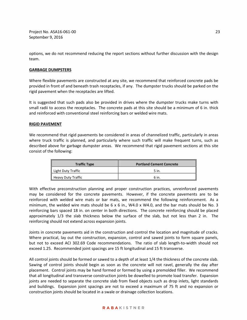
options, we do not recommend reducing the report sections without further discussion with the design team. GARBAGE DUMPSTERS Where flexible pavements are constructed at any site, we recommend that reinforced concrete pads be provided in front of and beneath trash receptacles, if any. The dumpster trucks should be parked on the rigid pavement when the receptacles are lifted. It is suggested that such pads also be provided in drives where the dumpster trucks make turns with small radii to access the receptacles. The concrete pads at this site should be a minimum of 6 in. thick and reinforced with conventional steel reinforcing bars or welded wire mats. RIGID PAVEMENT We recommend that rigid pavements be considered in areas of channelized traffic, particularly in areas where truck traffic is planned, and particularly where such traffic will make frequent turns, such as described above for garbage dumpster areas. We recommend that rigid pavement sections at this site consist of the following:
Traffic Type Portland Cement Concrete
Light Duty Traffic 5 in.
Heavy Duty Traffic 6 in.
With effective preconstruction planning and proper construction practices, unreinforced pavements may be considered for the concrete pavements. However, if the concrete pavements are to be reinforced with welded wire mats or bar mats, we recommend the following reinforcement. As a minimum, the welded wire mats should be 6 x 6 in., W4.0 x W4.0, and the bar mats should be No. 3 reinforcing bars spaced 18 in. on center in both directions. The concrete reinforcing should be placed approximately 1/3 the slab thickness below the surface of the slab, but not less than 2 in. The reinforcing should not extend across expansion joints. Joints in concrete pavements aid in the construction and control the location and magnitude of cracks. Where practical, lay out the construction, expansion, control and sawed joints to form square panels, but not to exceed ACI 302.69 Code recommendations. The ratio of slab length-to-width should not exceed 1.25. Recommended joint spacings are 15 ft longitudinal and 15 ft transverse. All control joints should be formed or sawed to a depth of at least 1/4 the thickness of the concrete slab. Sawing of control joints should begin as soon as the concrete will not ravel, generally the day after placement. Control joints may be hand formed or formed by using a premolded filler. We recommend that all longitudinal and transverse construction joints be dowelled to promote load transfer. Expansion joints are needed to separate the concrete slab from fixed objects such as drop inlets, light standards and buildings. Expansion joint spacings are not to exceed a maximum of 75 ft and no expansion or construction joints should be located in a swale or drainage collection locations.
Project No. ASA16-061-00 September 9, 2016
24
If possible, the pavement should develop a minimum slope of 0.015 ft/ft to provide surface drainage. Reinforced concrete pavement should cure a minimum of 3 and 7 days before allowing automobile and truck traffic, respectively.
PAVEMENT CONSTRUCTION CONSIDERATIONS SUBGRADE PREPARATION Areas to support pavements should be stripped of all vegetation, organic topsoil and the existing fill may be remediated as previously discussed. The exposed subgrade should be proofrolled in accordance with the recommendations in the Site Preparation section. DRAINAGE CONSIDERATIONS As with any soil-supported structure, the satisfactory performance of a pavement system is contingent on the provision of adequate surface and subsurface drainage. Insufficient drainage which allows saturation of the pavement subgrade and/or the supporting granular pavement materials will greatly reduce the performance and service life of the pavement systems. Surface and subsurface drainage considerations crucial to the performance of pavements at this site include (but are not limited to) the following:
1) Any known natural or man-made subsurface seepage at the site which may occur at sufficiently shallow depths as to influence moisture contents within the subgrade should be intercepted by drainage ditches or below grade French drains.
2) Final site grading should eliminate isolated depressions adjacent to curbs which may allow surface water to pond and infiltrate into the underlying soils. Curbs should completely penetrate base materials and should be installed to sufficient depth to reduce infiltration of water beneath the curbs.
3) Pavement surfaces should be maintained to help minimize surface ponding and to provide rapid sealing of any developing cracks. These measures will help reduce infiltration of surface water downward through the pavement section.
ON-SITE FILL MATERIAL As discussed previously, the pavement recommendations presented in this report were prepared assuming that on-site soils will be used for fill grading in proposed pavement areas. If used, we recommend that on-site soils be placed in loose lifts not exceeding 8 in. in thickness and compacted to at least 95 percent of the maximum density as determined by Tex-114-E. The moisture content of the fill should be maintained within the range of optimum water content to 3 percentage points above the optimum water content until permanently covered. We recommend that fill materials be free of roots and other organic or degradable material. We also recommend that the maximum particle size not exceed 4 in. or one half the lift thickness, whichever is smaller.
Project No. ASA16-061-00 September 9, 2016
25
TREATMENT OF SUBGRADE Cement or lime treatment of the subgrade soils, if utilized, should be in accordance with the TxDOT Standard Specifications, Item 260. A sufficient quantity of product should be mixed with the subgrade soils to reduce the soil-treated mixture plasticity index to 20 or less. Based on the results of the pH Lime Series Curve presented on Figure 17, we recommend that at least 3 percent hydrated lime by weight be used to reduce the PI of the subgrade clays. For cement, we estimate that 4 percent by weight may be assumed. Treated subgrade soils should be compacted to a minimum of 95 percent of the maximum density at a moisture content within the range of optimum moisture content to 3 percentage points above the optimum moisture content as determined by Tex-113-E. Based on the results of the current sulfate test, the soils have negligible sulfate content (120 ppm). However, if lime or cement treatment is considered as a method to improve pavement subgrade conditions, it is also recommended to perform additional laboratory testing to determine the concentration of soluble sulfates in the subgrade soils, in order to investigate the potential for a recently reported adverse reaction to lime in certain sulfate-containing soils. The adverse reaction, referred to as sulfate-induced heave, has been known to cause cohesive subgrade soils to swell in short periods of time, resulting in pavement heaving and possible failure. FLEXIBLE BASE COURSE The flexible base course should be crushed limestone conforming to TxDOT Standard Specifications, Item 247, Type A, Grade 1-2. Base course should be placed in lifts with a maximum thickness of 8 in. and compacted to a minimum of 95 percent of the maximum density at a moisture content within the range of 2 percentage points below to 2 percentage points above the optimum moisture content as determined by Tex-113-E. ASPHALTIC CONCRETE SURFACE COURSE The asphaltic concrete surface course should conform to TxDOT Standard Specifications, Item 340, Type D. The asphaltic concrete should be compacted to a minimum of 92 percent of the maximum theoretical specific gravity (Rice) of the mixture determined according to Test Method Tex-227-F. Pavement specimens, which shall be either cores or sections of asphaltic pavement, will be tested according to Test Method Tex-207-F. The nuclear-density gauge or other methods which correlate satisfactorily with results obtained from project roadway specimens may be used when approved by the Engineer. Unless otherwise shown on the plans, the Contractor shall be responsible for obtaining the required roadway specimens at their expense and in a manner and at locations selected by the Engineer. PORTLAND CEMENT CONCRETE The Portland cement concrete should be air entrained to result in a 4 percent plus/minus 1 percent air, should have a maximum slump of 5 inches, and should have a minimum 28-day compressive strength of 3,000 psi. A liquid membrane-forming curing compound should be applied as soon as practical after
Project No. ASA16-061-00 September 9, 2016
26
broom finishing the concrete surface. The curing compound will help reduce the loss of water from the concrete. The reduction in the rapid loss in water will help reduce shrinkage cracking of the concrete. The Mr of concrete is a measure of the flexural strength of the concrete as determined by breaking concrete beam test specimens. A Mr of approximately 450 to 550 psi at 28 days was used in the analysis and is typical of local concrete production. MISCELLANEOUS PAVEMENT RELATED CONSIDERATIONS Drainage Considerations As with any soil-supported structure, the satisfactory performance of a pavement system is contingent on the provision of adequate surface and subsurface drainage. Insufficient drainage which allows saturation of the pavement subgrade and/or the supporting granular pavement materials will greatly reduce the performance and service life of the pavement systems. Surface and subsurface drainage considerations crucial to the performance of pavements at this site include (but are not limited to) the following:
• Any known natural or man-made subsurface seepage at the site which may occur at sufficiently shallow depths as to influence moisture contents within the subgrade should be intercepted by drainage ditches or below grade French drains.
• Final site grading should eliminate isolated depressions adjacent to curbs, which may allow surface water to pond and infiltrate into the underlying soils. Curbs should be installed to a sufficient depth to reduce infiltration of water beneath the curbs and into the pavement base materials.
• Pavement surfaces should be maintained to help minimize surface ponding and to provide rapid sealing of any developing cracks. These measures will help reduce infiltration of surface water downward through the pavement section.
Longitudinal Cracking It should be understood that asphalt pavement sections in highly expansive soil environments, such as those encountered at this site, can develop longitudinal cracking along unprotected pavement edges. In the semi-arid climate of south central Texas this condition typically occurs along the unprotected edges of pavements where moisture fluctuation is allowed to occur over the lifetime of the pavements. Pavements that do not have a protective barrier to reduce moisture fluctuation of the highly expansive clay subgrade between the exposed pavement edge and that beneath the pavement section tend to develop longitudinal cracks 1 to 4 ft from the edge of the pavement. Once these cracks develop, further degradation and weakening of the underlying granular base may occur due to water seepage through the cracks. The occurrence of these cracks can be more prevalent in the absence of lateral restraint and embankments. This problem can best be addressed by providing either a horizontal or vertical moisture barrier at the unprotected pavement edge.
Project No. ASA16-061-00 September 9, 2016
27
At a minimum, we recommend that the curbs are constructed such that the depth of the curb extends through the entire depth of the granular base material and into the subgrade to act as a protective barrier against the infiltration of water into the granular base. In most cases, a longitudinal crack does not immediately compromise the structural integrity of the pavement system. However, if left unattended, infiltration of surface water runoff into the crack will result in isolated saturation of the underlying base. This will result in pumping of the flexible base, which could lead to rutting, cracking, and pot-holes. For this reason, we recommend that the owner of the facility immediately seal the cracks and develop a periodic sealing program. Pavement Maintenance Regular pavement maintenance is critical in maintaining pavement performance over a period of several years. All cracks that develop in asphalt pavements should be regularly sealed. Areas of moderate to severe fatigue cracking (also known as alligator cracking) should be sawcut and removed. The underlying base should be checked for contamination or loss of support and any insufficiencies fixed or removed and the entire area patched. All cracks that develop in concrete pavements should be routed and sealed regularly. Joints in concrete pavements should be maintained to reduce the influx of incompressible materials that restrain joint movement and cause spalling and/or cracking. Other typical TxDOT or City of San Antonio maintenance techniques should be followed as required. Construction Traffic Construction traffic on prepared subgrade, granular base should be restricted as much as possible until the protective asphalt surface pavement is applied. Significant damage to the underlying layers resulting in weakening may occur if heavily loaded vehicles are allowed to use these areas.
CONSTRUCTION RELATED SERVICES CONSTRUCTION MATERIALS TESTING AND OBSERVATION SERVICES As presented in the attachment to this report, Important Information About Your Geotechnical Engineering Report, subsurface conditions can vary across a project site. The conditions described in this report are based on interpolations derived from a limited number of data points. Variations will be encountered during construction, and only the geotechnical design engineer will be able to determine if these conditions are different than those assumed for design. Construction problems resulting from variations or anomalies in subsurface conditions are among the most prevalent on construction projects and often lead to delays, changes, cost overruns, and disputes. These variations and anomalies can best be addressed if the geotechnical engineer of record, RKCI is retained to perform construction observation and testing services during the construction of the project. This is because:
Project No. ASA16-061-00 September 9, 2016
28
• RKCI has an intimate understanding of the geotechnical engineering report’s findings and recommendations. RKCI understands how the report should be interpreted and can provide such interpretations on site, on the client’s behalf.
• RKCI knows what subsurface conditions are anticipated at the site. • RKCI is familiar with the goals of the owner and project design professionals, having
worked with them in the development of the geotechnical workscope. This enables RKCI to suggest remedial measures (when needed) which help meet the owner’s and the design teams’ requirements.
• RKCI has a vested interest in client satisfaction, and thus assigns qualified personnel whose principal concern is client satisfaction. This concern is exhibited by the manner in which contractors’ work is tested, evaluated and reported, and in selection of alternative approaches when such may become necessary.
• RKCI cannot be held accountable for problems which result due to misinterpretation of our findings or recommendations when we are not on hand to provide the interpretation which is required.
BUDGETING FOR CONSTRUCTION TESTING Appropriate budgets need to be developed for the required construction testing and observation activities. At the appropriate time before construction, we advise that RKCI and the project designers meet and jointly develop the testing budgets, as well as review the testing specifications as it pertains to this project. Once the construction testing budget and scope of work are finalized, we encourage a preconstruction meeting with the selected contractor to review the scope of work to make sure it is consistent with the construction means and methods proposed by the contractor. RKCI looks forward to the opportunity to provide continued support on this project, and would welcome the opportunity to meet with the Project Team to develop both a scope and budget for these services.
* * * * * * * * * * * * * * * * * *

ATTACHMENTS
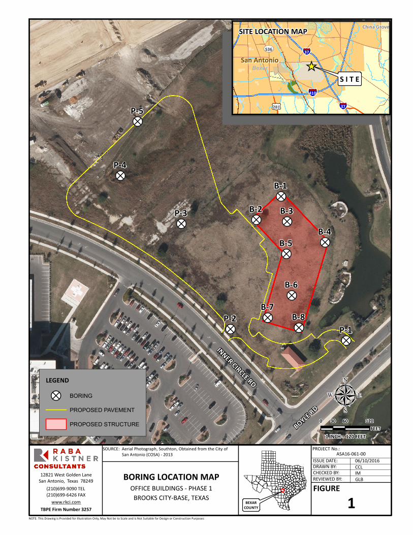
!?!?
!?
!?
!?
!? !?
!?
!?
!?!?
!?
!?B-5
B-6B-7
B-8
B-1
B-4B-3B-2
P-5
P-4
P-3
P-2P-1
INNER CIRCLE RD
BOYLE RD
CITY B
ASE L
ANDIN
G
BORING LOCATION MAP OFFICE BUILDINGS - PHASE 1
BROOKS CITY-BASE, TEXAS
PROJECT No.:ASA16-061-00
DRAWN BY:ISSUE DATE:
REVIEWED BY:CHECKED BY:
CCL06/10/2016
GLBIM
NOTE: This Drawing is Provided for Illustration Only, May Not be to Scale and is Not Suitable for Design or Construction Purposes
µLEGEND
!? BORING
PROPOSED PAVEMENT
PROPOSED STRUCTURE
SOURCE: Aerial Photograph, Southton, Obtained from the City of San Antonio (COSA) - 2013
San AntonioSan Antonio
China Grove
§̈¦410
§̈¦37
§̈¦37£¤281
UV536
Bexar
SITE LOCATION MAP
S I T E
FIGURE1BEXAR
COUNTY
_̂
TBPE Firm Number 3257
12821 West Golden LaneSan Antonio, Texas 78249
(210)699-9090 TEL(210)699-6426 FAX
www.rkci.com
0 60 12030FEET
1 INCH = 120 FEET
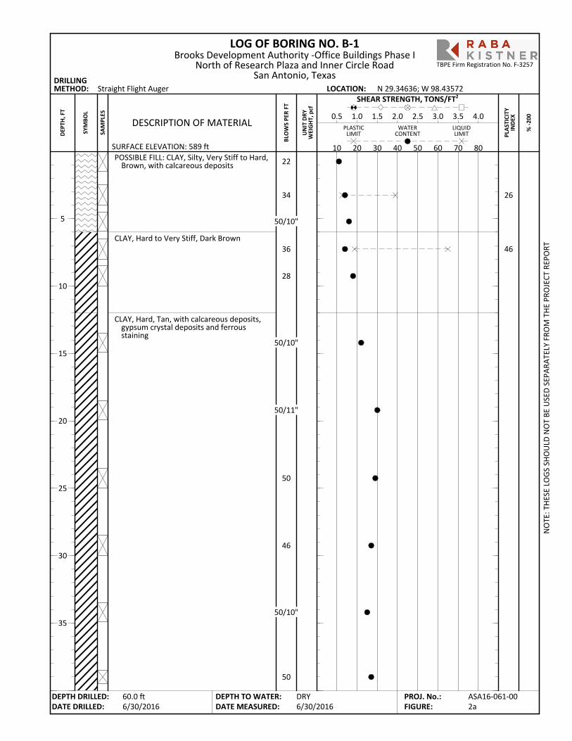
POSSIBLE FILL: CLAY, Silty, Very Stiff to Hard,Brown, with calcareous deposits
CLAY, Hard to Very Stiff, Dark Brown
CLAY, Hard, Tan, with calcareous deposits,gypsum crystal deposits and ferrousstaining
26
46
LOG OF BORING NO. B-1
PLA
STIC
ITY
IND
EX
SURFACE ELEVATION: 589 ft
Straight Flight Auger
% -2
00
DRILLINGMETHOD: LOCATION:
PLASTICLIMIT
LIQUIDLIMIT
WATERCONTENT
BLO
WS
PER
FT
10 20 30 40 50 60 70 80
DESCRIPTION OF MATERIAL0.5 1.0 1.5 2.0 2.5 3.0 3.5 4.0
SHEAR STRENGTH, TONS/FT2
UN
IT D
RYW
EIG
HT,
pcf
N 29.34636; W 98.43572
NO
TE: T
HES
E LO
GS
SHO
ULD
NO
T BE
USE
D S
EPAR
ATEL
Y FR
OM
TH
E PR
OJE
CT R
EPO
RT
DEPTH DRILLED:DATE DRILLED:
DEPTH TO WATER:DATE MEASURED:
5
10
15
20
25
30
35
SYM
BOL
SAM
PLES
Brooks Development Authority -Office Buildings Phase INorth of Research Plaza and Inner Circle Road
San Antonio, Texas
DRY6/30/2016
DEP
TH, F
T
60.0 ft6/30/2016
ASA16-061-002a
PROJ. No.:FIGURE:
TBPE Firm Registration No. F-3257
22
34
50/10"
36
28
50/10"
50/11"
50
46
50/10"
50

CLAY, Hard, Tan, with calcareous deposits,gypsum crystal deposits and ferrousstaining (continued)
- with gray shale seams from 40 ft
CLAYSHALE, Hard, Gray
Boring Terminated
LOG OF BORING NO. B-1
PLA
STIC
ITY
IND
EX
SURFACE ELEVATION: 589 ft
Straight Flight Auger
% -2
00
DRILLINGMETHOD: LOCATION:
PLASTICLIMIT
LIQUIDLIMIT
WATERCONTENT
BLO
WS
PER
FT
10 20 30 40 50 60 70 80
DESCRIPTION OF MATERIAL0.5 1.0 1.5 2.0 2.5 3.0 3.5 4.0
SHEAR STRENGTH, TONS/FT2
UN
IT D
RYW
EIG
HT,
pcf
N 29.34636; W 98.43572
NO
TE: T
HES
E LO
GS
SHO
ULD
NO
T BE
USE
D S
EPAR
ATEL
Y FR
OM
TH
E PR
OJE
CT R
EPO
RT
DEPTH DRILLED:DATE DRILLED:
DEPTH TO WATER:DATE MEASURED:
45
50
55
60
65
70
75
SYM
BOL
SAM
PLES
Brooks Development Authority -Office Buildings Phase INorth of Research Plaza and Inner Circle Road
San Antonio, Texas
DRY6/30/2016
DEP
TH, F
T
60.0 ft6/30/2016
ASA16-061-002b
PROJ. No.:FIGURE:
TBPE Firm Registration No. F-3257
ref/2"
ref/5"
100/0.25"
100/0"
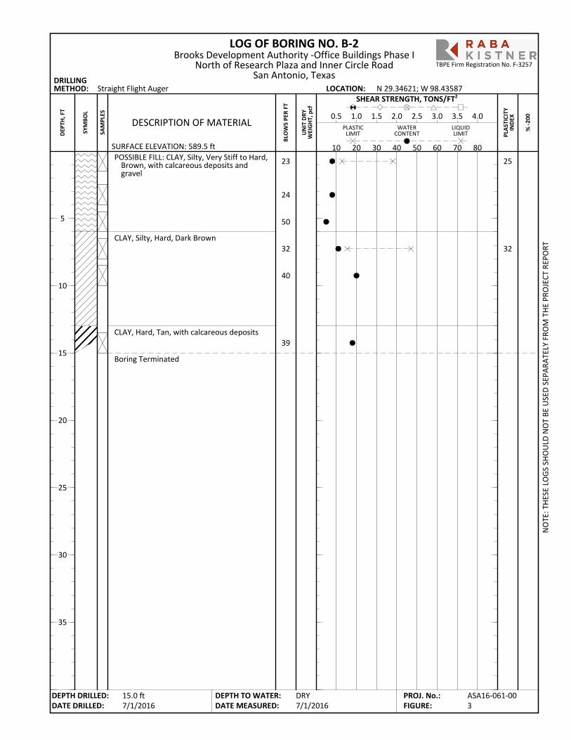
POSSIBLE FILL: CLAY, Silty, Very Stiff to Hard,Brown, with calcareous deposits andgravel
CLAY, Silty, Hard, Dark Brown
CLAY, Hard, Tan, with calcareous deposits
Boring Terminated
25
32
LOG OF BORING NO. B-2
PLA
STIC
ITY
IND
EX
SURFACE ELEVATION: 589.5 ft
Straight Flight Auger
% -2
00
DRILLINGMETHOD: LOCATION:
PLASTICLIMIT
LIQUIDLIMIT
WATERCONTENT
BLO
WS
PER
FT
10 20 30 40 50 60 70 80
DESCRIPTION OF MATERIAL0.5 1.0 1.5 2.0 2.5 3.0 3.5 4.0
SHEAR STRENGTH, TONS/FT2
UN
IT D
RYW
EIG
HT,
pcf
N 29.34621; W 98.43587
NO
TE: T
HES
E LO
GS
SHO
ULD
NO
T BE
USE
D S
EPAR
ATEL
Y FR
OM
TH
E PR
OJE
CT R
EPO
RT
DEPTH DRILLED:DATE DRILLED:
DEPTH TO WATER:DATE MEASURED:
5
10
15
20
25
30
35
SYM
BOL
SAM
PLES
Brooks Development Authority -Office Buildings Phase INorth of Research Plaza and Inner Circle Road
San Antonio, Texas
DRY7/1/2016
DEP
TH, F
T
15.0 ft7/1/2016
ASA16-061-003
PROJ. No.:FIGURE:
TBPE Firm Registration No. F-3257
23
24
50
32
40
39
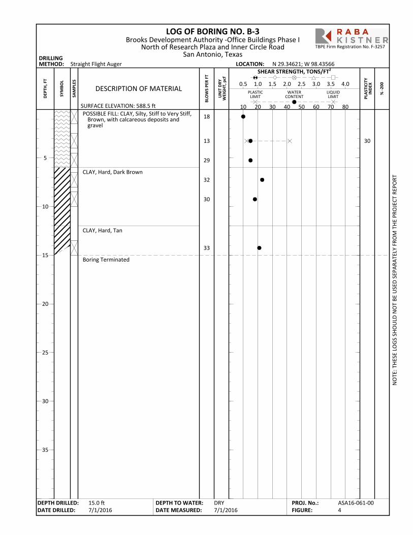
POSSIBLE FILL: CLAY, Silty, Stiff to Very Stiff,Brown, with calcareous deposits andgravel
CLAY, Hard, Dark Brown
CLAY, Hard, Tan
Boring Terminated
30
LOG OF BORING NO. B-3
PLA
STIC
ITY
IND
EX
SURFACE ELEVATION: 588.5 ft
Straight Flight Auger
% -2
00
DRILLINGMETHOD: LOCATION:
PLASTICLIMIT
LIQUIDLIMIT
WATERCONTENT
BLO
WS
PER
FT
10 20 30 40 50 60 70 80
DESCRIPTION OF MATERIAL0.5 1.0 1.5 2.0 2.5 3.0 3.5 4.0
SHEAR STRENGTH, TONS/FT2
UN
IT D
RYW
EIG
HT,
pcf
N 29.34621; W 98.43566
NO
TE: T
HES
E LO
GS
SHO
ULD
NO
T BE
USE
D S
EPAR
ATEL
Y FR
OM
TH
E PR
OJE
CT R
EPO
RT
DEPTH DRILLED:DATE DRILLED:
DEPTH TO WATER:DATE MEASURED:
5
10
15
20
25
30
35
SYM
BOL
SAM
PLES
Brooks Development Authority -Office Buildings Phase INorth of Research Plaza and Inner Circle Road
San Antonio, Texas
DRY7/1/2016
DEP
TH, F
T
15.0 ft7/1/2016
ASA16-061-004
PROJ. No.:FIGURE:
TBPE Firm Registration No. F-3257
18
13
29
32
30
33
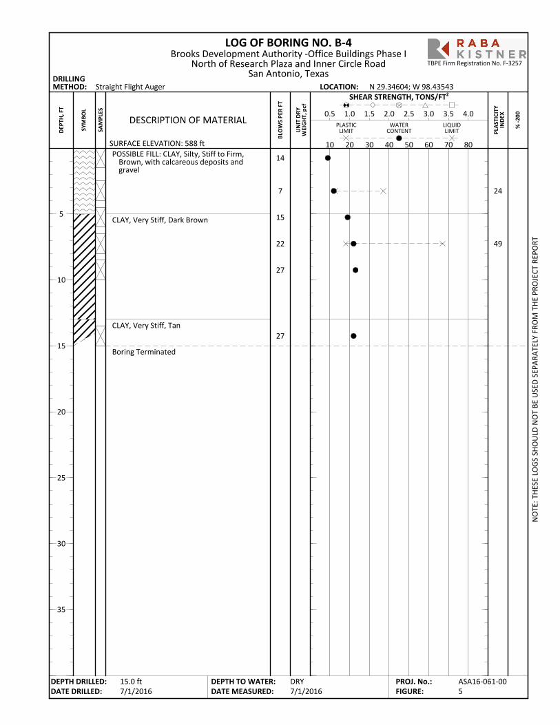
POSSIBLE FILL: CLAY, Silty, Stiff to Firm,Brown, with calcareous deposits andgravel
CLAY, Very Stiff, Dark Brown
CLAY, Very Stiff, Tan
Boring Terminated
24
49
LOG OF BORING NO. B-4
PLA
STIC
ITY
IND
EX
SURFACE ELEVATION: 588 ft
Straight Flight Auger
% -2
00
DRILLINGMETHOD: LOCATION:
PLASTICLIMIT
LIQUIDLIMIT
WATERCONTENT
BLO
WS
PER
FT
10 20 30 40 50 60 70 80
DESCRIPTION OF MATERIAL0.5 1.0 1.5 2.0 2.5 3.0 3.5 4.0
SHEAR STRENGTH, TONS/FT2
UN
IT D
RYW
EIG
HT,
pcf
N 29.34604; W 98.43543
NO
TE: T
HES
E LO
GS
SHO
ULD
NO
T BE
USE
D S
EPAR
ATEL
Y FR
OM
TH
E PR
OJE
CT R
EPO
RT
DEPTH DRILLED:DATE DRILLED:
DEPTH TO WATER:DATE MEASURED:
5
10
15
20
25
30
35
SYM
BOL
SAM
PLES
Brooks Development Authority -Office Buildings Phase INorth of Research Plaza and Inner Circle Road
San Antonio, Texas
DRY7/1/2016
DEP
TH, F
T
15.0 ft7/1/2016
ASA16-061-005
PROJ. No.:FIGURE:
TBPE Firm Registration No. F-3257
14
7
15
22
27
27
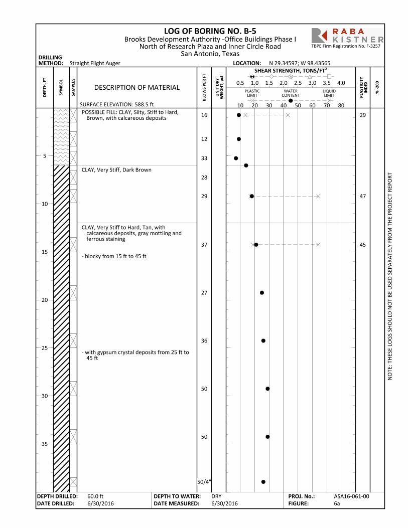
POSSIBLE FILL: CLAY, Silty, Stiff to Hard,Brown, with calcareous deposits
CLAY, Very Stiff, Dark Brown
CLAY, Very Stiff to Hard, Tan, withcalcareous deposits, gray mottling andferrous staining
- blocky from 15 ft to 45 ft
- with gypsum crystal deposits from 25 ft to45 ft
29
47
45
LOG OF BORING NO. B-5
PLA
STIC
ITY
IND
EX
SURFACE ELEVATION: 588.5 ft
Straight Flight Auger
% -2
00
DRILLINGMETHOD: LOCATION:
PLASTICLIMIT
LIQUIDLIMIT
WATERCONTENT
BLO
WS
PER
FT
10 20 30 40 50 60 70 80
DESCRIPTION OF MATERIAL0.5 1.0 1.5 2.0 2.5 3.0 3.5 4.0
SHEAR STRENGTH, TONS/FT2
UN
IT D
RYW
EIG
HT,
pcf
N 29.34597; W 98.43565
NO
TE: T
HES
E LO
GS
SHO
ULD
NO
T BE
USE
D S
EPAR
ATEL
Y FR
OM
TH
E PR
OJE
CT R
EPO
RT
DEPTH DRILLED:DATE DRILLED:
DEPTH TO WATER:DATE MEASURED:
5
10
15
20
25
30
35
SYM
BOL
SAM
PLES
Brooks Development Authority -Office Buildings Phase INorth of Research Plaza and Inner Circle Road
San Antonio, Texas
DRY6/30/2016
DEP
TH, F
T
60.0 ft6/30/2016
ASA16-061-006a
PROJ. No.:FIGURE:
TBPE Firm Registration No. F-3257
16
12
33
28
29
37
27
36
50
50
50/4"
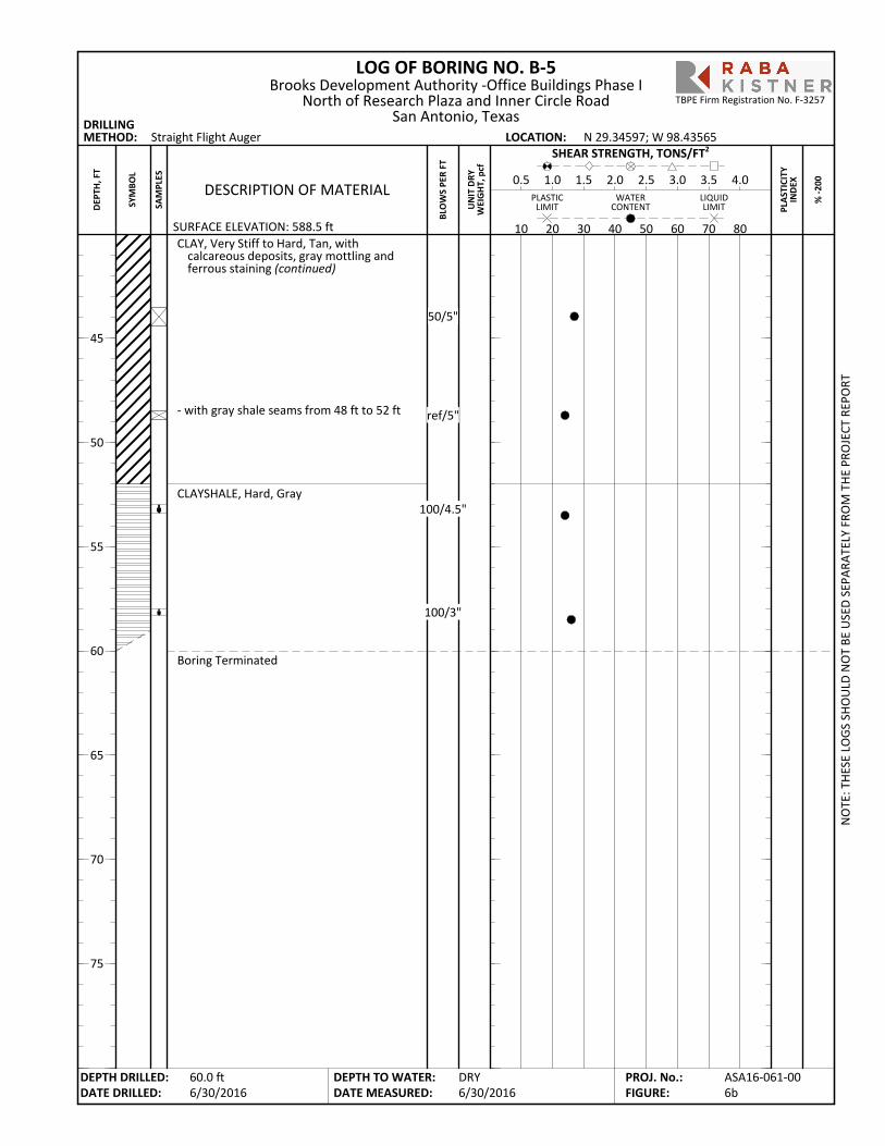
CLAY, Very Stiff to Hard, Tan, withcalcareous deposits, gray mottling andferrous staining (continued)
- with gray shale seams from 48 ft to 52 ft
CLAYSHALE, Hard, Gray
Boring Terminated
LOG OF BORING NO. B-5
PLA
STIC
ITY
IND
EX
SURFACE ELEVATION: 588.5 ft
Straight Flight Auger
% -2
00
DRILLINGMETHOD: LOCATION:
PLASTICLIMIT
LIQUIDLIMIT
WATERCONTENT
BLO
WS
PER
FT
10 20 30 40 50 60 70 80
DESCRIPTION OF MATERIAL0.5 1.0 1.5 2.0 2.5 3.0 3.5 4.0
SHEAR STRENGTH, TONS/FT2
UN
IT D
RYW
EIG
HT,
pcf
N 29.34597; W 98.43565
NO
TE: T
HES
E LO
GS
SHO
ULD
NO
T BE
USE
D S
EPAR
ATEL
Y FR
OM
TH
E PR
OJE
CT R
EPO
RT
DEPTH DRILLED:DATE DRILLED:
DEPTH TO WATER:DATE MEASURED:
45
50
55
60
65
70
75
SYM
BOL
SAM
PLES
Brooks Development Authority -Office Buildings Phase INorth of Research Plaza and Inner Circle Road
San Antonio, Texas
DRY6/30/2016
DEP
TH, F
T
60.0 ft6/30/2016
ASA16-061-006b
PROJ. No.:FIGURE:
TBPE Firm Registration No. F-3257
50/5"
ref/5"
100/4.5"
100/3"

POSSIBLE FILL: CLAY, Silty, Stiff to Very Stiff,Brown, with calcareous deposits andgravel
CLAY, Silty, Stiff to Very Stiff, Dark Brown
CLAY, Hard, Tan
Boring Terminated
33
LOG OF BORING NO. B-6
PLA
STIC
ITY
IND
EX
SURFACE ELEVATION: 588 ft
Straight Flight Auger
% -2
00
DRILLINGMETHOD: LOCATION:
PLASTICLIMIT
LIQUIDLIMIT
WATERCONTENT
BLO
WS
PER
FT
10 20 30 40 50 60 70 80
DESCRIPTION OF MATERIAL0.5 1.0 1.5 2.0 2.5 3.0 3.5 4.0
SHEAR STRENGTH, TONS/FT2
UN
IT D
RYW
EIG
HT,
pcf
N 29.34568; W 98.43566
NO
TE: T
HES
E LO
GS
SHO
ULD
NO
T BE
USE
D S
EPAR
ATEL
Y FR
OM
TH
E PR
OJE
CT R
EPO
RT
DEPTH DRILLED:DATE DRILLED:
DEPTH TO WATER:DATE MEASURED:
5
10
15
20
25
30
35
SYM
BOL
SAM
PLES
Brooks Development Authority -Office Buildings Phase INorth of Research Plaza and Inner Circle Road
San Antonio, Texas
DRY7/1/2016
DEP
TH, F
T
15.0 ft7/1/2016
ASA16-061-007
PROJ. No.:FIGURE:
TBPE Firm Registration No. F-3257
12
22
21
31
21
31

POSSIBLE FILL: CLAY, Silty, Very Stiff to Hard,Brown, with calcareous deposits andgravel
CLAY, Silty, Hard to Very Stiff, Dark Brown
CLAY, Very Stiff, Tan
Boring Terminated
32
LOG OF BORING NO. B-7
PLA
STIC
ITY
IND
EX
SURFACE ELEVATION: 588 ft
Straight Flight Auger
% -2
00
DRILLINGMETHOD: LOCATION:
PLASTICLIMIT
LIQUIDLIMIT
WATERCONTENT
BLO
WS
PER
FT
10 20 30 40 50 60 70 80
DESCRIPTION OF MATERIAL0.5 1.0 1.5 2.0 2.5 3.0 3.5 4.0
SHEAR STRENGTH, TONS/FT2
UN
IT D
RYW
EIG
HT,
pcf
N 29.34554; W 98.43581
NO
TE: T
HES
E LO
GS
SHO
ULD
NO
T BE
USE
D S
EPAR
ATEL
Y FR
OM
TH
E PR
OJE
CT R
EPO
RT
DEPTH DRILLED:DATE DRILLED:
DEPTH TO WATER:DATE MEASURED:
5
10
15
20
25
30
35
SYM
BOL
SAM
PLES
Brooks Development Authority -Office Buildings Phase INorth of Research Plaza and Inner Circle Road
San Antonio, Texas
DRY7/1/2016
DEP
TH, F
T
15.0 ft7/1/2016
ASA16-061-008
PROJ. No.:FIGURE:
TBPE Firm Registration No. F-3257
16
36
44
35
19
27
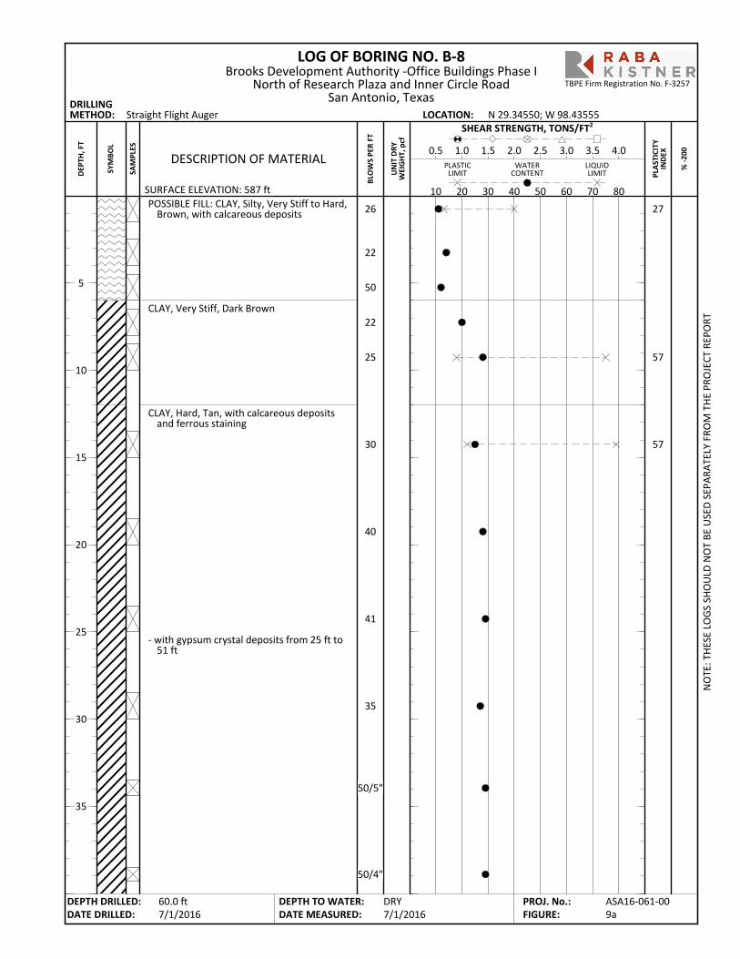
POSSIBLE FILL: CLAY, Silty, Very Stiff to Hard,Brown, with calcareous deposits
CLAY, Very Stiff, Dark Brown
CLAY, Hard, Tan, with calcareous depositsand ferrous staining
- with gypsum crystal deposits from 25 ft to51 ft
27
57
57
LOG OF BORING NO. B-8
PLA
STIC
ITY
IND
EX
SURFACE ELEVATION: 587 ft
Straight Flight Auger
% -2
00
DRILLINGMETHOD: LOCATION:
PLASTICLIMIT
LIQUIDLIMIT
WATERCONTENT
BLO
WS
PER
FT
10 20 30 40 50 60 70 80
DESCRIPTION OF MATERIAL0.5 1.0 1.5 2.0 2.5 3.0 3.5 4.0
SHEAR STRENGTH, TONS/FT2
UN
IT D
RYW
EIG
HT,
pcf
N 29.34550; W 98.43555
NO
TE: T
HES
E LO
GS
SHO
ULD
NO
T BE
USE
D S
EPAR
ATEL
Y FR
OM
TH
E PR
OJE
CT R
EPO
RT
DEPTH DRILLED:DATE DRILLED:
DEPTH TO WATER:DATE MEASURED:
5
10
15
20
25
30
35
SYM
BOL
SAM
PLES
Brooks Development Authority -Office Buildings Phase INorth of Research Plaza and Inner Circle Road
San Antonio, Texas
DRY7/1/2016
DEP
TH, F
T
60.0 ft7/1/2016
ASA16-061-009a
PROJ. No.:FIGURE:
TBPE Firm Registration No. F-3257
26
22
50
22
25
30
40
41
35
50/5"
50/4"
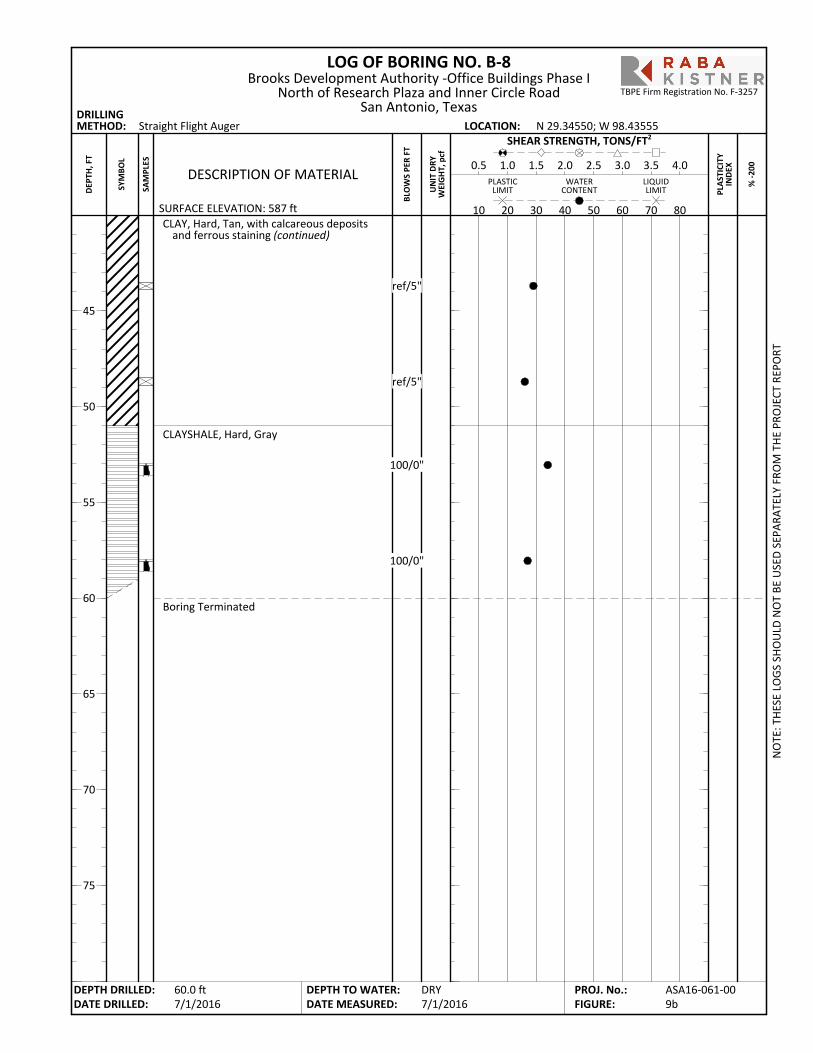
CLAY, Hard, Tan, with calcareous depositsand ferrous staining (continued)
CLAYSHALE, Hard, Gray
Boring Terminated
LOG OF BORING NO. B-8
PLA
STIC
ITY
IND
EX
SURFACE ELEVATION: 587 ft
Straight Flight Auger
% -2
00
DRILLINGMETHOD: LOCATION:
PLASTICLIMIT
LIQUIDLIMIT
WATERCONTENT
BLO
WS
PER
FT
10 20 30 40 50 60 70 80
DESCRIPTION OF MATERIAL0.5 1.0 1.5 2.0 2.5 3.0 3.5 4.0
SHEAR STRENGTH, TONS/FT2
UN
IT D
RYW
EIG
HT,
pcf
N 29.34550; W 98.43555
NO
TE: T
HES
E LO
GS
SHO
ULD
NO
T BE
USE
D S
EPAR
ATEL
Y FR
OM
TH
E PR
OJE
CT R
EPO
RT
DEPTH DRILLED:DATE DRILLED:
DEPTH TO WATER:DATE MEASURED:
45
50
55
60
65
70
75
SYM
BOL
SAM
PLES
Brooks Development Authority -Office Buildings Phase INorth of Research Plaza and Inner Circle Road
San Antonio, Texas
DRY7/1/2016
DEP
TH, F
T
60.0 ft7/1/2016
ASA16-061-009b
PROJ. No.:FIGURE:
TBPE Firm Registration No. F-3257
ref/5"
ref/5"
100/0"
100/0"

POSSIBLE FILL: CLAY, Silty, Very Stiff, Brown,with calcareous deposits
Boring Terminated
LOG OF BORING NO. P-1
PLA
STIC
ITY
IND
EX
SURFACE ELEVATION: 586.5 ft
Straight Flight Auger
% -2
00
DRILLINGMETHOD: LOCATION:
PLASTICLIMIT
LIQUIDLIMIT
WATERCONTENT
BLO
WS
PER
FT
10 20 30 40 50 60 70 80
DESCRIPTION OF MATERIAL0.5 1.0 1.5 2.0 2.5 3.0 3.5 4.0
SHEAR STRENGTH, TONS/FT2
UN
IT D
RYW
EIG
HT,
pcf
N 29.34546; W 98.43519
NO
TE: T
HES
E LO
GS
SHO
ULD
NO
T BE
USE
D S
EPAR
ATEL
Y FR
OM
TH
E PR
OJE
CT R
EPO
RT
DEPTH DRILLED:DATE DRILLED:
DEPTH TO WATER:DATE MEASURED:
5
10
15
20
25
30
35
SYM
BOL
SAM
PLES
Brooks Development Authority -Office Buildings Phase INorth of Research Plaza and Inner Circle Road
San Antonio, Texas
DRY7/1/2016
DEP
TH, F
T
5.0 ft7/1/2016
ASA16-061-0010
PROJ. No.:FIGURE:
TBPE Firm Registration No. F-3257
18
21
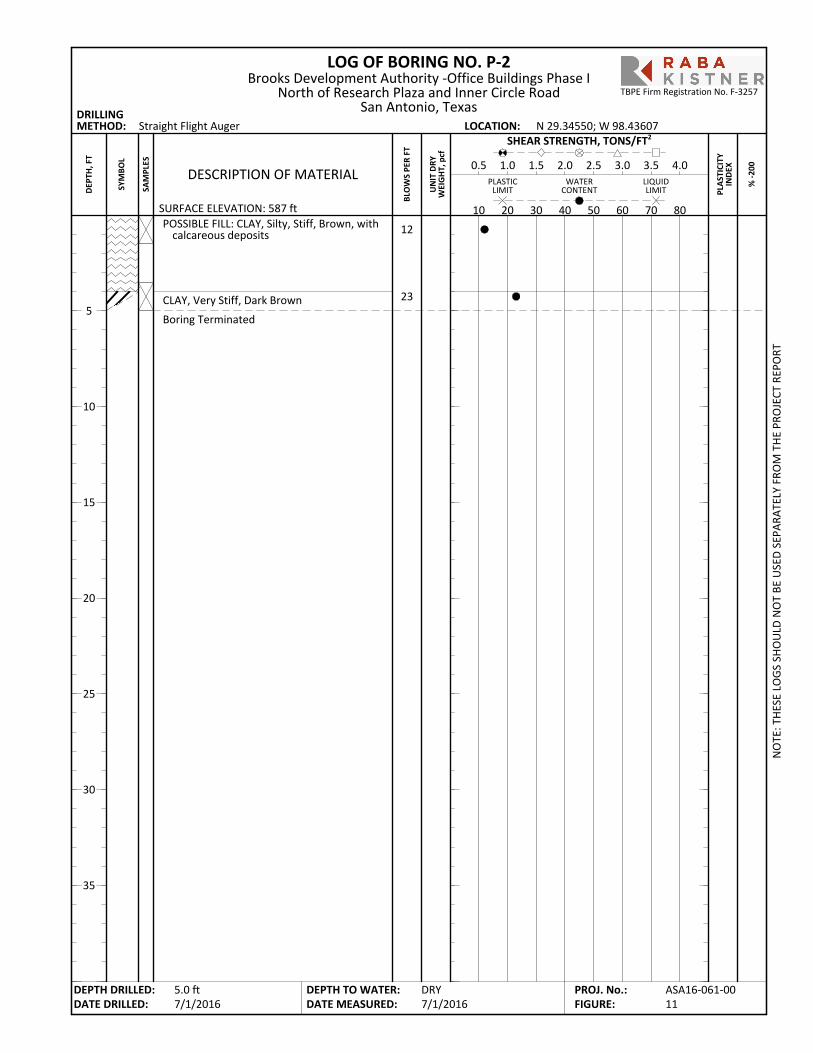
POSSIBLE FILL: CLAY, Silty, Stiff, Brown, withcalcareous deposits
CLAY, Very Stiff, Dark Brown
Boring Terminated
LOG OF BORING NO. P-2
PLA
STIC
ITY
IND
EX
SURFACE ELEVATION: 587 ft
Straight Flight Auger
% -2
00
DRILLINGMETHOD: LOCATION:
PLASTICLIMIT
LIQUIDLIMIT
WATERCONTENT
BLO
WS
PER
FT
10 20 30 40 50 60 70 80
DESCRIPTION OF MATERIAL0.5 1.0 1.5 2.0 2.5 3.0 3.5 4.0
SHEAR STRENGTH, TONS/FT2
UN
IT D
RYW
EIG
HT,
pcf
N 29.34550; W 98.43607
NO
TE: T
HES
E LO
GS
SHO
ULD
NO
T BE
USE
D S
EPAR
ATEL
Y FR
OM
TH
E PR
OJE
CT R
EPO
RT
DEPTH DRILLED:DATE DRILLED:
DEPTH TO WATER:DATE MEASURED:
5
10
15
20
25
30
35
SYM
BOL
SAM
PLES
Brooks Development Authority -Office Buildings Phase INorth of Research Plaza and Inner Circle Road
San Antonio, Texas
DRY7/1/2016
DEP
TH, F
T
5.0 ft7/1/2016
ASA16-061-0011
PROJ. No.:FIGURE:
TBPE Firm Registration No. F-3257
12
23
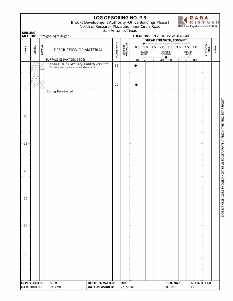
POSSIBLE FILL: CLAY, Silty, Hard to Very Stiff,Brown, with calcareous deposits
Boring Terminated
LOG OF BORING NO. P-3
PLA
STIC
ITY
IND
EX
SURFACE ELEVATION: 590 ft
Straight Flight Auger
% -2
00
DRILLINGMETHOD: LOCATION:
PLASTICLIMIT
LIQUIDLIMIT
WATERCONTENT
BLO
WS
PER
FT
10 20 30 40 50 60 70 80
DESCRIPTION OF MATERIAL0.5 1.0 1.5 2.0 2.5 3.0 3.5 4.0
SHEAR STRENGTH, TONS/FT2
UN
IT D
RYW
EIG
HT,
pcf
N 29.34615; W 98.43648
NO
TE: T
HES
E LO
GS
SHO
ULD
NO
T BE
USE
D S
EPAR
ATEL
Y FR
OM
TH
E PR
OJE
CT R
EPO
RT
DEPTH DRILLED:DATE DRILLED:
DEPTH TO WATER:DATE MEASURED:
5
10
15
20
25
30
35
SYM
BOL
SAM
PLES
Brooks Development Authority -Office Buildings Phase INorth of Research Plaza and Inner Circle Road
San Antonio, Texas
DRY7/1/2016
DEP
TH, F
T
5.0 ft7/1/2016
ASA16-061-0012
PROJ. No.:FIGURE:
TBPE Firm Registration No. F-3257
39
27

POSSIBLE FILL: CLAY, Silty, Very Stiff, Brown,with calcareous deposits
Boring Terminated
LOG OF BORING NO. P-4
PLA
STIC
ITY
IND
EX
SURFACE ELEVATION: 592.5 ft
Straight Flight Auger
% -2
00
DRILLINGMETHOD: LOCATION:
PLASTICLIMIT
LIQUIDLIMIT
WATERCONTENT
BLO
WS
PER
FT
10 20 30 40 50 60 70 80
DESCRIPTION OF MATERIAL0.5 1.0 1.5 2.0 2.5 3.0 3.5 4.0
SHEAR STRENGTH, TONS/FT2
UN
IT D
RYW
EIG
HT,
pcf
N 29.34644; W 98.43700
NO
TE: T
HES
E LO
GS
SHO
ULD
NO
T BE
USE
D S
EPAR
ATEL
Y FR
OM
TH
E PR
OJE
CT R
EPO
RT
DEPTH DRILLED:DATE DRILLED:
DEPTH TO WATER:DATE MEASURED:
5
10
15
20
25
30
35
SYM
BOL
SAM
PLES
Brooks Development Authority -Office Buildings Phase INorth of Research Plaza and Inner Circle Road
San Antonio, Texas
DRY7/1/2016
DEP
TH, F
T
5.0 ft7/1/2016
ASA16-061-0013
PROJ. No.:FIGURE:
TBPE Firm Registration No. F-3257
16
20
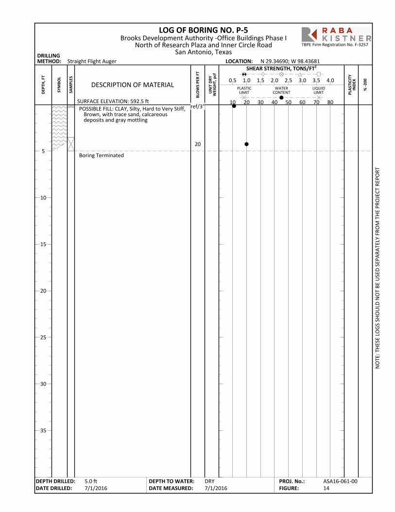
POSSIBLE FILL: CLAY, Silty, Hard to Very Stiff,Brown, with trace sand, calcareousdeposits and gray mottling
Boring Terminated
LOG OF BORING NO. P-5
PLA
STIC
ITY
IND
EX
SURFACE ELEVATION: 592.5 ft
Straight Flight Auger
% -2
00
DRILLINGMETHOD: LOCATION:
PLASTICLIMIT
LIQUIDLIMIT
WATERCONTENT
BLO
WS
PER
FT
10 20 30 40 50 60 70 80
DESCRIPTION OF MATERIAL0.5 1.0 1.5 2.0 2.5 3.0 3.5 4.0
SHEAR STRENGTH, TONS/FT2
UN
IT D
RYW
EIG
HT,
pcf
N 29.34690; W 98.43681
NO
TE: T
HES
E LO
GS
SHO
ULD
NO
T BE
USE
D S
EPAR
ATEL
Y FR
OM
TH
E PR
OJE
CT R
EPO
RT
DEPTH DRILLED:DATE DRILLED:
DEPTH TO WATER:DATE MEASURED:
5
10
15
20
25
30
35
SYM
BOL
SAM
PLES
Brooks Development Authority -Office Buildings Phase INorth of Research Plaza and Inner Circle Road
San Antonio, Texas
DRY7/1/2016
DEP
TH, F
T
5.0 ft7/1/2016
ASA16-061-0014
PROJ. No.:FIGURE:
TBPE Firm Registration No. F-3257
ref/3"
20
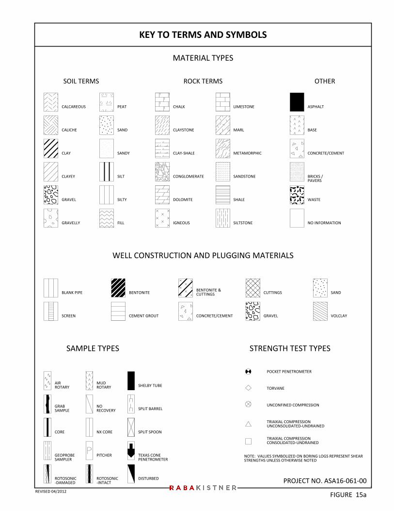
PROJECT NO. ASA16-061-00
CLAY-SHALE
SAMPLE TYPES
NO INFORMATION
BLANK PIPE
ASPHALT
IGNEOUS
LIMESTONE
FILL
GEOPROBESAMPLER
TEXAS CONEPENETROMETER
DISTURBED
METAMORPHIC
MARL
MUDROTARY
NORECOVERY SPLIT BARREL
SPLIT SPOONNX CORE
SHELBY TUBE
CALCAREOUS
CLAY
CLAYEY
GRAVEL
GRAVELLY
WELL CONSTRUCTION AND PLUGGING MATERIALS
SILTSTONE
CALICHE
CONGLOMERATE
AIRROTARY
GRABSAMPLE
DOLOMITE
BENTONITE
CORE
SOIL TERMS OTHER
NOTE: VALUES SYMBOLIZED ON BORING LOGS REPRESENT SHEARSTRENGTHS UNLESS OTHERWISE NOTED
BASE
KEY TO TERMS AND SYMBOLS
CUTTINGS
SAND
SANDY
SILT
SILTY
CHALK
STRENGTH TEST TYPES
CEMENT GROUT GRAVEL
SAND
POCKET PENETROMETER
TORVANE
UNCONFINED COMPRESSION
TRIAXIAL COMPRESSIONUNCONSOLIDATED-UNDRAINED
TRIAXIAL COMPRESSIONCONSOLIDATED-UNDRAINED
BRICKS /PAVERS
SCREEN
MATERIAL TYPES
VOLCLAY
SANDSTONE
SHALE
ROCK TERMS
WASTE
CONCRETE/CEMENT
PEAT
BENTONITE &CUTTINGS
CONCRETE/CEMENT
CLAYSTONE
ROTOSONIC-DAMAGED
ROTOSONIC-INTACT
PITCHER
FIGURE 15aREVISED 04/2012
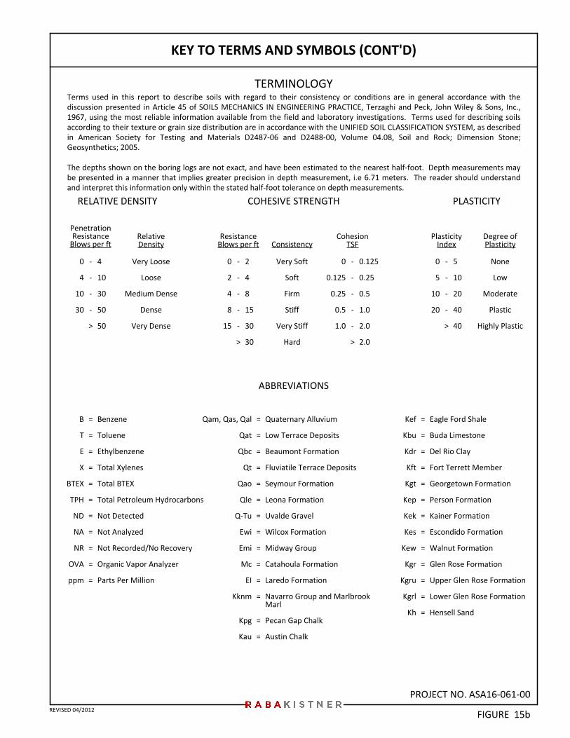
PROJECT NO. ASA16-061-00
KEY TO TERMS AND SYMBOLS (CONT'D)
TERMINOLOGY
RELATIVE DENSITY PLASTICITYCOHESIVE STRENGTH
PenetrationResistance
Blows per ftDegree ofPlasticity
PlasticityIndex
RelativeDensity
ResistanceBlows per ft
0
4
10
30
-
-
-
-
>
4
10
30
50
50
Very Loose
Loose
Medium Dense
Dense
Very Dense
ConsistencyCohesion
TSF
-
-
-
-
>
-
-
-
-
-
>
Benzene
Toluene
Ethylbenzene
Total Xylenes
Total BTEX
Total Petroleum Hydrocarbons
Not Detected
Not Analyzed
Not Recorded/No Recovery
Organic Vapor Analyzer
Parts Per Million
2
4
8
15
30
30
Very Soft
Soft
Firm
Stiff
Very Stiff
Hard
0
2
4
8
15
0
0.125
0.25
0.5
1.0
-
-
-
-
-
>
0.125
0.25
0.5
1.0
2.0
2.0
0
5
10
20
5
10
20
40
40
None
Low
Moderate
Plastic
Highly Plastic
=
=
=
=
=
=
=
=
=
=
=
ABBREVIATIONS
Qam, Qas, Qal
Qat
Qbc
Qt
Qao
Qle
Q-Tu
Ewi
Emi
Mc
EI
Kknm
Kpg
Kau
=
=
=
=
=
=
=
=
=
=
=
=
=
=
Kef
Kbu
Kdr
Kft
Kgt
Kep
Kek
Kes
Kew
Kgr
Kgru
Kgrl
Kh
Quaternary Alluvium
Low Terrace Deposits
Beaumont Formation
Fluviatile Terrace Deposits
Seymour Formation
Leona Formation
Uvalde Gravel
Wilcox Formation
Midway Group
Catahoula Formation
Laredo Formation
Navarro Group and MarlbrookMarl
Pecan Gap Chalk
Austin Chalk
=
=
=
=
=
=
=
=
=
=
=
=
=
Eagle Ford Shale
Buda Limestone
Del Rio Clay
Fort Terrett Member
Georgetown Formation
Person Formation
Kainer Formation
Escondido Formation
Walnut Formation
Glen Rose Formation
Upper Glen Rose Formation
Lower Glen Rose Formation
Hensell Sand
B
T
E
X
BTEX
TPH
ND
NA
NR
OVA
ppm
Terms used in this report to describe soils with regard to their consistency or conditions are in general accordance with thediscussion presented in Article 45 of SOILS MECHANICS IN ENGINEERING PRACTICE, Terzaghi and Peck, John Wiley & Sons, Inc.,1967, using the most reliable information available from the field and laboratory investigations. Terms used for describing soilsaccording to their texture or grain size distribution are in accordance with the UNIFIED SOIL CLASSIFICATION SYSTEM, as describedin American Society for Testing and Materials D2487-06 and D2488-00, Volume 04.08, Soil and Rock; Dimension Stone;Geosynthetics; 2005.
The depths shown on the boring logs are not exact, and have been estimated to the nearest half-foot. Depth measurements maybe presented in a manner that implies greater precision in depth measurement, i.e 6.71 meters. The reader should understandand interpret this information only within the stated half-foot tolerance on depth measurements.
FIGURE 15bREVISED 04/2012
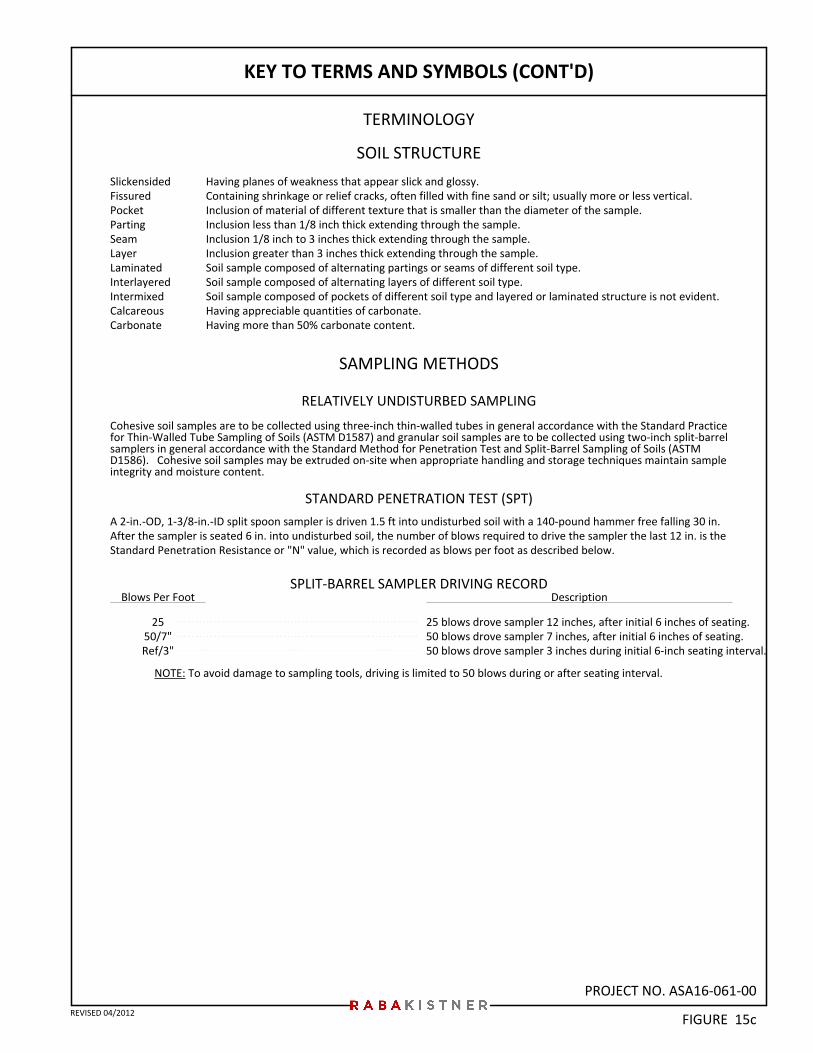
PROJECT NO. ASA16-061-00
KEY TO TERMS AND SYMBOLS (CONT'D)
TERMINOLOGY
SOIL STRUCTURE
SAMPLING METHODS
Having planes of weakness that appear slick and glossy.Containing shrinkage or relief cracks, often filled with fine sand or silt; usually more or less vertical.Inclusion of material of different texture that is smaller than the diameter of the sample.Inclusion less than 1/8 inch thick extending through the sample.Inclusion 1/8 inch to 3 inches thick extending through the sample.Inclusion greater than 3 inches thick extending through the sample.Soil sample composed of alternating partings or seams of different soil type.Soil sample composed of alternating layers of different soil type.Soil sample composed of pockets of different soil type and layered or laminated structure is not evident.Having appreciable quantities of carbonate.Having more than 50% carbonate content.
SlickensidedFissuredPocketPartingSeamLayerLaminatedInterlayeredIntermixedCalcareousCarbonate
RELATIVELY UNDISTURBED SAMPLING
NOTE: To avoid damage to sampling tools, driving is limited to 50 blows during or after seating interval.
STANDARD PENETRATION TEST (SPT)
Cohesive soil samples are to be collected using three-inch thin-walled tubes in general accordance with the Standard Practicefor Thin-Walled Tube Sampling of Soils (ASTM D1587) and granular soil samples are to be collected using two-inch split-barrelsamplers in general accordance with the Standard Method for Penetration Test and Split-Barrel Sampling of Soils (ASTMD1586). Cohesive soil samples may be extruded on-site when appropriate handling and storage techniques maintain sampleintegrity and moisture content.
Description
25 blows drove sampler 12 inches, after initial 6 inches of seating.50 blows drove sampler 7 inches, after initial 6 inches of seating.50 blows drove sampler 3 inches during initial 6-inch seating interval.
Blows Per Foot
2550/7"Ref/3"
FIGURE 15c
A 2-in.-OD, 1-3/8-in.-ID split spoon sampler is driven 1.5 ft into undisturbed soil with a 140-pound hammer free falling 30 in.After the sampler is seated 6 in. into undisturbed soil, the number of blows required to drive the sampler the last 12 in. is theStandard Penetration Resistance or "N" value, which is recorded as blows per foot as described below.
REVISED 04/2012
SPLIT-BARREL SAMPLER DRIVING RECORD
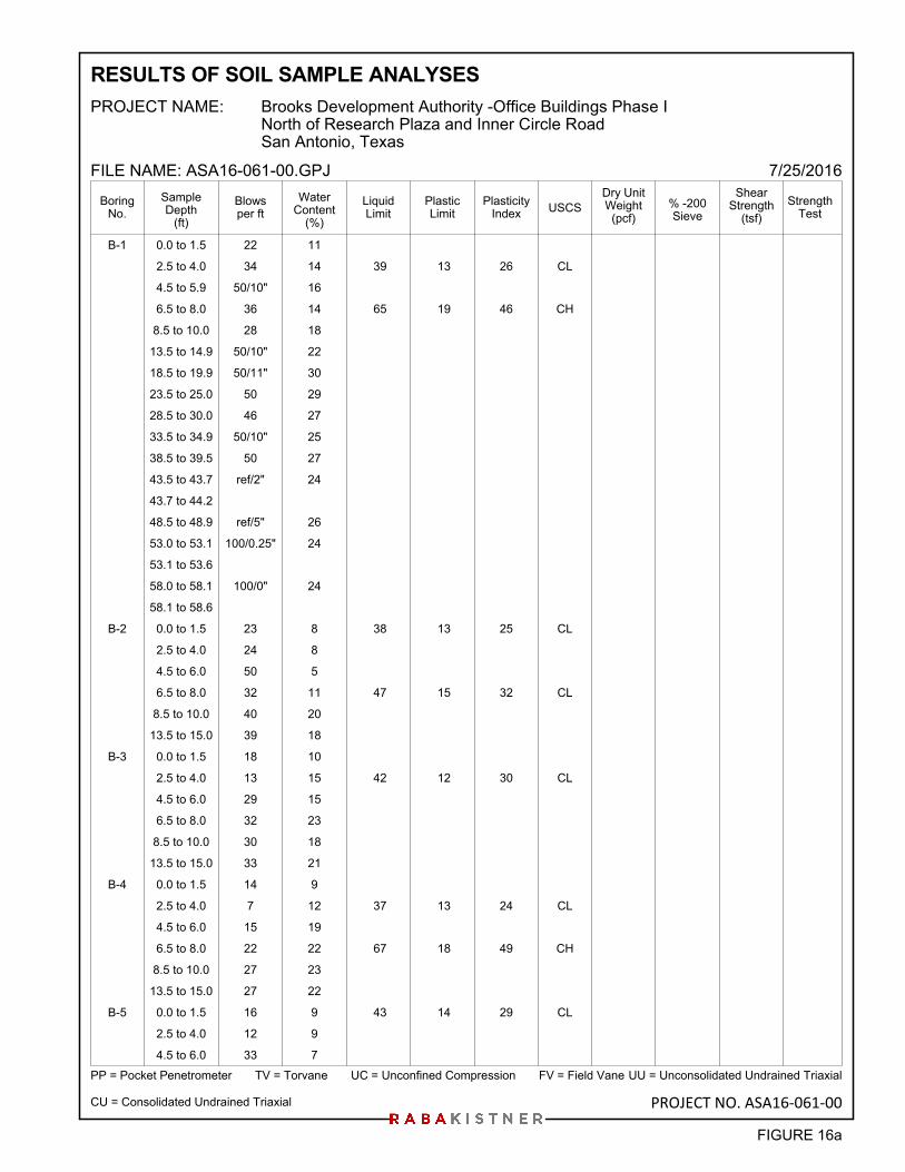
B-1 0.0 to 1.5 22 11
2.5 to 4.0 34 14 39 13 26 CL
4.5 to 5.9 50/10" 16
6.5 to 8.0 36 14 65 19 46 CH
8.5 to 10.0 28 18
13.5 to 14.9 50/10" 22
18.5 to 19.9 50/11" 30
23.5 to 25.0 50 29
28.5 to 30.0 46 27
33.5 to 34.9 50/10" 25
38.5 to 39.5 50 27
43.5 to 43.7 ref/2" 24
43.7 to 44.2
48.5 to 48.9 ref/5" 26
53.0 to 53.1 100/0.25" 24
53.1 to 53.6
58.0 to 58.1 100/0" 24
58.1 to 58.6
B-2 0.0 to 1.5 23 8 38 13 25 CL
2.5 to 4.0 24 8
4.5 to 6.0 50 5
6.5 to 8.0 32 11 47 15 32 CL
8.5 to 10.0 40 20
13.5 to 15.0 39 18
B-3 0.0 to 1.5 18 10
2.5 to 4.0 13 15 42 12 30 CL
4.5 to 6.0 29 15
6.5 to 8.0 32 23
8.5 to 10.0 30 18
13.5 to 15.0 33 21
B-4 0.0 to 1.5 14 9
2.5 to 4.0 7 12 37 13 24 CL
4.5 to 6.0 15 19
6.5 to 8.0 22 22 67 18 49 CH
8.5 to 10.0 27 23
13.5 to 15.0 27 22
B-5 0.0 to 1.5 16 9 43 14 29 CL
2.5 to 4.0 12 9
4.5 to 6.0 33 7
PlasticityIndex
LiquidLimit
PP = Pocket Penetrometer TV = Torvane UC = Unconfined Compression FV = Field Vane
PlasticLimit
WaterContent
(%)
Dry UnitWeight
(pcf)
PROJECT NAME:
FILE NAME: ASA16-061-00.GPJ
USCS % -200Sieve
ShearStrength
(tsf)
StrengthTest
BoringNo.
7/25/2016
UU = Unconsolidated Undrained Triaxial
SampleDepth
(ft)
CU = Consolidated Undrained Triaxial
Brooks Development Authority -Office Buildings Phase INorth of Research Plaza and Inner Circle RoadSan Antonio, Texas
RESULTS OF SOIL SAMPLE ANALYSES
Blowsper ft
FIGURE 16a
PROJECT NO. ASA16-061-00
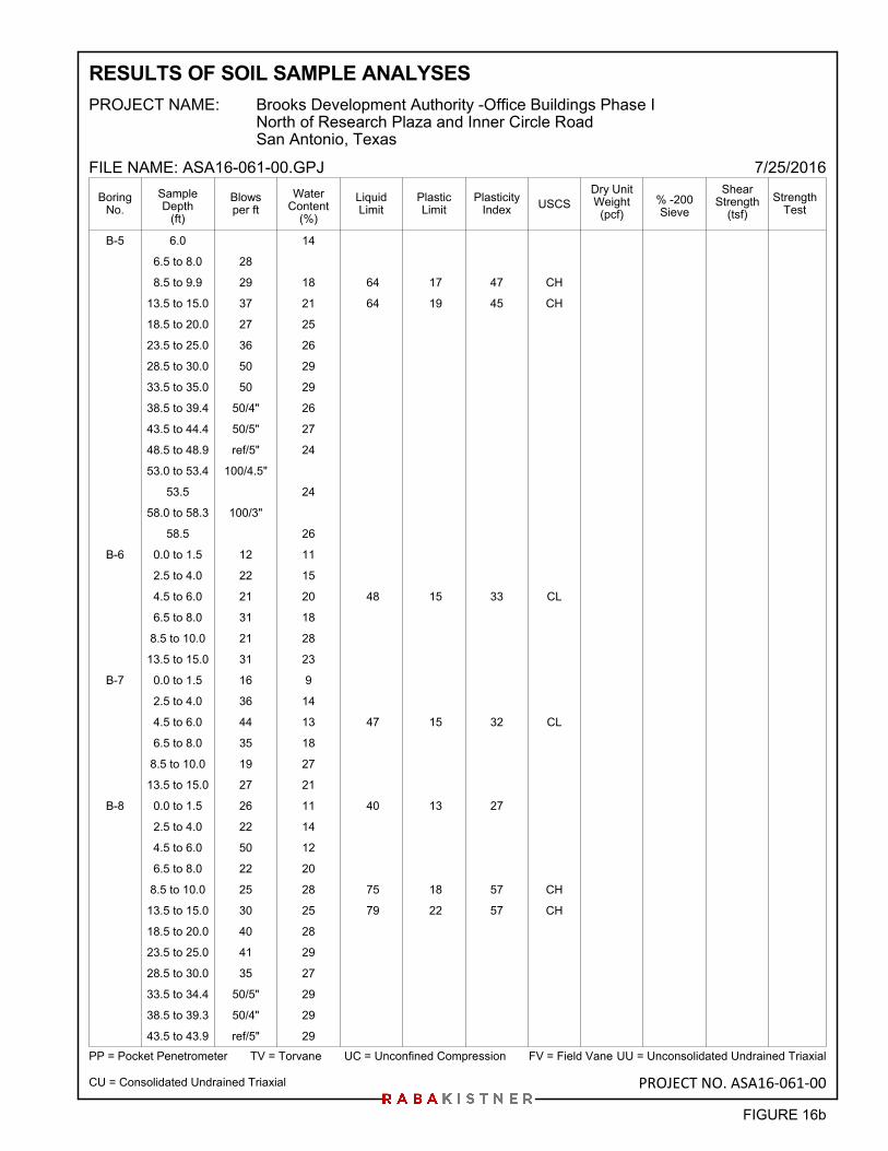
B-5 6.0 14
6.5 to 8.0 28
8.5 to 9.9 29 18 64 17 47 CH
13.5 to 15.0 37 21 64 19 45 CH
18.5 to 20.0 27 25
23.5 to 25.0 36 26
28.5 to 30.0 50 29
33.5 to 35.0 50 29
38.5 to 39.4 50/4" 26
43.5 to 44.4 50/5" 27
48.5 to 48.9 ref/5" 24
53.0 to 53.4 100/4.5"
53.5 24
58.0 to 58.3 100/3"
58.5 26
B-6 0.0 to 1.5 12 11
2.5 to 4.0 22 15
4.5 to 6.0 21 20 48 15 33 CL
6.5 to 8.0 31 18
8.5 to 10.0 21 28
13.5 to 15.0 31 23
B-7 0.0 to 1.5 16 9
2.5 to 4.0 36 14
4.5 to 6.0 44 13 47 15 32 CL
6.5 to 8.0 35 18
8.5 to 10.0 19 27
13.5 to 15.0 27 21
B-8 0.0 to 1.5 26 11 40 13 27
2.5 to 4.0 22 14
4.5 to 6.0 50 12
6.5 to 8.0 22 20
8.5 to 10.0 25 28 75 18 57 CH
13.5 to 15.0 30 25 79 22 57 CH
18.5 to 20.0 40 28
23.5 to 25.0 41 29
28.5 to 30.0 35 27
33.5 to 34.4 50/5" 29
38.5 to 39.3 50/4" 29
43.5 to 43.9 ref/5" 29
PlasticityIndex
LiquidLimit
PP = Pocket Penetrometer TV = Torvane UC = Unconfined Compression FV = Field Vane
PlasticLimit
WaterContent
(%)
Dry UnitWeight
(pcf)
PROJECT NAME:
FILE NAME: ASA16-061-00.GPJ
USCS % -200Sieve
ShearStrength
(tsf)
StrengthTest
BoringNo.
7/25/2016
UU = Unconsolidated Undrained Triaxial
SampleDepth
(ft)
CU = Consolidated Undrained Triaxial
Brooks Development Authority -Office Buildings Phase INorth of Research Plaza and Inner Circle RoadSan Antonio, Texas
RESULTS OF SOIL SAMPLE ANALYSES
Blowsper ft
FIGURE 16b
PROJECT NO. ASA16-061-00
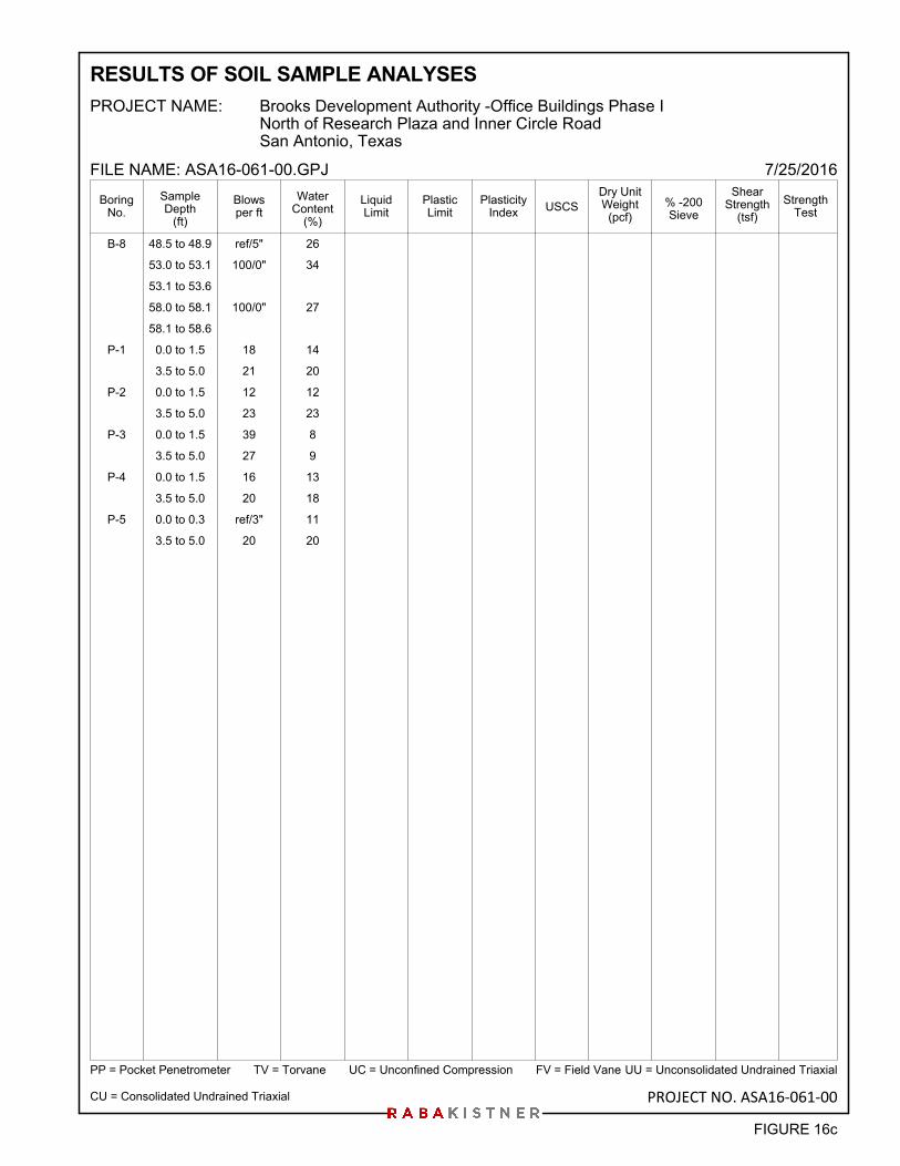
B-8 48.5 to 48.9 ref/5" 26
53.0 to 53.1 100/0" 34
53.1 to 53.6
58.0 to 58.1 100/0" 27
58.1 to 58.6
P-1 0.0 to 1.5 18 14
3.5 to 5.0 21 20
P-2 0.0 to 1.5 12 12
3.5 to 5.0 23 23
P-3 0.0 to 1.5 39 8
3.5 to 5.0 27 9
P-4 0.0 to 1.5 16 13
3.5 to 5.0 20 18
P-5 0.0 to 0.3 ref/3" 11
3.5 to 5.0 20 20
PlasticityIndex
LiquidLimit
PP = Pocket Penetrometer TV = Torvane UC = Unconfined Compression FV = Field Vane
PlasticLimit
WaterContent
(%)
Dry UnitWeight
(pcf)
PROJECT NAME:
FILE NAME: ASA16-061-00.GPJ
USCS % -200Sieve
ShearStrength
(tsf)
StrengthTest
BoringNo.
7/25/2016
UU = Unconsolidated Undrained Triaxial
SampleDepth
(ft)
CU = Consolidated Undrained Triaxial
Brooks Development Authority -Office Buildings Phase INorth of Research Plaza and Inner Circle RoadSan Antonio, Texas
RESULTS OF SOIL SAMPLE ANALYSES
Blowsper ft
FIGURE 16c
PROJECT NO. ASA16-061-00
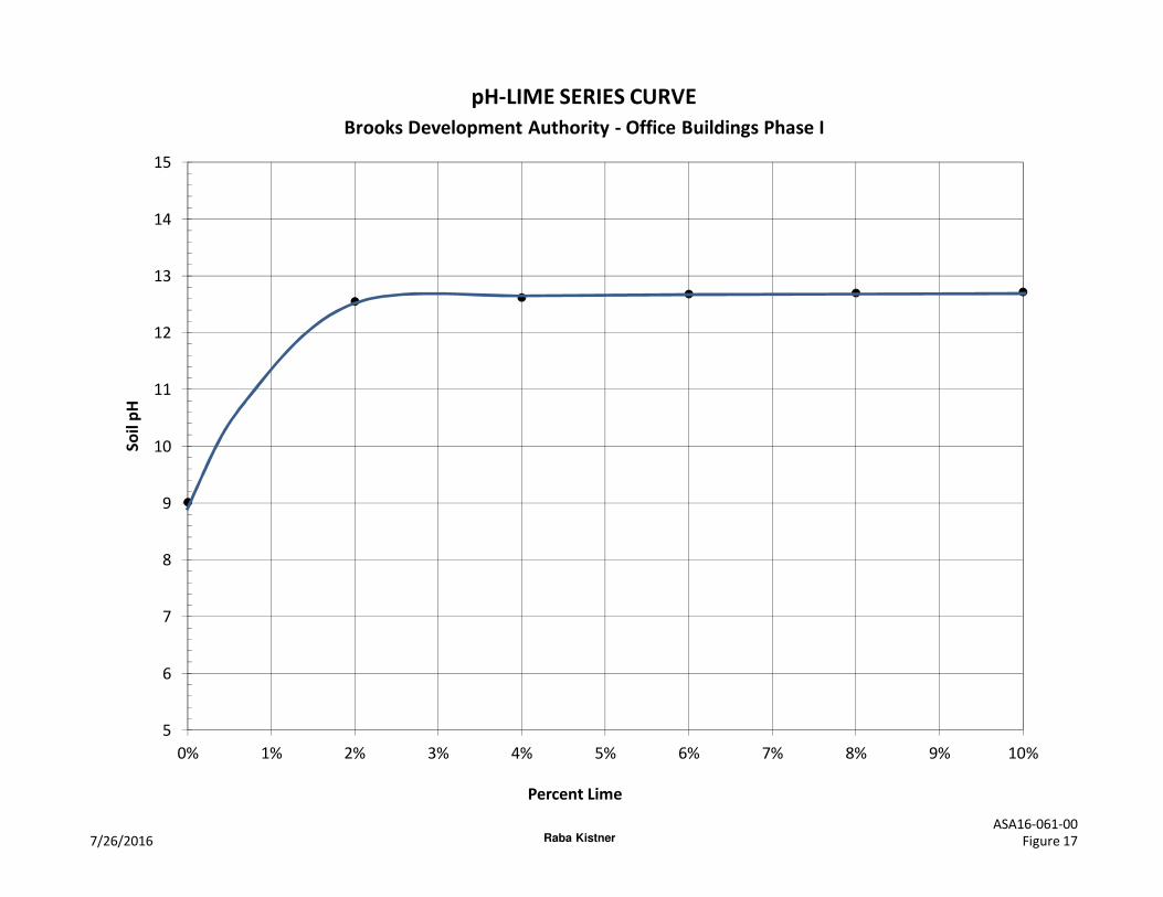
5
6
7
8
9
10
11
12
13
14
15
0% 1% 2% 3% 4% 5% 6% 7% 8% 9% 10%
So
il p
H
Percent Lime
pH-LIME SERIES CURVE
7/26/2016 Figure 17
ASA16-061-00Raba Kistner
Brooks Development Authority - Office Buildings Phase I
Geotechnical-Engineering Report
Geotechnical Services Are Performed for Specific Purposes, Persons, and ProjectsGeotechnical engineers structure their services to meet the specific needs of their clients. A geotechnical-engineering study conducted for a civil engineer may not fulfill the needs of a constructor — a construction contractor — or even another civil engineer. Because each geotechnical- engineering study is unique, each geotechnical-engineering report is unique, prepared solely for the client. No one except you should rely on this geotechnical-engineering report without first conferring with the geotechnical engineer who prepared it. And no one — not even you — should apply this report for any purpose or project except the one originally contemplated.
Read the Full ReportSerious problems have occurred because those relying on a geotechnical-engineering report did not read it all. Do not rely on an executive summary. Do not read selected elements only.
Geotechnical Engineers Base Each Report on a Unique Set of Project-Specific FactorsGeotechnical engineers consider many unique, project-specific factors when establishing the scope of a study. Typical factors include: the client’s goals, objectives, and risk-management preferences; the general nature of the structure involved, its size, and configuration; the location of the structure on the site; and other planned or existing site improvements, such as access roads, parking lots, and underground utilities. Unless the geotechnical engineer who conducted the study specifically indicates otherwise, do not rely on a geotechnical-engineering report that was:• not prepared for you;• not prepared for your project;• not prepared for the specific site explored; or• completed before important project changes were made.
Typical changes that can erode the reliability of an existing geotechnical-engineering report include those that affect: • the function of the proposed structure, as when it’s changed
from a parking garage to an office building, or from a light-industrial plant to a refrigerated warehouse;
• the elevation, configuration, location, orientation, or weight of the proposed structure;
• the composition of the design team; or• project ownership.
As a general rule, always inform your geotechnical engineer of project changes—even minor ones—and request an
assessment of their impact. Geotechnical engineers cannot accept responsibility or liability for problems that occur because their reports do not consider developments of which they were not informed.
Subsurface Conditions Can ChangeA geotechnical-engineering report is based on conditions that existed at the time the geotechnical engineer performed the study. Do not rely on a geotechnical-engineering report whose adequacy may have been affected by: the passage of time; man-made events, such as construction on or adjacent to the site; or natural events, such as floods, droughts, earthquakes, or groundwater fluctuations. Contact the geotechnical engineer before applying this report to determine if it is still reliable. A minor amount of additional testing or analysis could prevent major problems.
Most Geotechnical Findings Are Professional OpinionsSite exploration identifies subsurface conditions only at those points where subsurface tests are conducted or samples are taken. Geotechnical engineers review field and laboratory data and then apply their professional judgment to render an opinion about subsurface conditions throughout the site. Actual subsurface conditions may differ — sometimes significantly — from those indicated in your report. Retaining the geotechnical engineer who developed your report to provide geotechnical-construction observation is the most effective method of managing the risks associated with unanticipated conditions.
A Report’s Recommendations Are Not FinalDo not overrely on the confirmation-dependent recommendations included in your report. Confirmation-dependent recommendations are not final, because geotechnical engineers develop them principally from judgment and opinion. Geotechnical engineers can finalize their recommendations only by observing actual subsurface conditions revealed during construction. The geotechnical engineer who developed your report cannot assume responsibility or liability for the report’s confirmation-dependent recommendations if that engineer does not perform the geotechnical-construction observation required to confirm the recommendations’ applicability.
A Geotechnical-Engineering Report Is Subject to MisinterpretationOther design-team members’ misinterpretation of geotechnical-engineering reports has resulted in costly
Important Information about This
Subsurface problems are a principal cause of construction delays, cost overruns, claims, and disputes.
While you cannot eliminate all such risks, you can manage them. The following information is provided to help.
problems. Confront that risk by having your geo technical engineer confer with appropriate members of the design team after submitting the report. Also retain your geotechnical engineer to review pertinent elements of the design team’s plans and specifications. Constructors can also misinterpret a geotechnical-engineering report. Confront that risk by having your geotechnical engineer participate in prebid and preconstruction conferences, and by providing geotechnical construction observation.
Do Not Redraw the Engineer’s LogsGeotechnical engineers prepare final boring and testing logs based upon their interpretation of field logs and laboratory data. To prevent errors or omissions, the logs included in a geotechnical-engineering report should never be redrawn for inclusion in architectural or other design drawings. Only photographic or electronic reproduction is acceptable, but recognize that separating logs from the report can elevate risk.
Give Constructors a Complete Report and GuidanceSome owners and design professionals mistakenly believe they can make constructors liable for unanticipated subsurface conditions by limiting what they provide for bid preparation. To help prevent costly problems, give constructors the complete geotechnical-engineering report, but preface it with a clearly written letter of transmittal. In that letter, advise constructors that the report was not prepared for purposes of bid development and that the report’s accuracy is limited; encourage them to confer with the geotechnical engineer who prepared the report (a modest fee may be required) and/or to conduct additional study to obtain the specific types of information they need or prefer. A prebid conference can also be valuable. Be sure constructors have sufficient time to perform additional study. Only then might you be in a position to give constructors the best information available to you, while requiring them to at least share some of the financial responsibilities stemming from unanticipated conditions.
Read Responsibility Provisions CloselySome clients, design professionals, and constructors fail to recognize that geotechnical engineering is far less exact than other engineering disciplines. This lack of understanding has created unrealistic expectations that have led to disappointments, claims, and disputes. To help reduce the risk of such outcomes, geotechnical engineers commonly include a variety of explanatory provisions in their reports. Sometimes labeled “limitations,” many of these provisions indicate where geotechnical engineers’ responsibilities begin and end, to help
others recognize their own responsibilities and risks. Read these provisions closely. Ask questions. Your geotechnical engineer should respond fully and frankly.
Environmental Concerns Are Not Covered The equipment, techniques, and personnel used to perform an environmental study differ significantly from those used to perform a geotechnical study. For that reason, a geotechnical-engineering report does not usually relate any environmental findings, conclusions, or recommendations; e.g., about the likelihood of encountering underground storage tanks or regulated contaminants. Unanticipated environmental problems have led to numerous project failures. If you have not yet obtained your own environmental information, ask your geotechnical consultant for risk-management guidance. Do not rely on an environmental report prepared for someone else.
Obtain Professional Assistance To Deal with MoldDiverse strategies can be applied during building design, construction, operation, and maintenance to prevent significant amounts of mold from growing on indoor surfaces. To be effective, all such strategies should be devised for the express purpose of mold prevention, integrated into a comprehensive plan, and executed with diligent oversight by a professional mold-prevention consultant. Because just a small amount of water or moisture can lead to the development of severe mold infestations, many mold- prevention strategies focus on keeping building surfaces dry. While groundwater, water infiltration, and similar issues may have been addressed as part of the geotechnical- engineering study whose findings are conveyed in this report, the geotechnical engineer in charge of this project is not a mold prevention consultant; none of the services performed in connection with the geotechnical engineer’s study were designed or conducted for the purpose of mold prevention. Proper implementation of the recommendations conveyed in this report will not of itself be sufficient to prevent mold from growing in or on the structure involved.
Rely, on Your GBC-Member Geotechnical Engineer for Additional AssistanceMembership in the Geotechnical Business Council of the Geoprofessional Business Association exposes geotechnical engineers to a wide array of risk-confrontation techniques that can be of genuine benefit for everyone involved with a construction project. Confer with you GBC-Member geotechnical engineer for more information.
8811 Colesville Road/Suite G106, Silver Spring, MD 20910Telephone: 301/565-2733 Facsimile: 301/589-2017
e-mail: [email protected] www.geoprofessional.org
Copyright 2015 by Geoprofessional Business Association (GBA). Duplication, reproduction, or copying of this document, or its contents, in whole or in part, by any means whatsoever, is strictly prohibited, except with GBA’s specific written permission. Excerpting, quoting, or otherwise extracting wording from this document
is permitted only with the express written permission of GBA, and only for purposes of scholarly research or book review. Only members of GBA may use this document as a complement to or as an element of a geotechnical-engineering report. Any other firm, individual, or other entity that so uses this document without
being a GBA member could be commiting negligent or intentional (fraudulent) misrepresentation.
ENGINEERING • ENVIRONMENTAL • INFRASTRUCTURE • PROJECT CONTROL
Austin, TX
Brownsville, TX
Dallas, TX
Freeport, TX
San Antonio, TX
Houston, TX
McAllen, TX
New Braunfels, TX
Lake Worth, FL
Lincoln, NE
Salt Lake City, UT
Mexico
RABA KISTNER