AIRFIELD SUBGRADE CONSIDERATIONS WHAT YOU … · AIRFIELD SUBGRADE CONSIDERATIONS WHAT YOU NEED TO...
27
SWIFT 2014 Workshop - Chris Olidis, P.Eng. AIRFIELD SUBGRADE CONSIDERATIONS WHAT YOU NEED TO KNOW
Transcript of AIRFIELD SUBGRADE CONSIDERATIONS WHAT YOU … · AIRFIELD SUBGRADE CONSIDERATIONS WHAT YOU NEED TO...

SWIFT 2014 Workshop - Chris Olidis, P.Eng.
AIRFIELD SUBGRADE
CONSIDERATIONS
WHAT YOU NEED TO KNOW

PRESENTATION OUTLINE
Indentify subgrade design requirements
• Transport Canada pavement design methodology
• Pavement Load Rating (PLR)
How to evaluate
Subgrade construction
Other considerations
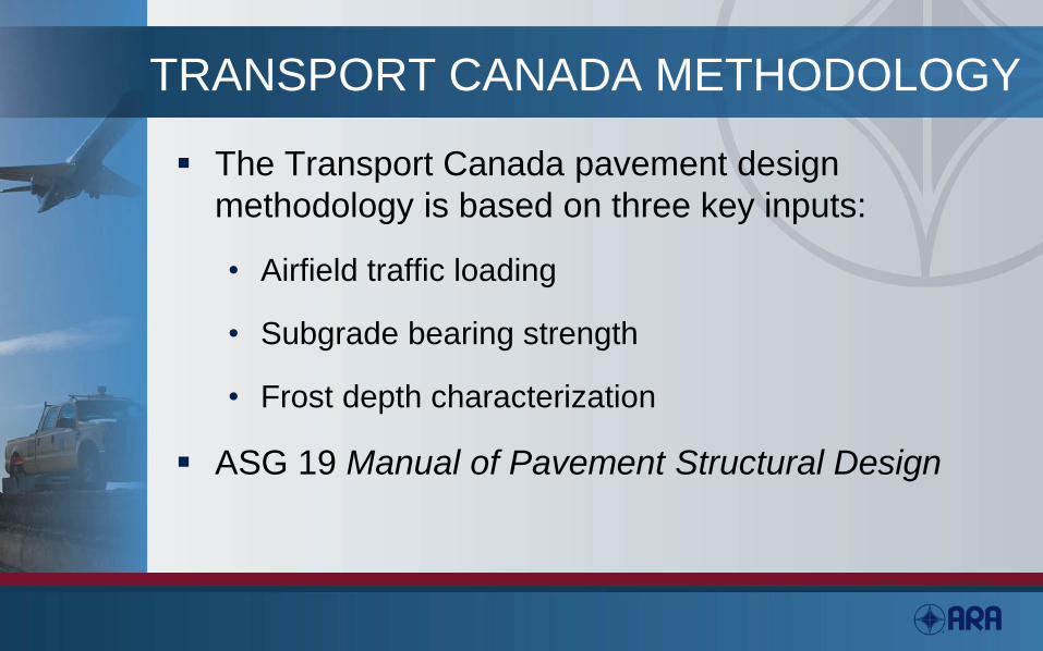
TRANSPORT CANADA METHODOLOGY
The Transport Canada pavement design
methodology is based on three key inputs:
• Airfield traffic loading
• Subgrade bearing strength
• Frost depth characterization
ASG 19 Manual of Pavement Structural Design

SUBGRADE BEARING STRENGTH
Subgrade bearing strength (S)
• Defined as the load (kN) required to produce a
deflection of 12.5 mm after 10 load repetitions
Subject to seasonal fluctuations resulting from
environmental conditions
Lower quartile strength used for design
Extensive database of testing from 1945 to 1995

STATIC REPETITIVE PLATE LOAD TEST
Procedure defined in AK-68-31 Pavement Bearing
Strength Measurement and Analysis
A full day is required to complete testing
Requires
• Load reaction frame
• Steel plate stack (750 mm diameter)
• Reference gauges

PLATE LOAD TEST

PLATE LOAD TEST RELATIONSHIPS
P = S * 10t/165 (flexible pavement)
• P = plate bearing value on pavement surface (kN)
• S = plate bearing value on subgrade surface (kN)
• t = equivalent granular thickness (cm)
k = 0.474 * S * 10t/165 (rigid pavement)
• k = bearing modulus (MPa/m)

TYPICAL ‘S’ VALUES

TYPICAL STRENGTH RELATIONSHIPS

Transport Canada Flexible Pavement
Design Curves

Transport Canada Rigid Pavement
Design Curves
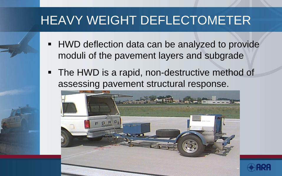
HEAVY WEIGHT DEFLECTOMETER
HWD deflection data can be analyzed to provide
moduli of the pavement layers and subgrade
The HWD is a rapid, non-destructive method of
assessing pavement structural response.

HEAVY WEIGHT DEFLECTOMETER
Evaluated by Transport Canada as an alternative to
plate load testing
Relationships were developed based on maximum
deflection with a 450 mm Φ plate at a 250kN peak
impact load
Heavy Falling Weight Deflectometer vs Static Plate
Load Testing, Report Number AARME/C-02-01

Ps by HWD DEFLECTION

EFFECTS OF FROST
Frost is result of freezing within the pavement
structure
For both rigid and flexible pavements, from 20 to
50 percent of rainfall may infiltrate pavement
structure
Freezing and thawing greatly reduces pavement
support capacity

EFFECTS OF FROST
Frost heaving results from ice lenses
Ice lenses only develop when:
• Frost susceptible materials
• Freezing temperatures penetrate into susceptible
material
• Water supply is available
Eliminate a variable and frost heave is minimized

FROST DESIGN CONCEPTS
Two approaches to frost design • Complete prevention of subgrade freezing
• Limited frost penetration into subgrade
Complete protection generally required when: • Subgrade soil and moisture is extremely variable
• Subgrade has high silt content
• Differential heave will cause operations problems
Conditions for frost design consideration are: • Presence of frost susceptible soil
• Groundwater within 1.5 m of subgrade elevation
• Frost penetration greater than design thickness of pavement

FROST SUSCEPTIBILITY

FREEZING INDICES

TC MINIMUM THICKNESS

ADDITIONAL FROST THOUGHTS
Minimum granular thickness nomograph considers uniform subgrade soils
Provides only partial frost protection
Does not consider pockets of highly frost susceptible soils
• May require sub-excavation to depth of frost
Must consider subsurface drainage

SUBGRADE COMPACTION
As specified in
• ASG-20 Pavement Construction: Methods and Inspection
• ASG-6 Pavement Construction: Materials and Testing
Compaction based on modified Proctor density as determined in the laboratory

SUBGRADE COMPACTION
Layer Material Depth
(mm)
%
Compaction
Pavement
Embankment
Cohesive soil
Non-cohesive soil
90
95
Subgrade Cohesive soil
Non-cohesive soil
Lime modified
150
300
93
98
95

SUBGRADE COMPACTION
FAA AC 150/5320-6
Aircraft
Weight
kips
Non-cohesive, depth in inches Cohesive, depth in inches
100% 95% 90% 85% 95% 90% 85% 80%
Dual
50 12 12-28 28-38 38-50 6 6-10 10-17 17-22
100 17 17-30 30-42 42-55 6 6-12 12-19 19-25
150 19 19-32 32-46 46-60 7 7-14 14-21 21-28
200 21 21-37 37-53 53-69 9 8-16 16-24 24-32
Dual
Tandem
100 14 14-26 26-38 38-49 6 6-10 10-17 17-22
200 17 17-30 30-43 43-56 6 6-12 12-18 18-26
300 20 20-34 34-48 48-63 7 7-14 14-22 22-29
400 23 23-41 41-59 59-76 9 9-18 18-27 27-36
DC-10
L1011
B747
400 21 21-36 36-55 55-70 8 8-15 15-20 20-28
600 23 23-41 41-59 59-76 9 9-18 18-27 27-36
800 23 23-41 41-59 59-76 9 9-18 18-27 27-36

PROOF ROLLING
Specified in ASG-20 Pavement Construction: Methods and Inspection
Used to locate isolated soft spots in compacted soil
Ensure complete coverage across airfield
Proof Roller • Four large rubber tires, 740 mm spacing
• 45,360 kg total mass
• 0.6 MPa tire pressure

PROOF ROLLING EQUIPMENT

QUESTIONS