Base and Subgrade
17
Barry R. Christopher, 1 Scott A. Hayden, 2 and Aigen Zhao 3 Roadway Base and Subgrade Geocomposite Drainage Layers Reference: Christopher, B. R., Hayden, S. A., and Zhao, A., "Roadway Base and Subgrade Geocomposite Drainage Layers," Testing and Performance of Geosynthetics in Subsurface Drainage, ASTM STP 1390, J. B. Goddard, L. D. Suits and J. S. Baldwin, Eds., American Society for Testing and Materials, West Conshohocken, PA, 2000. Abstract: The Maine Department of Transportation (DOT) in conjunction with the University of Maine and the U.S. Army Cold Regions Research Laboratory evaluated the use of a special geocomposite drainage net as a drainage layer and capillary barrier (to mitigate frost heave) on a section of road plagued with weak, frost-susceptible subgrade soils and poor pavement performance. The special geocomposite drainage net that is being used has a higher flow capacity than conventional geonets and, based on tests performed by the University of Illinois, does not deform significantly under heavy traffic loading. For the 425-m-long test section, the geonet drainage geocomposite was placed horizontally across the entire roadway but varied in vertical location to form three separate subsections for evaluating drainage of 1) the base coarse aggregate, 2) the asphaltic concrete pavement, and 3) the subgrade to allow for a capillary break in order to reduce frost action. An integral drainage collection system was installed to collect the water flowing in the geonet. This paper includes a project description, material and construction specifications, installation procedures, instrumentation, and test results based upon two seasons of monitoring. Laboratory characterization and performance testing initially used to evaluate the geocomposite are compared with the monitored results. Keywords: drainage, drain, frost heave, geocomposite, geonet, instrumentation, pavement, roadway Introduction In order to evaluate the potential application of geosynthetics as a roadway drainage layer, the Maine Department of Transportation (DOT) constructed a test section with a 1 Geotechnical Consultant, Christopher Consultants, 210 Boxelder Lane, Roswell, GA 30076. 2 Certified Geologist, Maine Department of Transportation, Geotechnical Section, 219 Hogan Road, Bangor, ME 04401. 3 Technical Director, Tenax Inc., 4800 East Monument Street, Baltimore, MD 21205.
-
Upload
era-era-era -
Category
Documents
-
view
67 -
download
5
description
pavement
Transcript of Base and Subgrade

Barry R. Christopher,1 Scott A. Hayden,2 and Aigen Zhao3 Roadway Base and Subgrade Geocomposite Drainage Layers Reference: Christopher, B. R., Hayden, S. A., and Zhao, A., "Roadway Base and Subgrade Geocomposite Drainage Layers," Testing and Performance of Geosynthetics in Subsurface Drainage, ASTM STP 1390, J. B. Goddard, L. D. Suits and J. S. Baldwin, Eds., American Society for Testing and Materials, West Conshohocken, PA, 2000. Abstract: The Maine Department of Transportation (DOT) in conjunction with the University of Maine and the U.S. Army Cold Regions Research Laboratory evaluated the use of a special geocomposite drainage net as a drainage layer and capillary barrier (to mitigate frost heave) on a section of road plagued with weak, frost-susceptible subgrade soils and poor pavement performance. The special geocomposite drainage net that is being used has a higher flow capacity than conventional geonets and, based on tests performed by the University of Illinois, does not deform significantly under heavy traffic loading. For the 425-m-long test section, the geonet drainage geocomposite was placed horizontally across the entire roadway but varied in vertical location to form three separate subsections for evaluating drainage of 1) the base coarse aggregate, 2) the asphaltic concrete pavement, and 3) the subgrade to allow for a capillary break in order to reduce frost action. An integral drainage collection system was installed to collect the water flowing in the geonet. This paper includes a project description, material and construction specifications, installation procedures, instrumentation, and test results based upon two seasons of monitoring. Laboratory characterization and performance testing initially used to evaluate the geocomposite are compared with the monitored results. Keywords: drainage, drain, frost heave, geocomposite, geonet, instrumentation, pavement, roadway Introduction
In order to evaluate the potential application of geosynthetics as a roadway drainage
layer, the Maine Department of Transportation (DOT) constructed a test section with a 1Geotechnical Consultant, Christopher Consultants, 210 Boxelder Lane, Roswell, GA 30076. 2Certified Geologist, Maine Department of Transportation, Geotechnical Section, 219 Hogan Road, Bangor, ME 04401. 3Technical Director, Tenax Inc., 4800 East Monument Street, Baltimore, MD 21205.

2
special geocomposite drainage net placed horizontally within the pavement section of a road plagued with weak, frost-susceptible subgrade soils and poor pavement performance. Several drainage schemes were evaluated including use of the geocomposite as a roadway aggregate-base drainage layer, a surface pavement drainage layer and a drainage layer to provide a subgrade capillary break to mitigate frost problems. A special geocomposite drainage net was used which had sufficient flow capacity to drain the roadway section and adequate compression stiffness to withstand the anticipated traffic conditions without significant deformation over the life of the pavement. The test section was constructed during the 1997 construction season. This paper provides a project description, material and construction specifications, installation procedures, instrumentation, and test results based upon two seasons of monitoring. Laboratory characterization and performance testing initially used to evaluate the geocomposite are compared to the monitored results.
Drainage in Pavement Systems Water in pavement systems is one of the principal causes of pavement distress. It is
well known that improved roadway drainage extends the life of a roadway system. The Romans found very quickly that drainage was essential for their roads to last (remnants of which still remain!). In the 19th century, MacAdam recognized that it was necessary to have good drainage if adequate support was to be maintained and the road was to last. Adequate drainage is predicted to extend the life of a pavement system up to 2 to 3 times [1,2] over that of undrained pavement sections.
Another drainage issue relates to frost heave and subsequent thaw which causes significant weakening in soils resulting in extensive damage to roadway systems. Frost heave occurs due to the formation of ice lenses in soil which can grow up to several centimeters in thickness and cause expansion of the soil. During thaw, either a void or very soft wet soil replaces the ice lenses resulting in a very weak support condition. Conditions necessary for frost heave include: freezing temperatures, the presence of frost-susceptible soil and availability of water to the freezing front. If water is available, it can migrate through capillary action towards the freezing front and form ice lenses even where the water table is a meter or more below the depth of frost penetration [3]. In Maine and many other cold regions traffic weight restrictions must be posted during the spring thaw.
Conventional Solutions Incorporating free draining base aggregate into the design provides a good solution
to the drainage problem and is the current trend in long life roadway design as documented by NCHRP synthesis 239 [4]. However, free draining aggregate typically requires an asphaltic or cement stabilization binder to facilitate construction and either a

3
graded granular or geotextile filter to prevent migration of subgrade fines into the open graded base, adding significantly to the cost of the roadway. The geotechnical solution to the frost heave problem usually is to remove the frost susceptible soils down to frost depth and replace the soil with non-frost susceptible material. This may require excavation and replacement of over a meter or more of material. Because of the expense of over excavation and the non-frost susceptible select granular material, this solution is often not performed to the extent necessary. Because of the increasing cost of clean granular material, often the backfill contains significant fines and is still somewhat frost susceptible. Another solution to this problem is to use deep drainage trenches to lower the water table and provide transition zones to limit over excavation; however, it is often difficult to lower the water table to a satisfactory depth.
A layer of granular soil has also been placed above the water table as a capillary break and backfilled with frost-susceptible soils to minimize frost heave and related damage in pavements [5]. This concept used geotextile filters above and below the granular layer to prevent intrusion of the adjacent soils. However, high construction costs have deterred the use of this alternative. Thick nonwoven geotextiles have also been evaluated for their potential to provide a capillary break [3,6]. Although the use of a nonwoven geotextile seemed promising, recent work by Henry [7] suggest that they are unlikely to act as a capillary barrier for long term field conditions.
Potential Geocomposite Drainage Layer Solutions A potential alternative for both improved drainage and reduction in frost heave
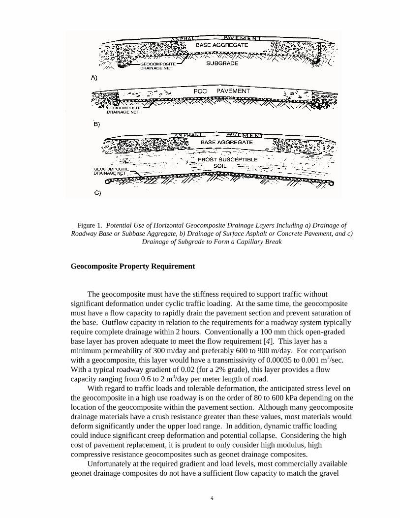
would be to incorporate a low compression, geocomposite drainage layer tied into roadway edge drains as shown in Figure 1. The geocomposite drain could be placed between the base and the subgrade, dramatically shortening the drainage path for the base (i.e., to just the thickness of the base versus the width of the road) thus allowing for less select base materials with a higher fines content as shown in Figure 1a). As the pavement ages and cracks are formed, a majority of the water will enter through the pavement surface. Thus it may be more advantageous to locate a drainage layer directly beneath the pavement surface to collect any infiltration before it enters the base and provide more rapid removal as shown in Figure 1b.
For deep frost penetration, the geocomposite net could be placed at a lower depth as a capillary break, replacing the granular layer shown in Figure 1c. Frost-susceptible backfill could then be placed directly over the geocomposite to the pavement base grade level. In this case, the system could be tied into drainage outlets to maintain the groundwater table at or below that depth. This may potentially eliminate the development of ice lenses which in turn could result in the removal of posting traffic weight restrictions during the spring thaw in cold regions.
4
Figure 1. Potential Use of Horizontal Geocomposite Drainage Layers Including a) Drainage of Roadway Base or Subbase Aggregate, b) Drainage of Surface Asphalt or Concrete Pavement, and c)
Drainage of Subgrade to Form a Capillary Break
Geocomposite Property Requirement The geocomposite must have the stiffness required to support traffic without
significant deformation under cyclic traffic loading. At the same time, the geocomposite must have a flow capacity to rapidly drain the pavement section and prevent saturation of the base. Outflow capacity in relation to the requirements for a roadway system typically require complete drainage within 2 hours. Conventionally a 100 mm thick open-graded base layer has proven adequate to meet the flow requirement [4]. This layer has a minimum permeability of 300 m/day and preferably 600 to 900 m/day. For comparison with a geocomposite, this layer would have a transmissivity of 0.00035 to 0.001 m2/sec. With a typical roadway gradient of 0.02 (for a 2% grade), this layer provides a flow capacity ranging from 0.6 to 2 m3/day per meter length of road.
With regard to traffic loads and tolerable deformation, the anticipated stress level on the geocomposite in a high use roadway is on the order of 80 to 600 kPa depending on the location of the geocomposite within the pavement section. Although many geocomposite drainage materials have a crush resistance greater than these values, most materials would deform significantly under the upper load range. In addition, dynamic traffic loading could induce significant creep deformation and potential collapse. Considering the high cost of pavement replacement, it is prudent to only consider high modulus, high compressive resistance geocomposites such as geonet drainage composites.
Unfortunately at the required gradient and load levels, most commercially available geonet drainage composites do not have a sufficient flow capacity to match the gravel

5
layer drainage level. Typical in-soil transmissivity values of geonet with two 270 g/m2 needle-punched nonwoven geotextiles laminated to both sides is on the order 1 x 10⁻⁴ m2/sec to 5 x 10⁻⁴ m2/sec [8,9] or even lower [10]. Further reduction in these transmissivity values due to long-term compressive creep of the geonet must also be taken into account. This may be why geonet drainage composites have not reportedly been used in this application. Although lower flow rates may be acceptable for some projects, considering this was a first trial, an equivalent flow rate to the gravel layer was desired. In addition, to provide a capillary break, it is critical that an air void exist within the geocomposite [7]. Geotextile intrusion on typical, relatively thin geonets is often sufficient to allow the geotextile filters on opposite sides of the geonet to touch, thus eliminating the air void. This was especially a concern for the lower drainage layer, which would be placed between soft clayey soils and have an increased geotextile intrusion potential. On the basis of these two considerations a thicker, higher flow capacity geonet drainage composite than typically available was desirable.
At the time of the project, a high flow geonet drainage composite (Tendrain 100-2 by the Tenax Corporation) had recently been introduced that met the flow requirements and did not allow the geotextile layers to touch. This new geocomposite consists of three extruded net layers to form a tri-planar geonet inner core with a needlepunched nonwoven geotextile laminated to either side. The composite has a transmissivity of 0.0022 m2/sec under a normal load of 720 kPa and a gradient of 0.1, with corresponding flow capacity of 19 m3/day/m at a gradient of 0.1 and 3.8 m3/day/m at a gradient of 0.02, based on ASTM Test Method for Constant Head Hydraulic Transmissivity (In-Plane Flow) of Geotextiles and Geotextile Related Products (D 4716). Typical transmissivity data indicate that the transmissivity of a geonet decreases with increasing gradients. Consequently, the use of a laboratory-transmissivity value at a gradient higher than the actual field value (i.e., 0.1 gradient for 2% grade) will be conservative for evaluating flow capacity. The hydraulic characteristic thus corresponds very well with the horizontal drainage layer requirements for roadway drainable base. In addition, long term compressive creep tests on the tri-planar geonet core indicated that the material retained over 60% thickness after 10,000 hours under sustained normal load of 1200 kPa.
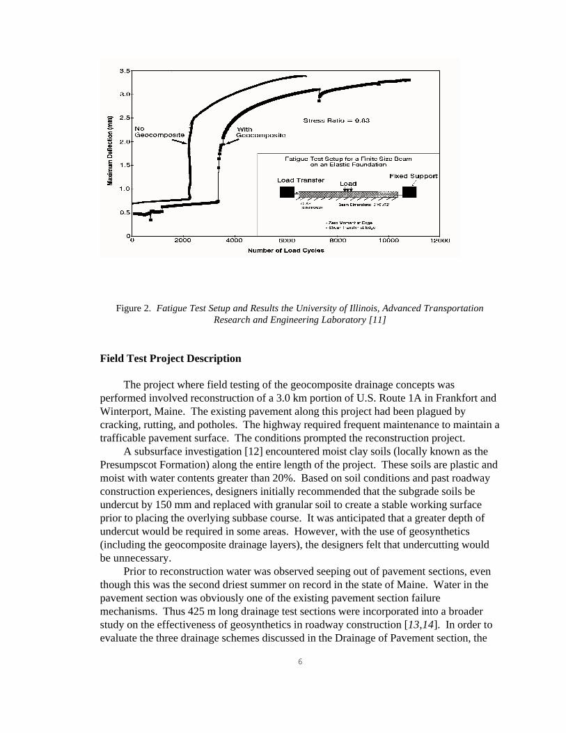
To further evaluate the performance of this geocomposite in a roadway system, cyclic loading tests were performed at the University of Illinois, Advanced Transportation Research and Engineering Laboratory [11]. Cyclic fatigue testing was performed on a concrete beam supported by the geocomposite overlying a clay subgrade and compared to results from a beam supported by the subgrade alone. The tests were performed at stress ratios of 0.76 and 0.83. The test setup along with representative results are shown in Figure 2. The results found insignificant additional deformation in the concrete when the geocomposite was used. The test at the 0.83 stress ratio showed some improvement in fatigue life (visually cracked beam) and the test at 0.76 stress ratio showed some reduction in fatigue life. Although the test results were inconclusive in relation to fatigue life, the geocomposite improved post-cracking behavior of the beam at both stress levels (i.e., minimized continued widening of the crack after break). This improvement in beam performance was attributed to an improvement in the uniformity of support under the beam after cracking and/or frictional improvement at the bottom of the beam which reduced the post-cracking deflection.
6
Figure 2. Fatigue Test Setup and Results the University of Illinois, Advanced Transportation Research and Engineering Laboratory [11]
Field Test Project Description The project where field testing of the geocomposite drainage concepts was
performed involved reconstruction of a 3.0 km portion of U.S. Route 1A in Frankfort and Winterport, Maine. The existing pavement along this project had been plagued by cracking, rutting, and potholes. The highway required frequent maintenance to maintain a trafficable pavement surface. The conditions prompted the reconstruction project.
A subsurface investigation [12] encountered moist clay soils (locally known as the Presumpscot Formation) along the entire length of the project. These soils are plastic and moist with water contents greater than 20%. Based on soil conditions and past roadway construction experiences, designers initially recommended that the subgrade soils be undercut by 150 mm and replaced with granular soil to create a stable working surface prior to placing the overlying subbase course. It was anticipated that a greater depth of undercut would be required in some areas. However, with the use of geosynthetics (including the geocomposite drainage layers), the designers felt that undercutting would be unnecessary.
Prior to reconstruction water was observed seeping out of pavement sections, even though this was the second driest summer on record in the state of Maine. Water in the pavement section was obviously one of the existing pavement section failure mechanisms. Thus 425 m long drainage test sections were incorporated into a broader study on the effectiveness of geosynthetics in roadway construction [13,14]. In order to evaluate the three drainage schemes discussed in the Drainage of Pavement section, the
7
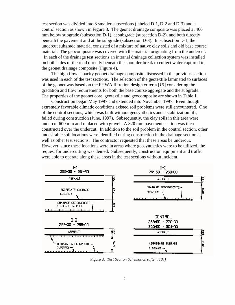
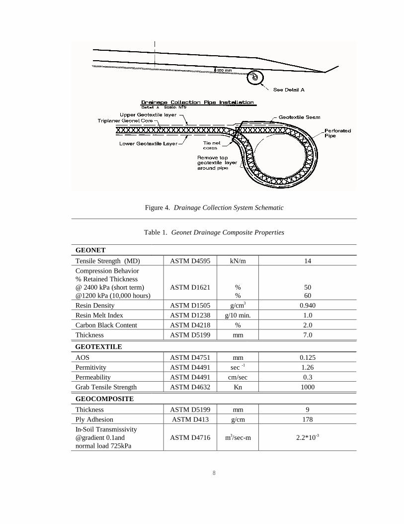
test section was divided into 3 smaller subsections (labeled D-1, D-2 and D-3) and a control section as shown in Figure 3. The geonet drainage composite was placed at 460 mm below subgrade (subsection D-1), at subgrade (subsection D-2), and both directly beneath the pavement and at the subgrade (subsection D-3). In subsection D-1, the undercut subgrade material consisted of a mixture of native clay soils and old base course material. The geocomposite was covered with the material originating from the undercut. In each of the drainage test sections an internal drainage collection system was installed on both sides of the road directly beneath the shoulder break to collect water captured in the geonet drainage composite (Figure 4).
The high flow capacity geonet drainage composite discussed in the previous section was used in each of the test sections. The selection of the geotextile laminated to surfaces of the geonet was based on the FHWA filtration design criteria [15] considering the gradation and flow requirements for both the base course aggregate and the subgrade. The properties of the geonet core, geotextile and geocomposite are shown in Table 1.
Construction began May 1997 and extended into November 1997. Even though extremely favorable climatic conditions existed soil problems were still encountered. One of the control sections, which was built without geosynthetics and a stabilization lift, failed during construction (June, 1997). Subsequently, the clay soils in this area were undercut 600 mm and replaced with gravel. A 820 mm pavement section was then constructed over the undercut. In addition to the soil problem in the control section, other undesirable soil locations were identified during construction in the drainage section as well as other test sections. The contractor requested that these areas be undercut. However, since these locations were in areas where geosynthetics were to be utilized, the request for undercutting was denied. Subsequently, construction equipment and traffic were able to operate along these areas in the test sections without incident.
Figure 3. Test Section Schematics (after [13])
8
Figure 4. Drainage Collection System Schematic
Table 1. Geonet Drainage Composite Properties
GEONET
Tensile Strength (MD)
ASTM D4595
kN/m
14
Compression Behavior % Retained Thickness @ 2400 kPa (short term) @1200 kPa (10,000 hours)
ASTM D1621
% %
50 60
Resin Density ASTM D1505
g/cm3
0.940
Resin Melt Index ASTM D1238
g/10 min.
1.0
Carbon Black Content ASTM D4218
%
2.0
Thickness ASTM D5199
mm
7.0
GEOTEXTILE
AOS
ASTM D4751
mm
0.125
Permitivity ASTM D4491
sec -1
1.26
Permeability ASTM D4491
cm/sec
0.3
Grab Tensile Strength ASTM D4632
Kn
1000
GEOCOMPOSITE
Thickness
ASTM D5199
mm
9
Ply Adhesion
ASTM D413
g/cm
178 In-Soil Transmissivity @gradient 0.1and normal load 725kPa
ASTM D4716
m3/sec-m
2.2*10-3

9
Drainage Instrumentation Water is allowed to drain from the drainage collection system at eight separate
locations labeled outlet A through H. Monitoring stations were constructed at six outlet locations A through F (Table 2). At each of the monitored locations the outlet pipe is connected to a tilt bucket (Figure 5) housed in a protective wooden structure. A micro switch is positioned on the tilt buckets and is actuated every other time the tilt bucket dumps. The micro switch is, in turn, connected to a traffic counter which records the number of dump cycles of each tilt bucket. Data is collected continually 24 hours a day. The traffic counter software then provides daily or monthly reports, which presents the total number of dump cycles per hour, per day. This information is then downloaded over phone lines from the traffic counter on project to the Maine Department of Transportation offices.
Stand pipe type well points were installed outside the roadway at three locations along the drainage test section to provide ground water level information. These were read manually with a tape. Although the well points could not provide water level values directly under the roadway, they were useful in identifying the general relationship between ground water and roadway drainage.
Table 2. Monitored Outlet Locations and Details
Monitored
Outlet Locations
Test Section
Drainage Pipe Location
Geocomposite Location
Outlet A 261+40 right
D-1 255+0 – 260+00 right 152 m drained section
Geocomposite is located (460 mm) below subgrade and is placed along the low side of a super elevated turn.
Outlet B 261+40 left
D-1
260+00 - 261+50 left 46 m drained section
Geocomposite located (460 mm) below subgrade in a standard section.
Outlet C 261+40 right
D-1
260+00 - 261+50 right 46 m drained section
Geocomposite located (460 mm) below subgrade in a standard section.
Outlet D 268+00 left
D-2
261+50 - 268+00 left 200 m drained section
Geocomposite is located at subgrade along the low side of a super elevated turn in areas.
Outlet E 268+00 left
D-3
268+00 - 269+00 30 m drained section
Geocomposite is located at subgrade in a standard section.
Outlet F 268+00 left
D-3
268+00 - 269+00 30 m drained section
Geocomposite is located directly beneath the pavement in a standard section.

10
Figure 5. Tilt Bucket Schematic [13, revised from Wisconsin DOT]
Rainfall at the site and temperature were obtained from a weather station in the vicinity of the project. Thermocouples were also installed within the drainage sections to monitor frost penetration. In order to evaluate the potential influence of the geocomposite on dissipation of pore pressure in the base course aggregate and the subgrade, vibrating wire piezometers (Roctest model PWS) were placed in the subgrade approximately 150 mm below the geocomposite and at two levels above the geocomposite in each drainage subsection and at three corresponding locations in the control section and in a test section where a geotextile was used as a separation layer between the base and subgrade. For more details see reference Hayden et al. [13]. The instrumentation was also complemented with a periodic survey of the pavement surface and falling weight deflectometer (FWD) tests. The pavement surface surveys were conducted between the months of December and April to measure frost heave. FWD tests were performed prior to reconstruction and in April 1998 soon after the end of the spring thaw. The pavement thickness varied in the test section from 127 to 254 mm prior to construction. The pavement was 146 mm thick after construction. Drainage Geocomposite Test Section Results Drainage Discharge Results Data collection began in March 1998 for outlets B through F. Data collection at outlet A did not begin until late June. Discharge volumes in liter per meter of section length (l/m) from monitored outlets per length drained section are listed in Table 3 and plotted in Figure 6 along with monthly rainfall.

11
Table 3. Discharge Volumes from Monitored Outlets Per Length of Drained Section
Monitoring Period
Discharge Volumes Per Length of Drained Section (L/m)
Outlet Outlet Outlet Outlet Outlet Outlet Monthly Totals A B C D E F D-1 D-1 D-1 D-2 D-3 D-3 Mar-98 - 77 1094 118 0 0 1289 Apr-98 - 0 0 91 0 0 91 May-98 - 0 0 94 0 0 94 Jun-98 0 4 63 73 6 0 146 Jul-98 2 0 339 56 0 0 397 Aug-98 0 0 7 0 0 0 7 Sep-98 0 0 80 0 0 0 80 Oct-98 0 0 22 79 17 0 118 Nov-98 0 0 51 102 0 0 153 Dec-98 0 0 18 21 0 0 39 Jan-99 0 0 0 0 0 0 0 Feb-99 0 0 1 0 0 0 1 Mar-99 0 16 843 464 41 0 1364 Totals 2 97 2518 1098 64 0 3,779
Figure 5. Monthly Discharge Volumes (per Length of Drained Section) and Rainfall

12
The volume (l/m) totals for each outlet indicates that outlet C recorded the highest volume per length drained section and outlet F recorded the least flow. The greatest monthly flow recorded at each of the monitored locations for 1998 was encountered during the month of March. Discharge volumes per length drained were considerably less for the other months. The volume (l/m) of discharge in the month of March accounted for 53% of the total one year discharge volume. Discharge during the months of April through August accounted for less than 10% of the total for the 1998 monitoring season except for the month of July which accounted for 20% of the total. This trend appears to be continuing in 1999 with March again showing a significant magnitude of flow. Heavy flow activity during the month of March corresponds strongly with the thawing of ice lenses as verified by thermocouple readings and frost heave elevation surveys. The flow observations tend to confirm the results of drainage studies in cold regions performed by Hagen and Cochran [16] (1996). They also found that the highest flows out of pavement, higher than any rain event throughout the year, occurred during the spring thaw. Outlet C recorded the greatest discharge of the six monitored outlets. Water discharged (l/m) from Outlet C is collected from a 45 m run of drainage geocomposite located 460 mm below subgrade in the thawing region. Outlet D recorded the second greatest discharge (l/m) during March. This outlet drains a 200 m length of road with the drainage geocomposite placed directly at subgrade. Discharge during the first year of monitoring ( March 1998 _ March 1999 ) corresponds strongly with precipitation events and water table levels. Over 800 mm of rain fell on the project area during the monitoring year period. Tilt bucket activity would begin shortly after each rain event and ended the same day or the next day after the rain ceased. As the water table lowered through summer, the time between rainfall and tilt bucket activity increased. Based on the AASHTO [17] definitions for pavement drainage capacity, the quality of drainage in the geocomposite test section would be good (i.e., water removed within one day) to excellent (water removed within 1 day). Outlet C and Outlet D recorded the greatest discharge (l/m) of the monitoring period with 67% and 30% respectively for the 1998 monitoring season respectively. Again, water discharged from Outlet C is collected from a drainage geocomposite located below subgrade and water discharged from Outlet D is collected from a drainage geocomposite located directly at subgrade. Outlets E and F recorded very little water discharge. Outlet E only recorded a total discharge volume of 64 liters per meter of section drained. Outlet F recorded even less with only a trace of water. Outlets E and F drain a 30 m length section constructed on a fill area. Outlet E collects water from the geocomposite placed at subgrade whereas Outlet F collects water from the geocomposite placed directly beneath the asphalt pavement. Based upon tilt bucket limitations, the volumes recorded at each of the six monitored outlet locations could be considerably lower than the actual volumes. The tilt buckets were not able to dump when subjected to flow rates greater than approximately 7 l/min. Flow rates as high as 57 l/min were measured manually during site visits. At that rate, the geonet drainage composite is near its flow capacity. In addition, tilt buckets experienced difficulties in accurately measuring flow rates less than 0.25 l/min due to surface tension. Site visits revealed that water being discharged at these low flow rates failed to drop vertically into the collection bin but rather clung to the sides and traveled down the inner walls and exited the tilt bucket without ever entering the collection bin.
13
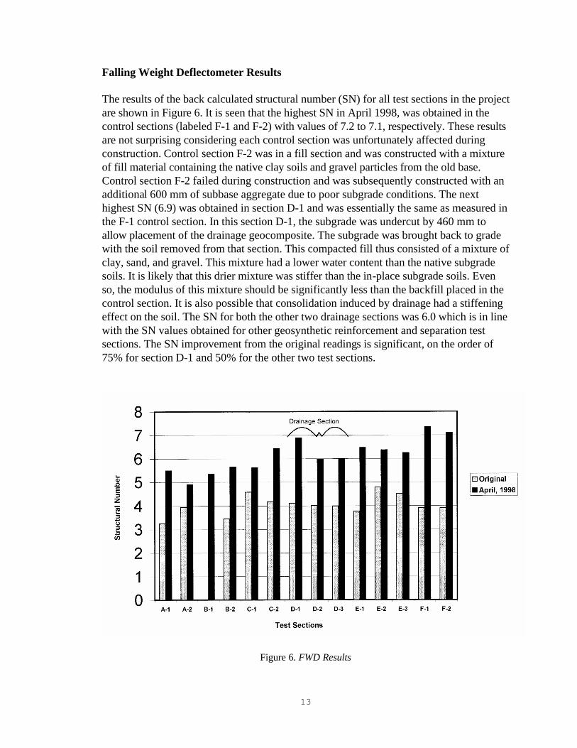
Falling Weight Deflectometer Results The results of the back calculated structural number (SN) for all test sections in the project are shown in Figure 6. It is seen that the highest SN in April 1998, was obtained in the control sections (labeled F-1 and F-2) with values of 7.2 to 7.1, respectively. These results are not surprising considering each control section was unfortunately affected during construction. Control section F-2 was in a fill section and was constructed with a mixture of fill material containing the native clay soils and gravel particles from the old base. Control section F-2 failed during construction and was subsequently constructed with an additional 600 mm of subbase aggregate due to poor subgrade conditions. The next highest SN (6.9) was obtained in section D-1 and was essentially the same as measured in the F-1 control section. In this section D-1, the subgrade was undercut by 460 mm to allow placement of the drainage geocomposite. The subgrade was brought back to grade with the soil removed from that section. This compacted fill thus consisted of a mixture of clay, sand, and gravel. This mixture had a lower water content than the native subgrade soils. It is likely that this drier mixture was stiffer than the in-place subgrade soils. Even so, the modulus of this mixture should be significantly less than the backfill placed in the control section. It is also possible that consolidation induced by drainage had a stiffening effect on the soil. The SN for both the other two drainage sections was 6.0 which is in line with the SN values obtained for other geosynthetic reinforcement and separation test sections. The SN improvement from the original readings is significant, on the order of 75% for section D-1 and 50% for the other two test sections.
Figure 6. FWD Results

14
It should also be noted that some sections of the original road had up to 619 mm of asphalt. Additional FWD readings are being conducted within the drainage test sections during the spring thaw to investigate and compare the reflection curves to determine if there is a noticeable difference between these curves represented by the soils ability to regain it _s strength as water is removed from the soil. Data are not available at this time. It should also be noted that some sections of the original road had up to 619 mm of asphalt. Additional FWD readings are being conducted within the drainage test sections Piezometer Results Unfortunately difficulties were encountered in reading the piezometers during the critical spring thaw due to both equipment and winter environment problems. Average readings during the fall of 1997 and the summer of 1998 can, however, be compared as shown in Table 4 [18]. These readings show that during the fall of 1997, the drainage sections D-2 and D-3 had lower pressure readings than the control section in both the base and the subgrade suggesting the geocomposite placed at the subgrade interface removed water from the pavement system. Section D-1 had a lower pressure in the base aggregate and the subgrade below the geocomposite but was higher in the clayey backfill over the geocomposite when compared to the control section. This is not surprising considering the subgrade in the control section was placed as compacted fill. Although the summer of 1998 readings indicate a significantly lower pore pressure in the geocomposite drainage section than the control section, the negative pore pressures which would normally indicate partially saturated conditions may also be the result of damaged transducers caused by freezing in the winter.
Table 4. Average Values of Piezometers [18]
Average piezometric values for dates 10/22/97 to 11/25/97 Piezometric Head (mm) Section Top Middle Bottom Separation Geotextile at 820 mm C-2 138 95 210 Geocomposite 460 mm below subgrade D-1 29 359 3 Geocomposite at 820 mm D-2 10 52 -15 Geocomposite at 180 and 820 mm D-3 118 23 74 Control - No Geosynthetic Control 414 348 149 Average piezometric values for dates 6/27/98 to 8/19/98 Separation Geotextile at 820 mm C-2 -138 -154 -224 Geocomposite 460 mm below subgrade D-1 -82 -88 58 Geocomposite at 820 mm D-2 -501 -110 -84 Geocomposite at 180 and 820 mm D-3 -158 -154 -151 Control - No Geosynthetic Control 237 247 378

15
Frost Heave Minimal frost heave has been observed thus far in any of the test sections and it may take several additional seasons to provide discernible results. Freezing tests on the subgrade soil with and without the geocomposite as a capillary barrier were also conducted [19]. Analyses of frost heave will be reviewed and presented in a separate paper as soon as significant results have been obtained. Conclusions Data from drainage monitoring outlets indicate that a high flow capacity geonet drainage composite placed at subgrade or below subgrade is successful in rapidly removing water from beneath the roadway. The placement of such a drainage layer proved especially useful for removing the most damaging waters present during the spring thaw. More water was removed from the roadway section during the spring thaw than during the highest rainfall period throughout the year. A measured improvement in stiffness for the section in which the drain was placed in the subgrade may have been the result of this drainage as well as greater compaction of the soil placed over the geocomposite. Drainage during summer months was best realized where the geonet drainage composite was placed within cut sections in areas where the water table was relatively shallow. The drainage quality provided by the geonet drainage composite would be classified as good to excellent based on AASHTO [17] requirements. In addition to providing improved drainage, the geonet drainage composite facilitated construction in areas where the subgrade was weak without requiring additional undercuts. In the control area where geosynthetics were not used an additional 600 mm of stabilization aggregate was required. The magnitude of water discharging from the drainage section is significant and should significantly improve the long-term performance of the road in comparison to undrained sections. Drainage and associated rapid improvement in pavement support in the spring may also allow for a reduction or earlier removal of load restrictions, resulting in significant transport savings. Unfortunately we may not see this influence for a number of years. It is hoped that designers will take note and not wait that long to implement this technology. Acknowledgments This project involved the expertise from many other people besides the authors. In great appreciation we would like to thank and recognize the following individuals for their technical support: Dr. Dana Humphrey and Ms. Christine Fetten from the University of Maine; Mr. Phil Dunn, Mr. Steve Hall, Mr. Steve Colson, Mr. Terry White and Mr. Victor Smith of MDOT; and Ms. Karen Henry and Ms. Rosa Affleck of CRREL. We would also like to thank the Maine DOT and the Tenax Corporation for their vision and financial support that enabled us to pursue this work.

16
References [1] Cedergren, H.R., 1987, Drainage of Highway and Airfield Pavements, Robert E. Lrieger Publishing Co. Inc., Malabar, FL. [2] Forsyth, R.A., G.K. Wells, and J.H. Woodstrom, 1987, "The Economic Impact of Pavement Subsurface Drainage," Transportation Research Record No. 1121, Transportation Research Board, Washington, D.C. [3] Henry, K.S., (1991), "Effect of Geotextiles on Water Migration in Freezing Soils and The Influence of Freezing on Performance," Proceedings of Geosynthetics '91, Atlanta, Georgia, pp. 469-483. [4] Christopher, B.R. and McGuffey, V.C., 1997, Pavement Subsurface Drainage Systems, National Cooperative Highway Research Program, Synthesis of Highway Practice 239, Transportation Research Board, National Academy Press, Washington, D.C., 44 p. [5] Rankilor, P.R., Membranes in Ground Engineering, John Wiley & Sons, Inc., London, England, 1981. [6] Henry, K.S. and Christopher, B.R., "Pavement Test Section to Determine the Effect of Geotextile on Frost Heave," Proceedings of Geosynthetics '93, Vol. 1, Vancouver, BC, Canada, 1993, pp. 95-109. [7] Henry, K.S, "The Use of Geosynthetics to Mitigate Frost Heave in Soils," Ph. D. Dissertation, Civil Engineering Department, University of Washington, Seattle, WA., 1998, 333p. [8] Gardoni, M. G. A. and Palmeira, E. M., "Transmissivity of Geosynthetics Under High Normal Stresses," Proceedings of Geosynthetics '99, Vol. 2, Boston, Massachusetts, 1999, pp. 769-782. [9] Koerner, R. M., Designing with Geosynthetics, Fourth Edition, Prentice Hall, Englewood Cliffs, New Jersey, 1997.. [10] Zao, A. and Montanelli, F., "Effect of Soil Presence on Flow Capacity of Drainage Geocomposites Under High Normal Loads," Proceedings of Geosynthetics '99, Vol. 2, Boston, Massachusetts, 1999, pp. 799-812. [11] Dempsey, "Fatigue Performance of a Fully Supported Concrete Beam with a Geocomposite Layer," unpublished report prepared for Barry R. Christopher, 1996, 6 p.

17
[12] Hayden, S.A., ÿÿA Subsurface Investigation for a 1.9 Mile Portion of Route 1A in the Towns of Frankfort and Winterport,ÿÿ unpublished report, State of Maine Department of Transportation, Report No. 96-11, Bangor, ME., 1996, 40 p. [13] Hayden, S.A., Christopher, B.R., Humphrey, D.N., Fetten, C.P., and Dunn, P.A., Jr., ÿÿInstrumentation of Reinforcement, Separation and Drainage Geosynthetic Test Sections used in the reconstruction of a Highway in Maine,ÿÿ Proc., 9th International Conference on Cold Regions Engineering, Duluth, MN., 1998, pp. 420-433. [14] Hayden, S.A., Humphrey, D.N., Christopher, B.R., Henry, K.S., and Fetten, C.P., "Effectiveness of Geosynthetics for Roadway Construction in Cold Regions: Results of a Multi-Use Test Section," Proceedings of Geosynthetics '99, Vol. 2, Boston, Massachusetts, 1999, pp.847-862. [15] Holtz, R.D., Christopher, B.R., and Berg, R.R., Geosynthetic Design and Construction Guidelines (Participant Notebook), NHI Course No. 13213, FHWA Publication No. HI-95-038, Federal Highway Administration, Washington, D.C., 1998, 396 p. [16] Hagen, M.G., and G.R. Cochran, "Comparison of Pavement Drainage Systems," Transportation Research Paper #960203, Transportation Research Board, Washington, D.C., 1996. [17] AASHTO, AASHTO Guide for Design of Pavement Structures, American Association of State Highway and Transportation Officials, Washington, D.C., 1993. [18] Fetten and Humphrey, "Instrumentation and Performance of Geosynthetics Beneath Flexible Pavements in Winterport and Frankfort, Maine," Report prepared for the Maine Department of Transportation, Bureau of Planning, Research, & Community Services, Transportation Research Division, Technical Report 97-14, 1998, 137 p. [19] Henry, K.S., and Afflect, R., "Freezing Tests on Lean Clay with Tenax Tri-Planar Geocomposite as Capillary Barrier," Contract Report to Tenax, Inc., from U.S. Army Cold Regions Research and Engineering Laboratory, Hanover, NH., 1998, 13 p.