GeoPak Road 2 - MoDOT Design...
25
4/8/17 Missouri Department of Transportation GeoPak Road 2 Advance Terrain Modeling
Transcript of GeoPak Road 2 - MoDOT Design...

4/8/17 Missouri Department of Transportation
GeoPak Road 2 Advance Terrain Modeling


GEOPAK Road 2 Advanced Terrain Modeling
4/8/17 Missouri Department of Transportation 1
19.1 Terrain Model Create
The Terrain Model Create tool group contains tools to create a terrain model from graphical
elements, ASCII files, point clouds, LandXML, and importing from various Bentley Civil
products. Tools are also supported to merge together two or more models, and to clip models.
Select in the
Toolbox
Description
Create from File
Creates a terrain model by importing from an external file. Numerous file
formats are supported supported such as USGS DEM, DTED, Lidar (*.las),
and native products (InRoads, GEOPAK, and MX).
Create Terrain
Model by
Graphical Filter
An automated way of storing search settings for graphic elements to
automate Create Terrain Model by Elements. Uses the settings stored by
Graphical Filter Manager to create the terrain.
Create from
Elements
Creates a terrain model from 3D graphical elements.
Create Complex
Terrain Model
Creates a new Complex terrain model by merging/appending multiple
terrain models.
Create Clipped
Terrain Model
Creates a terrain model by clipping an existing terrain model and providing
an optional horizontal or vertical offset.
Create Corridor
Alternate Surface
Creates a terrain model from user-specified points in a corridor model along
any given path.

Advanced Terrain Modeling GEOPAK Road 2
2 Missouri Department of Transportation 4/8/17
Select in the Toolbox Description
Create Terrain Model from
ASCII File
Creates a terrain model by importing from an ASCII file type using
a user customizable format files.
Create from Point Cloud
Creates a terrain model from MicroStation Point Cloud data.
Create Delta Terrain
Model
Creates a new terrain model by the difference between 2 terrain
models or a terrain model and a plane (elevation).
Create Terrain by Text
Interpolation
Creates a terrain model from 2D graphics which also contain an
elevation label.

GEOPAK Road 2 Advanced Terrain Modeling
4/8/17 Missouri Department of Transportation 3
19.1.1 Edit Terrain Model
These editing commands are for a terrain model that has no graphic elements with rules. For
example, importing terrain models from other formats without creating features. The commands
allow limited editing without returning to the source and importing features. If you need
additional editing capabilities then import the original source and use the other editing methods.
Settings Description
Delete Vertex deletes the specified vertex, then re-triangulates the terrain model without it.
Note you cannot select a vertex that is on the edge of the terrain model
(boundary).
Delete Edge
Triangle
determines the triangle from the user-defined edge, then deletes the triangle
from the model and the boundary is updated accordingly.
Swap Line changes the common side of two triangles.
Insert Vertex inserts a vertex inside or outside of the terrain model. If the point is inside the
model, an option is supported to use the elevation of the face (interpolated from
the triangle vertices) as the elevation.
Move Vertex moves the vertex of a triangle. A toggle in the tool settings enables the user to
use the elevation of the original vertex.
Delete
Triangles by
Line
deletes all triangles which intersect the line (defined by two data points within
the tool) and the boundary is updated accordingly.

Advanced Terrain Modeling GEOPAK Road 2
4 Missouri Department of Transportation 4/8/17
19.2 Create Corridor Alternate Surfaces
The Create Corridor Alternate Surface tool creates a terrain model from user-specified points in a
corridor model along any given path. For example, it may be desirable to obtain a surface for the
bottom of the aggregate lift in a pavement layer structure. In this example, each point along the
bottom of aggregate path would have set the name to be used for that particular surface. It is
important to use the same name for each point that is to be part of the aggregate surface path. All
points with an Alternate Surface name specified are added to an alternate surface. Specify the
alternate surface name in the Corridor Modeling > Create Template > Edit Point > Point
Properties dialog. The options are to key in a new name or select from a previously keyed in
name.
All alternate surfaces (and corresponding points) for a specified template can be viewed in the
listing for the active template.
The software scans the template points for Alternate surface(s). If one is found, a terrain model is
created. It copies all breaks, boundaries, etc. into the alternate surface and assigns template
points feature definition from the corresponding point in the Template. The resultant terrain
model is named with the alternate surface name prepended by the corridor name.

GEOPAK Road 2 Advanced Terrain Modeling
4/8/17 Missouri Department of Transportation 5
Project Explorer
The created alternate surfaces are listed under Terrain Models within the Project Explorer.
Right click on any terrain model to open the context sensitive menu and select Properties to
view properties and change display settings, etc.
Element Info
Workflow: To Create Alternate Surfaces
Select the Create Alternate Surfaces tool and
follow the heads-up prompt to select the corridor.
The processing progress bar is displayed at the
bottom of the screen.
1. Open the Project Manager to view the
created terrain models. Use Properties to
view attributes or change display settings.
Properties can also be accessed by
graphically selecting any terrain model,
right click and select Properties (Element
Information).

Advanced Terrain Modeling GEOPAK Road 2
6 Missouri Department of Transportation 4/8/17
19.3 Group Exercise: Create Terrain by Alternate Surface
1) Open Perry\J9P3093\data\Corridors_J9P3093.dgn
2) Review Project setup. AC is mainline Corridor, TG is side road Corridor and two linear
templates are in the radius return area at the intersection of AC & TG.
3) Review Template Drop on mainline AC Corridor.
a. Use the Active Template Tab and review the Alternate Surfaces for the Template.
4) Create Terrain_Proposed_J9P3093.dgn using the i_project_3d_PowerGeoPak.dgn as
the seed file.
5) Reference in Corridors_J9P3093.dgn (Default 2D View) and the
Terrain_Existing_J9P3093.dgn
a. Set the Terrain Model J9P3093 active
Note: Creating a Terrain Model with an Alternate Surfaces will work with any
Design Stage.
6) Select the Task > Civil Tools > Terrain Model > Create Corridor Alternate Surfaces
tool and select the “AC” Corridor, and wait.
7) Detach all reference files and rotate the view, select “Yes” below to break the rules back
to the reference files.
8) There are two Alternate Surfaces created, set the AC.Proposed Finished Grade Terrain
Model to have a Feature Definition of Design Triangles
9) Rotate the view to see the second terrain model AC.Subgrade
10) Use the Project Explorer Civil Model Tab to delete the AC.Subgrade terrain model.
11) Rotate the view to top and select fit view

GEOPAK Road 2 Advanced Terrain Modeling
4/8/17 Missouri Department of Transportation 7
12) Even though the reference files were detached, the terrain model AC still has rules
applied. Use terrain model heads up tools and drop the rules to the AC terrain model.
13) Select Task > Civil Tools > Terrain Model > Edit Terrain Model tool.
a. Edit the Terrain model.
Notes:
Alternate Surface can only process one corridor at a time
The Create Corridor Alternate Surfaces tool works with Referenced
Corridors, in other words you don’t need to be in the Corridors file for the
tool to work.
With Alternate Surfaces to get the End Conditions to draw, the target of
the End Conditions, typically existing ground must be present and active.
The Terrain Edit Tools can modify the newly created Terrain Models from
the Alternate Surfaces Tool only after the rules have been dropped.
Alternate Surfaces do have rules back to the original Corridor and
template.
When you remove the Rules from the Terrain Model you break the link to
the Corridor.

Advanced Terrain Modeling GEOPAK Road 2
8 Missouri Department of Transportation 4/8/17
19.4 Create from Elements
The Create From Elements tool creates a terrain model from 3D graphical elements that is
ruled. Ruled Terrains update dynamically if the source elements are changed. Each element or
group of elements of a terrain feature type can be selected individually or via selection set. This
tool is useful if the elements do not have consistency symbology or attributes (where the Create
From Graphical Filter Group tool may be a better option). After the terrain model is created from
the first grouping of elements, the software prompts to append another terrain feature (by
defining another selection set of elements) or to create another terrain model. The models are
named Terrain Model (Element), Terrain Model (Element) 1, and etcetera.
Workflow with Predefined selection set:
1. Define a selection set of all elements of a type (example all break lines) to be made into a
terrain model.
2. Select the tool. A prompt is displayed indicating how many elements are in the selection
set. Data point to accept.
3. At the prompt set the type of elements being extracted (example, break lines, points,
voids).
4. Enter edge options.
5. Terrain is created and the Add or Remove Feature tool is automatically opened, so you
can append to the newly created TM.
Workflow Without Predefined selection set:
1. Select the tool.
2. When prompted, select the first element to be included. Continue selecting elements, then
reset to complete the prompt and move to the next step.
3. Set the type of elements being extracted (example, break lines, points, voids).
4. Enter edge options.
5. Data point to accept.
Terrain model is created.

GEOPAK Road 2 Advanced Terrain Modeling
4/8/17 Missouri Department of Transportation 9
19.4.1 Create Terrain Model Boundary
The Create Terrain Boundary option allows the extraction of implied or stored boundaries from
terrains with the ability to edit / rule the boundary. Once a boundary is added to a terrain as the
edge method, the other methods of max side length and slivers are not available as they are
overruled by the explicit boundary. A boundary added using this new tool can be removed using
the Remove Terrain Model Boundary Tool.
The Create Terrain Boundary includes 3 methods
1. Extract Graphic - extracts the current boundary for the triangulation to an editable 3D
linestring
2. Add Boundary - extracts the current boundary for the triangulation as an explicit
boundary in the terrain element - ie locked boundary
3. Add Ruled Boundary - extracts the current boundary for the current triangulation to an
editable ruled draped boundary
19.4.2 Export to File
With data collection methods underlying Terrain Models (TM) increasing in detail and size the
resulting TMs need to be stored and exported in an efficient manner making data transfer
possible across a variety of Infrastructure and Mapping workflows. As part of these workflows a
common requirement is to store data external from the primary storage for backup or transfer
data to other applications (even to older versions of the Bentley Civil applications). Use this
command to identify requirements for export of Civil TM's to external files.
The TM can be exported to :
GEOPAK (TIN)
InRoads (DTM)
MX (FIL)
LandXML version 1.2
Note: Additional prompts are required when exporting to MX or LandXML formats.
Workflow
1. Start the command.
2. Select terrain.
3. Select output type.
4. Complete additional prompts for MX or LandXML formats.
5. In the File Manager, enter the name of the exported file to be created.
6. Click Save.

Advanced Terrain Modeling GEOPAK Road 2
10 Missouri Department of Transportation 4/8/17
19.5 Group Exercise: Create Terrain by Mesh
1) Open Perry\J9P3093\data\Corridors_J9P3093.dgn
2) In the 2D Default view, change the Design Stage to Final – Top Mesh for all Linear
Templates and Corridors.
3) Open Perry\J9P3093\data\Terrain_Proposed_J9P3093.dgn
4) Reference in Corridors_J9P3093.dgn (Default 2D View).
a. If needed rotate the view to “Top”
Note: If the Corridors 3D view is not automatically referenced in, process a function
in the master file. For Example reference in the terrain existing file and make the
existing ground terrain model active. For whatever reason, sometimes when a file is
reference in, the master file does not always recognize the reference file immediately.
This behavior can be verified in the Civil Model tab.
5) Select the Top Mesh elements using the Element Section tool using the Control key to
select the four Mesh surfaces.
a. Verify that only four items are in the Selection Set.
6) Select the Task > Civil Tools > Terrain Model > Create from Elements tool and
choose the following:
7) Detach both reference files and rotate the view.
8) Using the Terrain Model heads-up tools remove the Rules to the terrain model
9) Select Task > Civil Tools > Terrain Model > Edit Terrain Model tool.
10) Remove the false external triangle legs.
11) Using the Terrain Model heads-up tools select the terrain model Export tool and select
Land XML.
Feature Type: Break Line
Edge Method: Remove Sliver
Feature Definition: Design Triangles
Name: Design Triangles from Mesh
Select Terrain: Design Triangles from Mesh
Export Format: Land XML (.xml)
Project Name: J9P3093
Project Description: AC Corridor Proposed Terrain
Export Options: Export Triangles Only

GEOPAK Road 2 Advanced Terrain Modeling
4/8/17 Missouri Department of Transportation 11
Notes:
The Create from Elements tool works with Referenced Corridors, in other words
you don’t need to be in the file of the 3D elements for the tool to work.
In the Create from Elements tool the Feature Type determines how much editing
you can do to the terrain model. If Break Lines are used, certain triangle legs
will not be editable, but if you use a Feature Type of Spots they will.
Mesh Terrains do have rules back to the original Corridor and template.
When you remove the Rules from the Terrain Model you break the link to the
Corridor.

Advanced Terrain Modeling GEOPAK Road 2
12 Missouri Department of Transportation 4/8/17
19.6 Terrain by Graphical Filter
Data may be provided for consumption into the terrain model in a variety of formats including
raw graphical elements both 2D and 3D. For the Create Terrain by Graphical Filter, the elements
must be 3D. The tool is useful when the source data has consistent (standardized) element
symbology. Rather than defining the element symbology for each terrain feature each time a
terrain model is created, the information can be stored in
a filter group. Numerous groups can be stored in a
dgnlib, so the user merely selects the appropriate group,
based on the type of features and associated symbology.
If none of the groups are applicable, a new filter group
can easily be created.
The advantage of the Create Terrain by Graphical Filter
tool is that numerous terrain features can be imported
simultaneously; the user does not have to select each
feature individually, as with the Create Terrain by
Elements tool. However, there must be consistency in
the source data to utilize this tool.
Settings Description
Append to
Terrain
Toggle on if there is already a terrain model in the file (or referenced) and the data
is to be added to the selected TM.
Graphical
Filter Group
Select the filter group from the list. If no filter groups are defined in the file or
dgnlibs, a prompt is displayed indicating there are none, and the Graphical Filter
Manager dialog opens. Note one the filter group is created, the user is returned to
the Create TM dialog.
Terrain Filter
Manager
Opens the Terrain Filter Manager.
Preview Click to highlight any element in the view that matches the filter.
Ignore
Feature
Linking
The Ignore Feature Linking option is an override to the Link to Terrain Features
in the Terrain Filter Manager dialog.
When toggled off, the setting in the Link to Terrain Features within each filter is
utilized. When toggled on, the Link to Terrain Features setting within each filter is
ignored and the terrain model is created unruled.

GEOPAK Road 2 Advanced Terrain Modeling
4/8/17 Missouri Department of Transportation 13
Workflow
1. Start command.
2. Select the filter group.
Defined in a dgnlib library for ready use.
Or
1. Click Graphic Groups button to launch the Graphic Filter Manager and construct a
custom filter group.
2. Datapoint to construct terrain from all visible elements in DGN and references.
Update Terrain from Source
Terrains that have been created using graphical filters retain the creation rule on the Terrain. This
is accessible in Project Explorer under the Civil Model > Terrain Models. Mouse selection of the
Rule allows updating of the Terrain Source. The update reprocesses the rule and adds any
additional graphical elements that have been added.
Advanced Terrain Modeling GEOPAK Road 2
14 Missouri Department of Transportation 4/8/17
Graphical Filter Manager
Prompt User Action
Append to
Terrain
Toggle on if there is already a terrain model in the file (or referenced) and the data
is to be added to the selected TM.
Graphical
Filter Group
Select the filter group from the list. If no filter groups are defined in the file or
dgnlibs, a prompt is displayed indicating there are none, and the Graphical Filter
Manager dialog opens. Note one the filter group is created, the user is returned to
the Create TM dialog.
Graphical
Filter
Manager
Opens the Graphical Filter Manager.
Preview Click to highlight any element in the view that matches the filter.
Terrain
Features
Don't Link Feature Graphics
The terrain model is created from the graphics but there is no association
maintained with the graphic. Thus, if the graphic is edited later, the terrain model
will not update. It will have to be regenerated. Use this option for faster
performance.
Link Graphic Features
The terrain model is created and ruled to the graphic elements. Thus, edits to the
graphic immediately update the terrain model. Using this option on large datasets
takes a significantly longer time to build the terrain model. The DGN is scanned
and the first 15,000 elements found are added to the rule that is attached to the
terrain model that gets created. Changing one of these elements affects the terrain
model. All other elements found in the DGN are added into the terrain model but
not added to the rule. Changing one of these elements does not affect the terrain
model. A warning displays in the Civil Message Center if the limit is reached.

GEOPAK Road 2 Advanced Terrain Modeling
4/8/17 Missouri Department of Transportation 15
Terrain Filter Manager
Settings Description
Name Brief, unique name to identify the filter.
Description Optional description to further identify the filter (if the Name is insufficient).
Feature
Type
Select the feature that corresponds to your data type. See also Features.
Filter Type
Link to
Terrain
Features
Toggled off:
The terrain model is created from the graphics but there is no association
maintained with the graphic. Thus, if the graphic is edited later, the terrain model
will not update. It will have to be regenerated. Use this option for faster
performance.
Toggled on:
Advanced Terrain Modeling GEOPAK Road 2
16 Missouri Department of Transportation 4/8/17
The terrain model is created and ruled to the graphic elements. Thus, edits to the
graphic immediately update the terrain model. Using this option on large datasets
takes a significantly longer time to build the terrain model. The DGN is scanned and
the first 15,000 elements found are added to the rule that is attached to the terrain
model that gets created. Changing one of these elements affects the terrain model.
All other elements found in the DGN are added into the terrain model but not added
to the rule. Changing one of these elements does not affect the terrain model. A
warning displays in the Civil Message Center if the limit is reached.
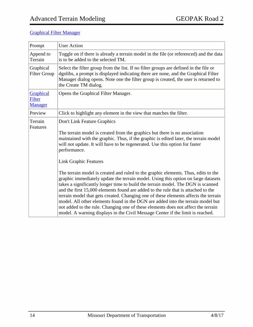
Edit Filter Opens the Edit Filter dialog, wherein you set the parameters for the filter, i.e.,
levels, colors, civil features, etcetera.
Set the parameters by clicking the category to the left, then selecting the parameters.
Define a selection set, select the category, then click By Sel. The software auto-
populates the fields, based on the elements in the selection set. Multiple selections
are supported (Choose six colors or five levels, etcetera.) To view how many
elements match the filter, click Preview. All elements in the view that fit the filter
are highlighted. Once setting the parameters is complete, click Finish to close the
editor and return to the Filter Manager dialog.
Filter By The Filter By section displays at a glance which categories are being specified in
the current filter. For example, if you used level and color to define the filter, the
level and color items are toggled on, once the filter is finished.
Refer to the MicroStation help topic for more information on levels, color, line
weight, line style, and other element attributes.

GEOPAK Road 2 Advanced Terrain Modeling
4/8/17 Missouri Department of Transportation 17
19.7 Group Exercise: Create Terrain by Graphical Filter
The following steps will show the User how to create a Terrain Model of the Proposed Surface
using the Design - Proposed Finished Grade with Boundary Graphic Filter. The Graphic
Filter uses points along the entire proposed finished grade surface which includes but is not
limited to side-slope conditions, top of pavement, top of shoulder, curb, etc. A Terrain Boundary
will also be incorporated that includes the points that make up the Limits of Construction (LOC
points).
1) Open Perry\J9P3093\data\Corridors_J9P3093.dgn
2) Verify the Corridor Design Stage is set to a Final-x 1 for the RTEAC and TG Corridors,
and 1 - Design for the Radius Return Linear Template Drops.
3) Open the Terrain_Proposed_J9P3093.dgn.
a) If needed Delete and Detach everything in the file.
4) Reference in Corridors_J9P3093.dgn (Default 2D View).
a. If needed rotate the view to “Top” and Fit the view.

Advanced Terrain Modeling GEOPAK Road 2
18 Missouri Department of Transportation 4/8/17
5) Select Task > Civil Tools > Terrain Model > Create Terrain by Graphic Filter tool
and choose the following:
a. Graphical Filter Group: Design - Proposed Finished Grade with Boundary
i. Select the Preview Button
ii. Linear Elements in the surface of the Model should highlight.
b. Edge Method: None
c. Feature Definition: Design Triangles
d. Name: Proposed Terrain from Graphic Filter
Note: When the tool is activated the Corridors 3D View is automatically referenced
into the drawing.
6) Notice in the Project Explorer that the Filter Group and Individual Filters were copied
over into the active file.
> Project Explorer
> Civil Standards
> Terrain_Proposed_J9P3093.dgn
> Terrain Filters
7) Detach both references (2D and 3D) to the Corridors_J9P3093.dgn
8) (Optional Step) Select Task > Civil Tools > Terrain Model > Edit Terrain Model tool.
a. Try and edit the Terrain model
Note: The User will notice the Terrain is not editable.
9) Select Task > Civil Tools > General Geometry > Remove Rules tool.
a. Remove the rule to the Terrain Model
b. Using the Edit Terrain Model tools, modify the Terrain Model.
Notes:
Graphic Filters do not have rules back to the original Corridor and
template.

GEOPAK Road 2 Advanced Terrain Modeling
4/8/17 Missouri Department of Transportation 19
19.8 Individual Exercise: Create Terrain by Graphical Filter
The following steps will show the User how to create a Terrain Model of the Proposed Surface
using the Design – Bottom of Base with Boundary Graphic Filter. The Graphic Filter uses
points along the entire proposed finished grade surface which includes but is not limited to side-
slope conditions, top of pavement, top of shoulder, curb, etc. A Terrain Boundary will also be
incorporated that includes the points that make up the Limits of Construction (LOC points).
1) Open Perry\J9P3093\data\Corridors_J9P3093.dgn
2) Review Project setup.
3) Verify the Corridor Design Stage is set to a Final - X 1 for the RTEAC and TG
Corridors, and 1 - Design for the Radius Return Linear Template Drops.
4) Create Terrain_Proposed_J9P3093.dgn using the i_project_3d_PowerGeoPak.dgn as
the seed file.
b) Reference in the Corridors_J9P3093.dgn, Default view.
5) Select Task > Civil Tools > Terrain Model > Create Terrain by Graphic Filter tool
and choose the following:
a. Graphical Filter Group: Design - Proposed Finished Grade with Boundary
i. Select the Preview Button
ii. Linear Elements in the surface of the Model should highlight.
b. Edge Method: None
c. Feature Definition: Design Triangles
d. Name: Proposed Terrain from Graphic Filter

Advanced Terrain Modeling GEOPAK Road 2
20 Missouri Department of Transportation 4/8/17
Note: When the tool is activated the Corridors 3D View is automatically referenced
into the drawing.
6) Notice in the Project Explorer that the Filter Group and Individual Filters were copied
over into the active file.
> Project Explorer
> Civil Standards
> Terrain_Proposed_J9P3093.dgn
> Terrain Filters
7) Detach both references (2D and 3D) to the Corridors_J9P3093.dgn
8) (Optional Step) Select Task > Civil Tools > Terrain Model > Edit Terrain Model tool.
a. Try and edit the Terrain model
Note: The User will notice the Terrain is not editable.
9) Select Task > Civil Tools > General Geometry > Remove Rules tool.
a. Remove the rule to the Terrain Model
b. Using the Edit Terrain Model tools, modify the Terrain Model.

GEOPAK Road 2 Advanced Terrain Modeling
4/8/17 Missouri Department of Transportation 21
19.9 Group Exercise: Create Terrain by Linear Features
1) Open Perry\J9P3093\data\Corridors_J9P3093.dgn
2) Change the Design Stage to Final - Linear Features for all Linear Templates and
Corridors.
3) Select the “F6” key to open the 3D view of the Model.
4) Close the Default 2D view and maximize the 3D view.
5) In the Reference dialog turn off the display of all files.
6) If not already done, use the Level Manager turn off the levels of the non-surface linear
elements
7) Place the remaining linear 3D elements into a MicroStation selection set.
8) Select the Task > Civil Tools > Terrain Model > Create from Elements tool and
choose the following:
9) Using the Element Selection Tool select the Level Modeling-Limits of Construction.
10) Select the Task > Civil Tools > Terrain Model > Change Feature Type tool and
choose the Boundary Option.
11) Open Terrain_Proposed_J9P3093.dgn
12) Delete all elements in file.
13) Reference in the Corridors_J9P3093.dgn, 3D view.
a. Fit the view.
14) In the Level Display dialog turn off all level except for Modeling-Terrain-Proposed and
Modeling-Triangles-Proposed.
a. If the Corridors_J9P3093.dgn, 2D view was automatically referenced in turn off
the display.
15) In the Reference Dialog select the Corridors_J9P3093.dgn, 3D view reference and
select Merge into Master.
Feature Type: Break Line
Edge Method: Remove Slivers
Feature Definition: Design Triangles
Name: Design Triangles from Linear Features

Advanced Terrain Modeling GEOPAK Road 2
22 Missouri Department of Transportation 4/8/17
16) After elements have been merged, detach both references.
17) The element that has been merged is a terrain model but does not have the correct Feature
Definition settings to be a full Civil Terrain Model. To verify this select the terrain and
choose Properties from the heads up tool. You should notice that there is no Feature
Definition applied.
18) To apply a feature definition to the Terrain Elements select Task > Civil Tools >
General Geometry > Set Feature Definition
19) Select Task > Civil Tools > Terrain Model > Edit Terrain Model tool.
a. Try and edit the Terrain model
20) Open Corridors_J9P3093.dgn
21) In the 3D view delete the Terrain Model that was created from the Linear Elements.
22) Select the “F6” key to bring both the 2D and 3D view back.
Feature Type: Surface
Feature Definition: Design Triangles
Name: Design Triangles from Linear Features

GEOPAK Road 2 Advanced Terrain Modeling
4/8/17 Missouri Department of Transportation 23
Note:
If your bottoms of ditches are not showing up as a linear element open the
properties of the Feature Definition XS Ground Proposed and turn on the option
for Create Template Geometry. Once turned ON the User will need to reprocess
the corridor to see the linear elements.