Gearbox for a Wind Turbine - Tsinghua...
132
Gearbox for a Wind Turbine Brendan Speechley Chi Sun Wong Kevin Fan Roshan Khozouei 1
Transcript of Gearbox for a Wind Turbine - Tsinghua...

Gearbox for a Wind Turbine
Brendan Speechley Chi Sun Wong
Kevin Fan Roshan Khozouei
1
2
Executive Summary This report details the design of gearbox for a Wind-Turbine. Our team designed a gearbox with 2 stages, the first stage using a compound epicylic planetary stage with a gear ratio of 1:16.82, followed by a parallel shaft spur gear stage with a gear ratio of 1:4.69. This ensured that the input and output shafts were not coaxially aligned to facilitate the installation of the rotor blade pitch controller. The client requested that the following restraints were met:
Client Requirements Team 20 Gear
Box Design Requirement Surpassed
Height 2.2m 2.14m 0.06m Width 3.3 2.08m 1.22m Length 1.7 1.62 0.08 Efficiency 86.7% 92.96% 6.26% Transmit Power with Gear Ratio of
79.0625 ±1% Error
78.99 0.08% Error
The use of a compound epicylic gear stage enabled us to minimize the weight and therefore the cost of materials used to approximately 5 tonnes (not including the housing). The attached CD contains the solidworks models of the entire gearbox, including the housing, as well as short animations of the operation of the gearbox.

3
TABLE OF CONTENTS 1.0 INTRODUCTION ............................................................................................5
2.0 PROJECT ORGANIZATION ..........................................................................5
3.0 PRELIMINARY DESIGN DATA......................................................................6
4.0 OBJECTIVES AND CRITERIA.......................................................................6
5.0 ENVIRONMENTAL FACTORS ......................................................................7
6.0 OVERALL LAYOUT OF GEARBOX ..............................................................8
7.0 GEAR DESIGN...............................................................................................9
7.1 Gear Design Flow Chart.........................................................................9 7.2 Gear Train Configurations...................................................................10 7.3 Gear Types............................................................................................11 7.4 Gear Stages ..........................................................................................13 7.5 Number of Teeth...................................................................................13 7.6 Resultant Gear Ratios..........................................................................13 7.7 Diametral Pitch .....................................................................................13 7.8 Material Choice.....................................................................................13 7.9 Torque/ Tangential Force Calculation ................................................14 7.10 Hertzian Contact Stress.....................................................................15 7.11 Tooth Bending Stress ........................................................................17 7.12 Gear Face Widths...............................................................................17 7.13 Overall Gear Train Geometry ............................................................18
8.0 SHAFT DESIGN ...........................................................................................19
8.1 Shaft Design Flow Chart......................................................................20 8.2 Shaft Design Results ...........................................................................24 8.3 Sample Calculation ..............................................................................28
9.0 BEARINGS...................................................................................................41
9.1 Selection of bearing type.....................................................................42 9.2 Specification of Bearings ....................................................................43 9.3 Summary of Bearing Specifications:..................................................48 9.4 Other Considerations: .........................................................................48
10.0 SEALS........................................................................................................49
10.1 Seal Selection Flow Chart .................................................................49 10.2 Operating Conditions.........................................................................52 10.3 Operating Conditions of Our Seals...................................................53
11.0 LUBRICATION ...........................................................................................54
11.1 Lubrication of Gears ..........................................................................54 11.2 Lubrication of Bearings .....................................................................56
12.0 GEARBOX HOUSING DESIGN .................................................................57
13.0 HEAT GENERATION & METHODS OF DISSIPATING HEAT ..................58
13.1 Heat Generation Calculation Flow Chart..........................................58

4
13.2 Heat Generation ................................................................................58 14.0 EFFICIENCY..............................................................................................61
14.1 Efficiency Calculation Flow Chart.....................................................61 14.2 Calculated Efficiency .........................................................................69
15.0 VIBRATION CHARACTERISTICS .............................................................70
15.1 Shaft Vibration Analysis Flow Chart.................................................70 15.2 Lateral Vibration Analysis .................................................................71 15.3 Torsional Vibration Analysis.............................................................72 15.4 Vibration Analysis Summary Table ..................................................73
16.0 MANUFACTURE AND ASSEMBLY ..........................................................74
16.1 Gears ...................................................................................................74 16.2 Shafts ..................................................................................................76 16.3 Assembly ............................................................................................78
17.0 FURTHER RECOMMENDATIONS ............................................................79
18.0 CONCLUSION............................................................................................79
19.0 REFERENCES ...........................................................................................80
APPENDIX A – GEARS .....................................................................................82
APPENDIX B- SHAFTS .....................................................................................86
APPENDIX C- BEARINGS...............................................................................102
APPENDIX D -MEETING MINUTES AND DIARIES ........................................103
APPENDIX E – INITIAL APPRECIATION........................................................126
APPENDIX F – ASSEMBLY DRAWINGS........................................................130
APPENDIX G – MATERIAL PROPERTIES .....................................................131
APPENDIX H – SIN DIAGRAM........................................................................132
5
1.0 Introduction Our client is an electrical power generating company, specializing in the production of electrical energy from renewable sources. The company is considering expanding their wind farm capacity with the establishment of a 140 MW wind farm in south-western Victoria. For this facility the client has approached our organization to undertake the detailed design of locally-made gearboxes. This report outlines the design process of the gearbox, including relevant arguments, sketches and calculations made, supported by an accurate, operational Solidworks model, included on the attached CD. The gearbox has been designed using the British Standards Gear Design Standard BS436 (1940), unless otherwise stated. The gearbox design has been taken to the stage where all important decisions have been made. Major areas of investigation include the following:
- Overall layout of gearbox, - Gear design, including materials and dimensions, - Shafts, including stresses, fatigue life, deflections, - Bearings, seals and lubricants, - Gearbox housing design, - Heat generated and methods of dissipating heat, and estimate of
efficiency, - Vibration characteristics of the gearbox and gearing, and - Ease of manufacture and assembly
2.0 Project Organization Attention to the careful management of the project was taken. Detailed planning was conducted, to ensure that there was clear communication between team members, and that the project was on track. A Gantt chart (shown over page) was developed to gauge the progress of the project, and keep the project on track. A weekly review of the project was conducted in comparison to the Gantt chart, and appropriate measures were adopted to ensure the timely progress of the project. Weekly meeting minutes were kept, and each design team member kept a personal design dairy. The use of our design diary in this way allowed us to:
- Keep effective records of all work conducted, - Manage all information and ideas, - Communicate ideas between team members effectively, - Construct design report efficiently, - Ensure timely progress of the project, and - Having all ideas stored in one area ensured that all ideas were
investigated, none were left forgotten. A Strategic Information Network diagram was constructed showing the design strategy adopted, the major decision areas, the interconnecting flows of

information between them and the organization of the project for informed and effective decision making.
3.0 Preliminary Design Data Rotor Type = 3-Bladed, Horizontal Axis (5º Tilt) Rotor Diameter = 62m Rotor Mass = 34 400 Kg Rotor Speed at Peak Output = 19.2 RPM / 12.8 RPM Rotor Shaft Power (Peak) = 1530 kW / 295 kW Generator Shaft Speed (Peak) = 1518 RPM / 1012 RPM Generator Output Power (Peak) = 1300 kW / 250 kW Generator Synchronous Speed = 1500 RPM / 1000 RPM Generator Efficiency = 98% Duty Cycle (Estimated) = High-Speed: 50%; Low Speed
38%; Off:12% Cut-In Wind Speed = 3 m/s Cut-Over Wind Speed = 7 m/s Cut-Out Wind Speed = 25 m/s Full Rated-Power Wind Speed = 15 m/s (approx)
4.0 Objectives and Criteria Objective Criteria
Safety Minimise Accidents No Injuries to Anyone, Ever Maximise Product Performance Minimise Power Loss Maximum Acceptable Power 202kW Maximise Reliability Number of Failures Achieve Step-Up Gear Ratio 79.0625 ± 1.0% Minimise Size 1.7m/ 3.3m/ 2.2m (L/W/H) Minimise Weight Less than 10,000 kg Minimise Operating Vibration Acceleration (m/s2) Seal Performance Gear oil lost over lifetime (mL) Maximise Oil Performance Service Life of oil (Years) Maximise Durability Lifetime of Design 25 years
Resistance to Corrosion No Effect To Operation Over
Lifetime Maximum Operating Temperature 1900c Ease of Manufacture Minimise Number of Parts Number of parts Minimise Assembly Cost Assembly Cost ($) Minimise Manufacturing Cost Manufacturing Cost ($) Minimise Maintenance Minimise Frequency of Maintenance
Time Between Service Intervals (Years)
Transportation Maximise Ease of Transportation Transportation Costs ($) Environmental Impact Accountability
6

Minimise Waste Number of recyclable parts Minimise Noise Loudness (dB) Cost of Disposal Monetary Value ($)
5.0 Environmental Factors The wind turbine will be operating in south-western Victoria. The graph below shows the power/speed characteristics of turbine rotor (blade pitch control). The location of the wind turbine requires us to consider environmental factors influences the material choice and design of the gear box. Since the wind turbine will likely be located in a costal area, we must take this into account in our design our gearbox so that is resistant to corrosion..
1300KW
250KW
0 5 10 15 20
Wind Speed (m/s)
V0
V1
V2 V3
25
Summary of the local wind data: Pr(V<V0) = 12%, Pr(V0<V1) = 38%, Pr(V1<V2) = 47%, Pr(V2<V3) ≈ 3%
7

8
6.0 Overall Layout of Gearbox See appendix A for detailed sketches of the gearbox.

7.0 Gear Design
7.1 Gear Design Flow Chart Brainstorm different gear-train
configurations (Number of Stages, Gear Types, etc..)
Select a design that best meets client specifications
Define number teeth
Determine resultant gear ratios
Define diametral pitch
Calculate gear radii, forces and torques
l
Calcand
De
Determine ocompar
Does
Is the ge
F
No
Select Materia
ulate Hertzian contact tooth bending stress
termine face widths
verall gear train geometry and e with client specifications
it Meet Specifications?
ar-train configuration design optimized?
urther Improvements Yes
Yes
No
9

10
7.2 Gear Train Configurations Simple Gear Train The simplest type of gear-train design transmits rotary motion through parallel shafts. The benefits of such a gear-train are its design simplicity and small number of operating parts. However the overall size and weight of the gearbox is considerably larger than an epicyclic to achieve the same gear ratio. The gear-ratio of a single stage simple parallel shaft gear set is recommended to be between 1:1 and 5:1. Epicyclic Gear Train An epicylic gear is a planetary gear arrangement consisting of one or more planet gears meshed and rotating round a central sun gear. The planet gears are also meshed and rotate within an internal ring gear. The planet gears are fixed to a planet carrier-crank arm designed to rotate on the same axis as the sun gear. Epicyclic gears have the advantage of being compact and lighter than the equivalent parallel shaft arrangement, however more parts are required to operate. Compound Epicyclic Gear Train The compound epicyclic gear unit consists of a central sun gear meshed with three (in our case) planet gears. The planet gears are part of a two-gear cluster on the same shaft or axis as the second planet gears. The second planet gears are then meshed with the ring gear which encloses the system. The planet gears and planet gear support bearings are held in a carrier which rotates about the central axis of the unit. When the ring gear is fixed or grounded and the sun and carrier are input/output members the unit is called a “planetary gear”. The gear-ratio of a single stage compound planetary epicylic gear set is recommended to be between 6:1 and 25:1. Our gear box design incorporates a combination of a compound epicyclic gear train and a simple parallel shaft gear train. It is possible to achieve the required gear ratio using only a single compound epicyclic gear train. As the gearboxes of wind turbine plants are not co-axially designed as a rule, in order to facilitate a central pipe for the rotor blade pitch control, the second stage of the gearbox consists of a spur gear stage, which causes the necessary centre displacement and allows to adjust the output speed to the respective generator speed.

7.3 Gear Types Spur Gears Spur gears are the most common form of gears found in modern gear boxes due to their simplicity and high efficiency. Spur gears are defined as have the length of their gear teeth parallel to the axis of the gear. Spur gears mesh parallel to one another and their mating does not produce any axial thrust.
Simple Helical Gears Helical gears have simhelical gears producesat an angle to the axisHelical gears are smooand specification, and diameters. Helical gealife capabilities than spThe advantages of heloperating speeds and not provide a significan
ilar properties to spur gears however the mating of two an axial thrust, as a result of the axis of their teeth being of the gear. ther and hence quieter that spur gears of the same size are capable of running at high speeds and with large rs also have the advantage of having higher torque and ur gears of the same specification. ical gears however only become significant under high so for the speeds required in our design, helical gears do t benefit over spur gears.
11
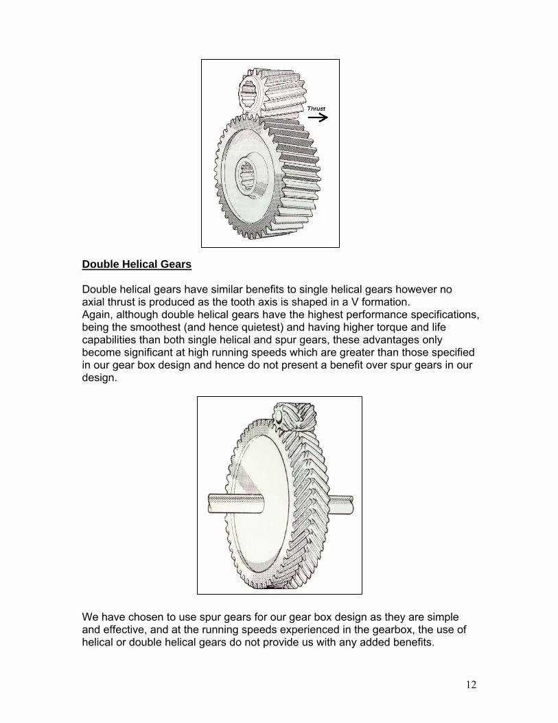
Double Helical Gears Double helical gears havaxial thrust is produced aAgain, although double hbeing the smoothest (andcapabilities than both sinbecome significant at higin our gear box design andesign.
We have chosen to use sand effective, and at the helical or double helical g
e similar benefits to single helical gears however no s the tooth axis is shaped in a V formation. elical gears have the highest performance specifications, hence quietest) and having higher torque and life
gle helical and spur gears, these advantages only h running speeds which are greater than those specified d hence do not present a benefit over spur gears in our
12
pur gears for our gear box design as they are simple running speeds experienced in the gearbox, the use of ears do not provide us with any added benefits.

13
7.4 Gear Stages The overall gear ratio required over the gear-set is 79.0625. As mentioned above although it is possible to achieve this ratio using a series of compound epicyclic gear train, we are making use of an additional spur gear parallel shaft stage in order to offset the output shaft. Given that a compound planetary epicyclic gear stage is capable of achieving a 1:25 gear ratio, and a simple parallel shaft spur gear stage is capable of achieving a 1:5 gear ratio, only two stages were required to achieve the specified gear ratio. It is important to note, that in the planetary gear stage, the input shaft and the output shaft rotate in the same direction. In the case of the parallel shaft stage, the input and output shafts are rotating in opposite directions. This results in the input shaft rotating in the opposite direction to the output shaft of the entire gearbox.
7.5 Number of Teeth After iteration and verification that the number of teeth would mesh, and were capable of assembly the following teeth were chosen: Note: Planet 1 meshes with the ring gear, Planet 2 meshes with the sun gear.
Stage 1 Stage 2
Ring Gear Planet 1 Planet 2 Sun Gear 1 Gear 2
No.of Teeth 117 25 71 21 108 23
7.6 Resultant Gear Ratios The selection of the above teeth numbers, give us a gear ratio of 16.82 in the first stage, and 4.69 in the second stage resulting in an overall gear ratio of 78.99. This is an error of 0.086% which is well with in the allowable range. Calculations are shown in the appendix.
7.7 Diametral Pitch The diametral pitch determines the diameter of the gears, given the number of teeth. Thus, the diametral pitch was chosen to ensure that the resultant gear diameters comfortably fitted into the housing. For the above gear diameters a diametral pitch of 2.25 was found to be optimal.
7.8 Material Choice It was determined that Nickel-Chromium Low alloy steel, AISI 4340 (tempered @ 205 C, oil quenched), was the most economical and robust material for use in the gearbox. Full details of the material is attached in Appendix.G

7.9 Torque/ Tangential Force Calculation The torque being transferred through each gear was calculated using the following equation:
ocityAngularVelPowerTorque =
The peak power input from the rotor is given as 1530 kW, rotating at a speed of 19.2 rpm. Thus
761.19kNm2.011530eInputTorqu ==
This torque is then shared among the three planetary gears and is acting at a distance equivalent to the radial arm from the central axis to axis of the planetary gear. Thus the torque at the planets is equal to
50.91kNm0.23
761.19uePlanetTorq =×=
The tangential force is then calculated using the following equation:
radialtnagential DistForceTorque ×=
0.14111Force50.91 tnagential ×= 361.2587kN11150.91/.014Forcetnagential ==
This process has been repeated throughout the gear train to calculate the torques and tangential forces acting on each gear. The table below lists the required values and dimensions and the calculated torques and forces acting on each gear.
14

Torque and Force Calculations Power In 1530 kW Torque In 760.95957 kNm First Stage Number of Planets 3 Gears Radius of R 0.6604 m Radius of P1 0.1411111 m Radius of P2 0.4007556 m Radius of S 0.1185333 m Torque.Arm 760.95957 kNm Torque.P1 50.977628 kNm Torque.P2 -50.97763 kNm Torque. Sun 45.23367 kNm Force.Ring 361.25878 kN Force.P1 361.25878 kN Force.P2 127.2038 kN Force.Sun 127.2038 kN Second Stage Radius of S1 0.6096 m Radius of S2 0.1298222 m Torque S1 45.23367 kNm Force.S1 74.202215 kN Force.S2 74.202215 kN Torque.S2 9.6330964 kNm
7.10 Hertzian Contact Stress The Hertzian stress was calculated using the following formulae:
Where Ft is the tangential force acting on the gear tooth.
Sc is a material property known as the surface stress factor and was determined according to BS 436 (Appendix A ) Xc is the speed factor and is determined according to BS436 (See chart 11 Appendix A ) K is the pitch factor determined according to BS 436 (See chart 12 Appendix A) Z is known as the zone factor and is determined according BS 436 (See chart 8 Appendix A) b is the gear tooth width.
Calculating Equivalent Running Time Before we were able to determine the speed factor we were first required to calculate the equivalent running time of the gear box.
15
This is due to the unsteady loading of the gear box which requires us to calculate an equivalent running time at a uniform load which would have the same effect on the gears.

If the load cycle comprises of a maximum sustained wheel or pinion torque (M1) acting for (U1) hours, at a mean speed (N1), and smaller sustained torques (M2, M3, etc) acting for U2,U3, etc hours at mean speeds N2, N3, etc, the equivalent running time at the maximum sustained load and the corresponding mean speed is given by :
etcMM
NNU
MM
NNUU +⎟⎟
⎠
⎞⎜⎜⎝
⎛⎟⎟⎠
⎞⎜⎜⎝
⎛+⎟⎟
⎠
⎞⎜⎜⎝
⎛⎟⎟⎠
⎞⎜⎜⎝
⎛+
3
1
3
1
33
3
1
2
1
221
in which each term represents the equivalent running time for the corresponding period. If during any period (w) the torque changes uniformly from Mw1 to Mw2, the expression for the equivalent running time for that period is given by
⎥⎥⎦
⎤
⎢⎢⎣
⎡⎟⎟⎠
⎞⎜⎜⎝
⎛+⎟⎟
⎠
⎞⎜⎜⎝
⎛⎥⎦
⎤⎢⎣
⎡+⎟⎟
⎠
⎞⎜⎜⎝
⎛2
1
2
2
1
12
1
1
1 14 MM
MM
MM
MM
NNU wwwwww
The gears should be designed to transmit a uniform load M1 at uniform speed N1 for the sum of the equivalent running times calculated this way.1Using the above equation we calculated our total uniform running time to be 3.84 hours. Mnimum Face Width to Withstand Hertzian Contact Stresses. Substituting the values into the above Hertzian Stress equation, and then solving for b allowed us to determine the minimum tooth width required to withstand the Hertzian contact stress developed on the face of the gear tooth during operation. The table below lists the values of the required variables for each gear pair mating as well as the minimum calculated gear tooth width required to withstand the Hertzian contact stress.
Mating A Mating B Mating C
Ring Gear Planetary
Gear Planetary
Gear Sun GearSpur Gear
1 Spuir Gear 2
Number of Teeth
117 25 71
21
108 23 Zone Factor (Z) 3.679 3.679 2.200 2.200 2.450 2.450 Speed Factor
(Xc) 0.650 0.650 0.550 0.550 0.390 0.390 Sc 8000.000 8000.000 8000.000 8000.000 8000.000 8000.000
Ft (lbs) 81213.865 81213.865 28596.431 28596.431 16681.252 16681.252 Factor of Safety 1.000 1.000 1.000 1.000 1.000 1.000 Pitch Factor (K) 2.250 2.250 2.250 2.250 2.250 2.250
D (in) 52.000 11.111 31.556 9.333 48.000 10.222 Diameter (cm) 132.080 28.222 80.151 23.707 121.920 25.964
Ouside Diameter 172.080 b (in) 9.551 9.551 6.647 6.647 4.910 4.910
16
1 Referenced from BS436 Clause 65

17
b (mm) 242.588 242.588 168.831 168.831 124.717 124.717
7.11 Tooth Bending Stress The tooth bending stress was calculated using the following formulae:
Where Ft is the tangential force acting on the gear Sb is the bending stress factor, a material property determined by BS436 (See appendix A) Xb is the speed factor determined by BS436 (See chart 10 Appendix A) Y is the strength factor determined by BS436 (See chart 9 Appendix A) P is the diametral pitch b is the minimum tooth face width to withstand bending stress.
Similar to the Hertzian stress calculation, the equivalent running is required to calculate the value of Xb The table below lists the values of the above variables and the resultant value of the minimum face width to withstand the bending stress at the root of the tooth.
Mating A Mating B Mating C Ring Gear Planetary Gear Planetary Gear Sun Gear Spur Gear 1 Spuir Gear 2
No. of Teeth 117 25 71 21 108 23 Strength Factor
(Y) 0.757 0.757 0.718 0.718 0.741 0.741 Speed Factor
(Xb) 0.500 0.500 0.410 0.410 0.290 0.290 Sb 49500.000 49500.000 49500.000 49500.000 49500.000 49500.000
Ft (lbs) 81213.865 81213.865 28596.431 28596.431 16681.252 16681.252 Factor of Safety 1.000 1.000 1.000 1.000 1.000 1.000
Diametral P 2.250 2.250 2.250 2.250 2.250 2.250 D (in) 52.000 11.111 31.556 9.333 48.000 10.222
Diameter (cm) 132.080 28.222 80.151 23.707 121.920 25.964 Ouside Diameter 172.080
b (in) 9.760 9.760 4.416 4.416 3.528 3.528 b (mm) 247.892 247.892 112.154 112.154 89.624 89.624
7.12 Gear Face Widths As advised by Mr Weir, a factor of safety was not applied to the Hertzian Contact stress of Tooth bending stress as the tables and charts used in the calculation of these stresses incorporated the factor of safety within them. The calculated stresses were compared to determine which stress type required the largest face width. The table below shows that for all but the ring and planet gear 1, the Hertzian stress was more significant. In the case of the ring and planet gear 1,

18
the two stresses, were nearly equal in significance. The table below shows the resultant face widths.
Hertzian and Bending Stresses Hertzian: Minimum Face Width Ring and Planet 1 Gears 242.588 mm Planet 2 and Sun Gears 168.8312 mm Stage 2 Spur Gear 1 & 2 Set 124.71658 mm Bending: Minimum Face Width Ring and Planet 1 Gears 247.89187 mm Planet 2 and Sun Gears 112.15395 mm Stage 2 Spur Gear 1 & 2 Set 89.623822 mm Overall: Minimum Face Width Ring and Planet 1 Gears 247.89187 mm Planet 2 and Sun Gears 168.8312 mm Stage 2 Spur Gear 1 & 2 Set 124.71658 mm
7.13 Overall Gear Train Geometry The overall gear train geometry was calculated modeling each gear as a cylinder to determine the spatial characteristics below. As can be seen, the overall gearbox height and width is 1.84m which fits easily into the spatial requirements. A preliminary internal length of the gearbox, prior to shaft, and assembly considerations is under 0.6m which is well short of the maximum length.
Spatial Constraints Overall Gear Box Width 1840.0889 mm Overall Gear Box Height 1840.0889 mm Overall Gear Box Length 595.58361 mm Ring Gear Mass 1357.3258 kg Planet 1 Gear Mass 122.50721 kg Planet 2 Gear Mass 672.95927 kg Sun Gear Mass 58.872255 kg Stage 2 Spur Gear 1 1150.2469 kg Stage 2 Spur Gear 2 52.167404 kg Total Mass 5005.0119 kg Location of input shaft Centre of Nacelle Location of output shaft 0.739 m vertical displacement

8.0 Shaft Design The scope of shaft design in this gearbox consists of the shafts within the gearbox as well as the main shaft linking the rotor to the gearbox. From the gear configuration specified earlier, six shafts are required within this gearbox to transmit the wind power to the appropriate operating speed for the generator. The six shafts required are illustrated schematically below.
0. Main Input Shaft
1. Intermediate Input Shaft
2,3,4. Planetary Shafts (x3)
Stage 1
5. Output Shaft Stage 1
6. Output Shaft Stage 2
Output Speed: 1518 RPM
Input Speed: 19.2 RPM
19

8.1 Shaft Design Flow Chart
20
In designing shafts for this gearbox, the flow chart shown above will be followed.
Identify Forces& Torque Acting on Shaft
Determine Max Moment
Draw SFD and BMD
Determine Shape Factors
Use AS1403 DEFP to find
min. allowable shaft diameter
Select Material
Shaft Diameter bigger than pitch
diameter of smallest gear?
Determine the max deflection and min. Shaft
diameter
Choose larger diameter
NO YES
Step Shafts Finish
Determine Length of Shaft
Here the design variables are
• Length of Shafts • Material of Shafts
21
• Diameter of Shafts Determining Length of Shaft
Length of shafts would be most influenced by the
1. Calculated minimum gear widths 2. Need for bearings to support the shafts 3. Clearances to allow for lubrication within parts, hence minimising
frictional contact. 4. Size constraints of the gearbox in the Wind Turbine
With all these factors taken into account, a rough layout of the gearbox can be visualized and hence the shaft lengths can be estimated.
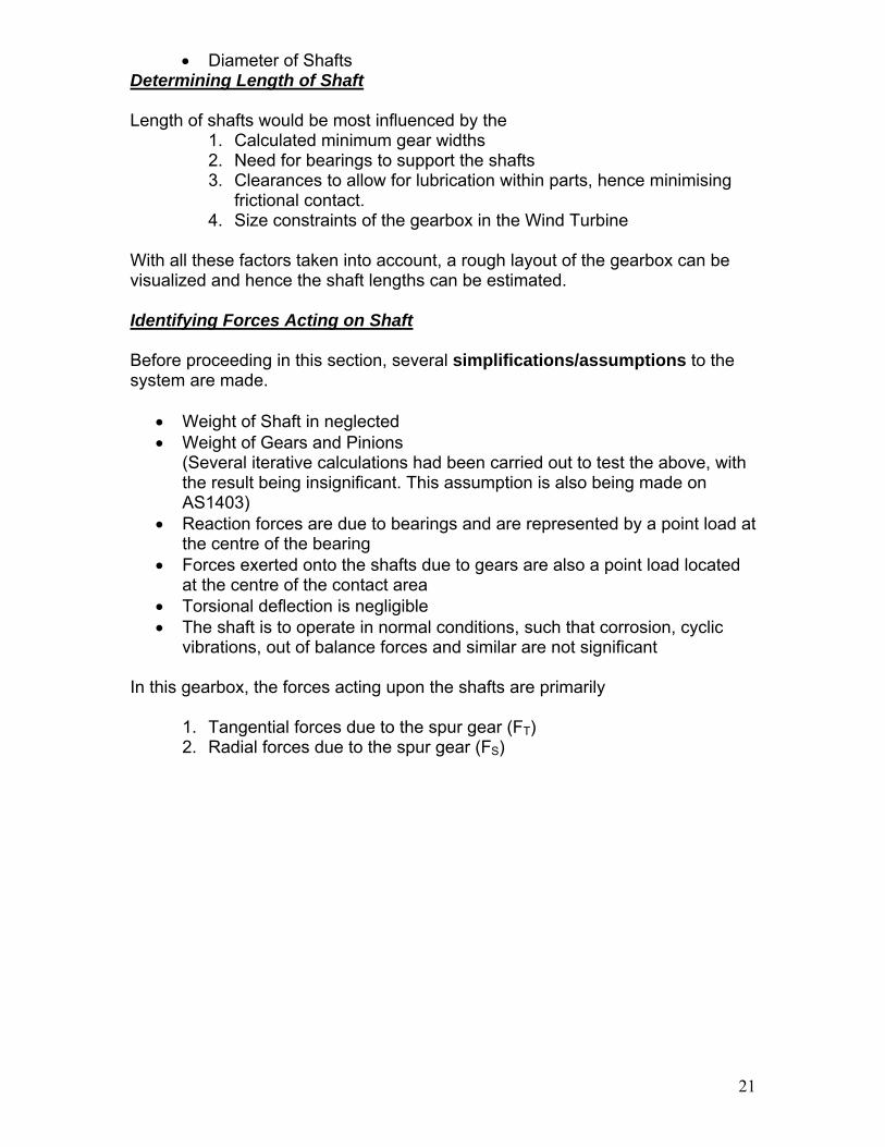
Identifying Forces Acting on Shaft Before proceeding in this section, several simplifications/assumptions to the system are made.
• Weight of Shaft in neglected • Weight of Gears and Pinions
(Several iterative calculations had been carried out to test the above, with the result being insignificant. This assumption is also being made on AS1403)
• Reaction forces are due to bearings and are represented by a point load at the centre of the bearing
• Forces exerted onto the shafts due to gears are also a point load located at the centre of the contact area
• Torsional deflection is negligible • The shaft is to operate in normal conditions, such that corrosion, cyclic
vibrations, out of balance forces and similar are not significant In this gearbox, the forces acting upon the shafts are primarily
1. Tangential forces due to the spur gear (FT) 2. Radial forces due to the spur gear (FS)
xy
z
FT
FS
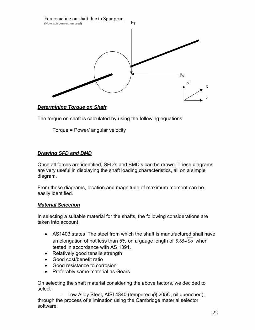
Forces acting on shaft due to Spur gear. (Note axis convention used)
Determining Torque on Shaft The torque on shaft is calculated by using the following equations:
Torque = Power/ angular velocity
Drawing SFD and BMD Once all forces are identified, SFD’s and BMD’s can be drawn. These diagrams are very useful in displaying the shaft loading characteristics, all on a simple diagram. From these diagrams, location and magnitude of maximum moment can be easily identified. Material Selection In selecting a suitable material for the shafts, the following considerations are taken into account
• AS1403 states ‘The steel from which the shaft is manufactured shall have an elongation of not less than 5% on a gauge length of So65.5 when tested in accordance with AS 1391.
• Relatively good tensile strength • Good cost/benefit ratio • Good resistance to corrosion • Preferably same material as Gears
On selecting the shaft material considering the above factors, we decided to select
- Low Alloy Steel, AISI 4340 (tempered @ 205C, oil quenched),
22
through the process of elimination using the Cambridge material selector software.

23
de Prediction Failure Mo
loading and the primary failure modes are
Fatigue failure
To address these failure modes, it is convenient to utilise a failure predictor. In
is design, we shall use DEFP ‘Distortion Energy Predictor’ since it is more
Shafts undergo multi-axial
• Yielding due to excessive loads •• Excessive deflection
thaggressive than the MSFP approach. Refering to AS1403 – 2004, the appropriate formula to determine the minimum shaft diameter is as follows.
Where D = Minimum shaft diameter/ Trial Diameter
FS = Safety Factor
ial Tensile Force
he above equation will address yielding and fatigue.
icant compared to the ther two. However consequences due to deflection can cause excessive wear in
ble to state that deflection should e not more than 5% of gear tooth height, which equates to
FR = Endurance Limit of Material KS = Size Factor K = Stress Rasing Factor Pq = Maximum Ax Tq = Maximum Torque T As for deflection, this is factor is perhaps not very signifogears, buckling of shafts if the shaft is excessively long and wear out bearings. Hence we will still consider this in this design. Based on the gear design, it would be reasonab ±
mmall 22.2<δ
here is also a maximum allowable deflection limit on bearings (see Bearings ection), however we shall take the above constraint as it is the worst case.
all
e calculated iameters are not bigger than the pitch diameter of the smallest gear on the shaft.
nger
TSAt this stage, we should have produced two ‘minimum diameters’, hence we shchoose the higher diameter of the two as our specification. As indicated on the flow chart, we also need to check that thdIn which case, there’s no choice but to re-iterate the procedure with a stromaterial until the condition is satisfied.

24
tep Shafts
S
t a uniform diametrical shaft is not practical when assembling the earbox, hence we will introduce some steps in the shaft design to ease the
minimum diameter is found, we will step down the shafts at reas with a lower load to incorporate a step. These steps will be designed by
.2 Shaft Design Results
Number me Worst case min.
diameter (DEFP) Min. Diameter for
allowable deflection
We realise thagassembly process. Once the worst caseaanalysing the load distribution along the shaft and employing DEFP at the appropriate positions (Taking into account stress raising characteristics such asnotch effects)
8
Shaft Shaft Na
(mm) (mm) 0. Main Input Shaft 741 400 1. Intermediate Input No N ding
Shaft 359 et Ben
2,3,4. Planetary Shaft 213 112 5. Output Shaft Stage 1 164 22 6. Output Shaft Stage 2 100 22
• ence d nt in all
Sh
Shaft 1 - Intermediate Input Shaft
H eflection is not significa cases
aft 0 - Main Input Shaft
741
Features • Female spline connection (H7-k6) to Intermediate Input Shaft
Connection to Rotor
359

25
Shaft 5 - Output Shaft Stage 1
Shafts 2,3,4. - Planetary Shafts
213
140 497 140
150
Features ay on opposite sides) connection to
Planetary and Sun gear • Step down feature at shaft ends to accommodate bearing fitment
• H7-s6 (side-milled keyw
365
100 100 100 100
359
Features • Male spline H7-k6 connecting into Main Input Shaft • H7-s6 Keyway connection to connect to planetary gear plate • Step-Up feature to accommodate spline and bearing fitment

Shaft 6 - Output Shaft Stage 2
26
100
100 125 100
75
Features • H7-s6 (side-milled keyway on opposite sides) connection to
output spur gear • Step down feature at shaft ends to accommodate bearing fitment
700 Features
• H7-s6 (side-milled keyway on opposite sides) connection to Sun Gear and Output Spur Gear
• Step down feature at shaft ends to accommodate bearing fitment
500
129 164

27

8.3 Sample Calculation (See Appendix for details and calculation of other shafts) Planetary Shaft 1) Length of Shaft
Width of Planetary Gear 1 = 248mm Width of Planetary Gear 2 = 169mm
50 264
553
627
677
248
169
2) Force Analysis X-Y Plane FBD
L1 L2
L3
FS1
FS2R1 R2
∑ = 0M , R1 x L3 + FS2 (L3-L2) = FS1 x (L3-L1) 28
=> 3
)23()13( 211
LLLFLLFR SS −−−
=
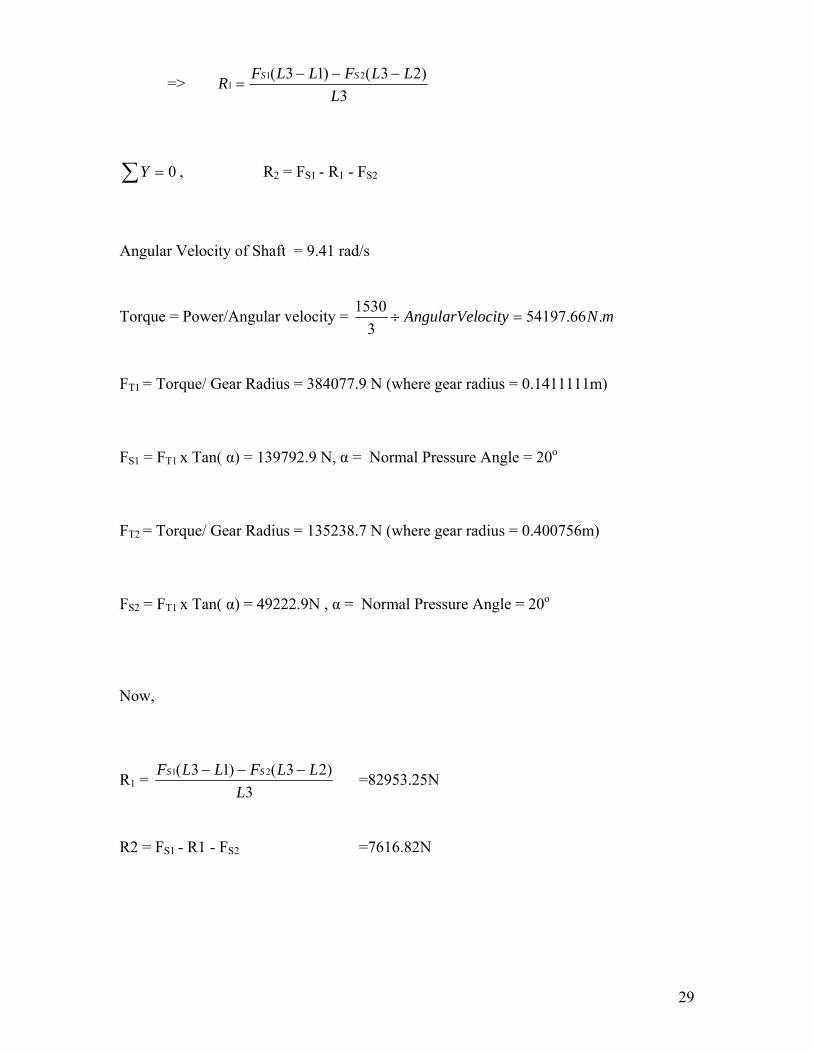
∑ = 0Y , R2 = FS1 - R1 - FS2
Angular Velocity of Shaft = 9.41 rad/s
Torque = Power/Angular velocity = mNocityAngularVel .66.541973
1530=÷
FT1 = Torque/ Gear Radius = 384077.9 N (where gear radius = 0.1411111m) FS1 = FT1 x Tan( α) = 139792.9 N, α = Normal Pressure Angle = 20o
FT2 = Torque/ Gear Radius = 135238.7 N (where gear radius = 0.400756m) FS2 = FT1 x Tan( α) = 49222.9N , α = Normal Pressure Angle = 20o
Now,
R1 = 3
)23()13( 21
LLLFLLF SS −−− =82953.25N
R2 = FS1 - R1 - FS2 =7616.82N 29
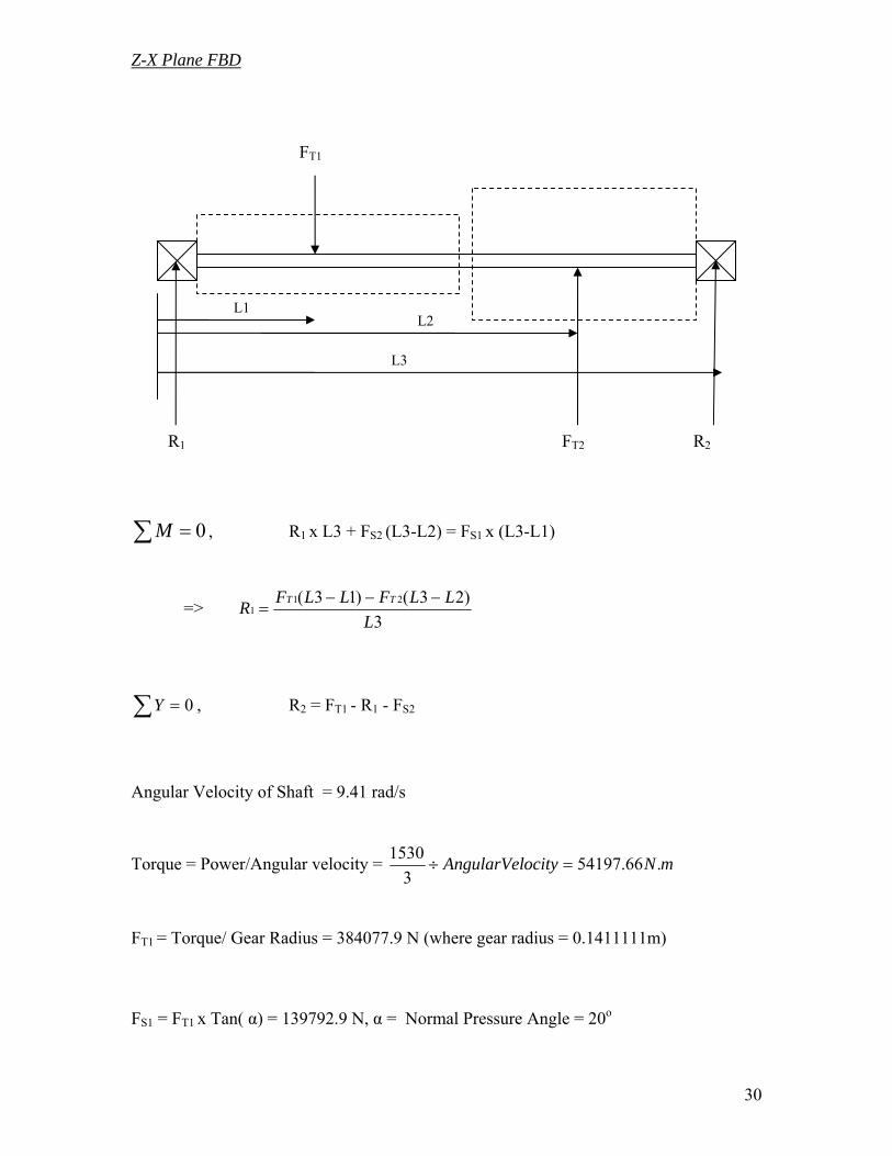
Z-X Plane FBD
L1 L2
L3
FT1
FT2R1 R2
∑ = 0M , R1 x L3 + FS2 (L3-L2) = FS1 x (L3-L1)
=> 3
)23()13( 211
LLLFLLFR TT −−−
=
∑ = 0Y , R2 = FT1 - R1 - FS2
Angular Velocity of Shaft = 9.41 rad/s
Torque = Power/Angular velocity = mNocityAngularVel .66.541973
1530=÷
FT1 = Torque/ Gear Radius = 384077.9 N (where gear radius = 0.1411111m) FS1 = FT1 x Tan( α) = 139792.9 N, α = Normal Pressure Angle = 20o
30

FT2 = Torque/ Gear Radius = 135238.7 N (where gear radius = 0.400756m) FS2 = FT1 x Tan( α) = 49222.9N , α = Normal Pressure Angle = 20o
Now,
R1 = 3
)23()13( 21
LLLFLLF TT −−− =227912.18N
R2 = FS1 - R1 - FS2 =20927.04N 3) Draw SFD and BMD X-Y Plane
537
174
-
+
82953.25N 7616.82N
400
49222.9N
139792.9 N
82953.25N
7616.82N
56839.65N 31

Analysing Moments on Shaft
32
For x< L1 M(x) = R1(x) For L1<x<L2 M(x) = R1(x) – FS1(x-L1) For L2<x<L3 M(x) = R1(x) – FS1(x-L1) + FS2(x-L2) Bending Moment Diagram for Planetary Shaft in X-Y Plane
L1 L2
x
FS1
FS2R1
+
MMAX (X-Y) = 14433.87N.m
L1

Z-X Plane
33
Analysing Moments on Shaft
L1 L2
x
FS1
FS2R1
537
174
-
+
227912.18N 20927.04N
400
135238.7 N
384077.9 N
227912.18N
20927.04N
156165.72N
For x< L1
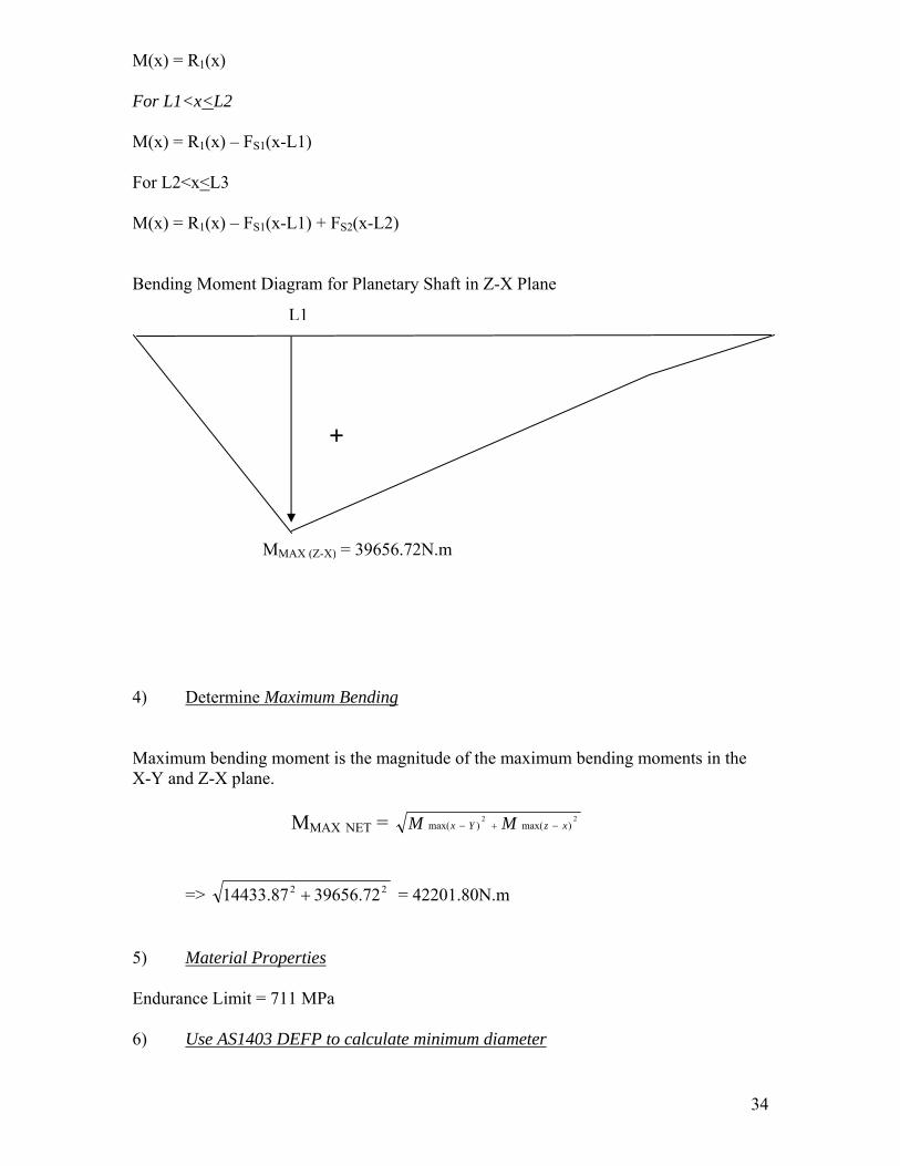
M(x) = R1(x) For L1<x<L2 M(x) = R1(x) – FS1(x-L1) For L2<x<L3 M(x) = R1(x) – FS1(x-L1) + FS2(x-L2) Bending Moment Diagram for Planetary Shaft in Z-X Plane 1
M
4) Determine M Maximum bending mX-Y and Z-X plane.
=> 14433.8 5) Material Prop Endurance Limit = 7 6) Use AS1403 D
L
+
MAX (Z-X) = 39656.72N.m
aximum Bending
oment is the magnitude of the maximum bending moments in the
MMAX NET = 22)max()max( xzYx MM −+−
22 39656.727 + = 42201.80N.m
erties
11 MPa
EFP to calculate minimum diameter
34

Fs = 2 (As stated by AS1403) Fr = 711 Ks = 1.7 (Obtained from Figure 1 of AS1403) K = 4 (Obtained from Figure 7 of AS14013 due to keyway) Mq = 41685.86 (Max. Moment) Pq = 0 (No axial tensile load – Spur Gear) Tq = 54197.66 (Torque on shaft)
D = 212.3456mm For manufacturing feasibility allowance, we will round this up to 212mm. This diameter is smaller than the gear diameter of 283mm. So OK. 7) Calculate minimum diameter due to deflection Deflection of the shaft is primarily due to bending. On this shaft, there are two forces causing bending (FT and FS) and deflection on each will be analysed individually and summed up using the principal of superposition.
FT
FSY
Z
The plane of maximum loading can be represented by:
35
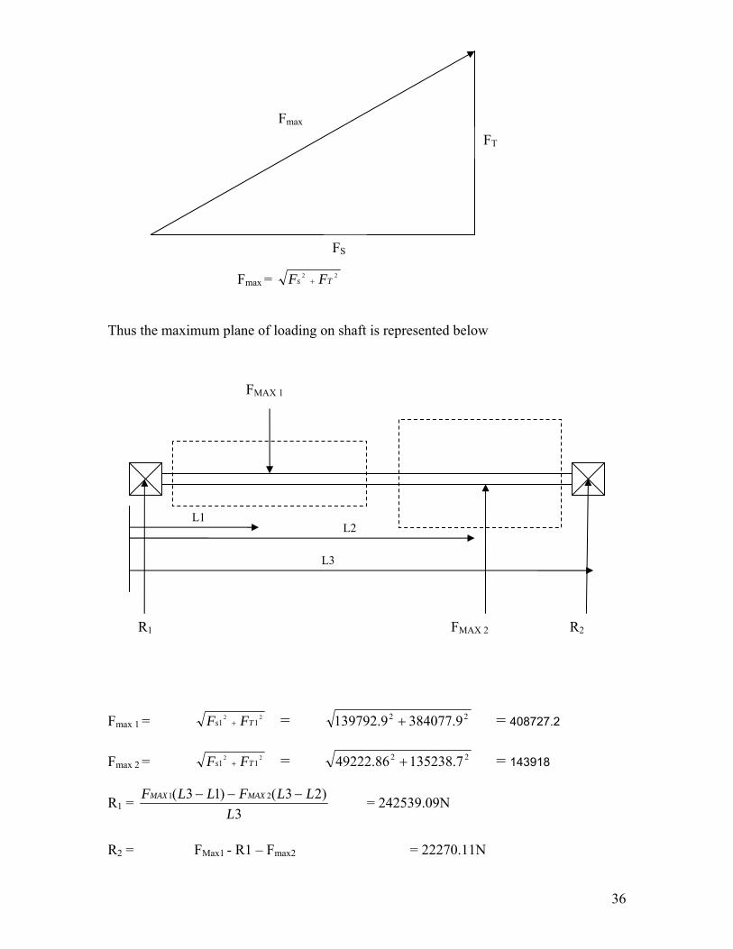
FS
FT
Fmax
Fmax = 22
Ts FF + Thus the maximum plane of loading on shaft is represented below
L1 L2
L3
FMAX 1
FMAX 2R1 R2
Fmax 1 = 22
11 Ts FF + = 22 384077.9139792.9 + = 408727.2 Fmax 2 = 22
11 Ts FF + = 22 135238.749222.86 + = 143918
R1 = 3
)23()13( 21
LLLFLLF MAXMAX −−− = 242539.09N
R2 = FMax1 - R1 – Fmax2 = 22270.11N
36

Now using the double integration method, Considering effect of FMAX 1 only, M(x) = R1x – FMAX 1(x-L1) EIy” = M(x) EIy” = R1x – FMAX 1(x-L1)
EIy’ = ( ) 1122
212
1 CLxFxR MAX +−−
EIy = ( ) 21166
313
1 CxCLxFxR MAX ++−−
When x=0, y=0 => C2 =0 When x= L3, y=0
0 = ( ) 311366
3 313
1 LCLLFLR MAX ×+−−
Therefore C1 = ( ) ⎟⎟⎠
⎞⎜⎜⎝
⎛−+
− 313
1 1366
33
1 LLFLR
LMAX
EIy = ( )313
1 166
LxFxR MAX −− + ( ) xLL
FLRL
MAX⎟⎟⎠
⎞⎜⎜⎝
⎛−+
− 313
1 1366
33
1
Considering effect of FMAX 2 only, M(x) = -R1x + FMAX 2(x-L2) EIy” = M(x)
37

EIy” = -R1x – FMAX 2(x-L2)
EIy’ = ( ) 1222
222
1 CLxFxR MAX +−+−
EIy = ( ) 21266
323
1 CxCLxFxR MAX ++−+−
When x=0, y=0 => C2 =0 When x= L3, y=0
0 = ( ) 312366
3 323
1 LCLLFLR MAX ×+−+−
Therefore C1 = ( ) ⎟⎟⎠
⎞⎜⎜⎝
⎛−+ 32
31 23
663
31 LL
FLRL
MAX
EIy = ( )323
1 266
LxFxR MAX −+− + ( ) xLL
FLRL
MAX⎟⎟⎠
⎞⎜⎜⎝
⎛−− 32
31 23
663
31
Using MATLAB to compute equation and impose superposition, we can visualise the point where maximum deflection occurs.
38

At the same time, we can calculate the ‘maximum’ minimum diameter of the shaft, taking 2.22mm as the maximum allowable deflection as stated earlier.
From the previous chart, we see that the ‘maximum’ minimum diameter is about 112mm, which is way below the estimated 213mm.
39

Hence we acknowledge deflection is negligible compared to failure due to yielding and fatigue and we take 213mm as the specified diameter of the Planetary Shaft. Assembly/ Servicing Considerations In determining a safe step size for the Planetary Shaft, analyses of loading on each point of the shaft is performed and arrive to the conclusions.
• The maximum bending occurs at the gears, hence the diameter of that area is suggested to be kept at the worst case minimum diameter of 176mm.
• At the bearing locations, bending is minimal. Hence we can step down the size here. Taking into account the bending and the torque through this area, we calculate to be 148mm (via the above methods, taking into account the notch stress raising factors, bearing effects of AS1403).
Use AS1403 DEFP to calculate minimum diameter
Fs = 2 (As stated by AS1403) Fr = 711 Ks = 1.7 (Obtained from Figure 1 of AS1403) K = 2.2 (Obtained from Figure 5 of AS14013 due to bearing, Notch effect is
negligible due to distance between stress raising factors > 0.25 D) Mq = 5989.35 (Max. Moment at x=25mm) Pq = 0 (No axial tensile load – Spur Gear) Tq = 54197.66 (Torque on shaft)
D = 147.23mm Hence use 148mm, but to accommodate bearing availability, specify 150mm. (See Bearings section for details)
Furthermore, the gear and shafts needs to be mated to transfer torque.
• Side-milled keyway on opposite sides H7-k6 (Transition Fit) is incorporated.
212mm
Keyway Feature
148mm
40
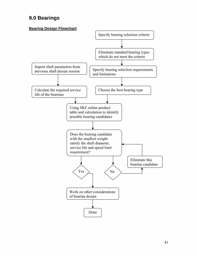
9.0 Bearings Bearing Design Flowchart
Specify bearing selection criteria
Choose the best bearing type
Eliminate standard bearing types which do not meet the criteria
Import shaft parameters from previous shaft design session
No
Work on other considerations of bearing design
Specify bearing selection requirements and limitations
Calculate the required service life of the bearings
Using SKF online product table and calculation to identify possible bearing candidates
Yes
Does the bearing candidate with the smallest weight satisfy the shaft diameter, service life and speed limit requirement?
Done
Eliminate this bearing candidate
41

42
9.1 Selection of bearing type1
Each bearing type displays characteristic properties, based on its design, which makes it more, or less, appropriate for a given application. A comprehensive overview of the standard bearing types is presented in APPENDIX C, which gives the design characteristics and suitability for different given applications. In the current application of a wine turbine, several factors have to be considered and weighted against each other while selecting an appropriate standard bearing type. The factors of considerations are following: Misalignment (hurdle criteria) The shaft diameters in the previous sessions are designed with small allowable deflection based on gear tolerance. The resulting effect of this on bearing is causing the problem of misalignment between the outer and inner rings of a bearing. Therefore, those standard bearing type with a “-“or worse rating in column 15 of APPENDIX C should be eliminated. Axial displacement (hurdle criteria) In the current application, ALL bearings must not permit shaft movement in the axial direction. Therefore, those standard bearing type with a “+“or “+++” in column 19 of APPENDIX C should be eliminated. Loads (hurdle criteria) In the current application, all bearings are required to withstand heavy radial loads. According to column 7 of APPENDIX C, those bearing types which purely support axial load should be eliminated. Available size (limitation) One of the principal dimensions of a bearing - the bore diameter - is predetermined by the shaft diameter. For large-diameter shafts, cylindrical, taper, spherical and toroidal roller bearings and deep groove ball bearings should be used. Speed (requirement/limitation) The permissible operating temperature limits the speed at which rolling bearings can be operated. Bearing types with low friction and correspondingly low heat generation are recommended for shafts rotating at a relative high speed, as indicated in Column 10. Quiet running (requirement) The noise in operation is not an serious concern in the current application, but it is still a factor under consideration (Column 13) Base on above considerations, APPENDIX C and the shaft parameters calculated in last session (see Table B1), the only chosen bearing types is spherical roller bearing as showed below( see Figure B1). 1 Reference: Hwww.skf.com

Table B1
Shaft Number
Max Applied Radial Load (kN)
Shaft diameter (mm)
Angular Velocity (rpm)
Required life (million rev)
Chosen Bearing Type
0 528.894 741 19.2 35.26028
Spherical roller bearing
1 None 359 19.2 35.26028 Not required 2,3,4 23.71336 150 89.9 164.9921 5 36.93621 129 323.0 593.0663 6. 40.66281 75 1516.7 2784.832
Spherical roller bearing
The main reason to justify this choice is that, spherical roller bearings can carry very heavy radial loads and allows small shaft deflections; it can withstand a misalignments angle of at least 1.5º between the outer and inner ring.
Figure B1 - roller bearings
9.2 Specification of Bearings The SKF website provides bearing product tables and online calculator for equivalent bearing loads and rating life. These are extremely useful and practical tools, which make engineers’ life much easier! Followings are the steps to select the right specifications of the Shaft 6: Step 1: Identify the available bearings with appropriate principle diameter. In this case, 75mm is the one to choose.
43

Step 2: In order to minimize cost, the selection starts with the 75mm spherical roller bearings with the smallest weight. i.e. 24015 CC/W33 with width B=40mm Step 3: By inputting the applied radial load Fr= 40.66281kN and the following result is produced:
The result shows that bearing 24015 CC/W33 will have L10 =basic rating life = 120 millions of revolutions, which does NOT satisfy the required service life of 2784.832 millions of revolutions.
44

Step 4: Repeat Step 2 & 3 for the next heavier bearing on the product table until the one which is able to satisfy the required service life. The final bearing selected is BS2-2315-2CS and its specification is shown below:
45

For Shaft 6:
The other bearings are selected in a similar way and the specifications of the selected bearings are listed below: For Shaft 0:
46

For Shaft 2,3,4:
For Shaft 5
47

9.3 Summary of Bearing Specifications:
Shaft Number
Bearing selected Bore Diameter(mm)
Outer Diameter(mm)
Width(mm)
0 238/750 CAKMA/W20
750 920 128
1 Not required - - - 2,3,4 23030 CC/W33 150 225 58 5 23026 CC/W33 130 200 52 6. 238/750
CAKMA/W20 75
160 55
9.4 Other Considerations: The fitting between the shafts and bearings required some turning of the shafts. It is recommended that the turning achieves a Transition Fit of K6H6. This is because that an interference fit are likely to break the bearing and a loose fit will keep the shaft spinning. The lubricant is an essential component of the bearing arrangement. It has to prevent wear and protect against corrosion so that the bearing can deploy its full performance. In addition, the seal of the bearings required careful attentions. Any leak may potentially pollute the lubricant and un-cleanliness has a vital effect on bearing service life. In order to prevent axial displacement, the bearings should be always mounted with an Interference fit directly to the housing or to arms attached to the housing.
48

10.0 Seals
10.1 Seal Selection Flow Chart
Research different types of seals available for rotary shafts
Determine operating conditions of seal
Determine main objective of seal
Choose seal type from those available that best fits our needs and can operate in defined operating conditions
There are generally 5 main types of seals used on rotating shafts 1. Labyrinth Seals 2. Felt Seals 3. Lip Seal 4. Ferro Fluid Seals 5. Mechanical seals Labyrinth Seals: This seal restricts the passage of solid, liquid and gas contaminants into the sealed area and also restricts the leakage of fluid out of the sealed container. Non-contact rotary and stationary elements provide a restricted flow path and make use of centrifugal force and gravity to prevent leakage. The advantage of the labyrinth seal is that is unlike other rotating lip seals , it will not damage the shafts, has a virtually unlimited life, is frictionless, is largely unaffected by high or low temperatures and can be used for high shaft rotating speeds. The obvious disadvantage of this type of seal is the presence of an engineering gap. Hence this seal does not work well under extreme pressure differences and for low shaft speeds. This seal is somewhat excessive for our needs. Felt Seals Felt seals are mainly used as oil or grease seals for retaining lubrication while simultaneously preventing dirt or dust from entering the bearing. The advantage of using felt is its wicking and oil absorption properties, its fine filtering and resilience, which allows the felt to maintain a constant sealing pressure and as the seal wears the felt surface remains unchanged.
49

Felt seals are usually pre saturated with lubricants of higher viscosity than the bearings. In the case that the seal does run dry it will tend to protect and polish the shaft rather than cause damage. Under normal operating conditions the felt seal is highly economical, normally requiring replacement when the machine is overhauled. Felt seals are not suitable for oils with low viscosity or if the lubricant is pressurised. The maximum running speed can be as high as 20 m/s if the rubbing surfaces are highly polished and lubricant is always present.1This seal seems to be the most appropriate for our needs. It is simple and cheap and achieves all that we require from it, however they are unable to handle high running speeds, which we will need for our output shaft. Lip Seals This seal is comprised of a rubbing elastomer ring seal element, held in place by a spring. The seal friction is reduced by an oil film generated between the lip of the seal and the shaft. Any damage to the shaft where the seal is located will cause leakage as the oil film thickness will be exceeded at that point. Hence the finish of the shaft is particularly important.
50
1 Referenced from: http://www.roymech.co.uk/Useful_Tables/Seals/Rotary_Seals.html

The lubricmaintain oil film thdifficult if these seafriction. 1This sealits effect have a si Ferro Flu This is a in very spThe seal rotating aFerrofluida uniformmagnet wmagneticmagneticapplied tohermetic Ferrofluidsmooth ohigh speecan be inThe sealstime. 2
It is clearhousing. Mechanic Used incrMechanicthe drive associate
ated rubbing provides the sealing action, which maybe difficult to at high speeds if the shaft is not running perfectly true. To maintain the ickness the seal must follow any shaft movement, which can become the shaft is subject to eccentricity, or vibration at high speeds. Typically ls will operate in the region of 18m/s and the seals will be affected by
would be suitable for use in our gearbox. The friction generated, and on the shaft is disadvantages, however we do not feel that this would gnificant effect.
id Seals
very particular rotary seal type which has huge benefits, but is only used ecialised conditions. is comprised of a fluid ring which is retained in place between the nd fixed members under the action of magnetic forces. ic sealing technology takes advantage of the action of a fluid, containing distribution of magnetic particles, to an applied magnetic field. It uses a ith magnetically permeable north and south pole pieces and a
ally permeable shaft to create a permanent magnetic circuit. The flux is concentrated in the gap under each pole and when ferrofluid is this gap, it assumes the shape of a liquid o-ring and produces a seal. ic seals offer hermetic sealing, long life, virtually frictionless sealing and peration. They are non-contaminating, highly reliable and can operate at ds. This type of seal can be used over a wide temperature range, which creased by use of cooling, or heating circuits. have to be regularly maintained as the fluid properties deteriorate over
that the use of such a seal could not be justified for our gearbox
al Seals
easingly in fluid pumps to replace packed glands and lip seals. al seals are provided to prevent pumped fluids from leaking out along shafts. The controlled leakage path is between two flat surfaces d with the rotating shaft and the housing respectively. The leakage
51

52
path gap varies as the faces are subject to varying external loads which tend the move the faces relative to each other. The mechanical seal requires a different shaft housing design arrangement compared to that for the other type of seals because the seal is a more complicated arrangement and the mechanical seal does not provide any support to the shaft. This seal would not be suitable for use in our gearbox as we do not have any pumped or pressurised fluids and could not justify the cost of such a seal.
10.2 Operating Conditions It is important to consider the environment in which the seal shall be operating when trying to choose the type of seal that is best for our application Some of the important considerations are Temperature of environment Medium being Sealed Pressure Shaft Temperature The influence of temperature can be significant on the effectiveness of our seal. It is important to make sure that the temperature range of the seal material is not exceeded or else the seal will deteriorate quickly, and its life span will be severely shortened. Also of consideration is the expansion of the shaft of seal due to high temperatures, which may cause either a restriction on the fre rotation of the shaft, or conversely the contact between the deal and the shaft may decrease due to the expansion of the seal allowing leakage to occur. It is preferable therefore to choose a seal material which has a suitable temperature range tolerance and has thermal expansion properties which are not dissimilar to our shaft. However having said this, the environmental temperature of our seal will not be great enough to make either of the above observations significant. Medium Being Sealed It is important that the medium being sealed, in our case a combination of synthetic machine oil and lubricant, does not react with the seal material. If the seal material reacts with either substance then it will deteriorate quickly, diminishing its expected life span. Pressure The pressure of the internal environment must be considered to make sure that a seal with appropriate properties is chosen. If the internal pressure is too high then an additional supporting seal may be required to contain the pressure. This is not a concern for our seals, as both sides of the seal will be at the same pressure.

53
Shaft The shaft effects the seal in two ways. One is the effect of the shaft speed on the performance of the seal. For shaft speeds up to 1600 rpm, no backup ring is required. For speeds between 1600 – 2400 rpm a back up ring on the shaft is needed if the seal operated in the presence of lubricants. From 2400 to 3000rpm, radial support is required to maintain constriction to the shaft. Above 3000 rpm, the seal should be mounted stationary so only the axial face rotates. In our case we have shafts of varying speeds to consider. For the input shaft, running at a maximum of 19.2 rpm, no back up ring will be required. However, for the two output shafts running at a maximum of 1518 rpm and in the presence of lubrication it may be necessary to place a backup ring to prevent leakage. The second influence of the shaft on the seal is its finish. Seals perform best on a medium carbon steel or stainless steel shaft. Additional performance can be achieved through the use of heat treatment or nitriding. In the area where the sealing lip contacts the shaft a minimum hardness of 45 HRc is best. In the absence of lubrication, in the presence of abrasive material or the shaft speed is greater than 14 m/sec a hardness of 55HRc is recommended. Additionally the surface roughness of shaft will influence the performance of the seal. According to industry standards, It is recommended that the shaft be machined, and preferable plunge ground to a surface roughness of Rt = 1 to 4 mm (Ra = 0.2 to 0.8 mm), in the area of the contact surface.
10.3 Operating Conditions of Our Seals Seal 1 Seal 2 Temperature 8-80 0 C 8- 800 C Medium Being Sealed Lubricant Lubricant Pressure Difference 0 0 Maximum Shaft Speed 19.2 RPM 1518 RPM ( 6m/s) In our case, machine oil will be sprayed onto the gears and the oil collected at the bottom of the housing will not rise to the location of the seals, therefore the seal will only be coming in contact with the lubricants used on the shaft bearings. It can be assumed that the main purpose of our seals is only to prevent the intrusion of dust and other anomalies into the gear box and as a basic boundary to prevent splashing oil from leaking from the gearbox. Considering the operational conditions we feel that the most suitable seal would be a lip seal. We only require the seal to keep contaminates out of the gearbox, and the lip seal achieves this with low cost and minimal difficulty.
54
11.0 Lubrication Lubricants acts as a layer between two surfaces and provides for the following functions
1. Reduction in friction Lubrication applied in between two surfaces reduces wear between contacting components. Ideally, shear forces are being exerted on the film of lubricant instead of the contacting surface.
2. Cooling/ Heat Dissipation Lubricants act as a medium of heat transfer as well as a coolant to a certain extent. The viscous nature of lubricants, absorb and distribute heat evenly preventing hot spots.
3. Damping Effect The mass and viscosity of the lubricant can dampen systems vibrations. The correct selection of lubricant can help reduce stress on components as well as phase out system resonances.
4. Protection from Corrosion The viscous nature of lubricants temporarily adheres itself onto components in contact. This has an isolation effect, preventing externalities from chemical reactions.
5. Removing/isolating foreign and unwanted particles Lubricants with the exception of static (thick, low viscous) lubricants, can carry worn out particles away. When used with a filter, particles can be collected and removed from the system.
11.1 Lubrication of Gears LUBRICANT SELECTION The ideal lubricant for gears would need to be of oil base, preferably the lightest that can carry maximum load. Synthetic is recommended due to the following advantages
• Better thermal and oxidation resistance • Better viscosity-temperature behaviour • High viscosity index • Better low temperature properties • Lower evaporation losses • Reduced flammability • Lower tendency to form residues

55
As the gears cyclically moving at high speeds, free running viscous (enough to retain an effective film) is recommended over thicker film lubricants to optimise efficiency. Efficiency is particularly important on wind turbines to make them commercially viable. Moreover thicker lubricants tend to get worked into non-contacting sections as well as drive up operating temperature LUBRICANT DISTRIBUTION Two most commonly used method oil is
1. Mist Spray Lubrication 2. Splash Lubrication
Due to the size and layout of the gearbox, it is not practical to have a splash lubrication system as it requires a sump. The implication of this is at least over a tonne of lubricant to have any effect. The proposed method would be Mist Spray Lubrication. The features of the Spray Lubrication of this gearbox are as follow
1. A pulley driven oil pump, connected to the output shaft.
This method is selected as it regulates the flow of oil with respect to the gearbox speed. As the gearbox speeds up, the amount of oil pumped increases proportionally. Although it will be more efficient to have an electronic control system driving a electric pump, the mechanical system is chosen over electrical to reduce complexity.
2. Oil Filter
An oil filter is incorporated with the oil spray system so that any worn or foreign particles entering the gearbox is collected and removed. An oil filter connected in series with the oil flow is located conveniently on the outside of the housing, allowing easy change over.
3. Spray Nozzles
Oil spray nozzles are located at 6 locations to provide generous lubrication at gear contact locations.
4. Oil is collecting in the sump at the bottom of the housing, the housing floor
is on a slight angle.

11.2 Lubrication of Bearings Common methods for lubricating bearings are
1. Oil Spray 2. Grease
The best solution to lubricating bearings in this application would be grease, although an oil spray system is in place. This is more of a safe measure, so that the bearings can operate self sufficiently, independent of the oil spray system. Additionally grease retains on a surface much longer than oil, so wear is lower during start up. A criterion for bearing life is the speed the bearing operating speed. The diagram below1 shows an indicative interval for grease renewal
56
1 1 Machinery's Handbook (26th Edition) By: Oberg, E.; Jones, F.D.; Horton, H.L.; Ryffell, H.H. © 2000; Industrial Press

57
12.0 Gearbox Housing Design The final process of the gearbox design involves the design of a gearbox. The housing design will provide and feature following:
• Structural Support for Bearings, Shafts and Gears
A three piece ‘Shell Cast’ structure will hold the gearbox components and support the assembly process. Other features include thicker reinforced areas around high load areas such as the bearings and ring gear mounts and extra spacing inside to accommodate assembly.
• Soft Steel Gaskets
Where there are connections onto the housing (ring gear, bearing supports, housing connections), a soft steel gasket is used as a damper as well as a seal with the housing connections
• Cooling fins
Cooling fins are located at the outside bottom semi-spherical section of housing. This aids in heat dissipation collected by lubricating oil as well as providing further structural strength for the housing In addition smaller fins are cast inside the housing where the oil collects. This further aids in heat conduction process from oil inside the housing to the cooling fins outside.
• Sacrificial anode To protect the gearbox from corrosive factors, a sacrificial anode will be connected onto the gearbox.
• Air Ventilation Holes
High operating temperatures can cause pressure build up within the housing, imposing extra stress on seals and housing. An orifice incorporating an air filter is located on both sides of the housing. This will ventilate pressure as well as some heat.
• Lifting Lugs
To ease transportation of the assembled gearbox, a lifting lug is included on the housing.
• Flanged Connections

The connections between the three housing components are flange in the design to assist in the assembly process
13.0 Heat Generation & Methods of Dissipating Heat
13.1 Heat Generation Calculation Flow Chart
Determine rate of heat dissipation (H)
Define Convection Coefficient
Determine average ambient air temperature for gear box
Calculate total area of housing
Calculate temperature of the gear box
Brainstorm ways of decreasing temperature of gearbox
Is the temperature acceptable?
No
We have seen that during the running of the gearbox approximately 7% of the power is lost due to friction between the mating gears. This energy is lost in the form of vibration/noise and heat, thus it is important to consider the effects of these on the running of the gearbox and its operating conditions.
13.2 Heat Generation We are able to predict the housing temperature by calculating the rate at which heat will be dissipated from the external surface of the casing by natural convection and radiation. This is achieved though use of the following thermodynamic equation
)( ah TTCAH −= where H = Rate of heat dissipation
58 C = Convection coefficient

Th = Temperature of housing Ta = Ambient atmospheric temperature A = Total area of housing According to Mechanical Engineering Design in “average design practice” the concection coefficient, C, is estimated as 15 W/m2/K The surrounding ambient temperature of the gearbox can be considered to be approximately similar to the outside ambient air temperature. According to the Australian office of meteorology for south-western Victoria the average minimum daily temperature is approximately 7.8 degrees, and the maximum daily average temperature is approximately 18.3 degrees. Hence the average daily temperature (and also Ta) may be taken to be approximately 13 degrees. In the worst case scenario, the heat output of the gear box may be considered to be equivalent to all the power lost from the gearbox. In practice, a proportion of this power loss would also be lost as sound/vibration, however in this case these forms of heat loss can be considered to be negligible. Thus the heat output of the gear (H) is 107.7 kW. According to our designs, the total area of the housing is 16.95 m2. Substituting in the above values to our equation we get the following:
hh TCAHT +=
286.1595.1615
107700+
×=hT
Th = 436.6 0C
This is an extremely high value, however it must be noted that the power loss (H) has been calculated under the worst case scenario, where the gearbox is running at peak operating conditions non stop, and so this temperature represents the ultimate worst case scenario. In normal operating conditions we would expect that the gearbox would slow down and stop allowing the heat dissipate, hence the gearbox would never get this hot. Heat dissipation from the gear box can also be aided by the following means
• Oil cooling: Use the oil as a heat sink, withdrawing the heated oil from the gearbox and cooling it before it is recycled and sprayed onto the gears.
• Cooling Fins: Building cooling fins into the housing allowing a more effective dissipation of the heat from the housing.
The use of cooling fins to add an extra 26 m2 of surface area would decrease the worst case temperature to
Th = 181.50 C 59

60
The model of the housing submitted with this report has incorporated the cooling fins into the design. Again, it wouldn’t not be expected that this temperature would be reached under normal operating conditions, but represents the most extreme scenario.

14.0 Efficiency
14.1 Efficiency Calculation Flow Chart
Determine Input Power
Calculate Required Efficiency
Calculate friction force between mating gears
Calculate geometry at point of initial contact
Calculate velocity of both gears at point of initial contact
Calculate sliding velocity between gears at point of initial contact
Calculate geometry at point of final contact
Calculate velocity of both gears at point of final contact
Calculate sliding velocity between gears at point of final contact
Calculate average sliding velocity
Calculate power loss
Determine Efficiency
Is the efficiency acceptable?
61

The high efficiency of a epicyclic planetary gearset was one of the main advantages that led us to chose such a design. In particular their light weight, the sharing of forces among many gears, and the force equilibrium that is created means that they have greatly reduced frictional forces acting at the points of contact and so have one of the highest efficiencies of all gear types. The three planetary gears running inside the central ring gear results in a spreading of the load among the gears, so rather than having one, heavy gear, concentrating all the forces at one point, we have three, small, light gears spreading the load among the three contact points around the gear resulting in a very high reduction in frictional forces and hence a higher efficiency. An additional advantage of the planetary gearset is that the three planet gears are set 120 degrees apart and so achieve a load equilibrium achieving in a balanced or ‘zero force’ within the geared components which results in very low wear characteristics and high shock loading capacity. The efficiency of the gearbox has been calculated as the ratio of the input power ( Pin ) over the output power (Pout )
100in
pout
p (%) η Efficiency System ×=
Input Power According to the client’s brief the rotor shaft power varies from 295 kW (at 12.8 rpm) to a peak power input of 1530kW (at 19.2 rpm) For the sake of our efficiency calculations we have decided to consider the peak power case which will give us the worst case losses as the gearbox will be running at maximum speed and generating the maximum amount of friction/heat, and noise. Required Efficiency The gearbox is required to power a generator with a peak output power of 1300kW. We are told that the generator has an efficiency of 98%, thus the generator requires an input power of
Generator Peak Input Power = 1300/.98 = 1326.53 kW Thus the required efficiency at peak output for the gearbox is
1001530
1326.53 (%) η Efficiency System ×=
86.7% = Thus, to fulfil the requirements of the clients brief, we require an efficiency of 86.7 % from our gearbox.
62

Power Losses The main cause of power loss through the system will be as a result of friction and sliding velocity which occurs at the point of contact between two meshing gears. Frictional Losses The frictional force generated between two meshing gears has been calculated using the following formula
µN
Ff
F ×=
Where µ is the coefficient of sliding friction and has been estimated to be 0.3 FN is the normal force acting between the two gears. Our gears have a normal pressure angle of 20 o and we have calculated the tangential force for each gear pair and so the normal force can be calculated like so:
cos(20)T
F
NF =
The following table lists shows the calculation of the frictional forces for each gear pairs. Ring / Planet
mate Planet / Sun mate
Sun / Spur mate
Tangential Force (kN) 361.25878 127.2038 74.202215Pressure Angle 20 20 20Normal Force (kN) 384.4435638 135.3674565 78.96434787Friction Coefficient 0.03 0.03 0.03Friction Force (kN) 11.53330691 4.061023695 2.368930436Total Force (per stage) (kN) 34.59992074 12.18307109 2.368930436 Thus the net frictional force acting throughout the gearbox is:
Net Frictional Force = 34.599+12.18+2.3689 = 49.15 kN Sliding Velocity The sliding velocity is detrimental to the gearset since it results in a power loss that translates into heat. This heat then increases the temperature of the gearset elements which expands the rotors and distorts the tooth form. The greater the distortion, the poorer the actual form the gear tooth in service becomes which further exacerbates the condition making for a poorly operating gearset. The sliding velocity between two meshing gears changes as the teeth mate with one another and travel through their motion, and the point of contact moves along the line of action.
63

To ease with the calculation of the sliding velocity, we only consider the sliding velocity at the point of initial contact and the point of final contact and then calculating an average sliding velocity. Point of Initial Contact To calculate the point of initial contact we must first calculate the required geometries. Figure X shows the lengths and angles at the point of initial contact.
From this figure we see that all the lengths are known except the length rpinion. From the wheel gear triangle (figure X) we get
)2sin(βpitchR
sin(110)wheelR
=
)wheelR
sin(110)pitchRarcsin(2β
×=
where Rpitxh = Pitch circle radius of gear wheel
Rwheel = Rpitch + Addendum of wheel
Then using the cosine rule we are able to find rpinion like so
)1cos(βwheel`)RpitchRpitch2(r2wheel`R2)pitchRpitch(rpinionr +−++=
where rpitch = pitch circle diameter of pinion gear
β1 = 180 – 110 – β2 Now using the sine rule again we are able to find α2 and hence α1.
64

)2sin(pitchr
sin(70)pinionr
α=
)pinionr
sin(110)pitchrarcsin(2
×=α
2α701801α −−= Thus we can find the linear velocity for the pinion and the gear at the initial point of contact
Vpinion.IN = ωpinion x rpinion Vwheel.IN = ωwheel x Rwheel
Where Θwheel and Θpinion reare acting, tangential to th
2wheelVslidingV =
The table below shows thpoint of initial contact.
Adendum (mm) r.pitch (mm) r.pinion (mm) R.pitch (mm) R.wheel (mm) Beta 1 (deg) Beta 2 (deg) Alpha 1 (deg) Alpha 2 (deg)
present the angle at which the initial sliding velocities eir respective pitch circles.
2β90wheelθ −=
2α90
pinionθ −=
)pinionθwheelcos(θwheelVpinion2V2pinionV +−+
e calculated values from the above equations for the
Point of Initial Contact
11.28888889 141.1111111 118.5333333 129.8222222 133.7018121 111.8681022 122.7262058
660.4 400.7555556 609.6 671.6888889 412.0444444 620.8888889 2.497015125 3.943285888 2.689721991 67.50298488 66.05671411 67.31027801 27.35716035 25.32728581 26.26618279 82.64283965 84.67271419 83.73381721
65
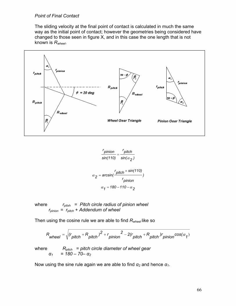
Point of Final Contact The sliding velocity at the final point of contact is calculated in much the same way as the initial point of contact; however the geometries being considered have changed to those seen in figure X, and in this case the one length that is not known is Rwheel.
)2sin(pitchr
sin(110)pinionr
α=
)pinionr
sin(110)pitchrarcsin(2
×=α
21101801 αα −−=
where rpitxh = Pitch circle radius of pinion wheel rpinion = rpitch + Addendum of wheel
Then using the cosine rule we are able to find Rwheel like so
)1cos(pinion)rpitchRpitch2(r2pinionr2)pitchRpitch(rwheelR α+−++=
where Rpitch = pitch circle diameter of wheel gear
α1 = 180 – 70– α2 Now using the sine rule again we are able to find α2 and hence α1.
66

)2sin(βpitchR
sin(70)wheelR
=
)wheelR
sin(70)pitchRarcsin(2β
×=
Thus we can find the linear velocity for the pinion and the gear at the initial point of contact
Vpinion.FIN = ωpinion x rpinion Vwheel.FIN = ωwheel x Rwheel
Where Θwheel and Θpinion are acting, tangential to
wheelVslidingV =
The table below shows tpoint of final contact.
Adendum (mm) r.pitch (mm) r.pinion (mm) R.pitch (mm) R.wheel (mm) Beta 1 Beta 2 Alpha 1 Alpha 2
67
represent the angle at which the initial sliding velocities their respective pitch circles.
2β90wheelθ −=
2α90
pinionθ −=
)pinionθwheelcos(θwheelVpinion2V2pinionV2 +−+
he calculated values from the above equations for the
Point of Final Contact 11.28888889 141.1111111 118.5333333 129.8222222
152.4 129.8222222 141.1111111 660.4 400.7555556 609.6
662.9843325 403.8498589 612.3255107 32.09520619 33.06710273 32.24276782 77.90479381 76.93289727 77.75723218 9.531393109 10.9094472 10.17237728 60.46860689 59.0905528 59.82762272
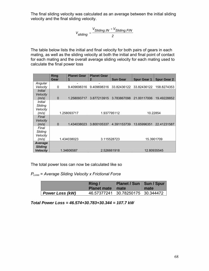
The final sliding velocity was calculated as an average between the initial sliding velocity and the final sliding velocity.
2NSliding.FIVSliding.INV
slidingV+
=
The table below lists the initial and final velocity for both pairs of gears in each mating, as well as the sliding velocity at both the initial and final point of contact for each mating and the overall average sliding velocity for each mating used to calculate the final power loss
Ring Gear
Planet Gear 1
Planet Gear 2 Sun Gear Spur Gear 1 Spur Gear 2
Angular Velocity 0
-9.409698316
-9.409698316 33.82436122 33.82436122 158.8274353
Initial Velocity
(m/s) 0 1.258093717 3.877213915 3.783867098 21.00117006 19.49228852Initial
Sliding Velocity
(m/s) 1.258093717 1.937795112 10.22854 Final
Velocity (m/s) 0 1.434038023 3.800105337 4.391153739 13.65996351 22.41231587Final
Sliding Velocity
(m/s) 1.434038023 3.115528723 15.3901709 Average Sliding Velocity 1.34606587 2.526661918 12.80935545
The total power loss can now be calculated like so
PLoss = Average Sliding Velocity x Frictional Force
Ring / Planet mate
Planet / Sun mate
Sun / Spur mate
Power Loss (kW) 46.57377241 30.78250175 30.344472 Total Power Loss = 46.574+30.783+30.344 = 107.7 kW
68
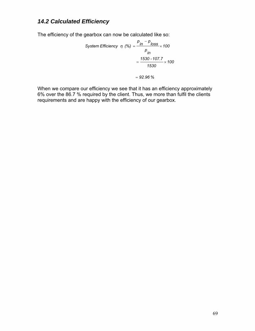
14.2 Calculated Efficiency The efficiency of the gearbox can now be calculated like so:
100in
ploss
pin
p (%) η Efficiency System ×
−=
1001530
107.7- 1530 ×=
%92.96 =
When we compare our efficiency we see that it has an efficiency approximately 6% over the 86.7 % required by the client. Thus, we more than fulfil the clients requirements and are happy with the efficiency of our gearbox.
69

15.0 Vibration Characteristics
15.1 Shaft Vibration Analysis Flow Chart
Calculate natural frequency for lateral
vibration
Import shaft parameters from
shaft design session
Compare the natural frequency of either one of the vibration mode with the angular velocity of the rotating shaft. Are they very similar in magnitude?
Yes No
No problem with current shaft design, done!
Calculate natural frequency for
torsional vibration
Vibration will be destructive to the system, so the shafts have to be redesign against vibration
70

There are two types of vibrations, namely lateral and torsional, could potentially become problems inside the gearbox due to the rotation of the shafts. For the reason that the applied radial loads on the shafts are all significantly larger than the weights of the shafts, the following vibration analysis1 is based on the assumption that the weights of the shafts are negligible.
15.2 Lateral Vibration Analysis Rotating shafts are nearly always part of a dynamics system of springs and masses. Because of imperfections in the manufacture and assembly of shafts and mounted components, and well as static deflections caused by the weights of these elements, the centre of mass does not coincide exactly with the centre of rotation of the system. Consequently when the shafts rotate with an angular velocity similar to the natural frequency of the system, the rotating centrifugal forces increase due to resonance, which will result a violent lateral bending-mode vibration. The nature frequencies for this mode of vibration are calculated below: In the case where there is only a single applied radial load on the rotating shaft, the natural frequency of the lateral vibration is
δϖ g
n =
For two radial loads, the natural frequency is
222
211
2211 )(δδδδϖ⋅+⋅
+=
FFFFg
n
where: g = gravity acceleration
F = applied radial load on the shaft δ = the resultant max deflection.
Shaft Number
Radial Load 1 (N)
Radial Load 2 (N)
Deflections 1 (m)
Deflections 2 (m)
Lateral Vibration ωn (rad/s)
0 337464 None 0.00010 None 313.209195 1 None None None None None
2,3,4 408727 143900 0.000070 0.00023 250.916127 5 78964 None 0.0000026 None 1942.44097 6. 78964 None 0.000025 None 626.418391
71
1 Reference : Demeter G. Fertis, “Mechanical and Structural vibrations” Jack A. Collins, “Mechanical Design of Machine Elements and Machines”

15.3 Torsional Vibration Analysis Torsional vibration occurs when the shafts experience fluctuating torques. The nature frequencies of this mode of vibration are calculated below: The natural frequency for the torsional vibration is:
JTk
n =ϖ
where Tk= torsional spring constant of the shaft = T/θ
J = polar moment of inertia = )2d( 5.0 4π
θ = torsional deflection = KGTL
K= J for a cylindrical shaft E = Young’s Modulus = 205 GPa v = passion ratio = 0.29
G=shear modulus = )1(2 ν+
E = 79.457364GPa
Shaft Number
Torque T (Nm)
Shaft Length L (m)
Shaft Diameter d (m)
polar moment of inertia J (m^4)
Torsional deflection θ (rad)
Torsional spring constant Tk (Nm/rad)
Torsional Vibration ωn (rad/s)
0 760815.5 4.7 0.741 0.029598706 0.001520444 500390460.4 130022.391 760815.5 0.4 0.359 0.001630714 0.0023487 323930506.9 445694.3
2,3,4 54197.66 0.777 0.15 4.9701E-05 0.010663566 5082507.931 319783.885 45233.67 1.2 0.129 2.71868E-05 0.025127552 1800162.219 257321.726 9633.096 0.325 0.075 3.10631E-06 0.012684406 759443.9736 494453.43
72

73
15.4 Vibration Analysis Summary Table
Shaft Number
Shaft Angular Velocity (rad/s)
Lateral Vibration ωn
(rad/s)
Torsional Vibration ωn
(rad/s)
0 2.011 313.209195 130022.39 1 2.011 None 445694.3
2,3,4 9.41 250.916127 319783.88 5 33.82436 1942.44097 257321.72 6. 158.8274 626.418391 494453.43
These two modes of vibrations will become seriously destructive when their natural frequencies are close to the angular velocity at which the shafts rotate due to effect of resonance. However, as the summary table above shows, the natural frequencies for lateral and torsional vibration are significantly bigger than the angular velocity at which the shaft rotates. Therefore, vibration will not be a concern for the gearbox.

16.0 Manufacture and Assembly
16.1 Gears Manufacturing of gears The gears in the gearbox are fabricated using various manufacturing processes to create the final product. Casting First a gear blank is cast with the required gear geometry. Gravity die casting or squeeze casting is commonly used. In squeeze casting, a premeasured quantity of molten metal is poured into a preheated die. The mould is then closed and pressure is applied until solidification is complete. Because of the precise metal metering, quiescent die filling, and high pressure, shrinkage and gas porosity are eliminated. The process has the advantage that it can produce fully shaped components, of precise dimensions, excellent surface finish and with metallurgical integrity equivalent to forgings, in one step. Machining of gear teeth There are several methods used to actually machine the teeth of the gears, each is discussed below: Milling In milling metal is removed by a rotating multiple-tooth cutter; each tooth removes a small amount of metal with each revolution of the spindle. Because both workpiece and cutter can be moved in more than one direction at the same time, surfaces having almost any orientation can be machined. The picture below shows the various forms of milling.
74

75
Hobbing The method is similar to the milling method, with the exception that the cutter and the gear blank rotate by complementing each other. As the hob is fed into the blank, the tooth form is created. Sharing This method is used to fabricate internal gears. In this process, the cutter usually reciprocates on the vertical spindle and it rotates while being fed in the gear blank. Usually, involute tooth form is created when this method is used. Induction Hardening Induction hardening allows the surface of steels to be hardened with minimum distortion or oxidation. A high frequency (up to 50kHz) electromagnetic field induces eddy-currents in the surface of the work-piece; these currents heat the surface into the austenitic phase-region, from which it is rapidly cooled from a gas or liquid jet, giving a martensitic surface layer. The depth of hardening depends on the frequency of the electromagnetic field. In flame hardening, heat is applied instead by means of one or more high-temperature gas burners, followed, as before, by rapid cooling. Both processes are versatile and can be applied to work pieces that cannot readily be furnace treated or case hardened in the normal way.

16.2 Shafts1
The shaft material used in this gearbox is AISI 4340 low alloy steel. The manufacturing process suggested to produce these shafts would be
1. Green Sand Casting Employ Green Sand Casting method to produce the dimensional requirements of the shafts. This type of casting is suitable for the selected material and purpose.
2. Turning
Where shafts have been specified steps, the process of Turning and high speed steel cutting tool shall be used to create the dimension and tolerance needed.
3. Grinding Where keyways have been specified, keyways can be created by process of grinding using a appropriate sized cylindrical grinding disc, while shaft is rigidly supported.
76
1 CES EDUPACK 2005

4. Boring The Main Input Shaft, incorporates a female spline and requires process of boring to create the initial hole.
5. Milling To create the splines on the Main and Intermediate shafts, the process of milling will be used to create the spline profile
6. Polishing As the shafts are undergoing high loading, surface finish given by Green Sand Casting and subsequent processing procedures would not be adequate. Poor surface finish introduces stress raising characteristics and unbalanced radial forces, hence polishing is appropriate for these shafts.
77

16.3 Assembly
1. Secure Ring Gear onto bottom housing section 2. Assemble Planetary Gear Sub-Assembly
Pre-assemble planetary gears into planetary shafts, via key-way. Connect bearings into planetary arms Connect and align planetary shafts into planetary arms
3. Insert and align Planetary Gear Sub-Assembly into the ring gear. 4. Slide Sun Gear into to Stage 1 Output shaft via key-way
5. Insert Stage 1 Output shaft (with Sun Gear) into position and temporarily
push sun gear past the planetary gears to allow for Stage 1 Spur Gear to be inserted on the other side.
6. Re-align Stage 1 Output shaft and insert bearing in between housing and
shaft
7. Install Oil spray system
8. Fix top half of gearbox housing onto bottom half
9. Assemble Stage 2 Output Shaft Sub-Assembly Insert bearing into ‘roof’ housing bearing support Insert Stage 2 Spur Gear onto Stage 2 output shaft Fix and align, shaft and gear assembly into bearings
10. Attach Stage 2 Output Shaft Sub-Assembly into the main housing
assembly.
11. Insert other Stage 2 Output Shaft bearing
12. Install shaft seals 78

79
Commissioning Procedure
1. Fill gearbox with gear oil up to recommended level 2. Grease all bearings 3. Run break-in procedure operating at low speeds for a period of time 4. Drain oil and refresh with new oil
17.0 Further Recommendations As outlined by the client, a full detailed design of the housing was not conducted. Calculations are required to determine the necessary strength in the support beams of the housing, and information is required from the client concerning the mounting location. As advised by Mr Weir the tooth stress calculations used a factor of safety of 1, to simplify the design process. Reconsideration of this assumption should be undertaken, and an appropriate factor of safety applied.
18.0 Conclusion This report detailed the design of gearbox for a Wind-Turbine. Our gearbox used 2 stages, the first stage using a compound epicylic planetary stage with a gear ratio of 1:16.82, followed by a parallel shaft spur gear stage with a gear ratio of 1:4.69. This ensured that the input and output shafts were not coaxially aligned to facilitate the installation of the rotor blade pitch controller. The client requested that the following restraints were met:
Client Requirements Team 20 Gear
Box Design Requirement Surpassed
Height 2.2m 2.14m 0.06m Width 3.3 2.08m 1.22m Length 1.7 1.62 0.08
Efficiency 86.7% 92.96% 6.26% Transmit Power
with Gear Ratio of 79.0625
±1% Error 78.99
0.08% Error The use of a compound epicylic gear stage enabled us to minimize the weight and therefore the cost of materials used to approximately 5 tonnes (not including the housing). The gearbox design has been taken to the stage where all important decisions have been made.

80
19.0 References Samuel, A. Weir, J. (2000) Introduction to Engineering Design, Modeling, Synthesis and Problem Solving Strategies, Butterworth Heinemann Shigley, J.F. (2004) Mechanical Engineering Design McGraw Hill British Standards Gear Design Standard BS436 (1940) Australian Standards – Design of Rotating Shafts AS1403 (2004) www.skf.com Demeter G. Fertis, “Mechanical and Structural vibrations”, Jack A. Collins, “Mechanical Design of Machine Elements and Machines” http://www.co-design.co.uk/dpg/grs/grs15.htm www.windpower.org/en/tour/wtrb/powtrain.htm www.manufacturingtalk.com/news/bre/bre102.html www.nrel.gov/wind/pdfs/dg04_000203.pdf www.howstuffworks.com/gear.htm www.efunda.com/designstandards/gears/gears_introduction.cfm www.drgears.com www.ecs.umass.edu/mie/labs/mda/dlib/machine/gear/spur_fund.html www.roymech.co.uk/Useful_Tables/Drive/Gears.html www.mech.uwa.edu.au/DANotes/gears/epicyclic/epicyclic.html www.roymech.co.uk/Useful_Tables/Drive/Hellical_Gears.html

81

82
APPENDIX A – Gears Torque Calculations Power In 1530 kW Torque In 760.95957 kNm First Stage Number of Planets 3 GearsRadius of R 0.6604 m Radius of P1 0.1411111 m Radius of P2 0.4007556 m Radius of S 0.1185333 m Torque.Arm 760.95957 kNm Torque.P1 50.977628 kNm Torque.P2 -50.97763 kNm Torque. Sun 45.23367 kNm F.Ring 361.25878 kN F.P1 361.25878 kN F.P2 127.2038 kN F.Sun 127.2038 kN Second Stage Radius of S1 0.6096 m Radius of S2 0.1298222 m Torque S1 45.23367 kNm Force.S1 74.202215 kN Force.S2 74.202215 kN Torque.S2 9.6330964 kNm
Hertzian and Bending Stresses Hertzian: Minimum Face Width Ring and Planet 1 Gears 242.588 mm Planet 2 and Sun Gears 168.8312 mm Stage 2 Spur Gear 1 & 2 Set 124.71658 mm Bending: Minimum Face Width Ring and Planet 1 Gears 247.89187 mm Planet 2 and Sun Gears 112.15395 mm Stage 2 Spur Gear 1 & 2 Set 89.623822 mm Overall: Minimum Face Width Ring and Planet 1 Gears 247.89187 mm Planet 2 and Sun Gears 168.8312 mm Stage 2 Spur Gear 1 & 2 Set 124.71658 mm Material Properties Density 7900 kg/m3

83
Spatial Constraints Overall Gear Box Width 1840.0889 mm Overall Gear Box Height 1840.0889 mm Overall Gear Box Length 595.58361 mm Ring Gear Mass 1357.3258 kg Planet 1 Gear Mass 122.50721 kg Planet 2 Gear Mass 672.95927 kg Sun Gear Mass 58.872255 kg Stage 2 Spur Gear 1 1150.2469 kg Stage 2 Spur Gear 2 52.167404 kg Total Mass 5005.0119 kg Location of input shaft Centre of Nacelle
Location of output shaft 0.739 m vertical displacement
Stage 1 Planet 1 Planet 2 Sun Input
Arm Ring Gear Rotational Linear Rotational Linear Rotational Linear Total
Gear Ratio
N/A 117 25 71 21 2.010619 0 -9.4097 2.010619 -9.4097 2.010619 31.81374 2.010619 33.82436 16.822857
Gear 1 Gear 2 Gear Ratio
Total Gear Ratio
108 23 33.82436 158.8274 4.6956522 78.994286
Mating A Mating B Mating C
Ring Gear Planetary
Gear Planetary
Gear Sun GearSpur Gear
1 Spuir Gear 2
Number of Teeth
117 25 71
21
108 23 Zone Factor (Z) 3.679 3.679 2.200 2.200 2.450 2.450 Speed Factor
(Xc) 0.650 0.650 0.550 0.550 0.390 0.390 Sc 8000.000 8000.000 8000.000 8000.000 8000.000 8000.000
Ft (lbs) 81213.865 81213.865 28596.431 28596.431 16681.252 16681.252 Factor of Safety 1.000 1.000 1.000 1.000 1.000 1.000 Pitch Factor (K) 2.250 2.250 2.250 2.250 2.250 2.250
D (in) 52.000 11.111 31.556 9.333 48.000 10.222 Diameter (cm) 132.080 28.222 80.151 23.707 121.920 25.964
Ouside Diameter 172.080 b (in) 9.551 9.551 6.647 6.647 4.910 4.910
b (mm) 242.588 242.588 168.831 168.831 124.717 124.717

Mating A Mating B Mating C Ring Gear Planetary Gear Planetary Gear Sun Gear Spur Gear 1 Spuir Gear 2
No. of Teeth 117 25 71 21 108 23 Strength Factor
(Y) 0.757 0.757 0.718 0.718 0.741 0.741 Speed Factor
(Xb) 0.500 0.500 0.410 0.410 0.290 0.290 Sb 49500.000 49500.000 49500.000 49500.000 49500.000 49500.000
Ft (lbs) 81213.865 81213.865 28596.431 28596.431 16681.252 16681.252 Factor of Safety 1.000 1.000 1.000 1.000 1.000 1.000
Diametral P 2.250 2.250 2.250 2.250 2.250 2.250 D (in) 52.000 11.111 31.556 9.333 48.000 10.222
Diameter (cm) 132.080 28.222 80.151 23.707 121.920 25.964 Ouside Diameter 172.080
b (in) 9.760 9.760 4.416 4.416 3.528 3.528 b (mm) 247.892 247.892 112.154 112.154 89.624 89.624
Ring Gear Planet Gear 1
Planet Gear 2 Sun Gear Spur Gear 1 Spur Gear 2
Angular Velocity 0 -
9.409698316-
9.409698316 33.82436122 33.82436122 158.8274353Initial Velocity (m/s) 0 1.258093717 3.877213915 3.783867098 21.00117006 19.49228852Initial Sliding Velocity (m/s) 1.258093717 1.937795112 10.22854 Final Velocity (m/s) 0 1.434038023 3.800105337 4.391153739 13.65996351 22.41231587Final Sliding Velocity (m/s) 1.434038023 3.115528723 15.3901709 Average Sliding Velocity 1.34606587 2.526661918 12.80935545
84

85
Point of Initial Contact Adendum (mm) 11.28888889 r.pitch (mm) 141.1111111 118.5333333 129.8222222r.pinion (mm) 133.7018121 111.8681022 122.7262058R.pitch (mm) 660.4 400.7555556 609.6R.wheel (mm) 671.6888889 412.0444444 620.8888889Beta 1 2.497015125 3.943285888 2.689721991Beta 2 67.50298488 66.05671411 67.31027801Alpha 1 27.35716035 25.32728581 26.26618279Alpha 2 82.64283965 84.67271419 83.73381721 Point of Final Contact Adendum (mm) 11.28888889 r.pitch (mm) 141.1111111 118.5333333 129.8222222r.pinion (mm) 152.4 129.8222222 141.1111111R.pitch (mm) 660.4 400.7555556 609.6R.wheel (mm) 662.9843325 403.8498589 612.3255107Beta 1 32.09520619 33.06710273 32.24276782Beta 2 77.90479381 76.93289727 77.75723218Alpha 1 9.531393109 10.9094472 10.17237728Alpha 2 60.46860689 59.0905528 59.82762272
Ring /
Planet mate Planet / Sun mate
Sun / Spur mate
Tangential Force (kN) 361.25878 127.2038 74.202215Pressure Angle 20 20 20Normal Force (kN) 384.4435638 135.3674565 78.96434787Friction Coefficient 0.03 0.03 0.03Friction Force (kN) 11.53330691 4.061023695 2.368930436Total Force (per stage) (kN) 34.59992074 12.18307109 2.368930436 Power Loss (kW) 46.57377241 30.78250175 30.344472Total Loss (kW) 107.7007462 Power Input (kW) 1530 Efficiency (%) 92.96073554

APPENDIX B- Shafts Main Input Shaft
86
P
D1 D2
S
B
FBD
Input Torque
850 850 1500 1500
% MATLAB code to compute minimum shaft diameter of Main Input Shaft, using % DEFP as stated in AS1403 % Calculate Mass of Shaft d= 741; density=7850/1000000000; % Reaction Forces P=34400*9.81; D1= ((pi*d.^2)/4)*1700*density*9.81; D2=((pi*d.^2)/4)*density*3000*9.81; S=(R*1700+D1*850-D2*1500)/3000; B= R+D1+D2+S; % Max Moment M= R*1700+D1*(1700-850); % DEFP Fd= 1.3*1.5*1.4*1*1.1*1.1*1.1*1.2; Se=711; T=(1530*1000*1000)/(1.92*2*pi/60); Q=(10*Fd)/Se; d=( Q* ( M.^2+ (3*T^2/4) ).^(1/2) ).^(1/3) clear all;
• Calculated minimum diameter is 741mm. • Iterative processing of code suggests weight of shaft negligible <1mm.

FBD
87
P R1 R2
3m1.7m
-
+
-
-337464N
573689Nm
% MATLAB code -Deflection Solver (Main Input Shaft) x=0:1:4700; P = 34400*9.81; R2= (R1*1700)/3000; R3=R1+R2; C1= (R2*3000^3)/18000; y= 2.22; E=205*1000; II=(pi*741^4)/64; I= ( -(1/6)*R2*x.^3 + (1/6)*R3*(x-3000).^3 + C1*x )./ (E*y); Y= ( -(1/6)*R2*x.^3 + (1/6)*R3*(x-3000).^3 + C1*x )./ (E*II) D=((I.*64)./pi).^(1/4); plot(x,D); title ('Minimum Diameters of Output Shaft Stage 1 Shaft - Deflection'); xlabel('x (mm) (Length of Shaft)'); ylabel('Minimum shaft diameter (mm)'); figure; plot(x,Y); title ('Deflection Curve'); xlabel('x (mm) (Length of Shaft)'); clear all;

88

Intermediate Input Shaft FBD
0 N
• No Net Bending due to arrangement of planetary shaft plate. Tangential and
Radial forces cancel.
Fs Fs
Ft
Ft
Ft
Fs
89

90
Minimum Shaft Diameter Calculation Power In 1530 kW Intermediate Input Shaft Angular Velocity 2.011 rad/s Torque 760815.5 N.m Initial Trial Diameter 300 mm K factors 1 Pq (axial) 0 No Net Bending DEFP min Shaft Diameter Trial Diameter 359 Fs 2 Fr 711 Mpa Ks 1.8
K 2.2Keyway H7-s6
Mq 0 Pq 0 Tq 760815.5 D^3 45964450 D 358.2125 mm 35.82125 cm Error -0.21985
Deflection
• None, as there’s no net bending.

Output Shaft Stage 1 FBD X-Y PLANE
91
FBD Z-X PLANE
113mm
-
+
+
4174Nm
36936N 37266N594mm
74202N
36936N
113mm
-
+
+
1519Nm
13385N 13622N594mm
27007N
13444N
-13564N
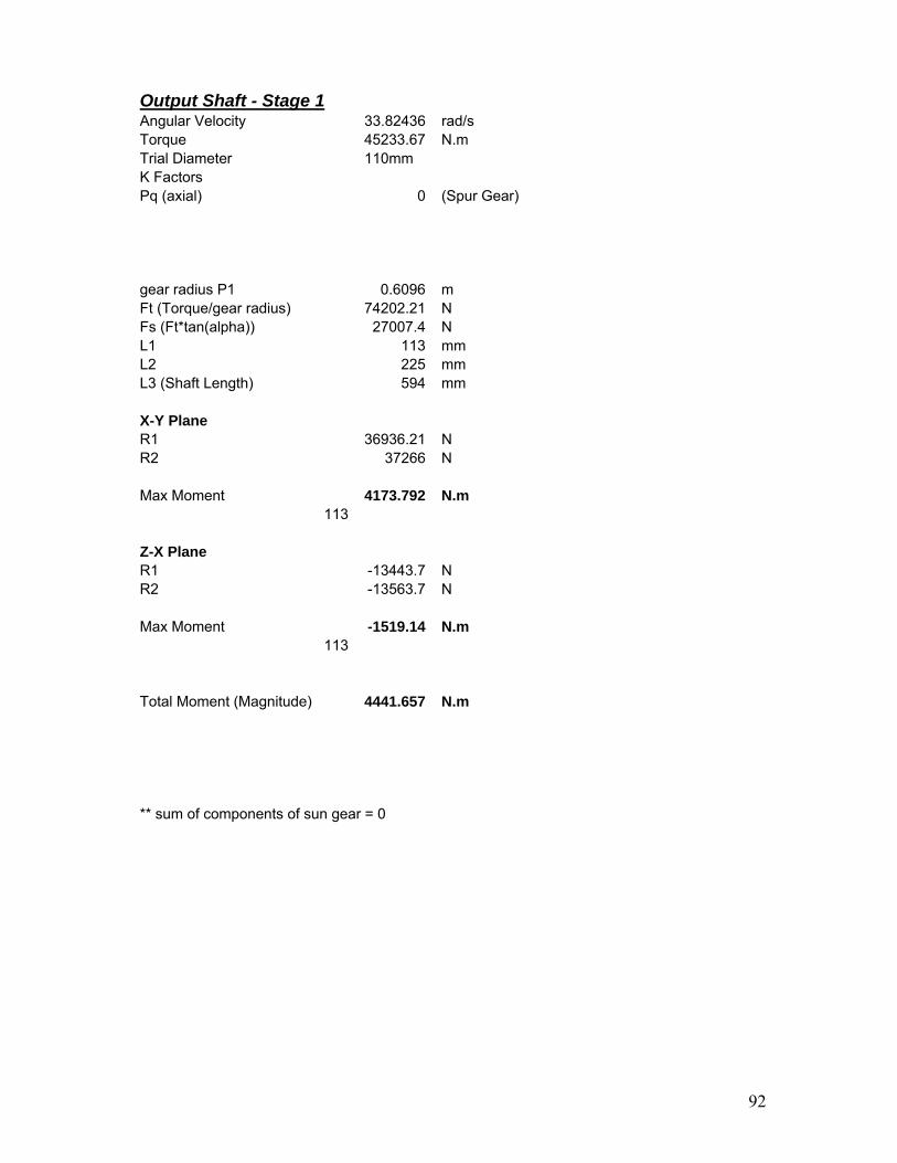
92
Output Shaft - Stage 1 Angular Velocity 33.82436 rad/s Torque 45233.67 N.m Trial Diameter 110mm K Factors Pq (axial) 0 (Spur Gear)
gear radius P1 0.6096 m Ft (Torque/gear radius) 74202.21 N Fs (Ft*tan(alpha)) 27007.4 N L1 113 mm L2 225 mm L3 (Shaft Length) 594 mm X-Y Plane R1 36936.21 N R2 37266 N Max Moment 4173.792 N.m
113 Z-X Plane R1 -13443.7 N R2 -13563.7 N Max Moment -1519.14 N.m
113 Total Moment (Magnitude) 4441.657 N.m ** sum of components of sun gear = 0

93
DEFP min Shaft Diameter Trial Diameter 164 Fs 2 Fr 711 Mpa Ks 1.7
K 4Keyway H7-k6 (greater of 2)
Mq 4441.657 Pq 0 Tq 45233.67 D^3 4380692 D 163.6242 mm 16.36242 cm Error -0.22967
STEP FACTORS FOR BEARINGS AND SUN GEAR Sun Gear DEFP min Shaft Diameter Trial Diameter 163 Fs 2 Fr 711 Mpa Ks 1.7 K 4 Keyway H7-k6 (greater of 2) Mq 0 Pq 0 Tq 45233.67 D^3 4297516 D 162.582 mm 16.2582 cm Error -0.2571

94
Bearing X-Y Plane R1 36936.21 N R2 37266 N Max Moment at bearing 923.4053 N.m
25 Z-X Plane R1 -13443.7 N R2 -13563.7 N Max Moment at bearing -336.092 N.m
25 Total Moment (Magnitude) 982.6674 N.m ** sum of components of sun gear = 0 DEFP min Shaft Diameter Trial Diameter 129 Fs 2 Fr 711 Mpa Ks 1.7 K 1.7 Bearing K8-h6 + notch (neg.) Mq 982.6674 Pq 0 Tq 45233.67 D^3 2144736 D 128.9609 mm 12.89609 cm Error -0.03034

DEFLECTION % MATLAB code to calculate deflection and min diameter due to deflection for Output Shaft Stage 1 L2 = 225; L1 = 113; E = 205*1000; defa=2.22; II=((pi*164^4))/64; x=0:1:L2; Fmax1 = (74202.21^2+27007.4^2)^(1/2); R2 = (Fmax1*L1)/L2; R1 = Fmax1-R2; y1 = ((R1.*x.^3)./6) - (Fmax1/6.)*(x-L1).^3 + ((1/L2).* (((-R1*L2.^3)./6) + (Fmax1/6)*(L2-L1).^3).*x); YY1=y1./(E*II); I1 = y1./(E*defa); d1 = ((I1.*64)/pi).^(1/4); plot(x,d1); title ('Minimum Diameters of Output Shaft Stage 1 Shaft - Deflection'); xlabel('x (mm) (Length of Shaft)'); ylabel('Minimum shaft diameter (mm)'); hold on; figure; plot(x,YY1); title ('Deflection Curve'); xlabel('x (mm) (Length of Shaft)'); clear all;
95
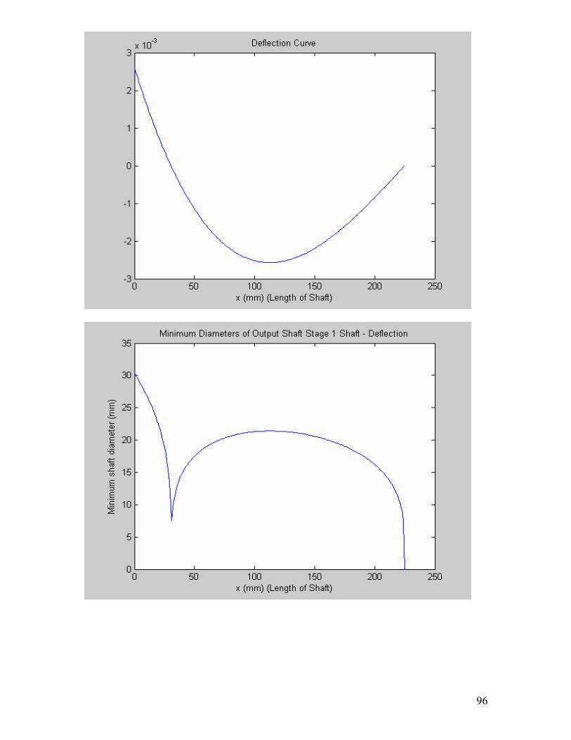
96

Output Shaft - Stage 1
FBD Z-X PLANE
115mm
-
+
+
4595Nm
40663N 33539N 225mm
74202N
40663N
-33539N
115mm
-
+
+
1672Nm
14800N 12207N225mm
27007N
14800N
-12207N
FBD X-Y PLANE
97

98
Output Shaft - Stage 2 Angular Velocity 158.8274 rad/s Torque 9633.096 N.m Trial Diameter 28 mm K Factors
Pq (axial) 0(Spur Gear)
gear radius P1 0.129822 m Ft (Torque/gear radius) 74202.21 N Fs (Ft*tan(alpha)) 27007.4 N L1 113 mm L2 250 mm L3 (Shaft Length) 350 mm X-Y Plane R1 14800.05 N R2 12207.34 N Max Moment 1672.406 N.m
113 Z-X Plane R1 40662.81 N R2 33539.4 N Max Moment 4594.898 N.m
113 Total Moment 4889.788 N.m DEFP min Shaft Diameter Trial Diameter 100 Fs 2 Fr 711 Mpa Ks 1.25 K 4 Mq 4889.788 Pq 0 Tq 9633.096 D^3 984178.1 D 99.4698 mm 9.94698 cm Error -0.53303

99
STEP FACTORS FOR BEARINGS Bearing X-Y Plane R1 14800.05385 N R2 12207.34368 N Max Moment 370.0013462 N.m
25 Z-X Plane R1 40662.81375 N R2 33539.40113 N Max Moment 1016.570344 N.m
25 Total Moment 1081.811564 N.m DEFP min Shaft Diameter Trial Diameter 72 Fs 2 Fr 711 Mpa Ks 1.25 K 1.7 Bearing K7-h6 + Notch (neg) Mq 1081.811564 Pq 0 Tq 9633.096429 D^3 372329.7767 D 71.94090938 mm 7.194090938 cm Error -0.082137717
• Specify diameter of bearing step to be 75mm, due to bearing selection available.

DEFLECTION %MATLAB code to calculate deflection and min diameter due to %deflection for Output Shaft Stage 1 L2 = 250; L1 = 113; E = 205*1000; defa=2.22; II=((pi*100^4))/64; x=0:1:L2; Fmax1 = (74202.21^2+27007.4^2)^(1/2); R2 = (Fmax1*L1)/L2; R1 = Fmax1-R2; y1 = ((R1.*x.^3)./6) - (Fmax1/6.)*(x-L1).^3 + ((1/L2).* (((-R1*L2.^3)./6) + (Fmax1/6)*(L2-L1).^3).*x); YY1=y1./(E*II); I1 = y1./(E*defa); d1 = ((I1.*64)/pi).^(1/4); plot(x,d1); title ('Minimum Diameters of Output Shaft Stage 1 Shaft - Deflection'); xlabel('x (mm) (Length of Shaft)'); ylabel('Minimum shaft diameter (mm)'); hold on; figure; plot(x,YY1); title ('Deflection Curve'); xlabel('x (mm) (Length of Shaft)'); clear all;
100

101

APPENDIX C- Bearings
102
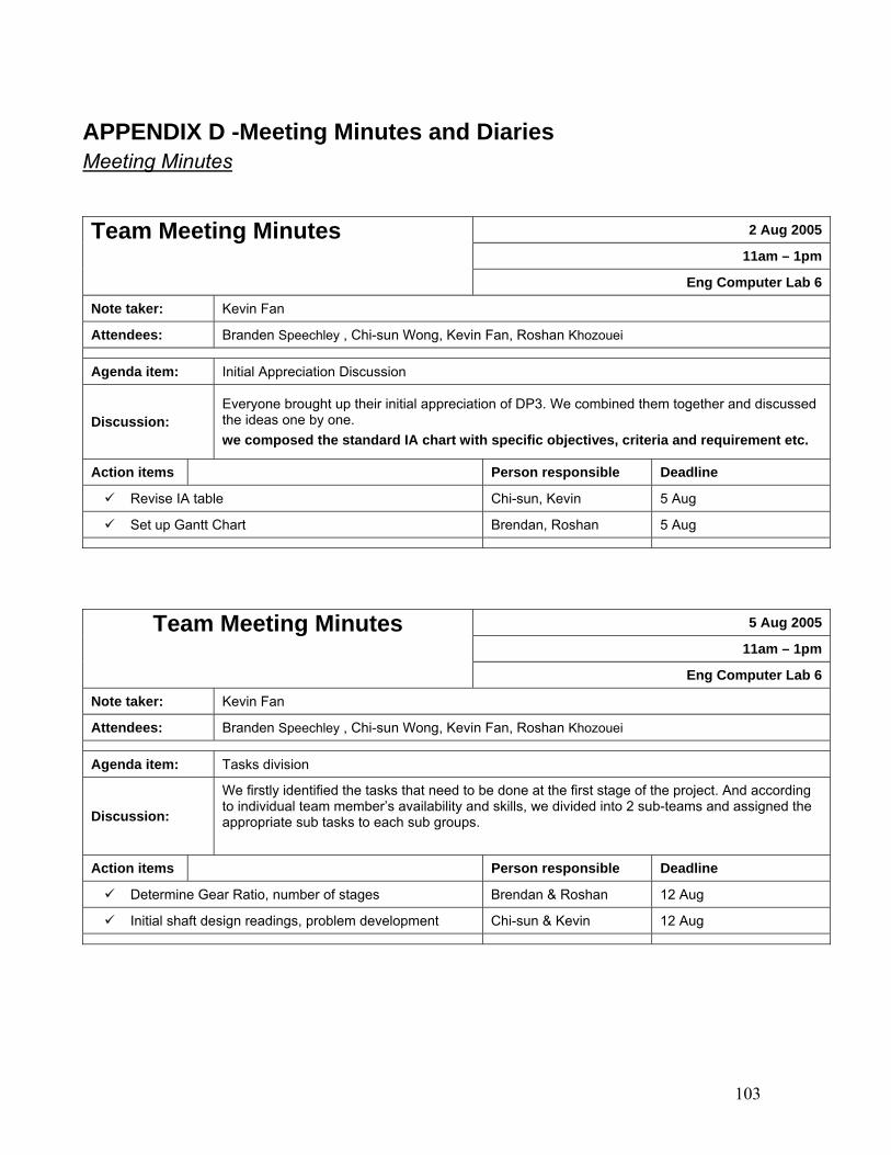
APPENDIX D -Meeting Minutes and Diaries Meeting Minutes
2 Aug 2005
11am – 1pmTeam Meeting Minutes
Eng Computer Lab 6
Note taker: Kevin Fan
Attendees: Branden Speechley , Chi-sun Wong, Kevin Fan, Roshan Khozouei
Agenda item: Initial Appreciation Discussion
Discussion: Everyone brought up their initial appreciation of DP3. We combined them together and discussed the ideas one by one. we composed the standard IA chart with specific objectives, criteria and requirement etc.
Action items Person responsible Deadline
Revise IA table Chi-sun, Kevin 5 Aug
Set up Gantt Chart Brendan, Roshan 5 Aug
5 Aug 2005
11am – 1pmTeam Meeting Minutes
Eng Computer Lab 6
Note taker: Kevin Fan
Attendees: Branden Speechley , Chi-sun Wong, Kevin Fan, Roshan Khozouei
Agenda item: Tasks division
Discussion:
We firstly identified the tasks that need to be done at the first stage of the project. And according to individual team member’s availability and skills, we divided into 2 sub-teams and assigned the appropriate sub tasks to each sub groups.
Action items Person responsible Deadline
Determine Gear Ratio, number of stages Brendan & Roshan 12 Aug
Initial shaft design readings, problem development Chi-sun & Kevin 12 Aug
103

11 Aug 2005
6pm – 8pmTeam Meeting Minutes Eng Library
Note taker: Branden Speechley
Attendees: Branden Speechley , Chi-sun Wong, Kevin Fan, Roshan Khozouei
Agenda item: Preliminary gearbox shaft design
Discussion:
We agreed to set up a fixed meeting time, which is 6pm every Thursday and all team members should attend. Sub-teams should arrange own time for additional meeting to work on assigned tasks. Roshan and Brendan showed research finding on gear type options, including: Spur gear, internal spur, helical and double helical thrust etc. Kevin and Chi-sun presented the following:
- Forces acting on Main input shaft - DEFP method to predict min shaft diagram, of Main input shaft - Shaft self weight found to be negligible
Gear design involved more work than expected, need to speed up the progress
Action items Person responsible Deadline
Decide gear ratio and other gear parameters Brendan & Roshan 18 Aug 2005
Draw shaft design flowchart & SFD and BMD Kevin 18 Aug 2005
Await gear parameters to calculate force acting on shaft Chi-sun 18 Aug 2005
104

18 Aug 2005
6pm – 9pmTeam Meeting Minutes
Eng Computer Lab 6
Note taker: Branden Speechley
Attendees: Branden Speechley , Chi-sun Wong, Kevin Fan, Roshan Khozouei
Agenda item: gearbox & shaft design progress meeting
Discussion:
Roshan & Brendan presented a progress report on gear design • Decided to use a Planetary Epicyclic gear box design • Decided the number of stage and basic layout • Started spreadsheet with all calculations and information required for gear
design including: -Dimensions for each gear (number of teeth, pitch radius) -Torques transferred at each stage -Forces generated between each pair of mating gears -Angular and linear velocity of each gear • Material selected is AISI 4340, low alloy steel.
Chi-sun and Kevin presented - Investigate manufacturing aspects of shafts, such as assembly and
manufacturing - Present SFD & BMD of the shafts with variable forces
Action items Person responsible Deadline
Supply Chi-sun the gear parameters Roshan asap
Write MATLAB code for deflection Chi-sun 24 Aug 2005
Start investigations into bearing selection Kevin TBA
Get farmiliar with Solidwork Brendan TBA
105

24 Aug 2005
6pm – 9pmTeam Meeting Minutes
Eng Computer Lab 6
Note taker: Chi-sun Wong
Attendees: Branden Speechley , Chi-sun Wong, Kevin Fan, Roshan Khozouei
Agenda item: Gear and shaft design summery meeting
Discussion:
Gear and shaft design have basically done roughly. We then prepared more proper documents for Progress report session tomorrow Brendan got a basic 3D model of our gears & shafts drawn on Solidwork. Shaft material changed to be AISI 4340, which is the material chosen for gear. The main reason of the decision is concern of wearing between the gears and shafts. Chi-sun done MATLAB code, which calculated all the shaft diameters
Action items Person responsible Deadline
Working on heat generation and efficiency of gear box Roshan TBA
specify the exact positioning of gears, shafts and b i
Chi-sun & Brendan 1 Sep 2005
finish bearing selection Kevin 1 Sep 2005
1 Sep 2005
6pm – 9pmTeam Meeting Minutes
Eng library
Note taker: Chi-sun Wong
Attendees: Branden Speechley , Chi-sun Wong, Kevin Fan, Roshan Khozouei
Agenda item: heat generation and efficiency, bearing selection
Discussion:
Kevin discussed the selected bearing specification and the bearing positioning, so Brendan could go on drawing them in Solidwork. Roshan’s going well with the heat generation and efficiency calculation, expected to be finished soon. Brendan started writing the proper gear design report Chi Sun Start writing the proper shaft design report We together revised the Gantt Chart in order to meet the report submission deadline.
Action items Person responsible Deadline
finish heat generation & efficiency & start design sealing Roshan 7 Sep 2005
start and finish vibration analysis Kevin 7 Sep 2005
finish writing the gear report & drawing the 3D gear d l
Brendan 7 Sep 2005
finish writing the shaft report & start lubrication design Chi Sun 7 Sep 2005
106

7 Sep 2005
5pm – 11pmTeam Meeting Minutes
Eng Computer Lab 5
Note taker: Roshan Khozouei
Attendees: Branden Speechley , Chi-sun Wong, Kevin Fan, Roshan Khozouei
Agenda item: Meeting for finalize everything
Discussion:
We started the discussion by finding out what tasks left, which include: sealing design, 3D gear modeling in solidwork and lubrication and housing. We spent the following 5 hours to complete as much tasks as possible.
Action items Person responsible Deadline
turn up for tomorrow for last meeting All team member 8 Sep 2005
8 Sep 2005
1pm – 9pmTeam Meeting Minutes
Eng Computer Lab 6
Note taker: Roshan Khozouei
Attendees: Branden Speechley , Chi-sun Wong, Kevin Fan,
Agenda item: Get ready for submission
Discussion:
We stayed in computer lab all to finish off the design project., which including
• compile all design sessions
• proof reading and edit all the writing
• export animation from our gearbox design model from solidwork
• printing and binding of the report
107

Design Diaries - Brendan Speechley’s Design Diary Date: Thursday July 28th Total Time: 2 hours
• Begin research into gear design and current wind turbine gear designs. • Collect information to create a database which can be referenced back to in the
future when questions arise.
Date: Monday August 1st Total Time: 2 hours
• Gathering Information on Wind Turbines and the current gearbox types employed. • Visited the following sites:
- www.windpower.org/en/tour/wtrb/powtrain.htm - www.manufacturingtalk.com/news/bre/bre102.html - www.nrel.gov/wind/pdfs/dg04_000203.pdf - www.howstuffworks.com/gear.htm - www.efunda.com/designstandards/gears/gears_introduction.cfm - www.drgears.com
Date: Tuesday August 2nd Total Time: 3 hours
• Continue research into gearbox design in modern wind turbines • Begin working on initial appreciation with group members • Brainstorming ideas for wind turbine design • Drafting criteria and objectives list • Writing up Gantt chart with Roshan
Date: Wednesday August 3rd Total Time: 2 hours
• Finalise Initial Appreciation in preparation for tomorrows assessment • Fix up Criteria and objectives list • Added points to additional consideration • Produced a list of questions to ask the coordinator.
108

Date: Monday August 8th Total Time: 1.5hour
• In conjunction with Roshan investigating suitable gear types • Began working on suitable gear train designs
- Simple train, - Compound train - Epicyclic trains - Coupled Epicyclic trains
• Visited the following sites : - www.ecs.umass.edu/mie/labs/mda/dlib/machine/gear/spur_fund.html - www.roymech.co.uk/Useful_Tables/Drive/Gears.html - www.mech.uwa.edu.au/DANotes/gears/epicyclic/epicyclic.html - www.roymech.co.uk/Useful_Tables/Drive/Hellical_Gears.html
Date: Thursday August 11th Total Time: 2 hours
• It has been decided to use spur gears for gear box design, • Decide to use a Planetary Epicyclic gear box design
- The advantages of a Planetary Epicyclic gear box are its small compact size, and the ability to have a high reduction ratio with only one planetary stage.
- This is considerable advantage as we are constrained by size, and we also wish to minimise the amount of material use and weight in order to save money for the client.
• Begin investigation into types of planetary gears. • Possible designs to get the required gear ratio • Consider a moving ring gear with static planets or a static ring gear with moving
planets. - It was decided to use a static ring gear and moving planets as then the forces
and torque would be shared among the three planets - This design also allows for a more simple shaft design and simpler housing
attachments. • Number of planets: - It was decided that three planets each offset at 120 degrees would be used so to create a force equilibrium. • Additional gear change on planets - The three internal planets will have a larger gear offset so as to allow for an additional stage within our planetary gear box.
109

Date: Tuesday August 16th Total Time: 4 hours
• Begin defining gear ratio • Number of teeth • Number of stages - Decided on two stages, - Stage 1: Epicyclic Planetary involving - 1 Ring Gear - 3 Small planets - 3 Offset large planets - 1 Sun gear - Stage 2: Simple Spur - 1 large spur gear offset from sun gear - 1 Small final spur gear, It has been decided that the last gear is required to offset the output in the required direction. • Number of teeth on each gear. • Gear Pitch radius for
- Ring Gear - Planetary gear 1 - Planetary gear 2 - Sun Gear - Simple Spur gear 1 - Simple Spur gear 2
Date: Thursday August 18th Total Time: 3 hours
• Working in conjunction with Roshan to optimise the gear box using the spreadsheet to update details, and trying different materials for gears..
• To minimise weight I decided to remove sections of the gear disk. It was found that by doing this I was able to decrease the weight of the gearbox by approximately 25%.
• Insert additional geometric dimensions into the spreadsheet that will be required when building the gear box
110

Date: Monday 22nd August Total Time: 2 hours
• Approximate gear ratios were defined and input into the spreadsheet, after optimisation and alteration of the diametral pitch I decided upon the following Gear Ratios - Ring Gear
- Number of teeth: 177 - Pitch Radius: 660.4 mm - Angular Velocity: 0 - Linear Velocity : N/A - Planetary gear 1 - Number of planets : 3 - Number of teeth on each gear : 25 - Pitch Radius: 141.11 mm - Angular Velocity: -9.4097 rad/sec - Linear Velocity: 2.010619 m/s - Planetary Gear 2 - Number of gears : 3 - Number of teeth on each gear: 71 - Pitch Radius: 400.75556 mm - Angular Velocity: -9.4097 rad/sec - Linear Velocity: 2.010619 m/s - Sun Gear - Number of teeth: 21 - Pitch Radius: 128.53333 mm - Angular Velocity 31.8137 rad/sec - Linear Velocity: 2.010619 m/s - Spur Gear 1 - Number of teeth: 108 - Pitch Radius: 609.6 mm - Angular Velocity: 33.82436 rad/sec - Linear Velocity N/A - Spur Gear 2 - Number of teeth: 23 - Pitch Radius: 129.8222mm - Angular Velocity: 158.8274 rad/sec - Linear Velocity: N/A Gear Ratio: Stage One (Epicyclic Planetary): 16.822857 Stage Two (Simple Spur): 4.6956522 Total Gear Ratio 78.994 Required Gear Ratio 79.0625 Error >1 %
• Began drawing up all individual parts in solid works according to the now defined geometry. Created - Ring Gear - Planets
111

Date: Wednesday August 24th Total Time: 1 hour
• Begin preparation for progress report. • Format information and tables suitable for presentation • Began working on developing involute tooth profile to cut out of parts.
Date: Friday September 2nd Total Time: 2 hours
• Start to write up gear design report • Continue work on solid works design
Date: Wed September 7th Total Time: 6 hours
• Chi-sun had minor changed on shaft diameters, cost me quite lots of time to redraw everything connected to the shaft in Solidwork.
• I discussed with Kevin on the bearing supports. We came up with an ‘arm support’ idea, on which the bearing can be mounted on.
Date: Friday September 2nd Total Time: 8 hours
• The housing of the gearbox took me more than 4 hours to draw in solid. • The gearbox model is then export to video file for making it more easily
accessible.
112

- Chi Sun Wong’s Design Diary Date: 2nd July 2005 Total Time: 1 hours
• Initial readings into design problem. Read project handout and background readings into wind turbine gearboxes at various websites
• Considered Initial appreciation
Date: 1st August 2005 Total Time: 2 hours
• Start Initial Appreciation • Defined objectives and respective criteria such as Safety, Performance, Durability,
Size/weight, Manufacturing, maintenance, Transportation, Environment • Rated objectives • Thought about information required • Problems foreseen • Writing up initial appreciation report
Date: 2nd August 2005 Total Time: 3 hours
• Attended group meeting • Discuss individual effort on initial appreciation • Preparation on initial appreciation submission •
Date: 5th Aug 2005 Total Time: 3 hours
• Attended group meeting • Was assigned the task of Shaft design with Kevin • Read through Introduction to engineering design on shafts • Identified failure modes to be yielding, fatigue and deflection • Chose DEFP to be the main failure predictor which takes into account bending
and torsion and the identified failure modes except deflection. More aggressive than MSFP
• Considered design of main input shaft. Involved developing control area, force analysis, which is mainly contributed by the rotor mass
• Considered effect of self weight of shaft
113

Date: 11Aug 2005 Total Time: 2 hours
• Attended group meeting • Developed MATLAB code incorporating DEFP from Introduction to Engineering
Design book. • Formalisation of FBD, SFD and BMD of main input shaft • Initial diameters found, but material not finalised • Self weight of shaft found to be insignificant as difference is in the order of 10^-2
mm and not practical in real life manufacturing capabilities • Obtained initial layout of gearbox and shafts needed
Date: 16 Aug 2005 Total Time: 3 hours
• Met up with Kevin to continue on shaft work • Read on AS1403 year 2004. The equation is updated hence we will used the
updated version • Updated MATLAB code for AS1403 • Considered forces acting on shafts due to gears – tangential, radial, axial • Initial drawings of FBD, SFD and BMD based on initial information • Further appreciation of DEFP failure predictor and assumptions required to carry
out design • Initial construction of shaft design flow diagram
Date: 18 Aug 2005 Total Time: 3 hours
• Attended group meeting • Researched on manufacturing aspects of shafts • Started on shaft deflection analysis – require double integration method and
superposition • Had trouble defining allowable deflection limits on shafts • Analysed new gear data and considered implication on shafts. Updated FBD and
diagrams accordingly. • Forces involved are tangential and radial since gears are specified as Spur gears
Date: 23 Aug 2005 Total Time: 2 hours
• Writing of deflections expressions and inputting into MATLAB • Further revision of new gear data to consider length of shafts, location of bearings
and location of forces acting on shafts • Started a spreadsheet and converted paper written equations to Excel
114

Date: 24 Aug 2005 Total Time: 3 hours
• Calculated initial shaft diameters for all shafts • Deflection diameters are lower than DEFP • Preparation of progress report submission, Finish off flow chart, presentation of
current findings such as diameters, deflection
Date: 30 Aug 2005 Total Time: 3 hours
• Gear parameters finalised – gear speed, radius, torque distribution • Final determination of shaft lengths, locations of forces, bearing locations • Update a spreadsheet • Considered stepping of shafts, keyways and splines. • Need to determine suitable shaft mating feature
Date: 1 Sep 2005 Total Time: 3 hours
• Attended group meeting • Updated Brendan and Roshan with new shaft specifications • Worked together with Brendan for housing design • Start writing of shaft report • Assisted Kevin in Bearing calculations
Date: 6 Sep 2005 Total Time: 3 hours
• Continued writing of shaft report • Research lubrication methods, came to conclusion that oil spray system is best.
Splash system not viable. Type of oil needed, Bearings need grease
Date: 7 Sep 2005 Total Time: 6 hours
• To accommodate housing, shaft lengths need to be revised. • Some Shaft diameters also need to be revised for bearings • Re-iteration of diameter and deflection calculations • Write report on shafts, lubrication • Assisted Kevin in shaft vibration analysis
115

Date: 8 Sep 2005 Total Time: 8 hours
• Finished report on shafts and lubrication • Write up of housing, assembly and commissioning • Write up of design diary into presentable form • Creation on shaft appendix • Assist in final housing design • Assist in finalisation of shaft vibration • Compilation of report
116

- Kevin Fan’s Design Diary
Date: 2 Aug 2005 Total Time: 2 hours Today’s design group meeting is about initial appreciation. Not all group members had read through the project outline. However, we constantly came up with design objectives relevant criteria while comprehending the design requirements together. The initial appreciation table turned out to be quite detailed. Before the meeting ended, Chi sun and I suggested to revise the IA table and Brendan and Roshan will do the Gantt Chart.
Date: 5 Aug 2005 Total Time: 2 hours Roshan is absent for today’s meeting. Based on the advice from Mr. Weir, we decided to design the gear first, following by the shaft. Since shaft design is based on the gears and four people working on the gear design at the same time will be less effective, we came up with the idea of having sub group of two people. As a result, Brendan and Roshan will do the gear calculation, mainly trying to find out the gear ratio and stage of gears. Chi-sun and I will research on steps to design a shaft. Date: 9 Aug 2005 Total Time: 3 hours Today is the first sub-team meeting. Chi-sun and I were start looking at information on shaft design. Since this’ not our first time to design a shaft, we knew exactly how we would go about doing this. We decided to follow our design textbook and AS1430. However, at this stage, there are too many unknown variables to do any calculation. As a result, we worked out the steps of shaft design methodology using variables to represent unknowns and the flowchart of shaft design. Date: 11Aug 2005 Total Time: 2 hours Roshan and Brendan showed us their research finding on gears. The selections of gear types require justification and take time to do so. As a result, the gear parameters, such as gear ratio and number of tooth and stages, will not come out till next week. What Chi-sun and I could do was to carry out the shaft design with variable before we get the gear parameters.
Date: 16 Aug 2005 Total Time: 3 hours I worked with Chi-sun today on the forces acting on the shaft. I drew SFD and BMD roughly based on unknown variables of forces. I will have to substitute in the numbers later on.
117

Date: 18 Aug 2005 Total Time: 3 hours Brendan and Roshan presented a lot of information on the gear design. However, they still have not yet finished calculating all the variables. Chi-sun and I can’t just sit and do nothing but wait for them to give us the parameters. As a result, Chi-sun decided that he will write Matlab ‘program’ for the shaft design, so that when the parameter are ready, he can sub in the values and get the answers right away. And I will start looking at bearing selection Date: 22 Aug 2005 Total Time: 2 hours Bearings selections require a lot of background reading. I spent 2 hours to read through the SKF catalogues and was still not quite sure how to justify my bearing type selection.
Date: 24 Aug 2005 Total Time: 3 hours We are more than half way of the project and our progress isn’t too bad. Since tomorrow is our progress report session, we have to prepare documents. I had all the SFD and BMD of the shafts done on draft papers. And Chi-sun got the shaft design flowchart done. Brendan printed out his basic 3D model of our gears from Solidwork and Roshan will have all the gear calculation ready to show tomorrow.
Date: 30 Aug 2005 Total Time: hours Fortunately somehow I got to the SKF website, on which there are great resource on everything I need for my bearing selections. With the shaft information provided by Chi-sun, the comprehensive product tables and online calculators helped me efficiently selected the right bearing according to the criteria of meeting service life required, speed limit and loading requirement.
Date: 1 Sep 2005 Total Time: 3 hours During the team meeting, I presented all the 6 bearing specifications to the teammates. Now with gears, shafts and bearings done, basic physical look of the gearbox are completed. Considering there is slightly more than a week left, we assigned quite a lot of tasks to everybody. And I will have to get vibration analysis done within a week.
118

Date: 6 Sep 2005 Total Time: 5 hours The vibration analysis is a new topic to me. I found two reference books in library, from which I learnt that the vibration analysis requires to calculate the torsional deflection of each shafts, natural frequencies etc, which took much longer time than I expected.
Date: 7 Sep 2005 Total Time: 6 hours We spent the whole night catching up on the tasks that we fell behind. I was finishing the vibration analysis. Brendan was keep drawing the gearbox in solidwork, Roshan was doing the sealing design, and Chi-sun was finishing on lubrication.
Date: 8 Sep 2005 Total Time: 8 hours That last day before the report due, we pretty much got everything already. We just finished off housing and then started compiling the file together. The export of animation from Solidwork took quite some time. Overall, we went well and got the report done before many teams who were struggling in the computer lab late.
119
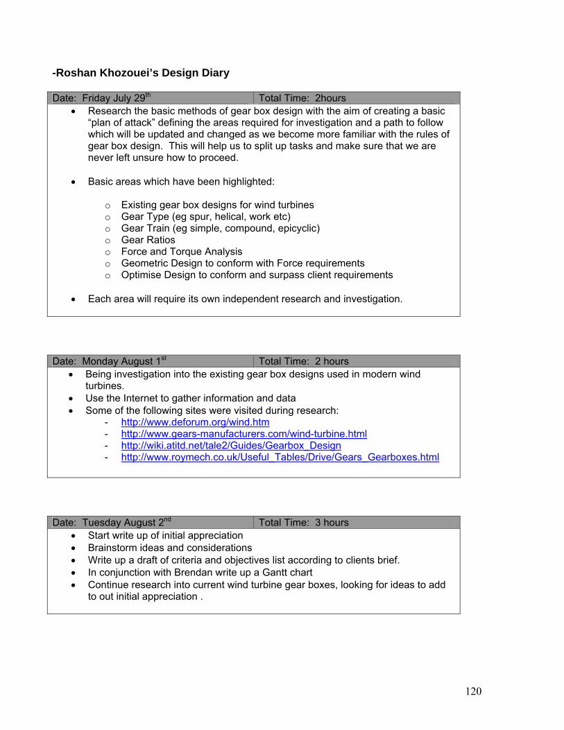
-Roshan Khozouei’s Design Diary Date: Friday July 29th Total Time: 2hours
• Research the basic methods of gear box design with the aim of creating a basic “plan of attack” defining the areas required for investigation and a path to follow which will be updated and changed as we become more familiar with the rules of gear box design. This will help us to split up tasks and make sure that we are never left unsure how to proceed.
• Basic areas which have been highlighted:
o Existing gear box designs for wind turbines o Gear Type (eg spur, helical, work etc) o Gear Train (eg simple, compound, epicyclic) o Gear Ratios o Force and Torque Analysis o Geometric Design to conform with Force requirements o Optimise Design to conform and surpass client requirements
• Each area will require its own independent research and investigation. Date: Monday August 1st Total Time: 2 hours
• Being investigation into the existing gear box designs used in modern wind turbines.
• Use the Internet to gather information and data • Some of the following sites were visited during research:
- http://www.deforum.org/wind.htm - http://www.gears-manufacturers.com/wind-turbine.html - http://wiki.atitd.net/tale2/Guides/Gearbox_Design - http://www.roymech.co.uk/Useful_Tables/Drive/Gears_Gearboxes.html
Date: Tuesday August 2nd Total Time: 3 hours
• Start write up of initial appreciation • Brainstorm ideas and considerations • Write up a draft of criteria and objectives list according to clients brief. • In conjunction with Brendan write up a Gantt chart • Continue research into current wind turbine gear boxes, looking for ideas to add
to out initial appreciation .
120

Date: Wednesday August 3nd Total Time: 3 hours
• Continue working on Initial appreciation • Finalising list of criteria and objectives • Confirming Gantt chart with group members • Brainstorming additional considerations
Date: Monday August 5thth Total Time: 2 hours • Continued research into current wind turbine gear box design. • Began research into suitable gear types, advantages and disadvantages. - Spur gears - Simple design, - High efficiency - Internal Spur – Similar to above, but allows for a more compact design - Used for Planetary gears - Helical - Similar properties to spur gears. - Drive results in axial thrust. - Gears are smoother and quieter for similar specifications to spur gear.
- They can run at high speeds and large diameters. - Have a higher torque/life capabilities for same size spur gears.
- Double Helical – Similar benefits to single helical but with no generated side thrust
- Higher Performance compared to single helical
Date: Thursday August 11th Total Time: 3.5 hours
• It has been decided to use a planetary, epicyclic gear box design • Spur gears have been chosen for the gear box design as they are simple and
cheap to manufacture and will fulfil all the clients requirements. • Investigate internal spur gears for use in planetary gear • Research equations specific to planetary gear box design, - Gear Ratio - Force and Torque equations for planetary gears etc • Begin to create a spreadsheet with all calculations and information required for
gear design including: - Dimensions for each gear (number of teeth, pitch radius) - Torques transferred at each stage - Forces generated between each pair of mating gears - Angular and linear velocity of each gear
121

] Date: Tuesday August 16th Total Time: 4 hours
• Continue working on spreadsheet for gearbox, fixing equations and updating information as it becomes available
• Worked on Hertzian stress equations for gears and input into spreadsheet • Worked on Bending stress equations for gears and input into spreadsheet - The above stress calculations will allow us to determine the minimum face width.
Both equations will output the required face width to withstand the particular stress and the larger face width will be the limiting factor when choosing out face width geometry.
Date: Thursday August 18th Total Time: 3 hours
• Continued to optimise our gearbox, so as to decrease its weight and size so that it fits into the required geometry defined by the client.
• Check for incorrect results in spreadsheet and fix bugs. • Fix errors in stress equations in spreadsheet • Begin consideration of gear manufacture.
Date: Monday August 22nd Total Time: 4.5 hours
• Approximate gear ratios were defined, and the spreadsheet was updated in conjunction with Brendan which would incorporate all equations that will determine the design of the gears. The spreadsheet was then iterated and the Diametral Pitch was changed until an optimum gear box was created.
• Determined the distribution of torque through the gear box - Input Arm: 760 kN - Planet Gear 1 (Three gears each experiencing) : 50.977628 kNm - Planets Gear 3 (Three gears each experiencing): -50.977628 kNm - Sun Gear: 45. 23367 kNm - Spur Gear 1: 45.23367 kNm - Spur Gear 2: 9.6330964 kNm • The Tangential Forces experienced by each gear mating: - Ring/Planets 1 : 361.25 kN - Plants 2/Sun : 127.203 kN - Spur 1/Spur2: 74.2022 kN
• Determined the Hertzian stresses experienced by the gear teeth, • Determined the Bending stress experienced by the gear teeth • From the above stresses we determined the limiting stress factor which then
allowed us to determine the face width of our gear teeth
122

- Minimum teeth width: - Ring and Planet 1 Gears: 242.588 mm - Planet 2 and Sun Gears: 168.8312 mm - Spur 1 and Spur 2 Gears: 124.71658 • The following criteria were optimised so to fulfil and surpass the clients
requirements - Gear box height - Gear box length - Gear box depth - Gear box mass • We reached the geometric optimisation for our gears - Total Mass: 5005.0119 kg - Overall Gear Box Height: 1840.0889 mm - Overall Gear Box Width: 1840.0889 mm
- Overall Gear Box Length : 595.58361 mm Date: Wednesday August 24th Total Time: 1 hours
• Prepare for Progress report
Date: Friday August 19th Total Time: 0.5 hours
• Finalise preparation for progress report
Date: Monday August 29th Total Time: 4 hours
• Began working on efficiency of gear box • We know Input power required is 1530 kW • Calculated required efficiency from peak Generator output - Generator is 98% efficient and has a peak output of 1300 kW, thus at its peak it
requires an input of 1300/0.98 kW = 1326.53 kW - Thus required efficiency is 86.7 % • Worked on power loss in our gear box. • Calculated Frictional losses •
Ring / Planet mate Planet / Sun mate Sun / Spur mate
Tangential Force (kN) 361.25878 127.2038 74.202215Pressure Angle 20 20 20Normal Force (kN) 384.4435638 135.3674565 78.96434787Friction Coefficient 0.03 0.03 0.03Friction Force (kN) 11.53330691 4.061023695 2.368930436Total Force (per stage) (kN) 34.59992074 12.18307109 2.368930436
123

Date: Wednesday August 31st Total Time: 2 hours
• Continued work on Efficiency • Began work on calculating sliding velocity - Sliding Velocity at initial point of contact - Calculating geometries at the initial point of contact - Calculating the initial velocity for each gear at the point of initial contact - Calculating the sliding velocity between each pair of mating gears at the time of initial contact
Date: Thursday September 1st Total Time: 3 hours
• Continued work on sliding velocity
- Sliding Velocity at point of final contact - Calculating geometries at the final point of contact - Calculating the velocity for each gear at the point of final contact - Calculating the sliding velocity between each pair of mating gears at the
time of final contact
Date: Friday September 2ndth Total Time: 2 hours
• Finalised calculation of power loss - Total Power loss was found to be 107.7 kW giving us an efficiency of
92.96 %. It was decided that as this is within the clients requirements we are happy with the outcome.
• Wrote up report for efficiency • Began working on calculating heat generation
Date: Wednesday September 7th Total Time: 7 hours
• Completed initial heat generation calculation. Temperature of gearbox operating under constant maximum speed is 436.6 degrees Celsius. This is very high and suggested to team the importance of cooling fins.
• Initiated report on heat generation. • Completed Seal investigation. Seals affected by temperature, pressure, shaft
material. 5 different type of seals used - Labyrinth, Felt, Lip, Ferro, Fluid, Mechanical
124

Date: Thursday September 8th Total Time: 8 hours
• Reiterated Heat generation calculation based on finalised housing parameters. With the effect of cooling fins, the operating temperature operating at constant full load dropped to 181.5 degrees Celsius.
• Gearbox sealing system decided. Seal required on main input, and output shafts. Lip seal to be specified due to the operating characteristics and cost.
• Completed write up on heat generation • Completed write up on seals • Compilation of reports with team members
125

APPENDIX E – Initial Appreciation
436-311/312: Engineering Design and Processes 2/ Design Methods 2 Design of Gearbox for a Wind Turbine
Initial Appreciation Introduction Gearboxes are devices used to modify torque-speed relationships of devices. In this project, the device is a Wind Turbine and a gearbox is required to match the requirements of the generator. Design Goal To design a gearbox to suit the Wind Turbine's parameters and operational requirments. (refer to handout) Objectives and Criteria The following is a list of objectives we aim to fulfill in this design along with their relevant criteria. Note: The objectives below are priortised from most important to least important and are listed from top to bottom respectively.
Objective Criteria Safety Minimise accidents Number of safety features
Number of accidents over fixed period of
time Minimise operator contact Frequency of operator service (times/year)
Time required to carry out service (Hrs) Maximise Product Performance Minimise Power Loss Power loss through gearbox (W) Maximise Reliability (Number of Failures/ Number of Units)
Number of control systems/ feedback sensors
Minimise Torque Fluctuations % Over/Under shoot Meet Design Requirements % of requirements met Maximise Durability Lifetime of Design Time (Years) Prone to Corrosion % mass deteriorated over lifetime Optimal Operating Temperature Temperature (oC) Seal Performance Gear oil lost over lifetime (mL) Operating Vibration Acceleration (m/s2) Oil Performance Service Life before deterioration (Years) Optimise Size/ Weight Optimise Weight Weight (Kg) Minimise Size Volume Consumed (m3)
126
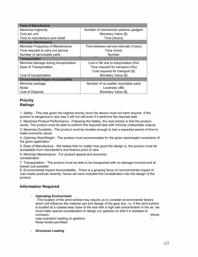
Ease of Manufacture Maximise Ingenuity Number of mechanical systems/ gadgets Cost per unit Monetary Value ($) Time to manufacture and install Time (Hours) Minimise Maintenance Minimise Frequency of Maintenance Time between service intervals (Years) Time required to carry out service Time (mins) Number of serviceable parts Number Transportation Minimise damage during transportation Lost in life due to tranportation (Hrs Ease of Transportation Time required for transport (Hrs)
Cost required for transport ($) Cost of transportation Monetary Value ($) Environmental Impact Accountability Minimise wastage Number of re-usable/ recyclable parts Noise Loudness (dB) Cost of Disposal Monetary Value ($) Priority Ratings 1. Safety - This was given the highest priority since the device must not harm anyone. If the product is dangerous in any way it will not sell even if it performs the required task 2. Maximise Product Performance - Following the Safety, the next priority is that the product works. The product must be able to perform the required task with minimal undesirable outputs 3. Maximise Durability - The product must be durable enough to last a expected period of time to make economic sense 4. Optimise Size/Weight - The product must accommodate for the given size/weight constraints of the given application 5. Ease of Manufacture - We realise that no matter how good the design is, the product must be acceptable from manufacter's and finance point of view 6. Minimise Maintenance - For product appeal and economic consideration 7. Transportation - The product must be able to be transported with no damage incurred and at lowest cost possible 8. Environmental Impact Accountability - There is a growing focus on environmental impact of man-made products recently, hence we have included this consideration into the design of the product Information Required
- Operating Environment
-The location of the wind turbine may require us to consider environmental factors which will influence the material use and design of the gear box. i.e. If the wind turbine is located at a coastal area close to the sea with a high salt concentration in the air, we must make special consideration to design our gearbox so that it is resistant to corrosion. -Worst case scenario/ loading on gearbox - Noise levels permitted
- Structural Loading
127

Will all the stresses imposed on the main shaft (due to rotor/blade) be offset by the main bearing or will some of it be offset by ie. gearbox? Will there be any centrifugal forces created by the operation of the gearbox?
- Commercially Available/Manufacturable Components
Details on comercially available gears, shafts, bearings, seals, lubricants and/or manufacturing capabilities on custom parts (ie. Housing)
- Dimension/ Weight Limitations
What are the dimensional and weight limitiations of the gearbox?
- Expected Working Life How long is this gearbox expected to work before overhaul/ maintenance etc?
Subproblems Foreseen
- Transportation
If the part is assembled before transportation the design must make considerations for damage which may occur during transportation due to vibration and unlikely movement of the part. Also will the part require its own special mode of transportation which will influence the design of the part and will increase the overall cost.
- Housing Design
-The housing design must accommodate for transportation of the part by use of lifting lugs or other design features. As such the housing must be designed so that during lifting no stresses are imparted to the bearings and shafts in the gearbox. -Housing design must also make considerations as to how it will mount onto the nacelle and the load it will impose on the supporting structure. -Additionally within the housing, it must be able to support the shafts, gears and bearings inside.
- Optimal Moment of Inertia/ NVH
-The moment of inertia of the parts will effect the responsiveness of the wind turbine. A high moment of inertia will require a longer amount of time to get up to speed however the turbine shall continue to turn once the wind dies down dissipating this energy. A optimal balance needs to be found based on operating parameters of wind turbine. -Noise/Vibration/Harshness of the gearbox will also be a issue if the gearbox components are 'too' light or/if natural frequencies of sub components create damaging system level resonanances
- Monitoring Gearbox Vitals
Essential operating parameters of the gearbox needs to be determined, so that a warning/maintenance system can be established for reliable operation.
- Gear Design/ Calculations/ Selection
Task selecting gear type, number of stages, calculation of gear ratios to suit wind
128

turbine operating parameters and given constraints. Then problem of finding comerically available gears to match requirement
- Shaft Design/ Calculation/ Selection
Task of calculating and selecting required shaft diameter/ material that can withstand required torque loading
- Lubrication/ Seals/ Bearings
Task of selecting appropriate lubrication system, seals and bearings
- Designing against Failure
Assigning different safety factor levels for different components
129

APPENDIX F – Assembly Drawings
130

APPENDIX G – Material Properties
131

APPENDIX H – SIN Diagram
132