Forming - · PDF fileDifferentiation of blanking and perforating blanking piercing waste...
31
Seite 1 © WZL / IPT Forming - Blanking Manufacturing Technology II Lecture 6 Laboratory for Machine Tools and Production Engineering Chair of Manufacturing Technology Prof. Dr.-Ing. Dr.-Ing. E.h. F. Klocke Seite 2 © WZL / IPT Content Introduction Demands on blanking parts Shearing Fine blanking Laser cutting Water-jet cutting
Transcript of Forming - · PDF fileDifferentiation of blanking and perforating blanking piercing waste...

1
Seite 1© WZL / IPT
Forming - Blanking
Manufacturing Technology II
Lecture 6
Laboratory for Machine Tools and Production Engineering
Chair of Manufacturing Technology
Prof. Dr.-Ing. Dr.-Ing. E.h. F. Klocke
Seite 2© WZL / IPT
Content
Introduction
Demands on blanking parts
Shearing
Fine blanking
Laser cutting
Water-jet cutting

2
Seite 3© WZL / IPT
Deep DrawingIroningSpinningHydroformingWire DrawingPipe DrawingCollar Forming
Casting Forming Cutting Joining Coating Changing of Material Properties
CompressiveForming
Tenso-Compressive
Forming
TensileForming Bend Forming Shear
Forming Severing
TranslateTwistIntersperse
Manufacturing Processesaccording to DIN 8580ff
Open DieForgingClosed Die ForgingCold Extrusion Rod ExtrusionRollingUpsettingHobbingThread Rolling
Stretch FormingExtendingExpandingEmbossing
With linear Tool MovementWithrotating Tool Movement
ShearingFine BlankingCutting with a single BladeCutting withtwo approachingBladesSplittingTearing
IntroductionSheet Forming Process
Seite 4© WZL / IPT
IntroductionWhat is blanking?
Definition:
Mechanical separation of workpieces without appearance of shapeless material, therefore without chips … if necessary, including additional forming-operations.

3
Seite 5© WZL / IPT
Content
Introduction
Demands on blanking parts
Shearing
Fine blanking
Laser cutting
Water-jet cutting
Seite 6© WZL / IPT
Demands on blanking partsRequired quality of blanking parts
surface evenness
smooth sheared zone
cutting burr
rupture zone
draw-in
achievableroughness
angular deviation

4
Seite 7© WZL / IPT
Content
Introduction
Demands on blanking parts
Shearing– Introduction– Characterisation of the process– Achievable accuracy– Forces in shearing– Wear– Tool design– Examples of sheared parts
Fine blanking
Laser cutting
Water-jet cutting
Seite 8© WZL / IPT
Shearing - IntroductionShearing – Introduction
application IT-classification costs output
Shearing
high
rough (IT 11) low high
lowfine (IT 7)
shearedsurface

5
Seite 9© WZL / IPT
Shearing - Characterisation of the processOpen and closed cut in shearing
open cut closed cut
tool flank open flank
Seite 10© WZL / IPT
Shearing - Characterisation of the processDifferentiation of blanking and perforating
blanking piercing
waste
waste

6
Seite 11© WZL / IPT
Shearing - Characterisation of the processTool design of shearing
punch
sheet metal
blanking die
u – die clearenceapp. 0,05 x sheet thicknesswith:u = ½ · (a – a1)
a – dimension of cutting die
a1 – punch dimension
α – relief angle of cutting die
Ublank holder
Seite 12© WZL / IPT
Shearing - Characterisation of the processProcess sequences of shearing
1 2
3 4
charging of the punch
elastic& plasticdeformation
shearing& cracking
break through

7
Seite 13© WZL / IPT
Shearing - Characterisation of the process
Stresses in shearing
cuttingdie
punch
F
F
τ
τσ σ
shearing and tensile stresses cause cracking
Seite 14© WZL / IPT
Shearing – Achievable accuracyErrors on sheared workpieces
burr height hG
draw-in height hE
draw-in
shearing zone
rupture zone
ttRR
hhGG
hhEE
crack depth tR

8
Seite 15© WZL / IPT
Shearing – Achievable accuracyInfluence of die clearance on the sheared surfaces
smallclearance
bigclearance
By a small die clearance, distortion wedges are generated by squeezing of a the material between two cracks.
no formation of distortion wedge
formation of distortion wedge
Seite 16© WZL / IPT
Shearing – Achievable accuracyQuality of sheared surface depending on specific die clearance
spec
ific
die
clea
ranc
e:
die
clea
ranc
eu S
/ she
etth
ickn
ess
s

9
Seite 17© WZL / IPT
Shearing – Achievable accuracyInfluence of specific die clearance on crack depth
blanking
specific die clearance us / %
Cra
ck d
epth
t Rsh
eett
hick
ness
s
Seite 18© WZL / IPT
Shearing – Achievable accuracyRelation between burr height and number of cuts
ductilesheet
brittlesheet
burr height
10
Seite 19© WZL / IPT
Shearing - Forces in shearingReduction of cutting force by modification of tools
Contact between punch and sheet
slopedcut
planecut
s h
total punch stroke
forc
e F
0 s 2s 3s
0,3 Fmax
0,6 Fmax
0,9 Fmax
Fmaxh = 0 (plane cut)
h = 1/3 s (sloped cut)
h = s (sloped cut)
h = 2s(sloped cut)
=
work s(h=0) = work s(h=2s)
Due to workpiece-bending, sloped cut is only suited for piercing.
Seite 20© WZL / IPT
Shearing - Forces in shearingReduction of cutting force by modification of tools
conical punchgrooved punchplane cut sloped cut
conical die grooved die punch offset

11
Seite 21© WZL / IPT
Shearing - Forces in shearingDependence of quality on shearing strength of carbon steel
carbon concentration tensile strenght breaking elongation sheet thickness
die clearance part diameter aspect ratio draw-in
Cutting resistance is defined as the cutting force (Fs) referring to the cutting surface (As= ls*s)
Seite 22© WZL / IPT
Shearing – WearWear on the punch
wear on shaft area
wear on front facefatigue wear on front face
fatigue wear and wear on front face espacially appear for lowersheet thickness (s < 2 mm)
wear on shaft area is caused byfriction between punch and sheetin direction of punch movement. Appears during cutting of thickersheets (s ≥ 2 mm)

12
Seite 23© WZL / IPT
open cut
Workpiece
Shearing – wearInfluences on wear
Source: reiner, Müller Weingarten, Feintool
Tool Machine
Type of process
tool wear
materialhardnesssurfaceguidancedie clearance
stiffnesskinematics
alloystiffnesshardnessdimensionshape
open cutclosed cut
closed cut
Seite 24© WZL / IPT
Shearing – Tool design
Multi-stage blanking tool
4 stageMulti-stage blanking toolfor shearing of rotor- and stator-sheets
stator rotor

13
Seite 25© WZL / IPT
Shearing - Examples of sheared partsMulti-stage cut including assembly of an electronic connector
Gesamtlaufzeit1:49 min
Seite 26© WZL / IPT
Content
Introduction
Demands on blanking parts
Shearing
Fine blanking– Introduction– Characterisation of the process– Process details and degree of difficulty– Achievable accuracy– Field of application– Tool design– Production examples
Laser cutting
Water-jet cutting

14
Seite 27© WZL / IPT
Fine blanking - IntroductionFine blanking - Introduction
application IT-classification costs output
shearing
fine blanking
high
rough (IT 11) low high
lowfine (IT 7)
shearedsurface
Seite 28© WZL / IPT
Fine blanking – Characterisation of the processAnimation of fine blanking
clamping
plastic deformation
cutting

15
Seite 29© WZL / IPT
Fine blanking – Characterisation of the processStresses in fine blanking
cutting die
punch
F
F
τ
τσ σ
counterpunch
blankholderwith veering
F
F
σ
σ
σ
σ
σ
σ
σ
σ
σ
σ
superposed compression prevents cracking
Seite 30© WZL / IPT
fine fine blankingblankingshearingshearing
1 – cutting die(2 – guiding plate)3 – punch
FS – punch force
1 – cutting die2 – vee ring and
blank holder3 – punch4 – counter punch
FS – punch forceFR – vee ring and blank
holder forceFG – counter punch
force
Fine blanking – Characterisation of the processDifferences between shearing and fine blanking
die clearance5% 0,5%

16
Seite 31© WZL / IPT
Fine blanking – DetailsGeometry of vee rings
thin sheets
thick sheets
sheet thickness s5 – 15 mm
sheet thickness s3 – 5 mm
blank holderwith vee ring
cutting die
• create compression stresses• prevent horizontal movement of the
sheet / material flow
vee ringcutting line
toothed
inward notch
outward notch
vee ring cutting line
intention:
Seite 32© WZL / IPT
Fine blanking - DetailsDependence of workpiece quality on influencing quantities
counter punch force draw-in width draw-in height
smooth shearingzone deflexion
Process parameters affect workpiece quality:example:
draw-in height die clearance sheet thickness
blank holder force counter punchforce
Workpiece quality can be influenced by process parameters:example:
17
Seite 33© WZL / IPT
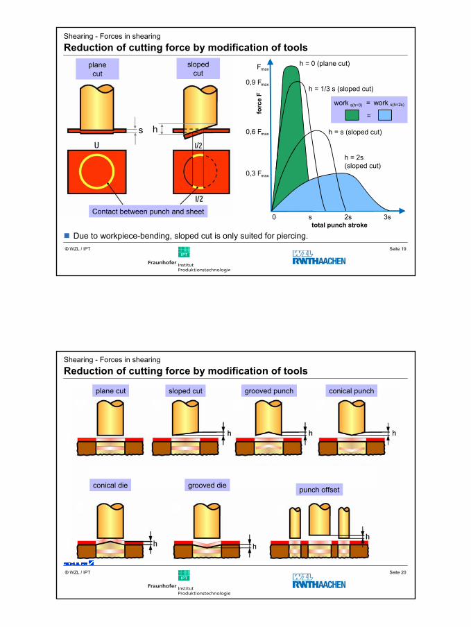
Fine blanking – obtainable precisionDefinition of degree of difficulty in fine blanking
slot
a, s
tick
b / m
m
sheet thickness s / mm
edge
radi
usr i
, ra
/ mm
sheet thickness s / mm
degree of difficultyS1 – easyS2 – mediumS3 – difficultedge angle a
Seite 34© WZL / IPT
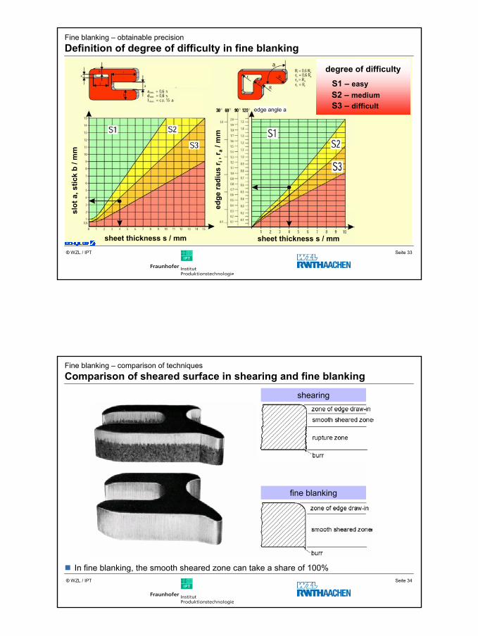
Fine blanking – comparison of techniquesComparison of sheared surface in shearing and fine blanking
shearing
fine blanking
In fine blanking, the smooth sheared zone can take a share of 100%

18
Seite 35© WZL / IPT
Fine blanking –applicationApplication examples
fine blanking
shearing
In fine blanking, the sheared surface can be used as a functional surface
Seite 36© WZL / IPT
Fine blanking – Field of applicationApplication examples in automotive industry
valve plate
gear shifting gate door lock window lift
synchronising disc
belt pretensioner
ABS-pulse generator
cooling systemseat belt componentsseat adjustment
brakes
gear

19
Seite 37© WZL / IPT
Fine blanking – Tool designExample for a compound press tool
In fine blanking, several cuts can be done at the same time.
Seite 38© WZL / IPT
Fine blanking – Tool designCompound press tool – disc brake

20
Seite 39© WZL / IPT
Fine blanking – Tool designExample for a multi-stage tools
fine blanking of a disc using multi-stage tool fine blanking of a clutch disc
stage 1: fine blankingstage 2: burr stamping
stage 1
stage 2
Feeddirection
Seite 40© WZL / IPT
Fine blanking – Tool design
follow-on composite tool3 stages in a Follow-on composite tool
forming –thread forming –fine blanking
connecting strap of a car door

21
Seite 41© WZL / IPT
Gesamtlaufzeit2:13 min
Fine blanking – Production examplesProduction of a clutch disc
Seite 42© WZL / IPT
combined fine blanking / forming
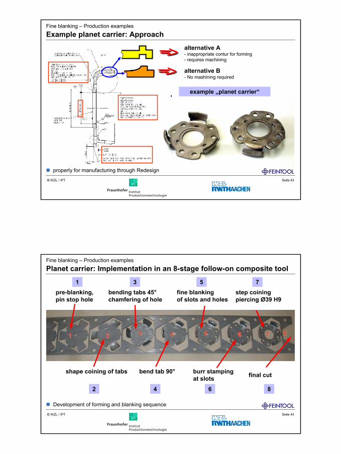
Fine blanking – Production examplesPlanet carrier: Starting point
A combination of fine blanking and forming realises the production of complex parts
22
Seite 43© WZL / IPT
example „planet carrier“
alternative A- inappropriate contur for forming- requires machining
alternative B- No mashining required
Fine blanking – Production examples
Example planet carrier: Approach
properly for manufacturing through Redesign
Seite 44© WZL / IPT
Fine blanking – Production examples
Planet carrier: Implementation in an 8-stage follow-on composite tool
pre-blanking, pin stop hole
bending tabs 45°chamfering of hole
fine blankingof slots and holes
step coiningpiercing Ø39 H9
shape coining of tabs bend tab 90° burr stampingat slots final cut
1
2
3
4
5
6
7
8
Development of forming and blanking sequence

23
Seite 45© WZL / IPT
Fine blanking – Production examplesPlanet carrier: Follow-on composite tool in modular design
bottom tool upper tool
Seite 46© WZL / IPT
Fine blanking – Production examplesPlanet carrier: Follow-on composite tool in modular design
1 2 3 4 5 6 7 8
stages / module
24
Seite 47© WZL / IPT
Content
Introdution
Demands on blanking parts
Shearing
Fine blanking
Laser cutting
Water-jet cutting
Seite 48© WZL / IPT
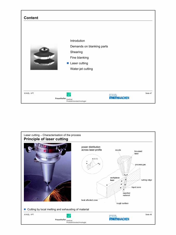
Laser cutting – Characterisation of the processPrinciple of laser cutting
Cutting by local melting and exhausting of material
power power distributiondistributionacrossacross laserlaser--profileprofile

25
Seite 49© WZL / IPT
Laser cutting – process variablesCutting speed for several materials
CO2-laser, PL max = 2,6 kW
12
8
4
0 84 12 16 20
feed
spee
dv f
/ m min
sheet thickness s / mm
structural steel (O2 0,5 – 4 bar)CrNi - steel (O2 0,5 – 4 bar)Al. - alloy (O2 10 – 18 bar)
Top feed speed depends on material and sheet thickness
Seite 50© WZL / IPT
15
10
5
0 84 12 16 20
feed
spee
dv f
/ m min
sheet thickness structural steel s / mm24
20
Laser cutting – process variablesComparison of cutting speeds
shearinglaser cutting (1500 W)water-jet cutting
Top feed speed depends on material and sheet thicknessQuelle: TrumpfQuelle: Trumpf

26
Seite 51© WZL / IPT
special process:rotational cutting
St37465mm x 5400mm x 2mm
contourA
B
C
shearing(rotational)
30 sec
4 sec
3 sec
laser cut
17 sec
16 sec
12 sec
nibbling
40 sec
-
15 sec
flexibility
speed
Laser cutting – Process comparisonComparision shearing - nibbling - laser beam cutting
Seite 52© WZL / IPT
Laser cutting – process variablesComparison of machinable sheet thicknesses
structural steelhigh-grade steelaluminium
shearing
laser-jetcutting(1500 W)
laser-jetcutting(2600 W)
water-jetcutting
0 20 40 60 80sheet thickness / mm
Quelle: TrumpfQuelle: Trumpf

27
Seite 53© WZL / IPT
Laser cutting – Field of applicationExamples of series production
electronic connector (low lot sizes)
climbing clamp
synchronising disc
stator sheet for special enginesQuelle: tecnologix
Seite 54© WZL / IPT
Content
Introdution
Demands on blanking parts
Shearing
Fine blanking
Laser cutting
Water-jet cutting

28
Seite 55© WZL / IPT
principle
water supply
abrasive medium
mixing pipeguard
Water-jet cutting – Characterisation of the processSystem design
Seite 56© WZL / IPT
Verrundung derSt rahleintrit t skante
Konizität der Schnit t fuge
Abplatzungen amStrahlaust rit t
Riefen, Auswaschungen,Risse auf Schnit t f lächen
Quellenangabe: XYZ
Water-jet cuttingProperties of the jet groove
rounding off at the jet entry
beveled hole
chipping at the exit
scoring, erosion and cracks on thesurface

29
Seite 57© WZL / IPT
Water-jet cuttingcutted surfaces and gaps
1
2
1
2
vf = 20 mm/min
Rz,1 = 25 µm
Rz,2 = 30 µm
vf = 200 mm/min
Rz,1 = 25 µm
Rz,2 = 140 µm
surface gap
material : AlMgSiO.5 abrasive medium : Granat 80 Meshsheet thickness : 25 mm mass flow : 400 g/min
pressure : 300 MPa
feed speed
The surface quality is heavily dependent on the feed speed
Seite 58© WZL / IPT
Water-jet cutting – process parametersCharacteristic of the surface
α : angle of shoulderbG : burr widthb0 : width of „jet influenced zone“bSO : notch width on workpiece topbSu : notch width on workpiece bottom
hG : burr heightR0 : edge radiusu : rectangular and inclination toleranceM : measuring range of u s : sheet thickness

30
Seite 59© WZL / IPT
Water-jet cutting – influencing parametersInfluences on notch width
0,5
1
1,5
2
2,5
3
3,5
0 2 4 6 8 10 12 0 2 4 6 8 10 12
0,5
1
1,5
2
2,5no
tch
wid
thb S
O/ m
m
notc
hw
idth
b SU
/ mm
treatment distance aD / mm treatment distance aD / mm
pressure : 300 MPa focussing pipe diameternozzle diameter : 0,3 mm d = 1,8 mmlenght of focussing pipe : 50 mmfeed speed : 50 mm / min d = 1,5 mmabrasive medium : Granat 80 Meshmass flow : 250 g / min d = 1,2 mmmaterial : AlMgSi0.5sheet thickness : 5 mm d = 0,8 mm
Seite 60© WZL / IPT
Water-jet cutting – DependencesDependence of surface quality on particle size

31
Seite 61© WZL / IPT
nozzle diameter : 0,3 mm materiallenght of focussing pipe : 50 mm : AlMgSi0.5abrasive medium : Granat 80 Mesh : TiAl6V4mass flow : 250 g / min : 1.4375
Water-jet cutting – Performance characteristicPerformance characteristics of different materials
00 150 200 250 300
20
40
60
80
00 150 200 250 300
20
40
60
80
feed speed / mm/minpressure / MPa
dept
hof
not
chh K
/ mm
dept
hof
not
chh K
/ mm