
Blanking Plugs - Forum Energy Technologies · Bypass Blanking Plugs with Removal Mandel . A B ...
21
Blanking Plugs
Transcript of Blanking Plugs - Forum Energy Technologies · Bypass Blanking Plugs with Removal Mandel . A B ...

Blanking Plugs
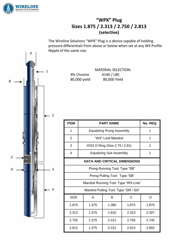
“WPX” Plug Sizes 1.875 / 2.313 / 2.750 / 2.813
(selective)
The Wireline Solutions “WPX” Plug is a device capable of holding pressure differentials from above or below when set at any WX Profile Nipple of the same size.
MATERIAL SELECTION: 9% Chrome 4140 / L80 80,000 yield 80,000 Yield
ITEM PART NAME No. REQ.
1 Equalizing Prong Assembly 1
2 “WX” Lock Mandrel 1
3 #033 O-Ring (Size 2.75 / 2.81) 1
4 Equalizing Sub Assembly 1
DATA AND CRITICAL DIMENSIONS
Prong Running Tool: Type “SB”
Prong Pulling Tool: Type “SB”
Mandrel Running Tool: Type “WX-Line”
Mandrel Pulling Tool: Type “GR / GS”
SIZE A B C D
1.875 1.375 1.380 1.875 1.870
2.313 1.375 1.810 2.313 2.307
2.750 1.375 2.312 2.750 2.745
2.813 1.375 2.312 2.813 2.802
4
1
2
3
C
D
B
A
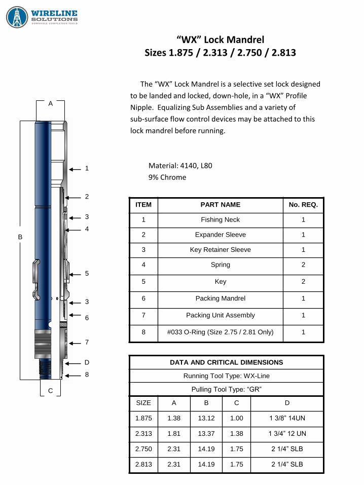
“WX” Lock Mandrel Sizes 1.875 / 2.313 / 2.750 / 2.813
The “WX” Lock Mandrel is a selective set lock designed
to be landed and locked, down-hole, in a “WX” Profile
Nipple. Equalizing Sub Assemblies and a variety of
sub-surface flow control devices may be attached to this
lock mandrel before running.
Material: 4140, L80
9% Chrome
ITEM PART NAME No. REQ.
1 Fishing Neck 1
2 Expander Sleeve 1
3 Key Retainer Sleeve 1
4 Spring 2
5 Key 2
6 Packing Mandrel 1
7 Packing Unit Assembly 1
8 #033 O-Ring (Size 2.75 / 2.81 Only) 1
SIZE A B C D
1.875 1.38 13.12 1.00 1 3/8” 14UN
2.313 1.81 13.37 1.38 1 3/4” 12 UN
2.750 2.31 14.19 1.75 2 1/4” SLB
2.813 2.31 14.19 1.75 2 1/4” SLB
DATA AND CRITICAL DIMENSIONS
Running Tool Type: WX-Line
Pulling Tool Type: “GR”
A
1
2
3
4
5
3
6
7
D
8
C
B
“WX” Lock Mandrel Sizes 1.875 / 2.313 / 2.750 / 2.813
The type “WX” Locking Mandrels are selective set lock mandrels designed to be landed down
hole in a selected “WX” Landing Nipple profile. The “WX” Lock is available with various sub
surface plug assemblies and flow control accessories. The “WX” Lock is designed for standard
weight tubing and service pressures. The Lock is made Selective by use of the WX-Line Running
Tool. They may be installed in any selected “WX” profile anywhere in the tubing string.
OPERATION
The selective locating system is designed into the WX-Line Running Tool using a set of Locating
Dogs on exterior of running tool. After the “WX” Lock is made up on the WX-Line Running Tool it is
lowered into well to selected “WX” Nipple. As the packing section of the lock is passed through the
landing nipple, the restriction is noticed by wireline operator. After selected nipple is located, the
tool string should be lowered through the nipple and stopped. The tool string should then be raised
slowly until tool stops, indicating locking dogs of running tool are on the lower end of Nipple. An
upward strain on the tool string will trip the locating dogs on the running tool and the lock mandrel
keys move into the locating position. With the lock mandrel keys now in the control position, raise
tool string 3 to 6 feet above the nipple and lower back into nipple until the mandrel keys reach
nipple profile. As the mandrel reaches the profile, the key springs move the keys into the profile
and stop the tool string. Jar downward at this time and shear the upper pin in running tool and
allow Expander Sleeve of lock mandrel to move down and be driven behind the mandrel keys.
When the Expander Sleeve is driven behind the mandrel keys, serrations retain the sleeve in the
locked position. Placing an upward strain on the tool string will determine the lock is locked in
place. If the mandrel cannot be pulled, jar upward and shear the shear pin on the lower end of
running tool allowing the tool string to come out of hole. If lock mandrel returns to surface with
running tool, it has not been properly set.
(continued on next page)
“WX” Lock Mandrel Sizes 1.875 / 2.313 / 2.750 / 2.813
PULLING
The type GR (Shear Up) and GS (Shear Down) Running / Pulling Tool is used to retrieve a “WX”
Lock Mandrel. The GR or GS Pulling Tool is lowered down to lock and dogs of the pulling tool
engage the internal fishing neck of the lock. After engagement, upward jarring on the pulling tool
picks up the Expander Sleeve moving it from behind the mandrel keys and allows the keys to
retract. At this time, lock mandrel should be able to be retrieved. NOTE: Measures must be taken
that whatever plug device or flow control accessories that have been run in conjunction with “WX”
Lock have been equalized before attempting to pull.
“WX” Lock Mandrel Sizes 1.875 / 2.313 / 2.750 / 2.813
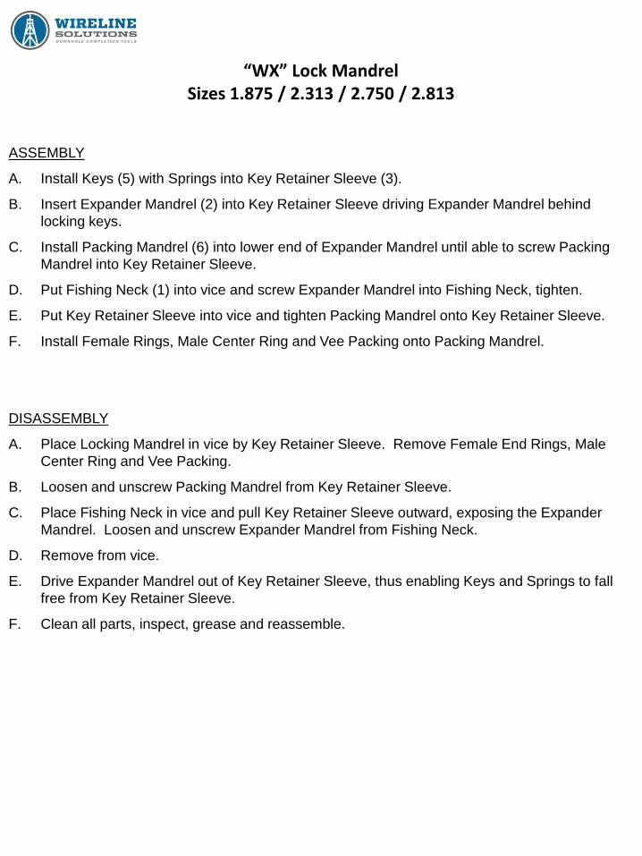
ASSEMBLY
A. Install Keys (5) with Springs into Key Retainer Sleeve (3).
B. Insert Expander Mandrel (2) into Key Retainer Sleeve driving Expander Mandrel behind
locking keys.
C. Install Packing Mandrel (6) into lower end of Expander Mandrel until able to screw Packing
Mandrel into Key Retainer Sleeve.
D. Put Fishing Neck (1) into vice and screw Expander Mandrel into Fishing Neck, tighten.
E. Put Key Retainer Sleeve into vice and tighten Packing Mandrel onto Key Retainer Sleeve.
F. Install Female Rings, Male Center Ring and Vee Packing onto Packing Mandrel.
DISASSEMBLY
A. Place Locking Mandrel in vice by Key Retainer Sleeve. Remove Female End Rings, Male
Center Ring and Vee Packing.
B. Loosen and unscrew Packing Mandrel from Key Retainer Sleeve.
C. Place Fishing Neck in vice and pull Key Retainer Sleeve outward, exposing the Expander
Mandrel. Loosen and unscrew Expander Mandrel from Fishing Neck.
D. Remove from vice.
E. Drive Expander Mandrel out of Key Retainer Sleeve, thus enabling Keys and Springs to fall
free from Key Retainer Sleeve.
F. Clean all parts, inspect, grease and reassemble.
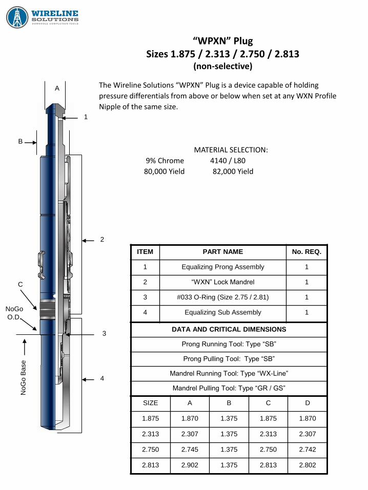
“WPXN” Plug Sizes 1.875 / 2.313 / 2.750 / 2.813
(non-selective)
The Wireline Solutions “WPXN” Plug is a device capable of holding
pressure differentials from above or below when set at any WXN Profile
Nipple of the same size.
MATERIAL SELECTION:
9% Chrome 4140 / L80
80,000 Yield 82,000 Yield
ITEM PART NAME No. REQ.
1 Equalizing Prong Assembly 1
2 “WXN” Lock Mandrel 1
3 #033 O-Ring (Size 2.75 / 2.81) 1
4 Equalizing Sub Assembly 1
DATA AND CRITICAL DIMENSIONS
Prong Running Tool: Type “SB”
Prong Pulling Tool: Type “SB”
Mandrel Running Tool: Type “WX-Line”
Mandrel Pulling Tool: Type “GR / GS”
SIZE A B C D
1.875 1.870 1.375 1.875 1.870
2.313 2.307 1.375 2.313 2.307
2.750 2.745 1.375 2.750 2.742
2.813 2.902 1.375 2.813 2.802
A
1
B
C
NoGo
O.D.
NoG
o B
ase
2
3
4
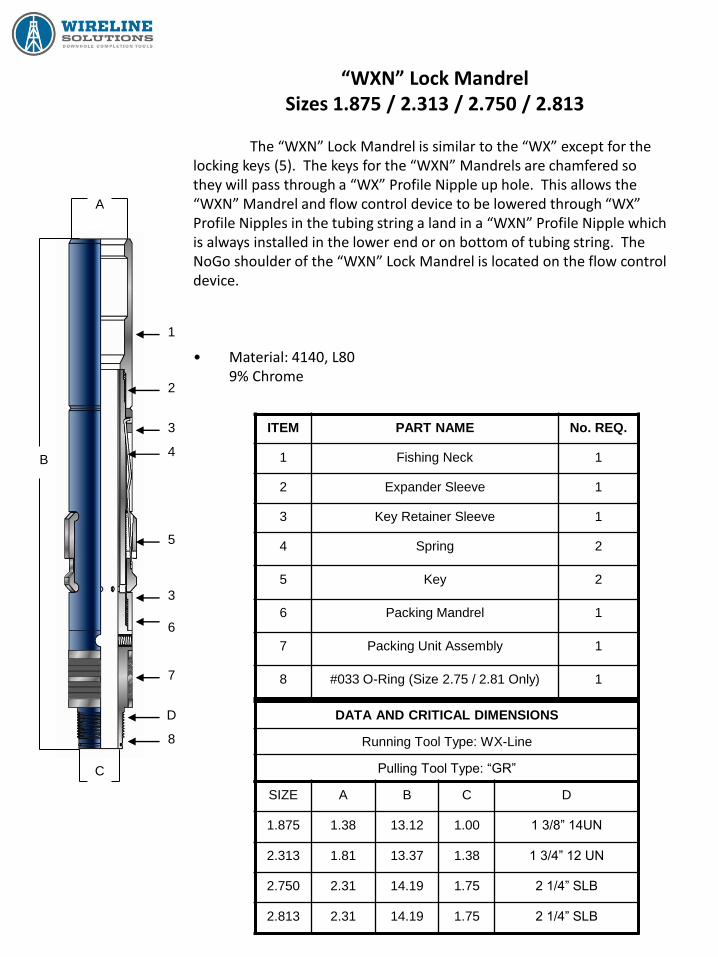
“WXN” Lock Mandrel Sizes 1.875 / 2.313 / 2.750 / 2.813
The “WXN” Lock Mandrel is similar to the “WX” except for the
locking keys (5). The keys for the “WXN” Mandrels are chamfered so they will pass through a “WX” Profile Nipple up hole. This allows the “WXN” Mandrel and flow control device to be lowered through “WX” Profile Nipples in the tubing string a land in a “WXN” Profile Nipple which is always installed in the lower end or on bottom of tubing string. The NoGo shoulder of the “WXN” Lock Mandrel is located on the flow control device. • Material: 4140, L80 9% Chrome
ITEM PART NAME No. REQ.
1 Fishing Neck 1
2 Expander Sleeve 1
3 Key Retainer Sleeve 1
4 Spring 2
5 Key 2
6 Packing Mandrel 1
7 Packing Unit Assembly 1
8 #033 O-Ring (Size 2.75 / 2.81 Only) 1
SIZE A B C D
1.875 1.38 13.12 1.00 1 3/8” 14UN
2.313 1.81 13.37 1.38 1 3/4” 12 UN
2.750 2.31 14.19 1.75 2 1/4” SLB
2.813 2.31 14.19 1.75 2 1/4” SLB
DATA AND CRITICAL DIMENSIONS
Running Tool Type: WX-Line
Pulling Tool Type: “GR”
A
1
2
3
4
5
3
6
7
D
8
C
B
“WXN” Lock Mandrel Sizes 1.875 / 2.313 / 2.750 / 2.813
The type “WXN” Locking Mandrels are similar to the “WX” except for the locking keys. The
“WXN” keys are chamfered so they will pass through a “WX” nipple. In addition, the equalizing
valve of the flow control accessory which is made up onto the “WXN” locks serves as a locating
device for the lock when it contacts the NoGo restriction of the “WXN” Nipple. The “WXN” lock is
designed for standard weight tubing and service pressures. The “WXN” Nipple is always installed
in or on the bottom of the tubing string and the chamfered keys of the “WXN” lock allows the lock to
pass through any “WX” nipple above.
OPERATION
The same WX-Line Running Tool is utilized to run the “WXN” Lock. After the “WXN” Lock is
made up on the WX-Line Running Tool, the running tool must be placed into the “control” position
by hand before running. To do this, pull the outer sleeve of the running tool downward until the
upper dogs fall into the recess on the inner mandrel, and the keys of the lock will move from a
retracted to an expanded position. The lock mandrel is run directly down into the “WXN” Nipple.
When the NoGo shoulder of the equalizing valve contacts the NoGo restriction of the “WXN”
Nipple, jarring down will shear the upper pin in the running tool and allow the expander sleeve to be
driven down behind the mandrel keys, serrations retain the sleeve in the locked position. Placing
an upward strain on the tool string will determine the lock is locked in place. If the mandrel cannot
be pulled, jar upward and shear the shear pin on the lower end of running tool allowing the tool
string to come out of hole. If lock mandrel returns to surface with running tool, it
has not been properly set.
PULLING
The type GR (Shear Up) and GS (Shear Down) Running / Pulling Tool is used to retrieve a
“WXN” Lock Mandrel. The GR or GS Pulling Tool is lowered down to lock and dogs of the pulling
tool engage the internal fishing neck of the lock. After engagement, upward jarring on the pulling
tool picks up the Expander Sleeve moving it from behind the mandrel keys and allows the keys to
retract. At this time, lock mandrel should be able to be retrieved. NOTE: Measures must be taken
that whatever plug device or flow control accessories that have been run in conjunction with
“WXN” Lock have been equalized before attempting to pull.

“WXN” Lock Mandrel Sizes 1.875 / 2.313 / 2.750 / 2.813
ASSEMBLY
A. Install Keys (5) with Springs into Key Retainer Sleeve (3).
B. Insert Expander Mandrel (2) into Key Retainer Sleeve driving Expander Mandrel behind
locking keys.
C. Install Packing Mandrel (6) into lower end of Expander Mandrel until able to screw Packing
Mandrel into Key Retainer Sleeve.
D. Put Fishing Neck (1) into vice and screw Expander Mandrel into Fishing Neck, tighten.
E. Put Key Retainer Sleeve into vice and tighten Packing Mandrel onto Key Retainer Sleeve.
F. Install Female Rings, Male Center Ring and Vee Packing onto Packing Mandrel.
DISASSEMBLY
A. Place Locking Mandrel in vice by Key Retainer Sleeve. Remove Female End Rings, Male
Center Ring and Vee Packing.
B. Loosen and unscrew Packing Mandrel from Key Retainer Sleeve.
C. Place Fishing Neck in vice and pull Key Retainer Sleeve outward, exposing the Expander
Mandrel. Loosen and unscrew Expander Mandrel from Fishing Neck.
D. Remove from vice.
E. Drive Expander Mandrel out of Key Retainer Sleeve, thus enabling Keys and Springs to fall
free from Key Retainer Sleeve.
F. Clean all parts, inspect, grease and reassemble.
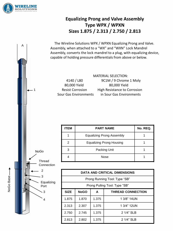
Equalizing Prong and Valve Assembly Type WPX / WPXN
Sizes 1.875 / 2.313 / 2.750 / 2.813
The Wireline Solutions WPX / WPXN Equalizing Prong and Valve. Assembly, when attached to a “WX” and “WXN” Lock Mandrel Assembly, converts the lock mandrel to a plug, with equalizing device, capable of holding pressure differentials from above or below.
MATERIAL SELECTION: 4140 / L80 9C1M / 9 Chrome 1 Moly 80,000 Yield 80,000 Yield Resist Corrosion High Resistance to Corrosion Sour Gas Environments in Sour Gas Environments
ITEM PART NAME No. REQ.
1 Equalizing Prong Assembly 1
2 Equalizing Prong Housing 1
3 Packing Unit 1
4 Nose 1
DATA AND CRITICAL DIMENSIONS
Prong Running Tool: Type “SB”
Prong Pulling Tool: Type “SB”
SIZE NoGO A THREAD CONNECTION
1.875 1.870 1.375 1 3/8” 14UN
2.313 2.307 1.375 1 3/4” 12UN
2.750 2.745 1.375 2 1/4” SLB
2.813 2.802 1.375 2 1/4” SLB
A
1
Thread
Connection
2
3
Equalizing
Port
3
4
NoG
o B
ase
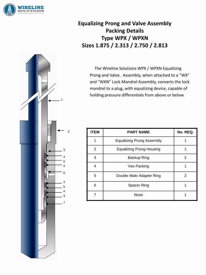
Equalizing Prong and Valve Assembly Packing Details
Type WPX / WPXN Sizes 1.875 / 2.313 / 2.750 / 2.813
The Wireline Solutions WPX / WPXN Equalizing
Prong and Valve. Assembly, when attached to a “WX”
and “WXN” Lock Mandrel Assembly, converts the lock
mandrel to a plug, with equalizing device, capable of
holding pressure differentials from above or below.
ITEM PART NAME No. REQ.
1 Equalizing Prong Assembly 1
2 Equalizing Prong Housing 1
3 Backup Ring 2
4 Vee Packing 1
5 Double Male Adapter Ring 2
6 Spacer Ring 1
7 Nose 1
1
3
4
5
4
6
4
5
4
3
7
2
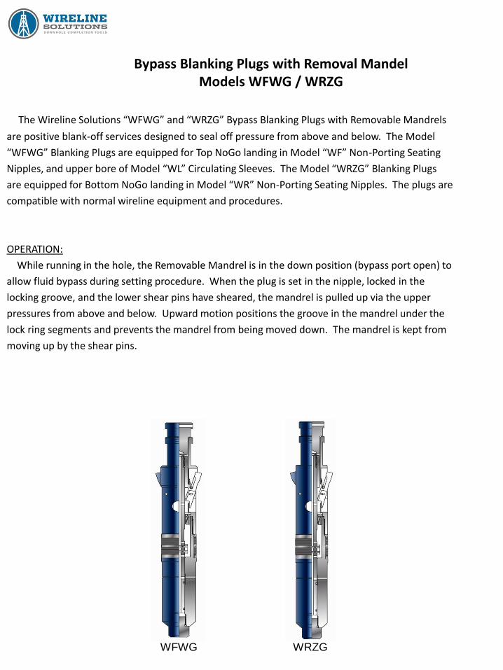
Bypass Blanking Plugs with Removal Mandel Models WFWG / WRZG
The Wireline Solutions “WFWG” and “WRZG” Bypass Blanking Plugs with Removable Mandrels
are positive blank-off services designed to seal off pressure from above and below. The Model
“WFWG” Blanking Plugs are equipped for Top NoGo landing in Model “WF” Non-Porting Seating
Nipples, and upper bore of Model “WL” Circulating Sleeves. The Model “WRZG” Blanking Plugs
are equipped for Bottom NoGo landing in Model “WR” Non-Porting Seating Nipples. The plugs are
compatible with normal wireline equipment and procedures.
OPERATION:
While running in the hole, the Removable Mandrel is in the down position (bypass port open) to
allow fluid bypass during setting procedure. When the plug is set in the nipple, locked in the
locking groove, and the lower shear pins have sheared, the mandrel is pulled up via the upper
pressures from above and below. Upward motion positions the groove in the mandrel under the
lock ring segments and prevents the mandrel from being moved down. The mandrel is kept from
moving up by the shear pins.
WFWG WRZG
Bypass Blanking Plugs with Removal Mandel Models WFWG / WRZG
Equalizing and Pulling Instructions
EQUALIZING (All plugs must be equalized before removing from hole)
1) Run in pulling tool and latch fishing neck of the removal mandrel.
2) Jar up to shear the pins on the removable mandrel and pull mandrel from hole.
NOTE: CAUTION! When the removable mandrel is out of the plug, the equalizing ports are open.
If pressure differential from below is high enough, the tool string may be blown
up hole unless precautions are taken.
PULLING MODELS WFWG AND WRZG
1) Run a Model B Probe on a standard pulling tool.
2) Jar down to drive the B Probe between the locks. This will retract them and at the same time
the pulling tool will latch onto the locking mandrel’s fishing neck permitting recovery of the
Bypass Blanking Plug.
CAUTION NOTE #1:
If any tool is to be landed on top of the plug or if the plug is to be tagged, care must be taken
not to run into the plug. If a tool of considerable weight has to be landed on the plug, then a
special guide that goes over the fishing neck and located on the lock mandrel will have to be
provided.
CAUTION NOTE #2:
It is possible, due to inertia when the fishing neck and mandrel are inverted, that these two
pieces could move a sufficient distance and make it impossible to pin the C-1 to the fishing
neck. If this happens, the Blanking Plug must be disassembled, the lock ring segments
removed, and the fishing neck pushed down into the proper positioning and pinning of the C-1
Running Tool. Insert the lock ring segment against the washer and finish redressing the tool.
NOTE #3:
A different fishing neck is used to run Models WFWG and WRZG tools with locks trailing or
collapsed.
Bypass Blanking Plugs with Removal Mandel Models WFWG / WRZG
Running and Setting Instructions
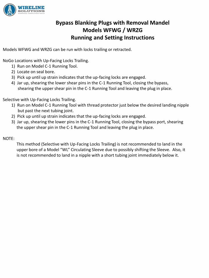
Models WFWG and WRZG can be run with locks trailing or retracted. NoGo Locations with Up-Facing Locks Trailing. 1) Run on Model C-1 Running Tool. 2) Locate on seal bore. 3) Pick up until up strain indicates that the up-facing locks are engaged. 4) Jar up, shearing the lower shear pins in the C-1 Running Tool, closing the bypass, shearing the upper shear pin in the C-1 Running Tool and leaving the plug in place. Selective with Up-Facing Locks Trailing. 1) Run on Model C-1 Running Tool with thread protector just below the desired landing nipple but past the next tubing joint. 2) Pick up until up strain indicates that the up-facing locks are engaged. 3) Jar up, shearing the lower pins in the C-1 Running Tool, closing the bypass port, shearing the upper shear pin in the C-1 Running Tool and leaving the plug in place. NOTE: This method (Selective with Up-Facing Locks Trailing) is not recommended to land in the upper bore of a Model “WL” Circulating Sleeve due to possibly shifting the Sleeve. Also, it is not recommended to land in a nipple with a short tubing joint immediately below it.
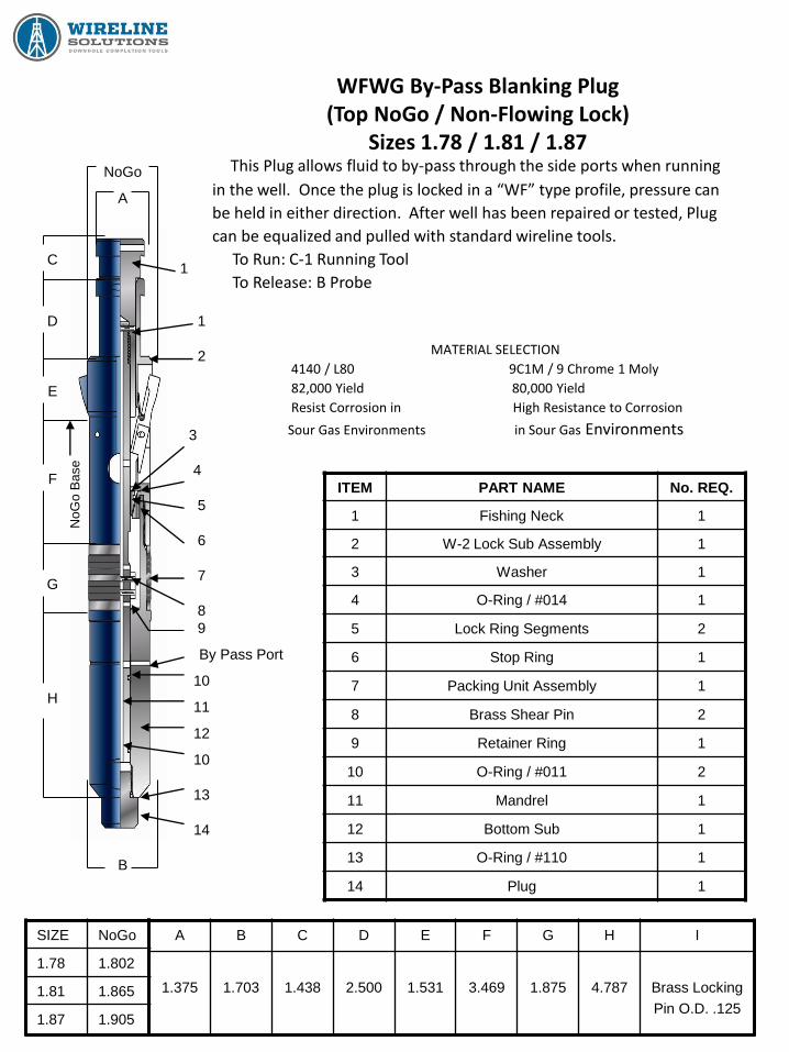
WFWG By-Pass Blanking Plug (Top NoGo / Non-Flowing Lock)
Sizes 1.78 / 1.81 / 1.87
This Plug allows fluid to by-pass through the side ports when running
in the well. Once the plug is locked in a “WF” type profile, pressure can
be held in either direction. After well has been repaired or tested, Plug
can be equalized and pulled with standard wireline tools.
To Run: C-1 Running Tool
To Release: B Probe
MATERIAL SELECTION
4140 / L80 9C1M / 9 Chrome 1 Moly
82,000 Yield 80,000 Yield
Resist Corrosion in High Resistance to Corrosion
Sour Gas Environments in Sour Gas Environments
ITEM PART NAME No. REQ.
1 Fishing Neck 1
2 W-2 Lock Sub Assembly 1
3 Washer 1
4 O-Ring / #014 1
5 Lock Ring Segments 2
6 Stop Ring 1
7 Packing Unit Assembly 1
8 Brass Shear Pin 2
9 Retainer Ring 1
10 O-Ring / #011 2
11 Mandrel 1
12 Bottom Sub 1
13 O-Ring / #110 1
14 Plug 1
SIZE NoGo
1.78 1.802
1.81 1.865
1.87 1.905
A B C D E F G H I
1.375
1.703
1.438
2.500
1.531
3.469
1.875
4.787
Brass Locking
Pin O.D. .125
NoGo
A
1
1
2
3
4
5
6
7
8
9
By Pass Port
10
11
12
10
13
14
B
C
D
E
F
G
H
NoG
o B
ase
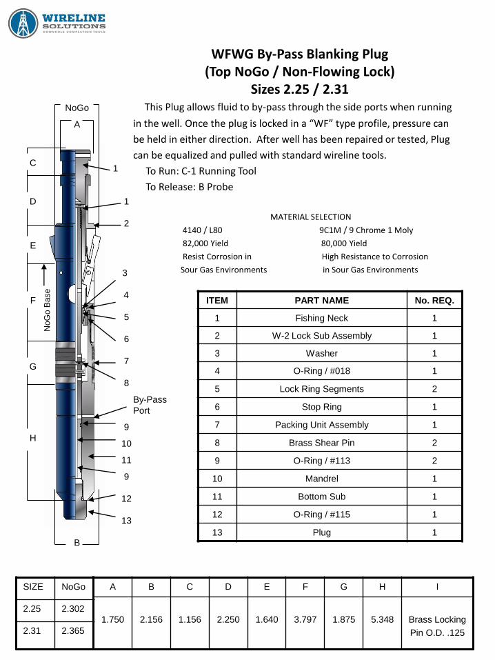
WFWG By-Pass Blanking Plug (Top NoGo / Non-Flowing Lock)
Sizes 2.25 / 2.31
This Plug allows fluid to by-pass through the side ports when running
in the well. Once the plug is locked in a “WF” type profile, pressure can
be held in either direction. After well has been repaired or tested, Plug
can be equalized and pulled with standard wireline tools.
To Run: C-1 Running Tool
To Release: B Probe
MATERIAL SELECTION
4140 / L80 9C1M / 9 Chrome 1 Moly
82,000 Yield 80,000 Yield
Resist Corrosion in High Resistance to Corrosion
Sour Gas Environments in Sour Gas Environments
ITEM PART NAME No. REQ.
1 Fishing Neck 1
2 W-2 Lock Sub Assembly 1
3 Washer 1
4 O-Ring / #018 1
5 Lock Ring Segments 2
6 Stop Ring 1
7 Packing Unit Assembly 1
8 Brass Shear Pin 2
9 O-Ring / #113 2
10 Mandrel 1
11 Bottom Sub 1
12 O-Ring / #115 1
13 Plug 1
SIZE NoGo
2.25 2.302
2.31 2.365
A B C D E F G H I
1.750
2.156
1.156
2.250
1.640
3.797
1.875
5.348
Brass Locking
Pin O.D. .125
NoGo
A
1
1
2
3
4
5
6
7
8
9
10
11
9
12
13
B
C
D
E
F
G
H
By-Pass
Port
NoG
o B
ase
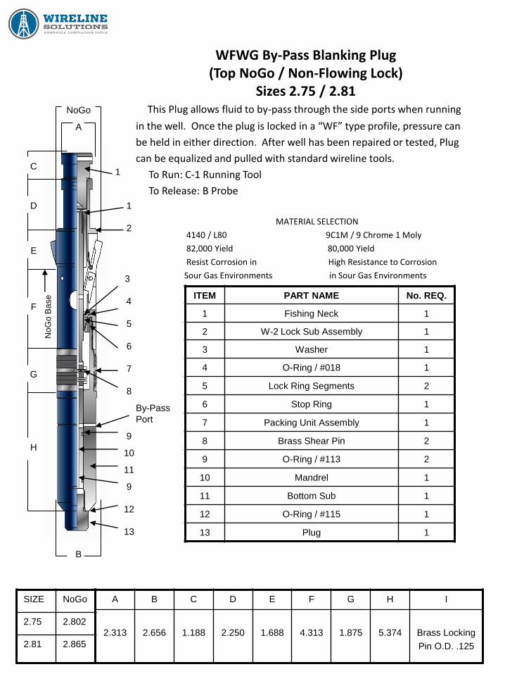
WFWG By-Pass Blanking Plug (Top NoGo / Non-Flowing Lock)
Sizes 2.75 / 2.81
This Plug allows fluid to by-pass through the side ports when running
in the well. Once the plug is locked in a “WF” type profile, pressure can
be held in either direction. After well has been repaired or tested, Plug
can be equalized and pulled with standard wireline tools.
To Run: C-1 Running Tool
To Release: B Probe
MATERIAL SELECTION
4140 / L80 9C1M / 9 Chrome 1 Moly
82,000 Yield 80,000 Yield
Resist Corrosion in High Resistance to Corrosion
Sour Gas Environments in Sour Gas Environments
ITEM PART NAME No. REQ.
1 Fishing Neck 1
2 W-2 Lock Sub Assembly 1
3 Washer 1
4 O-Ring / #018 1
5 Lock Ring Segments 2
6 Stop Ring 1
7 Packing Unit Assembly 1
8 Brass Shear Pin 2
9 O-Ring / #113 2
10 Mandrel 1
11 Bottom Sub 1
12 O-Ring / #115 1
13 Plug 1
SIZE NoGo
2.75 2.802
2.81 2.865
A B C D E F G H I
2.313
2.656
1.188
2.250
1.688
4.313
1.875
5.374
Brass Locking
Pin O.D. .125
NoGo
A
1
1
2
3
4
5
6
7
8
9
10
11
9
12
13
B
C
D
E
F
G
H
By-Pass
Port
NoG
o B
ase
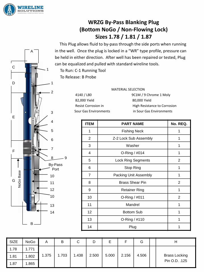
WRZG By-Pass Blanking Plug (Bottom NoGo / Non-Flowing Lock)
Sizes 1.78 / 1.81 / 1.87
This Plug allows fluid to by-pass through the side ports when running
in the well. Once the plug is locked in a “WR” type profile, pressure can
be held in either direction. After well has been repaired or tested, Plug
can be equalized and pulled with standard wireline tools.
To Run: C-1 Running Tool
To Release: B Probe
MATERIAL SELECTION
4140 / L80 9C1M / 9 Chrome 1 Moly
82,000 Yield 80,000 Yield
Resist Corrosion in High Resistance to Corrosion
Sour Gas Environments in Sour Gas Environments
ITEM PART NAME No. REQ.
1 Fishing Neck 1
2 Z-2 Lock Sub Assembly 1
3 Washer 1
4 O-Ring / #014 1
5 Lock Ring Segments 2
6 Stop Ring 1
7 Packing Unit Assembly 1
8 Brass Shear Pin 2
9 Retainer Ring 1
10 O-Ring / #011 2
11 Mandrel 1
12 Bottom Sub 1
13 O-Ring / #110 1
14 Plug 1
SIZE NoGo
1.78 1.771
1.81 1.802
1.87 1.865
A B C D E F G H
1.375
1.703
1.438
2.500
5.000
2.156
4.506
Brass Locking
Pin O.D. .125
A
1
1
2
3
4
5
6
7
8
10
11
12
10
13
14
B
C
D
E
F
G
By-Pass
Port
NoG
o B
ase
9

WRZG By-Pass Blanking Plug (Bottom NoGo / Non-Flowing Lock)
Sizes 2.25 / 2.31
This Plug allows fluid to by-pass through the side ports when running
in the well. Once the plug is locked in a “WR” type profile, pressure can
be held in either direction. After well has been repaired or tested, Plug
can be equalized and pulled with standard wireline tools.
To Run: C-1 Running Tool
To Release: B Probe
MATERIAL SELECTION
4140 / L80 9C1M / 9 Chrome 1 Moly
82,000 Yield 80,000 Yield
Resist Corrosion in High Resistance to Corrosion
Sour Gas Environments in Sour Gas Environments
ITEM PART NAME No. REQ.
1 Fishing Neck 1
2 Z-2 Lock Sub Assembly 1
3 Washer 1
4 O-Ring / #018 1
5 Lock Ring Segments 2
6 Stop Ring 1
7 Packing Unit Assembly 1
8 Brass Shear Pin 2
9 O-Ring / #113 2
10 Mandrel 1
11 Bottom Sub 1
12 O-Ring / #115 1
13 Plug 1
SIZE NoGo
2.25 2.240
2.31 2.302
A B C D E F G H
1.750
2.156
1.156
2.250
5.440
2.156
5.062
Brass Locking
Pin O.D. .125
A
1
1
2
3
4
5
6
7
8
9
11
10
9
13
C
D
E
F
G
B
By-Pass
Port
12
NoG
o B
ase
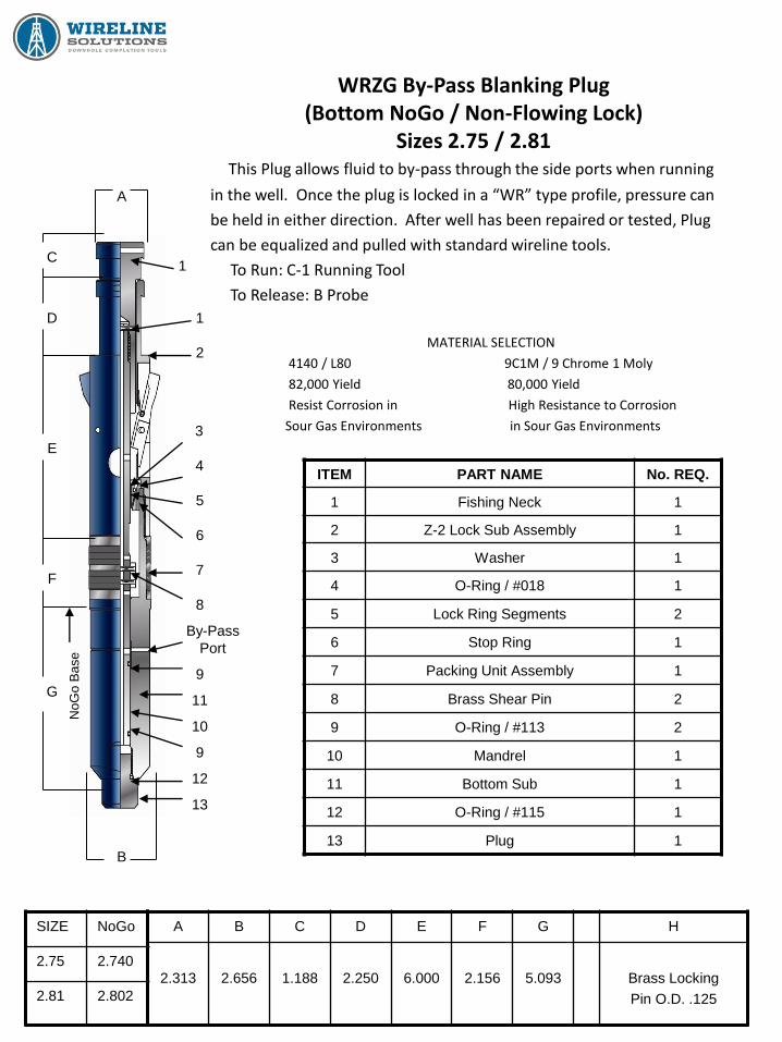
WRZG By-Pass Blanking Plug (Bottom NoGo / Non-Flowing Lock)
Sizes 2.75 / 2.81
This Plug allows fluid to by-pass through the side ports when running
in the well. Once the plug is locked in a “WR” type profile, pressure can
be held in either direction. After well has been repaired or tested, Plug
can be equalized and pulled with standard wireline tools.
To Run: C-1 Running Tool
To Release: B Probe
MATERIAL SELECTION
4140 / L80 9C1M / 9 Chrome 1 Moly
82,000 Yield 80,000 Yield
Resist Corrosion in High Resistance to Corrosion
Sour Gas Environments in Sour Gas Environments
ITEM PART NAME No. REQ.
1 Fishing Neck 1
2 Z-2 Lock Sub Assembly 1
3 Washer 1
4 O-Ring / #018 1
5 Lock Ring Segments 2
6 Stop Ring 1
7 Packing Unit Assembly 1
8 Brass Shear Pin 2
9 O-Ring / #113 2
10 Mandrel 1
11 Bottom Sub 1
12 O-Ring / #115 1
13 Plug 1
SIZE NoGo
2.75 2.740
2.81 2.802
A B C D E F G H
2.313
2.656
1.188
2.250
6.000
2.156
5.093
Brass Locking
Pin O.D. .125
A
1
1
2
3
4
5
6
7
8
9
10
11
12
13
C
D
E
F
G
B
9
By-Pass
Port
NoG
o B
ase