Fluidos II
23
Operation Where necessary, refer to the drawings in the Equipment Diagrams section. Operating the Equipment Positioning the F1-10 Hydraulics Bench The C4-Mkll is designed for use with the F1-10 Hydraulics Bench. The flume discharges into the horizontal channel that is moulded into the top of the F1-10. The F1-10 must therefore be positioned to allow water discharging from the flume to enter the top channel with minimal splashing. Water should enter the channel just beyond the Iip of the channel, without hitting the Iip, remaining clear of the end walI of the channel, as shown: As the flow rate and flume slope is altered, the angle of the water exiting the flume will change slightly. It may be necessary to move the F1-1O to allow for this, ensuring that the discharge flow always enters the channel. The F1-10 Hydraulics Bench is mounted on casters for ease of repositioning. Connecting the F1-10 Hydraulics Bench Disconnect any accessory that is already connected to the quick release connector on the F1-10 (connector Iocated inside the top moulded channel on the F1-10). Ensure that the F1-10 is switched off and the flow control valve ¡s closed then unscrew the quick release connector from the bed
-
Upload
sofiakaren -
Category
Documents
-
view
222 -
download
0
Transcript of Fluidos II

Operation
Where necessary, refer to the drawings in the Equipment Diagrams section.
Operating the Equipment
Positioning the F1-10 Hydraulics Bench
The C4-Mkll is designed for use with the F1-10 Hydraulics Bench. The flume discharges into the horizontal channel that is moulded into the top of the F1-10. The F1-10 must therefore be positioned to allow water discharging from the flume to enter the top channel with minimal splashing. Water should enter the channel just beyond the Iip of the channel, without hitting the Iip, remaining clear of the end walI of the channel, as shown:
As the flow rate and flume slope is altered, the angle of the water exiting the flume will change slightly. It may be necessary to move the F1-1O to allow for this, ensuring that the discharge flow always enters the channel. The F1-10 Hydraulics Bench is mounted on casters for ease of repositioning.
Connecting the F1-10 Hydraulics Bench
Disconnect any accessory that is already connected to the quick release connector on the F1-10 (connector Iocated inside the top moulded channel on the F1-10). Ensure that the F1-10 is switched off and the flow control valve ¡s closed then unscrew the quick release connector from the bed of the channel. Screw the adaptor, supplied with C4-Mkll, onto the threaded outlet in the bed of the channel then connect the f|€XIb|6 tube from the C4-Mkll to the union on top of the adaptor. The union incorporates a ‘O’ ring seal and only needs to be hand tight (do not use a tool to tighten the fitting).
To restore the F1-10 to normal use; unscrew the union to disconnect the flexible tube then unscrew the adaptor from the threaded outlet in the bed of the channel on F1-10. Screw the quick release connector onto the threaded outlet to allow the F1-10 to be used with any other accessories. It may be necessary to move the F1-10

slightly to the Ieft to allow operation with some accessories but the castors on the F 1-10 allow the unit to be easily repositioned.
Filling the F1-10 Hydraulics Bench with water
Place a filling hose ¡n the volumetric tank of the F1-10. Fill the sump tank with clean cold water by Iifting the dump valve in the base of the volumetric measuring tank and allowing the water to drain from the volumetric tank into the sump tank. (When lifted, a twist of 90° at the actuator will retain the dump valve in the open position.) When full ensure that the water level in the sump tank is just level with the outlet in the bottom of the volumetric tank.
A few drops of wetting agent (Teepol or similar) should be added to the water in the sump tank to reduce the effect of surface tension. Note that too much wetting agent will cause foaming.
Assembling and Installing Models
The bed-mounted models (with the exception of the Venturi flume, the false floor sections and the artificially roughened bed as described in later sections) are hooked in place via a retaining bar on the underside of the model using a clamping hook assembly. The rod incorporating the hook passes through a gland on the underside of the channel bed that incorporates a rubber ‘O’ ring seal to prevent water from leaking. Each gland should be adjusted so that the rod will move smoothly when pushed up or down but remain in position without leaking.
lf the rod does not slide smoothly through the gland then the ‘O’ ring seal inside the gland needs lubrication. To lubricate the ’O’ ring seals, unscrew the gland nuts on the underside of the bed then smear water soluble lubricant onto the seals before readjusting the tightness of the gland nuts. If water soluble lubricant is not available then a smear of wetting agent or liquid soap will suffice. The use of petroleum based grease or silicon lubricants is not recommended because these can contaminate the walls of the flume and the surface of the models affecting the surface tension of the water.
There are two hooks per 2.5 metre length of channel section. The diagrams below show how the model is retained in position. The

appropriate hook is pushed upwards to clear the channel bed. The required model is placed over the hook and then slid along until its retaining bar is beneath the hook. The hook is then pulled downwards from beneath to secure the model. The model will be held in place until the hook is pushed up again.
When not in use the model clamping rods can be inverted to minimise disturbance to the flow along the bed of the channel. To invert the rod unscrew the gland on the underside of the bed then pull the rod out from the gland from above. Re-insert the rod into the gland from below (taking care not to damage the ‘O’ ring in the gland) with the tip of the rod flush with the channel bed. Tighten the gland to retain the rod in position.
Assembling and Installing the Venturi Flume
The Venturi flume is held in place by a simple stretcher screw. This is placed between the two sections of the Venturi and adjusted to clamp them against the side walls of the channel.
Note: The stretcher must be placed above the level of the water so as not to interfere with the flow:
Installing the Optional False Floor Sections
The false floor sections are secured with the use of holes in the bed floor. The hooks are removed from the holes and pins are used instead. Each section of floor uses (two pins which push through the floor section and into the two holes in each working section (one section if 2.5 m, two sections if 5 m). The end ramps simply slot into the required end of the floor. The raised floor support is held in compression between the floor and the channel bed.
Installing the Optional Roughened Bed Sections
The artificially roughened (gravel) bed relies on its own weight to hold it onto the ' channel bed. It is aided by a bed end stop which is similar to the stretcher screw used on the Venturi flume except that it clamps between the channel side walls. This acts as a stop which prevents the gravel bed from sliding along the channel bed.
Sealing models into the flume

Some models incorporate flexible seals to minimize leakage during operation. Before installing the model in the working section, the seal should be wiped using soapy water to remove any contamination then lubricated with a smear of wetting agent or liquid soap to ease insertion into the flume. The use of petroleum based grease or silicon lubricants is not recommended because these can contaminate the walls of the flume and the surface of the models affecting the surface tension of the water.
Plasticine is supplied with the flumes for use where a seal is not incorporated on the model. This is used on the leading edge of the model and is placed between the side
When not in use the model clamping rods can be inverted to minimise disturbance to the flow along the bed of the channel. To invert the rod unscrew the gland on the underside of the bed then pull the rod out from the gland from above. Re-insert the rod into the gland from below (taking care not to damage the ‘O’ ring in the gland) with the tip of the rod flush with the channel bed. Tighten the gland to retain the rod in position.
Assembling and Installing the Venturi Flume
The Venturi flume is held in place by a simple stretcher screw. This is placed between the two sections of the Venturi and adjusted to clamp them against the side walls of the channel.
Note: The stretcher must be placed above the level of the water so as not to interfere with the flow:
I walls and bed of the channel and the sides of the model. This is to ensure that water flows over the model and not around or under it.
Use of Stop Logs to Vary Flume Flow Depth

The stop logs supplied slot into the discharge end of the channel. They may be used singly and in combination to raise the water level within the flume to different heights. Gaps between the logs may be sealed with Plasticine if required, but this is not usually necessary. .
Installing the Optional Pitot Tube and Manometer Board (C4-61)
The Pitot tube and manometer board is an optional accessory (Armfield order code C4-61) and is used in conjunction with the C4-Mkll Multi Purpose Teaching Flume to measure the local velocity of water flowing through the working section.
Partially fill the flume with water so that the head of the Pitot tube can be immersed when installed on the flume. The water in the flume should not be flowing during the priming procedure. .
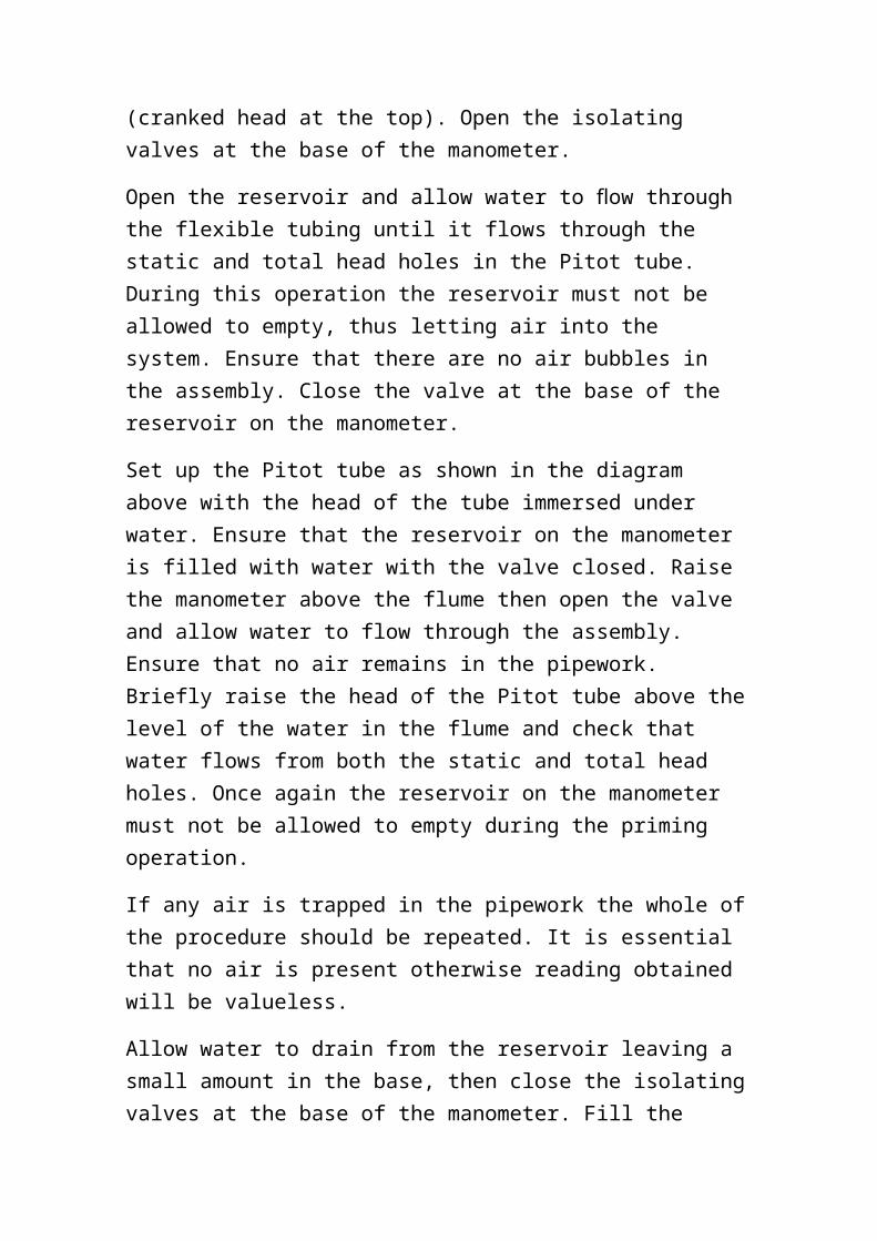
Before installing the Pitot tube and manometer on the flume it is necessary to prime them with water. Fill the manometer reservoir with water, ensuring that the valve at the base of the reservoir is closed. Position the manometer above the Pitot tube with the Pitot tube sloping uphill (cranked head at the top). Open the isolating valves at the base of the manometer.
Open the reservoir and allow water to flow through the flexible tubing until it flows through the static and total head holes in the Pitot tube. During this operation the reservoir must not be allowed to empty, thus letting air into the system. Ensure that there are no air bubbles in the assembly. Close the valve at the base of the reservoir on the manometer.
Set up the Pitot tube as shown in the diagram above with the head of the tube immersed under water. Ensure that the reservoir on the manometer is filled with water with the valve closed. Raise the

manometer above the flume then open the valve and allow water to flow through the assembly. Ensure that no air remains in the pipework. Briefly raise the head of the Pitot tube above the level of the water in the flume and check that water flows from both the static and total head holes. Once again the reservoir on the manometer must not be allowed to empty during the priming operation.
If any air is trapped in the pipework the whole of the procedure should be repeated. It is essential that no air is present otherwise reading obtained will be valueless.
Allow water to drain from the reservoir leaving a small amount in the base, then close the isolating valves at the base of the manometer. Fill the reservoir with paraffin (Kerosene, Specific Gravity = 0.784) then open each isolating valve in turn to half fill each manometer tube with paraffin. Take care to avoid slugs of paraffin/water in the fig manometer tubes. When both tubes are correctly filled to mid height close the isolating valve at the base of the reservoir.
Close the isolating valves at the base of the manometer until the equipment is ready for use.
Operating the Optional Pitot Tube and Manometer (C4-61)
The Pitot tube and manometer are used for measuring low velocities of water in the flume. If used with excessively high velocities, the paraffin will be pushed out of the manometer into the flexible tubing which may result in paraffin entering the flume.
DO NOT open the valve at the base of the reservoir during operation.
Open the flume inlet valve and allow water to flow slowly through the flume. Carefully open the isolating valves at the base of the manometer and note the difference in levels in the two limbs of the manometer.
The velocity of the water is calculated as follows:
For the Pitot tube

For the manometer
where:
Local velocity of water
Pitot tube coefficient (can be assumed to be unity)
For defining the position of the Pitot tube relative to the flume the following convention is used:
height above bed of flume (vertical level gauge)
These dimensions can be tabulated with the other results obtained.
This assembly can be used with many of the other accessories where velocities are required. The velocity profile in the flume can be obtained by moving the Pitot tube vertically and horizontally across the flume at different sections, noting the readings on the manometer at each position and converting these readings to a series of velocity profiles.
Installing the Optional Wave Generator (C4-67)
When required for use, the C4-67 Wave Generator should be mounted on top of the flow channel inlet tank with the vertical paddle at the entrance to the working section. The Wave Generator must be secured to the flange of the tank using the fixings supplied. Operation of the Wave Generator involves rotating and moving parts so extreme care must be taken when using the generator. Refer to the safety section of this instruction manual for specific notes regarding safe operation of the Wave Generator
The C4-67 Wave Generator consists of a vertical paddle that is moved backwards and forwards by a variable speed, variable stroke drive to produce water waves in the working section of the flow channel. The drive arrangement consists of a combined motor/gearbox with an eccentric crank wheel and connecting rod. The connecting rod can be connected to the crank wheel at different
radii to change the stroke of the paddle and thereby change the amplitude of the waves. The speed of the drive motor is continuously adjustable to change the frequency of the waves via the speed controller mounted on a bracket at the side.
The stop logs should be installed at the discharge end of the flume to retain the water inside the working section when the C4-67 Wave Generator is operating.
The triangular sloping beach, supplied with the C4-67 Wave Generator, should be installed inside the working section of the flow channel at the opposite end to the Wave Generator (located against the stop logs). This absorbs the energy of the waves to minimise the effect of reflected waves. The beach consists of a plastic strip with a 25 mm thick fibre mat bonded to it that allows water to flow through the material but resists the movement and absorbs the energy in the waves
Operating the Optional Wave Generator (C4-67) E
Changing the depth of the water
The depth of the water should be adjusted to suit the required demonstration. The water level should be raised by opening the flow control valve with the F1-10 Hydraulics Bench switched on. The water level should be lowered by opening the flow control valve with the F1-10 Hydraulics Bench switched off.
If the required depth of water is not known then the channel should be filled initially to mid height then tested by operating the wave paddle. The level can then be adjusted up or down to suit the demonstration. Note that insufficient water will give waves of small amplitude and excessive depth may result in water spilling from the sides of the channel when waves are generated.
Setting the required amplitude of the waves (stroke of the paddle)
Before making any adjustments to the stroke of the paddle the drive motor must be switched off at the control console and the electrical supply must be disconnected.

Having checked that the electrical supply is disconnected the guard can be removed from the drive arrangement by unscrewing the fixings.
The connecting rod can be attached to the crank wheel at different radii to give different stroke lengths. To change the stroke length simply unscrew the pin that attaches the connecting rod to the crank wheel using a suitable wrench then screw the pin into the appropriate tapped hole. Ensure that the pin securing the connecting rod is tight using a wrench.
The guard must be replaced before reconnecting the electrical supply and operating the paddle.
When operating the equipment for the first time it is suggested that the shortest stroke is selected. If larger amplitude of wave is required then the above procedure should be repeated moving the connecting rod to a larger radius on the crank wheel.
Setting the required frequency of the waves (speed of the drive motor)
Ensure that the guard is fitted to the drive arrangement and there are no obstructions to the movement of the paddle or connecting rod.
Check that the speed control knob is set to minimum (fully anticlockwise).
Turn on the on/off switch.
Gradually increase the speed of the motor by rotating the speed control knob clockwise until the required frequency of waves is achieved.
Warning: Excessive stroke, excessive frequency or overfilling of the flow channel may result in water spilling from the sides of the channel.
Typical demonstrations
Shallow water waves

The Wave Generator can be used to investigate the generation of regular water waves. As stated above, the depth of water, the amplitude of the waves and the frequency of the waves can be varied independently to suit the required demonstration.
Effectiveness of an energy absorbing beach
The sloping beach may be replaced with alternative structures or materials to suit the required demonstration. For example the effectiveness of a barrier constructed from small rocks could be investigated. Alternatively wedges of open cell foam with different density could be substituted to investigate the effectiveness of different types of foam.
Equipment Specifications
Overall Dimensions
C4-MKLII-2.5M only:
Height - 1.50m
Length - 3.4m
width - 0.62m
C4-MKII-5.0M only:
Height - 1.50m
Length - 5.41m
width - 0.62m
C4-MKII-2.5M with F1-10:
Height - 1.50m
Length - 3.66m
width – 0.90m
C4-MKII -5.0m with F1-10:
Height - 1.50m

Length - 611m
Width - 0.90m
Working Section Dimensions
Length of working section - 2.5m or 5.0m (as ordered)
Width of working section - 76mm
Depth of working section - 250mm L
Flume Slope
Max positive bed slope: +3.0%
Max negative bed slope: -1.0%
Flow Rate
Operating flow range: 0 - 1.6 litres/sec
Optional flowmeter range: 20 - 200 litres/min ±1% of FSD
Hook and Point Gauges (2 supplied)
Range of scale: 300 mm
Measurement accuracy: +/- 0.1 mm
Models Available for Use in the C4-Mkll Flume
The following accessories are supplied as standard with the C4-Mkll-2.5M and C4-Mkll-5.0M flumes:
Sharp crested weir
Broad crested weir
Adjustable undershot weir (sluice gate)
Crump weir
Venturi flume (2 sections to line the vertical walls of the channel)

The following accessories are available as an option for use with the C4-Mkll flume (all versions):
C4-61 Pitot tube and manometer board
C4-62 Culvert fitting, incorporates one square edge, one rounded edge
C4-63 Flow splitters, central wall with various nosepieces
C4-64 Free over flow spillway section, complete with ski jump, sloping apron and blended reverse curvature attachments
C4-65 Siphon spillway and air regulated siphon
C4-66 Model radial gate
C4-67 Wave generator and wave absorbing beach. Requires an electrical supply and therefore available in three versions:
C4-67-A 220/240 Volts, 1 Phase, 50 Hz
C4-67-B 120 Volts, 1 Phase, 60 Hz
C4-67-G 220/240 Volts, 1 Phase, 60 Hz
C4-68 False floor sections for gradually varied profiles, comprising: variable height laminated ramp, 2 parallel face sections with 2 end ramps and support piece to create raised false floor using 1 parallel face section
C4-69 Artificially roughened bed 2.5m long section (2 required for 5.0m flume).
Environmental Conditions
This equipment has been designed for operation in the following environmental conditions. Operation outside of these conditions may result reduced performance, it damage to the equipment or hazard to the operator.
a. Indoor use;
b. Altitude up to 2000 m

c. Temperature 5 “C to 40 °C;
d. Maximum relative humidity 80 % for temperatures up to 31 °C, decreasing linearly to 50 % relative humidity at 40 °C;
e. Mains supply voltage fluctuations up to ±10 % of the nominal voltage
f. Transient over-voltages typically present on the MAINS supply;
Note: The normal level of transient over-voltages is impulse withstand (over- ' r voltage) category ll of IEC 60364-4-443;
g. Pollution degree 2.
Normally only nonconductive pollution occurs.
Temporary conductivity caused by condensation is to be expected.
Typical of an office or laboratory environment.
Routine Maintenance
Responsibility
To preserve the life and efficient operation of the equipment it is important that the equipment is properly maintained. Regular maintenance of the equipment is the responsibility of the end user and must be performed by qualified personnel who understand the operation of the equipment.
General
The F1-10 should be disconnected from the electrical supply when not in use.
Water should be drained from the C4-Mkll when not in use.
All models should be removed from the flume when not in use. The models should be cleaned, dried and stored in a clean location to prevent contamination with dirt or grease.
Before re-installing a model in the working section, the seal should be wiped again using soapy water to remove any contamination then lubricated with a smear of wetting agent or liquid soap to ease insertion into the flume.
RCD test for F1-10 Hydraulics Bench
Test the RCD by pressing the TEST button at least once a month. If the RCD button does not trip when the Test button is pressed then the equipment must not be used and should be checked by a competent electrician.
Test condition of water in F1-10 Hydraulics Bench
Check that the water in the sump tank is clean and suitable for use. The water should be changed regularly to avoid stagnation (refer to the notes on the COSHH REGULATIONS at the front of this instruction manual). The use of a corrosion inhibitor which includes a biocide/disinfectant will reduce the formation of algae or micro-organisms and allow water changes to be performed less frequently. The frequency of water changes will depend on usage, local conditions and whether or not a biocide is used. As most corrosion inhibitors for the treatment of water are used in closed systems, ensure that the inhibitor/biocide used is safe to handle and does not create a hazard to the health of operators handling models immersed in the treated water.
If it is necessary to change the water, drain all water from the channel then open the drain cock on the underside of the F1-10 Hydraulics Bench and allow the water to drain. A flexible tube connected to the cock will allow the water to be directed to a suitable drain.
Refill the sump tank as described in the Operation section or Installation Guide of this instruction manual, using clean water and add the correct amount of an appropriate corrosion inhibitor with biocide if required (must be suitable for use with aluminium alloy). The sump tank contains approximately 250 litres of water. Refer to the details supplied with the inhibitor used for information on dilution.

Switch on the pump with the flow control valve closed, then gradually open the valve to circulate the water through the C4-Mkll channel and F1-10 to ensure that the a inhibitor has dispersed thoroughly and coated all wetted surfaces with a protective film.
Check C4-Mkll for leaks
The C4-Mkll channel, F1-10 Hydraulics Bench and interconnecting pipework should be checked visually for drips or staining associated with leaks. Any leaks identified should be attended to immediately to minimise deterioration of the equipment. Refer to Resealing for further information.
Check condition of channel bed
The surface of the aluminium bed inside the channel section is treated with chlorinated rubber paint (Oxford Blue B8105) to provide corrosion resistance. It is important that this finish is maintained in perfect condition to prevent corrosion of the bed.
Inspect the bed thoroughly for any sign of damage to, or deterioration of, the paint finish, such as scratches, discoloration, peeling, blistering etc. Care should be taken to look for small indentations through the paint surface caused by instruments such as the point of a hook and point gauge. Small areas of damage can be touched up locally provided that care is taken to remove all traces of corrosion before repainting. The frequency of repainting will depend on usage but repainting of the whole bed must be undertaken if any deterioration is located, however small. If repainting is necessary refer to Regainting the Channel Bed for further information.
Full Annual Service
It is important to carry out a full service at regular intervals, at least annually or more frequently according to usage and local conditions. The full service must include the following:
Note: As the channel will be out of use for several days while drained, cleaned, repainted etc. it is sensible to program the full service to coincide with an end of term shutdown etc.

Check for Leaks
Install the full set of stop logs at the discharge end of the channel. Operate the pump then open the flow control valve to fill the channel with water. Close the flow control valve then switch off the pump and allow the channel to stand for at least 24 hours. Check all joints, pipework etc. for leaks and mark any leaks for subsequent action.
Draining and cleaning
Having inspected for any leakage all water should be drained from the channel and sump tank.
The channel and F 1-10 Hydraulics Bench should be cleaned using warm water with household detergent then rinsed and dried. Particular attention should be paid to the clear acrylic walls of the channel if deposits are obscuring the view, taking care not to scratch the soft plastic. In order to restore visual clarity to scuffed, discoloured or surface crazed acrylic, an abrasive metal polish may be used.
After cleaning with warm soapy water, the painted bed should be checked for damage as described above. If repainting is necessary proceed as follows:
While the F 1-10 is drained the centrifugal pump can be checked. Refer to the leaflet supplied by the pump manufacturer for service details.