Float switch Replaces: 50214 - Bosch Rexroth
18
1/18 Information on available spare parts: www.boschrexroth.com/spc Float switches are switching devices operated by a float moved by fluid. They serve the control of filling levels in power unit tanks. Three series are available: Float switch Type ABZMS…M with a maximum of four ad- justable switching contacts normally closed / normally open or a maximum of three switching contacts and optionally fixed- ly set temperature contact as normally closed contact for 60 °C [140 °F], 70 °C [158 °F] or 80 °C [176 °F]. Float switch Type ABZMS...RTA with resistance measuring chain (level) and resistance thermometer (temperature) with analog output from 4 to 20 mA. Float switch Type ABZMS...D with resistance measuring chain and resistance thermometer as with Type ABZMS...RTA and additional display and control unit for level and tempera- ture setting. Content Page Features 1 Ordering code 2 Symbols, standard types 3 Technical data 4, 5 Mating connectors 6 Connection variants and pin assignment 6 … 8 Pre-set switching points Type M 8 Float switch with level and temperature contacts 9 Float switch with display and control unit 10 Function level, function temperature Function display and control unit 11 Oil volume specification for float switches 12, 13 Installation opening of the tank cover 14 Spare parts 15, 16 Assembly information, use in explosive areas according to directive 94/9/EC (ATEX), normative references 17 Type ABZMS-41 Component series 1X RE 50222/05.10 Replaces: 50214 Table of contents Features Float switch with switching contacts and temperature contact, with resistance measuring chain / resistance thermometer, with display and control unit HAD 7708/09
Transcript of Float switch Replaces: 50214 - Bosch Rexroth

1/18
Information on available spare parts:www.boschrexroth.com/spc
Float switches are switching devices operated by a float moved by fluid. They serve the control of filling levels in power unit tanks.Three series are available:Float switch Type ABZMS…M with a maximum of four ad-justable switching contacts normally closed / normally open or a maximum of three switching contacts and optionally fixed-ly set temperature contact as normally closed contact for 60 °C [140 °F], 70 °C [158 °F] or 80 °C [176 °F].Float switch Type ABZMS...RTA with resistance measuring chain (level) and resistance thermometer (temperature) with analog output from 4 to 20 mA.Float switch Type ABZMS...D with resistance measuring chain and resistance thermometer as with Type ABZMS...RTA and additional display and control unit for level and tempera-ture setting.
Content PageFeatures 1Ordering code 2Symbols, standard types 3Technical data 4, 5Mating connectors 6Connection variants and pin assignment 6 … 8Pre-set switching points Type M 8Float switch with level and temperature contacts 9Float switch with display and control unit 10Function level, function temperatureFunction display and control unit 11Oil volume specification for float switches 12, 13Installation opening of the tank cover 14Spare parts 15, 16Assembly information, use in explosive areas according to directive 94/9/EC (ATEX), normative references 17
Type ABZMS-41
Component series 1X
RE 50222/05.10Replaces: 50214
Table of contents Features
Float switchwith switching contacts and temperature contact, with resistance measuring chain / resistance thermometer, with display and control unit
HAD 7708/09
2/18 Bosch Rexroth AG Hydraulics ABZMS-41 RE 50222/05.10
Order example:– Float switch with flange port,
ordering length 370 mm [14.57 inch]– Two pre-set level contacts and temperature contact normally closed
at 70 °C [158 °F]– Connector K24ABZMS-S-41-1X/0370/M2-T70/DC-K24
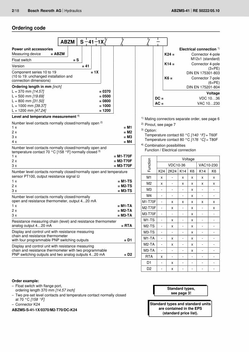
Ordering code
Standard types, see page 3!
Power unit accessoriesMeasuring device = ABZM
Float switch = S Version = 41Component series 10 to 19 = 1X(10 to 19: unchanged installation and connection dimensions)Ordering length in mm [inch]L = 370 mm [14.57] = 0370L = 500 mm [19.69] = 0500L = 800 mm [31.50] = 0800L = 1000 mm [39.37] = 1000L = 1200 mm [47.24] = 1200Level and temperature measurement 4)
Number level contacts normally closed/normally open 2)
1 x = M12 x = M23 x = M34 x = M4Number level contacts normally closed/normally open andtemperature contact 70 °C [158 °F] normally closed 3)
1 x = M1-T70F2 x = M2-T70F3 x = M3-T70FNumber level contacts normally closed/normally open and temperature sensor PT100, output resistance signal Ω1 x = M1-TS2 x = M2-TS3 x = M3-TSNumber level contacts normally closed/normallyopen and resistance thermometer, output 4...20 mA 1 x = M1-TA2 x = M2-TA3 x = M3-TAResistance measuring chain (level) and resistance thermometer analog output 4…20 mA = RTADisplay and control unit with resistance measuringchain and resistance thermometerwith four programmable PNP switching outputs = D1Display and control unit with resistance measuringchain and resistance thermometer with two programmable PNP switching outputs and two analog outputs 4...20 mA = D2
Electrical connection 1)
K24 = Connector 4-poleM12x1 (standard)
K14 = Connector 4-pole (3+PE)
DIN EN 175301-803K6 = Connector 7-pole
(6+PE)DIN EN 175201-804
VoltageDC = VDC 10…36AC = VAC 10…230
1) Mating connectors separate order, see page 62) Pinout, see page 73) Option:
Temperature contact 60 °C [140 °F] = T60FTemperature contact 80 °C [176 °C] = T80F
4) Combination possibilitiesFunction / Electrical connection
Func
tion Voltage
VDC10-36 VAC10-230K24 2K24 K14 K6 K14 K6
M1 x - x x x xM2 x - x x x xM3 - - - x - -M4 - - - x - -
M1-T70F - x x x x xM2-T70F - x - x - xM3-T70F - - - x - -M1-TS - x - x - -M2-TS - x - x - -M3-TS - - - x - -M1-TA - x - x - -M2-TA - x - x - -M3-TA - - - x - -RTA x - - - - -D1 - x - - - -D2 - x - - - -
Standard types and standard units are contained in the EPS
(standard price list).
ABZM S 41 1X

L1-..
L2-..
–Sx4-20mA
4-20mA
–SxL1-..
L2-..
T-..
4-20mA
4-20mA
Hydraulics Bosch Rexroth AGRE 50222/05.10 ABZMS-41 3/18
Symbols
with two switching contacts
with two switch-ing contacts and one temperature contact
with resistance mea-suring chain / resis-tance thermometer
with display and control unit, resistance measuring chain / resistance thermometer
Standard types and standard units arecontained in the EPS (standard price list).
Standard types
Ordering length L in mm [inch] Type Material number0370 [14.57] ABZMS-41-1X/0370/M2/DC-K24 R9012125880500 [19.69] ABZMS-41-1X/0500/M2/DC-K24 R901212589
Float switch with two switching contacts, Type ...M2...
Ordering length L in mm [inch] Type Material number0370 [14.57] ABZMS-41-1X/0370/M2-T70F/DC-K24 R9012125900500 [19.69] ABZMS-41-1X/0500/M2-T70F/DC-K24 R901212591
Float switch with two switching contacts and temperature contact, Type ...M2-TF70F...
Ordering length L in mm [inch] Type Material number0370 [14.57] ABZMS-41-1X/0370/RTA/DC-K24 R9012125920500 [19.69] ABZMS-41-1X/0500/RTA/DC-K24 R901212593
Float switch with resistance measuring chain and resistance thermometer, Type ...RTA...
Ordering length L in mm [inch] Type Material number0370 [14.57] ABZMS-41-1X/0370/D2/DC-K24 R9012125940500 [19.69] ABZMS-41-1X/0500/D2/DC-K24 R901212595
Float switch with display and control unit, resistance measuring chain and resistance thermometer, Type ...D2...

4/18 Bosch Rexroth AG Hydraulics ABZMS-41 RE 50222/05.10
Technical data (For applications outside these parameters, please consult us!)generalInstallation position Vertical ±10 °Medium temperature range °C [F] –20 to +80 [–4 to +176]Ambient temperature range
– M… and RTA °C [F] –20 to +85 [–4 to +185]– D1 and D2 °C [F] –20 to +70 [–4 to +158]
Material – Sliding tube Ø 20 mm [0.79 inch] CU alloy– Float 1.4571– Flange PA12 + 25GF (25 % of glass fiber)– Protective tube Ø 60.3 mm [2.37 inch] Stainless steel 1.4301
Seal material Klinger C-4400Maximum switching point L1 mm [inch] 1140 [44.88]Max. weight with ordering length mm
[inch]0370
[14.57]0500
[19.69]0800
[31.50]1000
[39.37]1200
[47.24]kg
[Ibs]0.5
[1.10]1.3
[2.87]1.8
[3.97]2.0
[4.41]2.2
[4.85]hydraulicMaximum operating pressure bar [psi] 1 [14.5] Hydraulic fluid
– Density g/cm3 > 0.8– Resistance
Resistant
• Mineral oils Mineral oil HLP according to DIN 51524
• Flame-resistant hydraulic fluids Emulsions HFA-E according to DIN 24320
Water solutions HFCaccording to VDMA 24317Phosphoric acid ester HFD-R
Organic esters HFD-U• Fast biodegradable hydraulic fluids Triglycerides (rape seed oil) HETG
according to VDMA 24568Synthetic esters HEES
Polyglycols HEPGelectricalProtection class according to DIN EN 60529 IP 65Plug-in connection 4-pole M12x1 (material: metal) (K24)
4-pole (3+PE) DIN EN175301-803 (K14)7-pole (6+PE) DIN EN175201-804 (K6)
Reed contacts of the float switches with connection K24, K14, K6/DCSwitching voltage range VDC 10 to 36 Max. switching current A 0.5Max. contact load VA 10
Temperature contacts of the float switches with connection K24, K14, K6/DCSwitching voltage range VDC 10 to 50 Max. switching current A 0.5Max. contact load VA 10Max. switching cycles 100.000Response tolerance K ±3 with max. 1k/min.Hysteresis K up to 10 with max. 1k/min.Max. temperature change velocity K/min. 1

Hydraulics Bosch Rexroth AGRE 50222/05.10 ABZMS-41 5/18
PT100Sensor element PT100 class B; DIN EN 60751Temperature measuring range °C [°F] 0 to 100 [32 to 212]Accuracy K ±0.8
Resistance measuring chain and resistance thermometer with connection K24 for mating connector M12x1; 4-pole Operating voltage VDC 10 to 36 Signal output mA 4 to 20
(alternatively 0 to 10, 2 to 10 or 0 to 5 V can be set)Resolution resistance measuring chain mm 5Max. load Ω (U – 9.0 V) / 0.02 AMeasuring range temperature °C [°F] 0 to 100 [32 to 212]
Technical data (For applications outside these parameters, please consult us!)
Display and control unitSupply voltage VDC 10 to 32Display range °C [°F] –20 to +120 [–4 to +248]Alarm adjustment range:
– Temperature °C [°F] 0 to 100 [32 to 212]– Level % / liter [US gal] 0 to 100 / 0 to 999 [263.91]
Switching points 4 programmable switching outputs (2 level + 2 temperature)
Housing design PA, IP65 (antistatic)Display 4 digits, seven-segment LED displayCurrent consumption upon switch-on ca. 100 mA for 100 msCurrent consumption in operation ca. 50 mA with UB 24 VSwitching output PNP, max. 0.5 A switching powerMax. ambient temperature °C [°F] –20 to +70 [–4 to +158]Accuracy 1 % of the measurement range end valueOperation 3 buttons
Reed contacts of the float switches with connection K14 according to DIN EN 175301-803 / K6 according to DIN EN 175201-804/ACSwitching voltage range VDC/VAC 10 to 230 Max. switching current A 0.5Max. contact load VA 10Temperature contacts of the float switches with connection K14 according to DIN EN 175301-803 / K6 according to DIN EN 175201-804/ACSwitching voltage range VDC/VAC 10 to 230 Max. switching current A 2.5Max. contact load VA 100Max. switching cycles 100.000Response tolerance K ±3 with max. 1k/min.Hysteresis K up to 10 with max. 1k/min.Max. temperature change velocity K/min. 1

54
M12
x1
Ø19
,6
[2.13]
[0.
77]
M12
x 1
41,5 [1.63]
6/18 Bosch Rexroth AG Hydraulics ABZMS-41 RE 50222/05.10
Mating connectors (dimensions in mm [inch]) – For detailed information see RE 08006
Mating connector for connector K14 according to DIN EN 175301-803
53
34,2
1
M16 x 1,5
[2.09]
[1.3
5]
Mating connector for connector K6 according to DIN EN 175201-804
Mating connector for connector K24
Description Material no.MATING CONNECTOR 4P Z14 M SW SPEZ R901017012
Description Material no.MATING CONNECTOR 7P Z6 N6RFFK R900002803
Description Material no.MATING CONNECTOR 4P Z24 SPEZ R900031155
1 fastening screw M3, tightening torque MA = 0.5 Nm
Mating connector for connector K24 with potted-in PVC cable, 3 m long
Description Material no.MATING CONNECTOR 4P Z24M12X1 +3MSPEZ R900064381
Connection variants and pin assignment
Connector type K24 Version M with 1 or 2 level contacts
Version M with 1 x level contact + temperature contact
Version RTA with level output 4-20 mA
+ temperature output 4-20 mA
423
1L2
L1
L1423
1L1 1 4
3
2TK
M12x1
4-20mA
4-20mA
+24 V DC 14-20 mA 4level
4-20 mA 2level
level
Pt100
Hydraulics Bosch Rexroth AGRE 50222/05.10 ABZMS-41 7/18
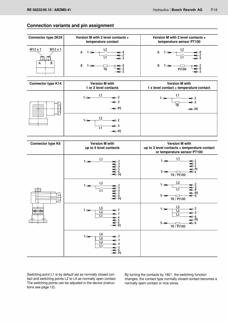
Connection variants and pin assignment
Connector type 2K24 Version M with 2 level contacts + temperature contact
Version M with 2 level contacts + temperature sensor PT100
M12 x 1 M12 x 1
A B
A 1
B 1
423
423
TK
L2
L1A 1
B 1
423
243
Pt100
L2
L1
Connector type K14 Version M with 1 or 2 level contacts
Version M with 1 x level contact + temperature contact
1 23
PE
L11 2
3
PETK
L1
1 2
3
PE
L2
L1
Connector type K6 Version M with up to 4 level contacts
Version M with up to 3 level contacts + temperature contact
or temperature sensor PT100
1 23456PE
L1 1
5
234PE6
TK / Pt100
L1
1 23456PE
L2
L1
1
5
234PE6
L2
L1
TK / Pt100
1 23456PE
L3
L1L2
1
5
234PE6
L3
L1L2
TK / Pt100
1 23456PE
L4
L1L2L3
Switching point L1 is by default set as normally closed con-tact and switching points L2 to L4 as normally open contact. The switching points can be adjusted in the device (instruc-tions see page 12).
By turning the contacts by 180°, the switching function changes; the contact type normally closed contact becomes a normally open contact or vice versa.
8/18 Bosch Rexroth AG Hydraulics ABZMS-41 RE 50222/05.10
+24 V 1
4-20 mA 2
4-20 mA 4
GND 3
1 +24 V
2 OUT2
4 OUT1
3 GND
Pt100
BA
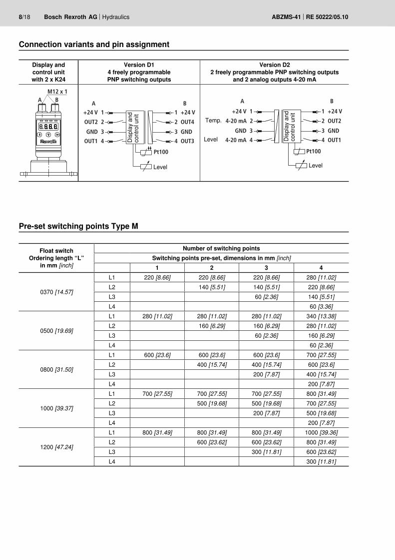
Display and control unit with 2 x K24
Version D1 4 freely programmable PNP switching outputs
Version D2 2 freely programmable PNP switching outputs
and 2 analog outputs 4-20 mA
A BM12 x 1
B
+24 V 1
OUT2 2
OUT1 4
GND 3
1 +24 V
2 OUT4
4 OUT3
3 GND
Pt100
A
Connection variants and pin assignment
Float switch Ordering length “L”
in mm [inch]
Number of switching pointsSwitching points pre-set, dimensions in mm [inch]
1 2 3 4
0370 [14.57]
L1 220 [8.66] 220 [8.66] 220 [8.66] 280 [11.02]L2 140 [5.51] 140 [5.51] 220 [8.66]L3 60 [2.36] 140 [5.51]L4 60 [3.36]
0500 [19.69]
L1 280 [11.02] 280 [11.02] 280 [11.02] 340 [13.38]L2 160 [6.29] 160 [6.29] 280 [11.02]L3 60 [2.36] 160 [6.29]L4 60 [2.36]
0800 [31.50]
L1 600 [23.6] 600 [23.6] 600 [23.6] 700 [27.55]L2 400 [15.74] 400 [15.74] 600 [23.6]L3 200 [7.87] 400 [15.74]L4 200 [7.87]
1000 [39.37]
L1 700 [27.55] 700 [27.55] 700 [27.55] 800 [31.49]L2 500 [19.68] 500 [19.68] 700 [27.55]L3 200 [7.87] 500 [19.68]L4 200 [7.87]
1200 [47.24]
L1 800 [31.49] 800 [31.49] 800 [31.49] 1000 [39.36]L2 600 [23.62] 600 [23.62] 800 [31.49]L3 300 [11.81] 600 [23.62]L4 300 [11.81]
Pre-set switching points Type M
Disp
lay
and
cont
rol u
nit
Level
Disp
lay
and
cont
rol u
nit
Level
Level
Temp.
Ø 9
0[Ø
3.5
4]
Ø 7
3[Ø
2.8
7]
Ø 6
[Ø 0
.24]
5
32
4
7
6
1
8
1 [0
.04]
5 [0
.20]
L1
3,5
[0.1
4]
Ø 51[Ø 2.01]
Ø 20 [Ø 0.79]
L
Ø 60,3[Ø 2.37]
36 [1
.42]
43 [1
.69]
60 [2
.36]
M12x1
L
L2
(57
[2.2
4])
min
. 40
[min
. 1.5
7]
57 [2
.24]
60 [2
.36]
43 [1
.69]
M12x1M12x1
M12x12K24K24
K6K14
A B
Hydraulics Bosch Rexroth AGRE 50222/05.10 ABZMS-41 9/18
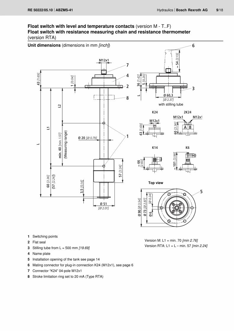
Float switch with level and temperature contacts (version M - T..F)Float switch with resistance measuring chain and resistance thermometer(version RTA)Unit dimensions (dimensions in mm [inch])
1 Switching points2 Flat seal3 Stilling tube from L = 500 mm [19.69]4 Name plate5 Installation opening of the tank see page 146 Mating connector for plug-in connection K24 (M12x1), see page 67 Connector “K24” 04-pole M12x18 Stroke limitation ring set to 20 mA (Type RTA)
Top view
with stilling tube
(Mea
surin
g ra
nge)
Version M: L1 = min. 70 [min 2.76]Version RTA: L1 = L – min. 57 [min 2.24]
2
1
6
7
4
3
5
9
M12x1
12 [
0.47
]
121
[4.7
6]
1 [0
.04]
10
5 [0
.20]
Ø90
[Ø
3.54
]
Ø73
[Ø
2.87
]
Ø6
[Ø0.
24]
L2 =
25
[0.9
8]
L1
L
57 [
2.24
]
3,5
[0.1
4]
57 [
2.24
]
Ø51[Ø2.01]
Ø20 [Ø0.79]
L
Ø60,3[Ø2.37]
A B
8
10/18 Bosch Rexroth AG Hydraulics ABZMS-41 RE 50222/05.10
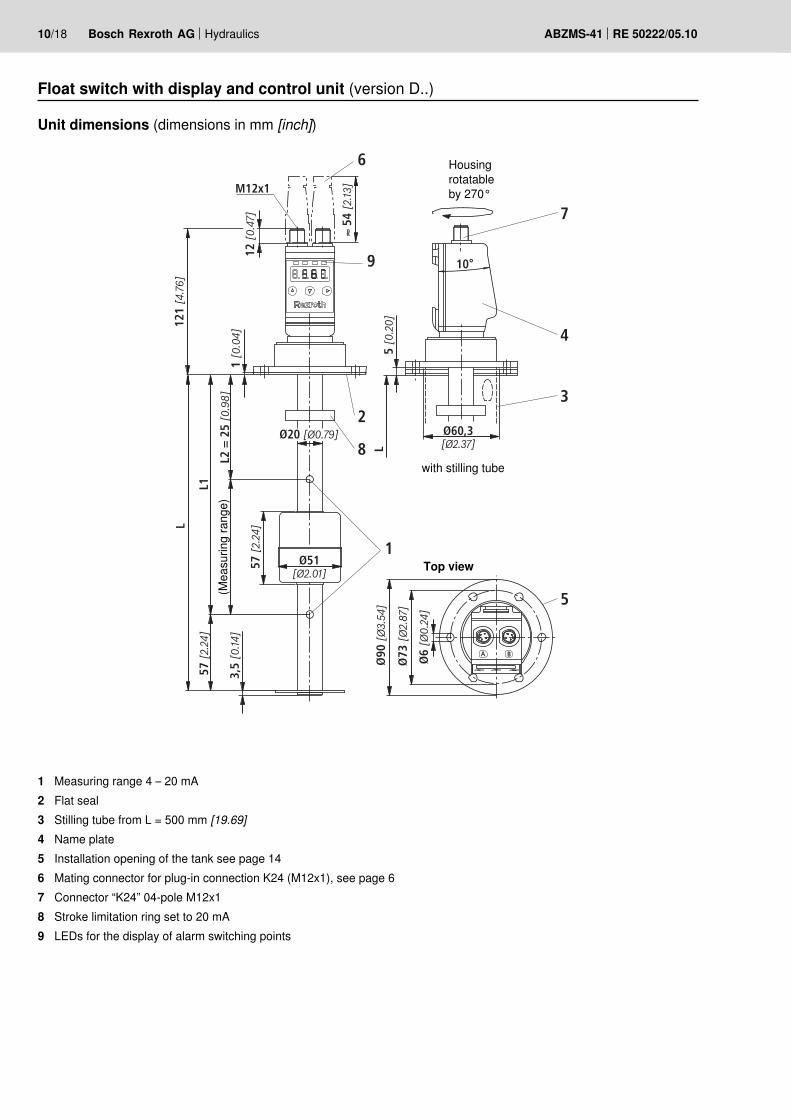
Float switch with display and control unit (version D..)
Unit dimensions (dimensions in mm [inch])
1 Measuring range 4 – 20 mA2 Flat seal3 Stilling tube from L = 500 mm [19.69]4 Name plate5 Installation opening of the tank see page 146 Mating connector for plug-in connection K24 (M12x1), see page 67 Connector “K24” 04-pole M12x18 Stroke limitation ring set to 20 mA9 LEDs for the display of alarm switching points
Top view
with stilling tube
Housing rotatable by 270°
(Mea
surin
g ra
nge)

Hydraulics Bosch Rexroth AGRE 50222/05.10 ABZMS-41 11/18
Level contacts:The sliding tubes contain the adjustable reed contacts (nor-mally closed and normally open) that are switched by the per-manent magnets installed in the float.If with falling oil level, the float reaches the switching points, the contacts are operated magnetically. The spool positions of the contacts are maintained until the float exceeds the switching points again as the oil level rises.The switching points can be adjusted in the device.
The microprocessor-controlled display and control unit pro-cesses the analog input signals for the analysis of the level and temperature control. The level and temperature settings can be made at the control unit in a simple menu tree by means of pushbuttons and read at the LED display. The display and control unit has a red, four-digit seven-segment LED display and 3 pushbuttons for the operation as well as up to 4 LEDs integrated in the front plate for display-ing alarm conditions.The device has moreover four freely adjustable PNP switch-ing outputs plus the adjustable switch-back points (version D1) and alternatively (version D2) two freely programmable PNP switching outputs and 2 x 4-20 mA output for the contin-uous measurement of oil level and temperature. The switching conditions are shown in the display. The 4-20 mA output can optionally be changed to 0-10 V, 2-10 V or 0-5 V. In the display, the measured temperature or filling value will be shown in the desired unit (°C, °F, L, cm, %, inch or mm) according to the setting. By default, the temperature display is set to °C. During the setting and/or programming of the corresponding process parameters, the parameter values and/or the related menu items will be shown in the display.In case of an energy supply failure, all input values will be stored, the min/max values can be retrieved from a perma-nent memory, if necessary.
Function level
Function display and control unit (version D)
By turning the contacts by 180°, the switching function changes; the contact type normally closed contact becomes a normally open contact or vice versa.
Resistance measuring chain:The sliding tube contains the resistance measuring chain (contact distance 5 mm / resolution) for the continuous re-cording of the filling level. If the individual reed contact is switched (closed) by the permanent magnet contained in the float, one resistance is in each case activated. The added re-sistance value is converted in 4-20 mA by a transformer.
Temperature contact:At the lowest point within the sliding tube, the bi-metal tem-perature contacts are attached to the board and secured by means of a shrink tube (the same procedure is used for the versions with temperature sensor PT 100 and resistance ther-mometer with analog output 4-20 mA). If the desired tempera-ture switching point is reached, the bi-metal contact is opened or closed.
Function temperature Temperature sensor PT100:The PT100 consists of a temperature sensor guaranteeing continuous temperature recording. In this connection, the max. cable length of 6 m [236.22] is to be observed.
Resistance thermometer with measuring transducer, output 4–20 mA:The resistance thermometer PT100 with measuring transduc-er is also attached in the sliding tube at the board. The tem-perature-dependent signal is converted into a linear current change of 4-20 mA.
Parameterization The menu navigation is based on the VDMA standard sheet for fluid sensors 24574-1.The operating menu is designed hierarchically, as tree struc-ture.That means that frequently used functions and adjustment points can be accessed very quickly and rarely used menu items can be found in a sub-menu.Using the ▲ and ▼ keys, the corresponding parameter is set and/or the next menu item is displayed.Using the ► key, the marked menu item is selected and/or the set parameter is accepted and saved.The parameter may be a numerical value and a selection of functions (e.g. NO [output as normally open contact], NC [output as normally closed contact] or i1 [analog output 4…20 mA]).After confirmation of a parameter or selection of a function us-ing the ► key, the display switches back to the current menu item. Then, you can display the next menu item using ▲ and ▼ and select it using ►.

L2
L1
max.
1
min.
2
12/18 Bosch Rexroth AG Hydraulics ABZMS-41 RE 50222/05.10
Oil volume specification for float switch (dimensions in mm [inch])
Type M with two switching contacts
1 Residual quantity with switching point L1 1)
2 Residual quantity with switching point L2 1)
Float switchOrdering length “L”
in mm [inch]
Switching pointpre-set Residual hydraulic fluid volume at switching point
Dimensions in mm [inch] AB 40-40, AB 40-43, AB 40-44L1 L2 Size L1 1) in liter [US gal] L2 1) in liter [US gal]
220 [8.66] 140 [5.51]
63 28 [7.40] 42 [11.10]100 45 [11.89] 67 [17.70]160 74 [19.55] 100 [26.42]
370 [14.57] 250 120 [31.70] 174 [45.97]400 190 [50.19] 277 [73.18]630 365 [96.42] 475 [125.48]800 460 [121.52] 600 [158.50]
500 [19.69] 280 [11.02] 160 [6.30]
1000 490 [129.44] 740 [195.49]1250 780 [206.05] 1030 [272.10]1600 990 [261.53] 1310 [346.07]2000 1380 [364.56] 1730 [457.02]
Attention!Before commissioning, the switching contacts are to be set according to the necessary operating conditions.
Adjustment of the switching heightThe contacts installed in the float switch are screwed to a contract strip within the sliding tube. They are set to the switching points according to the preceding table and can be adjusted upwards or downwards retroactively (observe minimum distanc-es!). Proceeds as follows in order to adjust the contacts:– Interrupt the voltage supply– Loosen the plug-in connections– Loosen the screws of the plug-in connector base and pull out the plug-in connector base with the contact strip– Loosen the contact from the strip and mount it at the requested spot (can be adjusted in 10 mm increments)– Insert the contact strip smoothly– Fasten the plug-in connector base using screws– Re-establish the plug-in connection and the power connection

7637
0[1
4.57
]
max.
min.
30
200
mm
100
mA20
14
16
18
12
10
8
6
4
97
70
80
90
60
50
40
30
2015
160
130140150
1201101009080
25304050607031
0[1
2.20
]
30[1
.81]
55[2
.17]
[2.9
9]
249
150
100
50
393
350
200
79
150
100
200
250
300
630600
225
350
300
500
450
550
400
250
800
700
285
350
600
500
650
750
400
550
450
DN
100
DN
160
DN
250
DN
400
DN
630
DN
800
250
150
310
76
500
[19.
69]
min.
mm mA
440
[17.
32]
30[1
.81]
131[
5.16
][2
.99]
1010 1655
500
400
2110
1900
11201200
1700
1500
1800
2000
1300
1600
1400
DN
1000
DN
1250
DN
1600
DN
2000
7655
[2.1
7][2
.99]
1100
1200
1500
1300
1600
1400
755800
900
1000
1100
1200
1300
700
800
900
1000
595
700
800
900
600
14
16
4
6
8
10
400
12
18
20
300
250
100
30
200
350
440
350
Hydraulics Bosch Rexroth AGRE 50222/05.10 ABZMS-41 13/18
Oil volume specification for float switch (dimensions in mm [inch])
Type RTA, D1 and D2In tank according to AB 40-40, AB 40-43 and AB 40-44
Liter
Mea
surin
g ra
nge
Liter
Mea
surin
g ra
nge
Tank size from DN100 to 800
Tank size from DN1000 to 2000

6 x
M5
[2.44+0.04]
[2.87–0.008]
14/18 Bosch Rexroth AG Hydraulics ABZMS-41 RE 50222/05.10
Installation opening of the tank cover (dimensions in mm [inch])
Standard breakthrough AB 03-39.73 similar to DIN 24557 part 2Fastening screws:6 HEXAGON SOCKET HEAD CAP SCREWS ISO4762-M5X18-8.8-A2P Material no. R900202612
1 3 A2
Hydraulics Bosch Rexroth AGRE 50222/05.10 ABZMS-41 15/18
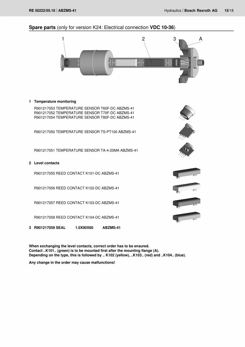
Spare parts (only for version K24: Electrical connection VDC 10-36)
1 Temperature monitoringR901217053 TEMPERATURE SENSOR T60F-DC ABZMS-41 R901217052 TEMPERATURE SENSOR T70F-DC ABZMS-41R901217054 TEMPERATURE SENSOR T80F-DC ABZMS-41
R901217050 TEMPERATURE SENSOR TS-PT100 ABZMS-41
R901217051 TEMPERATURE SENSOR TA-4-20MA ABZMS-41
2 Level contacts
R901217055 REED CONTACT K101-DC ABZMS-41
R901217056 REED CONTACT K102-DC ABZMS-41
R901217057 REED CONTACT K103-DC ABZMS-41
R901217058 REED CONTACT K104-DC ABZMS-41
3 R901217059 SEAL 1.0X90X60 ABZMS-41
When exchanging the level contacts, correct order has to be ensured. Contact ..K101.. (green) is to be mounted first after the mounting flange (A). Depending on the type, this is followed by .. K102 (yellow), ..K103.. (red) and ..K104.. (blue).
Any change in the order may cause malfunctions!

16/18 Bosch Rexroth AG Hydraulics ABZMS-41 RE 50222/05.10
1 3 A2
Spare parts (only for version K14 and K6: Electrical connection VDC 10-230)
1 Temperature monitoring
R901270930 TEMPERATURE SENSOR T60F-AC ABZMS-41 R901270931 TEMPERATURE SENSOR T70F-AC ABZMS-41R901270932 TEMPERATURE SENSOR T80F-AC ABZMS-41
2 Level contacts
R901270933 REED CONTACT K231-AC ABZMS-41
R901270934 REED CONTACT K232-AC ABZMS-41
3 R901217059 SEAL 1.0X90X60 ABZMS-41
When exchanging the level contacts, correct order has to be ensured. Contact ..K231.. (purple) is to be mounted first and ..K232.. (brown) second after the mounting flange (A).
Any change in the order may cause malfunctions!
Hydraulics Bosch Rexroth AGRE 50222/05.10 ABZMS-41 17/18
Assembly information– Vertical installation according to technical data page 4– Avoid flows– Do not expose the switch to strong impact and bends– Avoid external magnetic fields. They may impair the func-
tion of the reed contacts.
Use in explosive areas according to directive 94/9/EC (ATEX)The float switches ABZMS-41 are not suitable for the use in explosive areas.
Normative references
AB 24-02Cable sets and distributors
AB 40-40Tanks made of steel, form AN, cover form C,oil pan according to WHG
AB 40-43Tanks made of steel, cover form C
AB 40-44Tanks made of steel, with frame
RE 08006Mating connectors for controlling electrically operated valves and sensors
DIN 24320Flame-resistant fluids – Hydraulic fluids of categories HFAE and HFAS – Properties and requirements
DIN 51524Hydraulic fluids; hydraulic oils
DIN EN 175201-804: Detail specification – Circular connec-tors – Round contacts, size diameter 1.6 mm; threaded cou-pling; German version EN 175201-804:1999
DIN EN 175301-803: Detail specification: Rectangular con-nectors – Flat contacts, 0.8 mm thickness, locking screw not detachable; German version EN 175301-803:1999
DIN EN 60751Industrial platinum resistance thermometers and platinum temperature sensors (IEC 60751:2008)
DIN EN 60529Degrees of protection provided by enclosures
VDMA 24317Fluid technology – Flame-resistant fluids – Technical mini-mum requirements
VDMA 24568Fluid technology – Fast biodegradable hydraulic fluids – Tech-nical minimum requirements
VDMA 24574-1Fluid technology – Terms, menu navigation and electrical connection for fluid sensors
Electrical connections:– Electrical connections may only be performed by specialists– Before performing any works at electrical parts, the voltage
supply is to be interrupted– Tighten round connector M12x1 or mating connectors
after connection– Only plug in the round connector M12x1 or mating connec-
tor if it is de-energized– Do not overload the contacts (see technical data)– In case of inductive load, provide for a protective
circuit!

Bosch Rexroth AGHydraulicsZum Eisengießer 197816 Lohr am Main, GermanyPhone +49 (0) 93 52 / 18-0Fax +49 (0) 93 52 / 18-23 [email protected]
© This document, as well as the data, specifications and other informa-tion set forth in it, are the exclusive property of Bosch Rexroth AG. It may not be reproduced or given to third parties without its consent.The data specified above only serve to describe the product. No state-ments concerning a certain condition or suitability for a certain applica-tion can be derived from our information. The information given does not release the user from the obligation of own judgment and verification. It must be remembered that our products are subject to a natural process of wear and aging.
18/18 Bosch Rexroth AG Hydraulics ABZMS-41 RE 50222/05.10
Notes