Rexroth IndraDrive - Bosch Rexroth · Rexroth IndraDrive - Bosch Rexroth

Operating instructions
RE 50222-B/03.12Replaces: -English
Float switchType ABZMS-41
The data specified above only serve to describe the product. No statements concerning a certain condition or suitability for a certain application can be derived from our information. The information given does not release the user from the obligation of own judgment and verification. It must be remembered that our products are subject to a natural process of wear and aging.
© This document, as well as the data, specifications and other information set forth in it, are the exclusive property of Bosch Rexroth AG. It may not be reproduced or given to third parties without its consent.
The cover page shows an example configuration. The product supplied may therefore differ from the photo shown.
The original operating instructions were prepared in German.

RE 50222-B/03.12 | Type ABZMS-41 Bosch Rexroth AG 3/40
Content1 Introduction .....................................................................................................4
1.1 Configuration.............................................................................................41.2 Field of application ....................................................................................4
2 Important notes ...............................................................................................53 Assembly and connection .............................................................................6
3.1 Tank installation ........................................................................................63.2 Connection variants and pinout ................................................................73.3 Voltage supply variants .............................................................................83.4 Adjustment of the switching point positioning for Mx models....................93.5 Adjustment of the switching points' switching function for Mx models ....103.6 Notes on the service life extension of reed contacts...............................10
4 Operation .......................................................................................................114.1 Switch-on ................................................................................................114.2 LED status displays ................................................................................114.3 General key functions ............................................................................124.4 Active key lock .......................................................................................134.5 Menu overview ........................................................................................134.6 Changing the basic settings ....................................................................144.7 Switching outputs ....................................................................................214.8 Analog outputs ........................................................................................274.9 Diagnosis possibilities .............................................................................29
5 Maintenance ..................................................................................................325.1 Inspection and maintenance ...................................................................325.2 Service and repair ...................................................................................325.3 Troubleshooting ......................................................................................32
6 Disposal .........................................................................................................327 Technical data ...............................................................................................338 Appendix: Overview menu sequence .........................................................35

4/40 Bosch Rexroth AG Type ABZMS-41 | RE 50222-B/03.12
Introduction
Introduction1 Read the operating instructions carefully before using the device. Particularly observe the notes in chapter 2. Otherwise, injuries or damage to property may result. Bosch Rexroth AG will not accept any liability for unauthorized changes in the device or for improper use.
Configuration1.1 The sensors of the ABZMS41 series serve the monitoring of the filling level and/or the temperature in fluid systems, if applicable. From pure switches to the continu-ous filling level and temperature measurement and/or indication, this specification comprises all options.The following models are available:
ABZMS... float switchM1 to M4 1 to 4 level contacts, normally closed or normally open contactM1-T70F to M3-T70F 1 to 3 level contacts, normally closed or normally open and
temperature contact 70 °C, normally closed contact (option 60/80 °C)
M1-TS to M3-TS 1 to 3 level contacts, normally closed or normally open contact and Pt 100 temperature sensor
M1-TA to M3-TA 1 to 3 level contacts, normally closed or normally open contact and resistance thermometer output 4 to 20 mA
RTA Resistance measuring chain (level) and resistance thermom-eter; analog output 4 to 20 mA
D1 Display and control unit with resistance measuring chain, resistance thermometer and four programmable PNP switching outputs
D2 Display and control unit with resistance measuring chain, resistance thermometer and two programmable PNP switch-ing outputs and two analog outputs 4 to 20 mA (analog output programmable in 0-10 V, 2-10 V, 0-5 V) Two PNP outputs can be assigned as frequency output.
Field of application1.2
Float switch types are no safety components. Use in explosive areas or in case of danger due to malfunction may impair safety and health.
Don't use the float switch if in case of failure or in case of malfunction, the fsafety and health of persons might be impaired.Don't use the float switch in explosive areas. f
WARnInG!

RE 50222-B/03.12 | Type ABZMS-41 Bosch Rexroth AG 5/40
Content
Important notes2 Please check before installing the device whether the specified technical data cor-responds to the application parameters. Also check whether all parts belonging to the scope of delivery are completely available.Use of the devices is only admissible if:
The product is used under the conditions described in the operating instruc- •tions, the use according to name plate and for applications for which it is intended. In case of unauthorized changes in the device, liability by Bosch Rexroth AG is excluded.The limits specified in the data sheet and the instructions are complied with. •Monitoring equipment / protective equipment has been connected correctly. •The service and repair works not described in these instructions are carried out •by Bosch Rexroth AG.Original spare parts are used. •
These operating instructions are part of the operating equipment. The manufac-turer reserves the right to change the performance, specification or the design data without advance notice. Keep the instructions for later use.In these instructions, the following warning signs and signal words are used:
Warning sign Warning
Warning of the inhalation of noxious gases
Warning of corrosive fluids
Warning of explosive areas
Signal word ApplicationnOTE! Signal word for important information on the product, to which particu-
lar attention is to be drawn.
CAuTIOn! Signal word for marking a hazard with little risk, which can lead to damage to property or minor to medium bodily injuries unless it is avoided.
WARnInG! Signal word for marking a hazard with medium risk, which will possibly lead to death or serious bodily injuries unless it is avoided.
DAnGER! Signal word for marking a hazard with high risk, which will directly lead to death or serious bodily injuries unless it is avoided.
The device may only be installed by specialists who are familiar with the safety requirements and the risks. You must imperatively observe the safety regulations relevant to the place of installation as well as the generally valid rules of current technology. Prevent failures and thus prevent personal injuries and damage to property.

6/40 Bosch Rexroth AG Type ABZMS-41 | RE 50222-B/03.12
Assembly and connection
The person responsible for the system must ensure that:Safety instructions and operating instructions are available and complied with, •Accident prevention regulations of the Accident Prevention & Insurance •Association are complied with; in Germany: BGV A1: Prevention principles and BGV A3: Electrical systems and work equipment,The admissible data and operating conditions are complied with, •Protective devices are used and prescribed maintenance works are carried out, •In the disposal, the legal regulations are complied with. •
Repairs at the operating equipment may only be carried out by personnel authorized by Bosch Rexroth.
Only carry out modification, maintenance or assembly works described in these •operating instructions.Only use original spare parts. •When carrying out maintenance works of any kind, the relevant safety and •operating provisions have to be observed.
Assembly and connection3
Tank installation3.1 Assembly and connection may only be performed by correspondingly trained specialists. The applicable safety regulations of the place of installation are to be complied with!
Danger of poisoning!Poisonous, corrosive gases or fluids may cause serious injuries.
Protect yourself from poisonous, corrosive gases / fluids during all works. fAlways wear inhalation protection, face protection and gloves. f
Risk of explosion!Risk of serious injuries due to explosions.
Don't use the float switch in explosive areas. f
For direct tank attachment, the switching tube is screwed into the intended bore (according to DIN 24557, part 2) with the GI cork seal at the tank. The mounting is realized using the enclosed screws and seals at the DIN flange. In this connec-tion, it must be ensured that the float is freely moveable and that the distance to the tank wall and installations is sufficient. After a possible disassembly of the float, it has to be made sure that the solenoid in the float is above the fluid level. The easiest way to check this is by means of an iron part by means of which you determine the position of the solenoid in the float. The voltage supply is effected using the connectors.
Maintenance, repair
DAnGER!
DAnGER!

RE 50222-B/03.12 | Type ABZMS-41 Bosch Rexroth AG 7/40
Assembly and connection
Connection variants and pinout3.2
Plug-in connector type K24 Version M1 and/or 2 level contacts
Version M1 level contact
+ temperature contact
Version RTALevel output 4-20 mA
+ temperature output 4-20 mA
423
1L1
2TK
43
1L1
423
1L2
L1
Plug-in connector type 2K24 2 level contacts + temperature contact
2 level contacts + temperature sensor PT 100
2 level contacts +resistance thermometer
4 3
1 TK
4 2 3
1 L2 L1
2 B
A
4 3
1 Pt 100
4 2 3
1 L2 L1 A
B
43
1
423
1 L2 L1
A
B 4-20mA
Plug-in connector type K14 Version M1 and/or 2 level contacts
Version M1 level contact + temperature contact
3PE
1L1
TK3PE
1L1
3PE
1L2
L1
Plug-in connector type K6 Version Mup to 4 level contacts
Version Mup to 3 level contacts +
temperature contact / Pt 100
Version Mup to 3 level contacts +resistance thermometer
3
4
5
6
PE
1L1
3
4
1
5
L1
TK / Pt 1006
PE
3
4
5
6
PE
1L2
L1
5
3
4
1L2
L1
TK / Pt 1006
PE
5
3
4
1L2
L1
4-20mA6
PE
L2
L13
4
5
6
PE
1L3
5
L2
L13
4
1L3
TK / Pt 1006
PE
L3
L2
L1
3
4
5
6
PE
1L4

8/40 Bosch Rexroth AG Type ABZMS-41 | RE 50222-B/03.12
Assembly and connection
Voltage supply variants3.3 Function Voltage
VDC 10-36 VAC 10-230K24 2K24 K14 K6 K14 K6
M1 X - X X X XM2 X - X X X XM3 - - - X - -M4 - - - X - -
M1-T70F - X X X X XM2-T70F - X - X - XM3-T70F - - - X - -M1-TS - X - X - -M2-TS - X - X - -M3-TS - - - X - -M1-TA - X - X - -M2-TA - X - X - -M3-TA - - - X - -RTA X - - -D1 - X - -D2 - X - -
Display and control unit with 2 x K24
Version D14 programmable PnP switching outputs
Version D22 programmable PnP switching outputs
+ 2 programmable analog outputsM12x1
A B

RE 50222-B/03.12 | Type ABZMS-41 Bosch Rexroth AG 9/40
Assembly and connection
Adjustment of the switching point positioning for 3.4 Mx models
The contacts operated by the float are fastened to a galvanically gold-plated contact strip (with cm scale) by means of plastic screws. The contact housings are color-coded any may only be mounted on the contact strip in the given order. They are positioned according to the order data ex works and can be adjusted upwards or downwards retroactively (observe minimum distances!).In models with continuous level output (RTA), no changes can be made. They are fixedly set ex works (analog output: 4 mA = tank empty; 20 mA = tank full).
For positioning the switching points, proceed as follows:
Interrupt the voltage supply! fLoosen the plug-in connections. fScrew off the plug-in connector base and carefully pull it out upwards together fwith the adapter plug and the contact strip.Loosen the plastic screws at the contacts and re-position the contacts using fthe cm scale (it is located on the back side of the contact strip). They can be adjusted in 1 cm steps.In order to fasten the contacts, tighten the plastic screws manually. fEnsure during the assembly that the adapter plug is re-applied to the contact fstrip in the correct way. This can be seen from the red mark at the adapter plug and the contact strip.

10/40 Bosch Rexroth AG Type ABZMS-41 | RE 50222-B/03.12
Assembly and connection
Adjustment of the switching points' switching 3.5 function for Mx models
The contacts are designed as normally open (NO) or normally closed (NC) contact, depending on the order. As the contacts are bistable, any subsequent change in the contact function is possible by rotating the contacts by 180°. On the contact housing, there are two arrows. The arrow pointing upwards in the installed condition indicates the valid contact function (see following example).
Any information with sinking oil level.
notes on the service life extension of reed contacts3.6 Due to their construction, reed contacts are very durable and reliable compo-nents. Nevertheless, the following should be observed:Contact protectionExcessive inductive loads creating high inverse voltages when a reed switch is opened can be reduced by means of the following circuit.
A) Direct voltage (DC): protective diode parallel to the load
A)
B) Alternating voltage (AC): RC element parallel to the load and according to the following table.
B)
VA 10 25 50 75 100Voltage at the open contact R/Ohm C/µF R/Ohm C/µF R/Ohm C/µF R/Ohm C/µF R/Ohm C/µF
24 AC 22 0.022 1 0.1 1 0.47 1 1.0 1 1.048 AC 120 0.0047 22 0.022 1 0.1 1 0.47 1 0.47115 AC 470 0.001 120 0.0047 22 0.022 22 0.047 22 0.1230 AC 470 0.001 470 0.001 120 0.0047 120 0.022 120 0.022

RE 50222-B/03.12 | Type ABZMS-41 Bosch Rexroth AG 11/40
Operation
Operation4 The models without indication and control unit are immediately ready for opera-tion after connection of the supply voltage. In the following, the operation of the models with display and control unit is described.
Switch-on4.1 If during ongoing operation, an error message appears in the display, please observe chapter 5.3 "Troubleshooting".After the device has been connected to the supply voltage, the software version will be shown shortly in the beginning. Directly afterwards, the display changes to the measured value display.
In the following, the function of the display and control unit is described.
LED status displays4.2 Light-emitting diodes above the measured value display signal the status of the switching outputs. The LEDs are fixedly assigned to the switching outputs. The following table shows the factory settings for the assignment of the switching outputs to filling level and temperature.
The LEDs' switching behavior (illuminated in case of closed or open switching contact) can be changed; in this connection see chapter 4.7.7.
2 switching outputs 4 switching outputsLED 1 – yellow Assigned: Switching output 1
Filling level Filling level
LED 2 - red Assigned: Switching output 2
Temperature Filling level
LED 3 - yellow Assigned: Switching output 3
--- Temperature
LED 4 - red Assigned: Switching output 4
--- Temperature
12/40 Bosch Rexroth AG Type ABZMS-41 | RE 50222-B/03.12
Operation
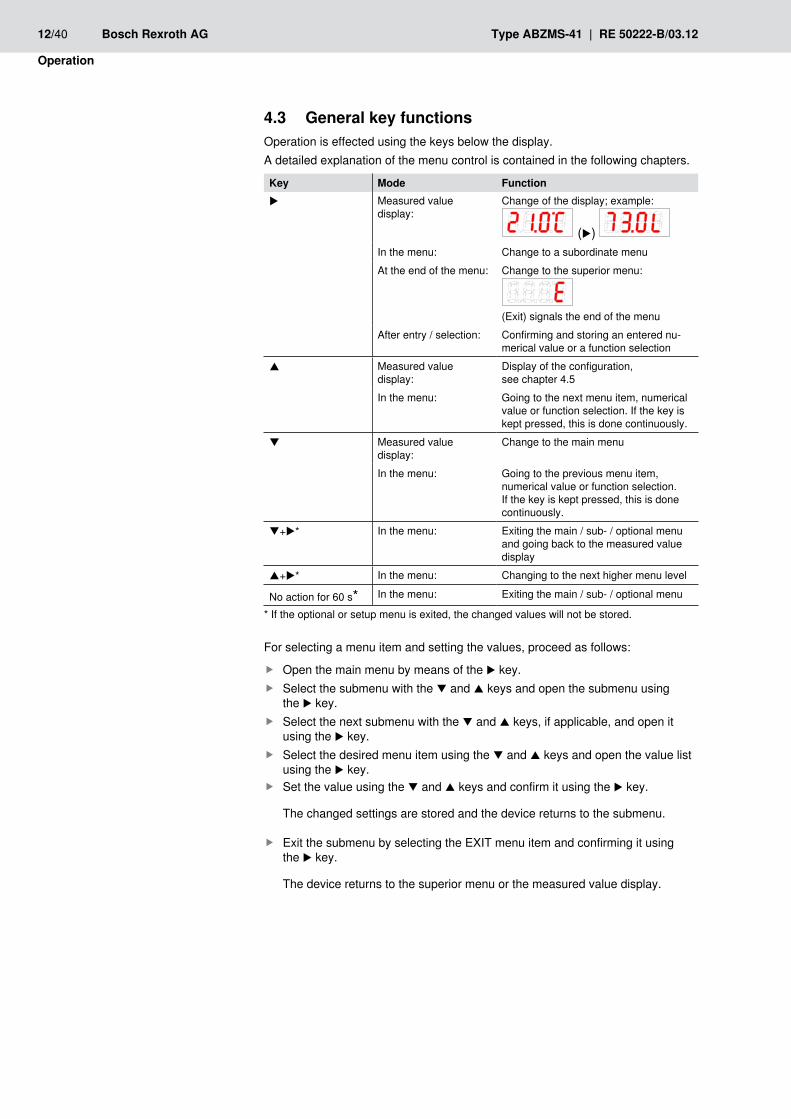
General key functions 4.3 Operation is effected using the keys below the display.A detailed explanation of the menu control is contained in the following chapters.
Key Mode Functionu Measured value
display:Change of the display; example:
(u)
In the menu: Change to a subordinate menuAt the end of the menu: Change to the superior menu:
(Exit) signals the end of the menu
After entry / selection: Confirming and storing an entered nu-merical value or a function selection
p Measured value display:
Display of the configuration, see chapter 4.5
In the menu: Going to the next menu item, numerical value or function selection. If the key is kept pressed, this is done continuously.
q Measured value display:
Change to the main menu
In the menu: Going to the previous menu item, numerical value or function selection. If the key is kept pressed, this is done continuously.
q+u* In the menu: Exiting the main / sub- / optional menu and going back to the measured value display
p+u* In the menu: Changing to the next higher menu level
No action for 60 s* In the menu: Exiting the main / sub- / optional menu
* If the optional or setup menu is exited, the changed values will not be stored.
For selecting a menu item and setting the values, proceed as follows:
Open the main menu by means of the f u key.Select the submenu with the f q and p keys and open the submenu using the u key.Select the next submenu with the f q and p keys, if applicable, and open it using the u key.Select the desired menu item using the f q and p keys and open the value list using the u key.Set the value using the f q and p keys and confirm it using the u key.
The changed settings are stored and the device returns to the submenu.
Exit the submenu by selecting the EXIT menu item and confirming it using fthe u key.
The device returns to the superior menu or the measured value display.
RE 50222-B/03.12 | Type ABZMS-41 Bosch Rexroth AG 13/40
Operation
Active key lock 4.4 When the key lock is activated, the following display will appear instead of the
main menu when calling the menu using the q key:
The active number is marked by a point.
Enter the code using the f q and p keys and confirm it using the u key.
The active number is moved one digit to the right. After entry of the 3rd number, the main menu opens.
If a wrong numerical code is entered, the device jumps back to the measured value display. If you have forgotten the password, you can access the menu at any time by means of the master code 287.You can cancel the key lock by resetting the code with the entry 000 in the Loc menu item in the "Basic ext. functions" b.EF submenu.
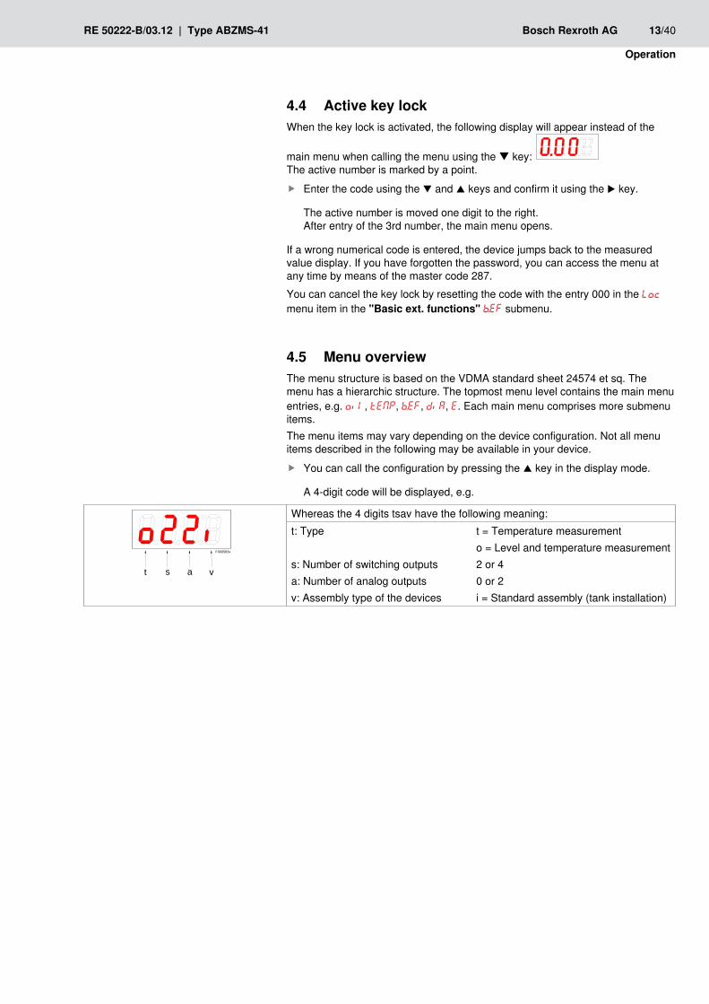
Menu overview4.5 The menu structure is based on the VDMA standard sheet 24574 et sq. The menu has a hierarchic structure. The topmost menu level contains the main menu entries, e.g. oil, tEMP, b.EF, diA, E. Each main menu comprises more submenu items.The menu items may vary depending on the device configuration. Not all menu items described in the following may be available in your device.
You can call the configuration by pressing the f p key in the display mode.
A 4-digit code will be displayed, e.g.
t s a v
F000583x
Whereas the 4 digits tsav have the following meaning:t: Type
s: Number of switching outputsa: Number of analog outputsv: Assembly type of the devices
t = Temperature measuremento = Level and temperature measurement2 or 40 or 2i = Standard assembly (tank installation)

14/40 Bosch Rexroth AG Type ABZMS-41 | RE 50222-B/03.12
Operation
Changing the basic settings4.6 In the "Basic ext. functions" (b.EF) menu, the generally valid basic settings are made. These settings influence the presentation in the measured value display as well as the setting options in the "Level" and "Temperature" menus. Assignment of the switching outputs to the filling level and/or temperature measurement (if available) can be changed here.
In order to access the main menu, press the f q key.Select the f b.EF menu item using the q and p keys and open the menu using the u key.
The individual menu items will not appear if the option is not available. Example: With a = 0, the menu items for setting the analog output are not available. You can then skip the description of these points.The structure of the main menu "Level" (oil) and "Temper-ature" (tEMP) is identical. Here, the settings for the switching outputs and/or the analog outputs (if available) are made. The basic settings oft he device can be changed. Generally valid settings are made in the "Basic ext. functions" (b.EF) menu. These settings should be made first as they influence the displays and setting possibilities in the individual menus. Such settings include e.g. the units used and the assign-ment of the switching outputs to filling level and temperature measurement. The assignment of the analog outputs cannot be changed. In addition, diagnosis possibilities are available in the "Diag-nostic" menu.For the detailed presentation of the entire menu structure please refer to the end of these instructions.
RE 50222-B/03.12 | Type ABZMS-41 Bosch Rexroth AG 15/40
Operation
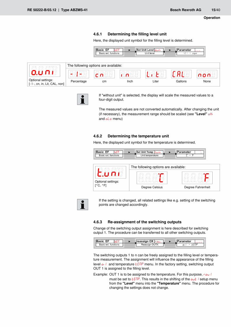
Determining the filling level unit4.6.1 Here, the displayed unit symbol for the filling level is determined.
If "without unit" is selected, the display will scale the measured values to a four-digit output.
The measured values are not converted automatically. After changing the unit (if necessary), the measurement range should be scaled (see "Level" o.Hi and o.Lo menu)
Determining the temperature unit4.6.2 Here, the displayed unit symbol for the temperature is determined.
Optional settings:[°C, °F]
The following options are available:
Degree Celsius
Degree Fahrenheit
If the setting is changed, all related settings like e.g. setting of the switching points are changed accordingly.
Re-assignment of the switching outputs 4.6.3 Change of the switching output assignment is here described for switching output 1. The procedure can be transferred to all other switching outputs.
The switching outputs 1 to n can be freely assigned to the filling level or tempera-ture measurement. The assignment will influence the appearance of the filling level oil and temperature tEMP menu. In the factory setting, switching output OUT 1 is assigned to the filling level.Example: OUT 1 is to be assigned to the temperature. For this purpose, r.ou1 must be set to tEMP. This results in the shifting of the out1 setup menu from the "Level" menu into the "Temperature" menu. The procedure for changing the settings does not change.
Optional settings:[- I -, cn, in, Lit, CAL, non]
The following options are available:
Percentage
cm
Inch
Liter
Gallons
None

16/40 Bosch Rexroth AG Type ABZMS-41 | RE 50222-B/03.12
Operation
In the re-assignment of the switching outputs, all related settings have to be checked! The values set in advance are not adjusted automatically! The assignment of the LEDs to the status display does not change.
The following options are available:
Filling level measurement
Temperature measurement
Assignment of the other switching outputs to the filling level or temperature mea-surement is realized in the same way as for switching output 1.
Perform the same steps as described for the switching output OUT 1. f
Setting the display's update rate4.6.4 Depending on the application, the display's update rate can be set. The display can also be switched off completely.
Error messages will be displayed despite switched-off display.
Activating / deactivating the key lock4.6.5 In order to prevent unauthorized changes in the device settings, a key lock can be setup.
The key lock is activated if at least one number > 0 is entered. During the entry, the active number is marked with a point.
The following options are available:
Fast (FASt)
Medium (MEdi)
Slow (slow, SLo)
Display off (oFF)

RE 50222-B/03.12 | Type ABZMS-41 Bosch Rexroth AG 17/40
Operation
Setting range: 000 to 999
Open the value list by means of the f u key:
Set the figure using the f q and p keys (0 to 9) and confirm it using the u key.
The active number is moved one digit to the right.
Finally confirm the code by means of the f u key.
The device returns to the submenu.
Canceling the key lock with the entry: 000

18/40 Bosch Rexroth AG Type ABZMS-41 | RE 50222-B/03.12
Operation
Filling level scaling4.6.6 The display range is scaled between the highest and the lowest point of the float. The display accuracy and the resolution for the determination of the switching outputs for the filling level are also influenced by this scaling.The factory setting of the switching points and the display is shown in the follow-ing figure:
Models with analog output:The display increases when the filling level increases so that at the lowest point possible, 0 % and with the highest point possible 100 % are displayed. These values can be changed as described below.
Models without analog output:As the installation situation is not known in the factory, the distance of the float to the flange level in cm is shown as pre-setting. As with a falling filling level, this results in a greater value, this is relativized by putting a minus sign in front of the display value. In a level switch with a length of 370 mm, the value rises e.g. from –31.5 (cm) to –2.5 (cm) when the level rises. These values can be changed as described below.

RE 50222-B/03.12 | Type ABZMS-41 Bosch Rexroth AG 19/40
Operation
Filling level: Maximum display value4.6.7 Here, the largest display value (upper limit of the measurement range) for the maximum filling level is determined.
Setting range:–999…9999
Assignment of the largest display value (upper limit of the measurement range) to the maximum filling level.
In order to avoid malfunctions, the settings of the level outputs should be checked and/or adjusted after any change in the value.
Filling level: Minimum display value4.6.8 Here, the smallest display value (lower limit of the measurement range) for the minimum filling level is determined.
Setting range:–999…9999
Assignment of the smallest display value (lower limit of the measurement range) to the minimum filling level.
In order to avoid malfunctions, the settings of the level outputs should be checked and/or adjusted after any change in the value.
Restoring the factory settings (reset)4.6.9 By means of the "Reset" (rES) function, the factory settings can be restored. When doing so, all changes will be lost. As the limits are also reset, the settings for the filling level and the temperature must mandatorily be checked.
The following options are available:
Condition as supplied: No,the current settings are maintained
Condition as supplied: Yes,the settings are reset to the default factory settings.

20/40 Bosch Rexroth AG Type ABZMS-41 | RE 50222-B/03.12
Operation
The factory settings are as follows:Definitions:SPxx / rPx Switching point / switch-back point x dSx / drx Switch-on delay / switch-back delay for switching output x Ax.Hi / Ax.Lo Maximum and minimum measured value for the output A.oux Signal form of the analog output oux Switching characteristics of the switching output x o.uni / t.uni Unit for filling level / temperature o.Hi / o.Lo Maximum / minimum filling level r.ouX Assignment of the switching output x to the filling level or temperature monitoring diS Display update rate Loc Key lock SJ.ou Logged switching output do.MM Delay for recording the minimum / maximum filling level dt.MM Delay for recording the minimum / maximum temperatureVersion with 4 switching outputs:
Switching outputs Basic settings DiagnosisSP1 / rP1 * –(L–7.0 cm) / –(L–6.0 cm) * o.uni cn SJ.ou out1
ds1 / dr1 / ou1 0 / 0 / Hno t.uni C do.MM 0.0
SP2 / rP2 * –(L–9.0 cm) / –(L–8.0 cm) * o.Hi –2.5 cm** dt.MM 0.0
ds2 / dr2 / ou2 0 / 0 / Hno o.Lo –(L–x)cm*
SP3 / rP3 * 70 / 65 C r.ou1 oiL
ds3 / dr3 / ou3 0 / 0 / Hno r.ou2 oiL
SP4 / rP4 * 80 / 75 C r.ou3 tEMP
ds4 / dr4 / ou4 0 / 0 / Hno r.ou4 tEMP
diS FASt
Loc 000
* Relating to the total length L of the level switch x = 55 mm for stainless steel float SK 221 x = 35 mm for PU float SK 604 ** Minimum distance to the flange
Version with 2 switching outputs and 2 analog outputs:
Switching outputs Basic settings DiagnosisSP1 / rP1 * 5 % / 2 % * o.uni -I- (%) SJ.ou out1
ds1 / dr1 / ou1 0 / 0 / Hno t.uni C do.MM 0.0
SP2 / rP2 60 / 55 C o.Hi 100 % ** dt.MM 0.0
ds2 / dr2 / ou2 0 / 0 / Hno o.Lo 0 %
r.ou1 oiL
Analog outputs r.ou2 tEMP
A1.Hi / A1.Lo / A.ou1
0 / 100 / i1 diS FASt
A2.Hi / A2.Lo / A.ou2
0 / 100 / i1 Loc 000
* Relating to the total length L of the level switch -x x = 55 mm for stainless steel float SK 221 x = 35 mm for PU float SK 604 ** Minimum distance to the flange = 25 mm

RE 50222-B/03.12 | Type ABZMS-41 Bosch Rexroth AG 21/40
Operation
Switching outputs4.7 All switching outputs are set in the same way. The number of the switching output is therefore shown with x. Call up the switching output to be set via the menu of the corresponding measurement (oil or tEMP).
The factory assignment of the switching outputs can be seen from the following table.
Switching output x Assignment with2 switching outputs
Assignment with4 switching outputs
1 Filling level Filling level2 Temperature Filling level3 Temperature4 Temperature
The assignment of the switching outputs as well as more basic settings referring to all switching outputs can be changed in the "Basic ext. functions" menu, see chapter 4.6.3. In the "Extended functions" submenu, more settings for each individual switch-ing output can be made, which influence e.g. the switching behavior of the output. Here, the output can also be tested.
Switching output x: Definition of the switching characteristic4.7.1 The switching characteristic for the output is determined in the following menu:
The following options are available:
Hysteresis function
Hysteresis function as normally open contact
Hysteresis function as normally closed contact
Normally open or closed contact function in which the output signal will be set if the set switching points are exceeded. If the set switch-back point is undershot, the output signal will be deleted.
Here, normally open contact means that the PNP switching output is closed above the SPx switching point and opens again if the rPx switch-back point is undershot.
Here, normally closed contact means that the PNP switching output is open above the SPx switching point and closes again if the rPx switch-back point is undershot.
Also refer to the explanation in the following drawing.
22/40 Bosch Rexroth AG Type ABZMS-41 | RE 50222-B/03.12
Operation
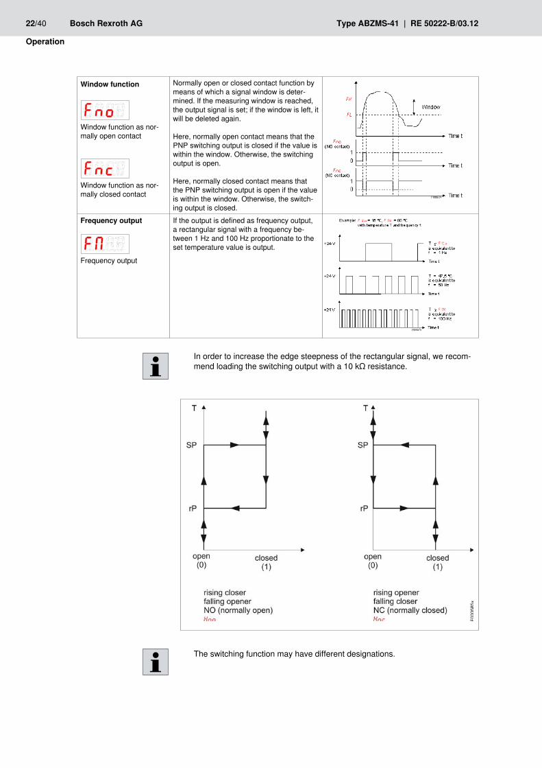
In order to increase the edge steepness of the rectangular signal, we recom-mend loading the switching output with a 10 kΩ resistance.
The switching function may have different designations.
Window function
Window function as nor-mally open contact
Window function as nor-mally closed contact
Normally open or closed contact function by means of which a signal window is deter-mined. If the measuring window is reached, the output signal is set; if the window is left, it will be deleted again.
Here, normally open contact means that the PNP switching output is closed if the value is within the window. Otherwise, the switching output is open.
Here, normally closed contact means that the PNP switching output is open if the value is within the window. Otherwise, the switch-ing output is closed.
Frequency output
Frequency output
If the output is defined as frequency output, a rectangular signal with a frequency be-tween 1 Hz and 100 Hz proportionate to the set temperature value is output.

RE 50222-B/03.12 | Type ABZMS-41 Bosch Rexroth AG 23/40
Operation
Switching output x: upper switching limit (switch-on point)4.7.2 The upper switching limit for the OUT 1 switching output is set in the following submenu:
Setting range [o.Lo]…[o.Hi]
Switching point for OUT x
The switching point must be selected within the range limits (see "Basic ext. functions" menu).
If the OUT 1 switching output has been assigned the "Window" function,
will be displayed.
The set value corresponds to the upper window limit.
If the OUT 1 switching output has been assigned the "Frequency output" function,
will be displayed.
The set value corresponds to the frequency 100 Hz.
Switching output x: Lower switching limit (switch-back point)4.7.3 The lower switching limit for the OUT 1 switching output is set in the following submenu:
Setting range [o.Lo]…[o.Hi]
Switch-back point for OUT 1
The switch-back point must be selected within the range limits.
If the OUT 1 switching output has been assigned the "Window" function, will be displayed.
The set value corresponds to the upper window limit.
If the OUT 1 switching output has been assigned the "Frequency output" function,
will be displayed.
The set value corresponds to the frequency 1 Hz
24/40 Bosch Rexroth AG Type ABZMS-41 | RE 50222-B/03.12
Operation
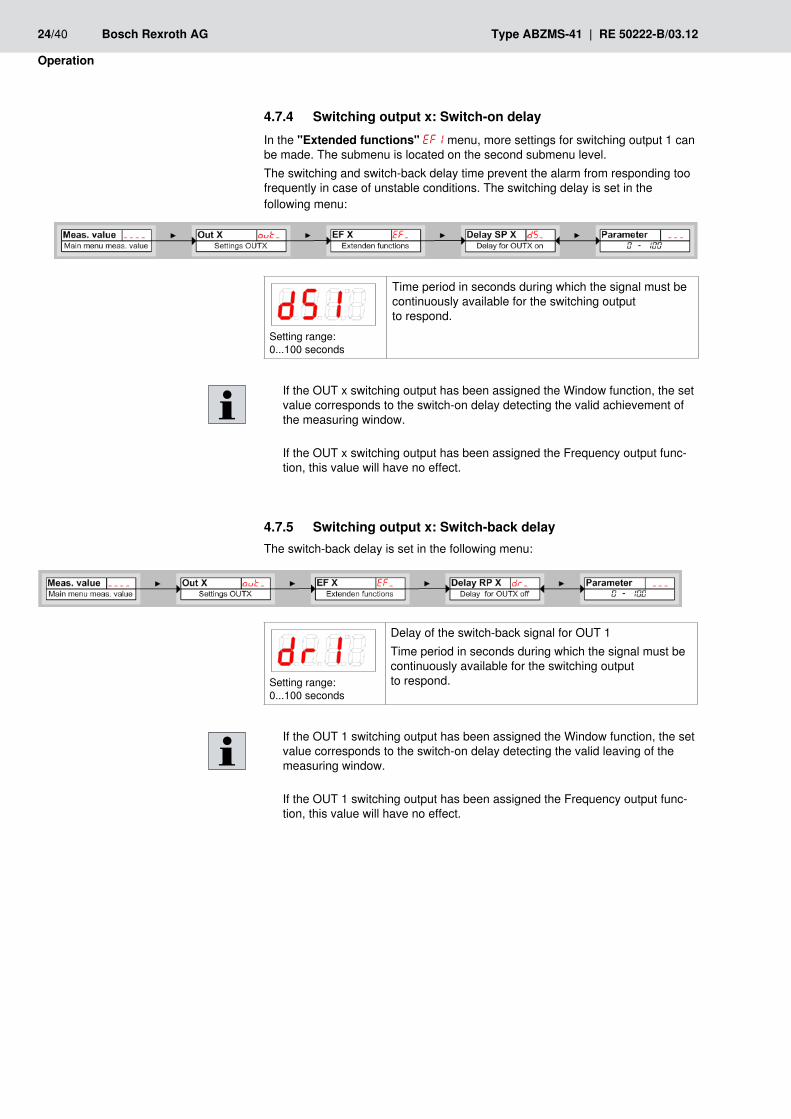
Switching output x: Switch-on delay4.7.4 In the "Extended functions" EF1 menu, more settings for switching output 1 can be made. The submenu is located on the second submenu level.The switching and switch-back delay time prevent the alarm from responding too frequently in case of unstable conditions. The switching delay is set in the following menu:
Setting range: 0...100 seconds
Time period in seconds during which the signal must be continuously available for the switching output to respond.
If the OUT x switching output has been assigned the Window function, the set value corresponds to the switch-on delay detecting the valid achievement of the measuring window.
If the OUT x switching output has been assigned the Frequency output func-tion, this value will have no effect.
Switching output x: Switch-back delay4.7.5 The switch-back delay is set in the following menu:
Setting range: 0...100 seconds
Delay of the switch-back signal for OUT 1Time period in seconds during which the signal must be continuously available for the switching output to respond.
If the OUT 1 switching output has been assigned the Window function, the set value corresponds to the switch-on delay detecting the valid leaving of the measuring window.
If the OUT 1 switching output has been assigned the Frequency output func-tion, this value will have no effect.
RE 50222-B/03.12 | Type ABZMS-41 Bosch Rexroth AG 25/40
Operation
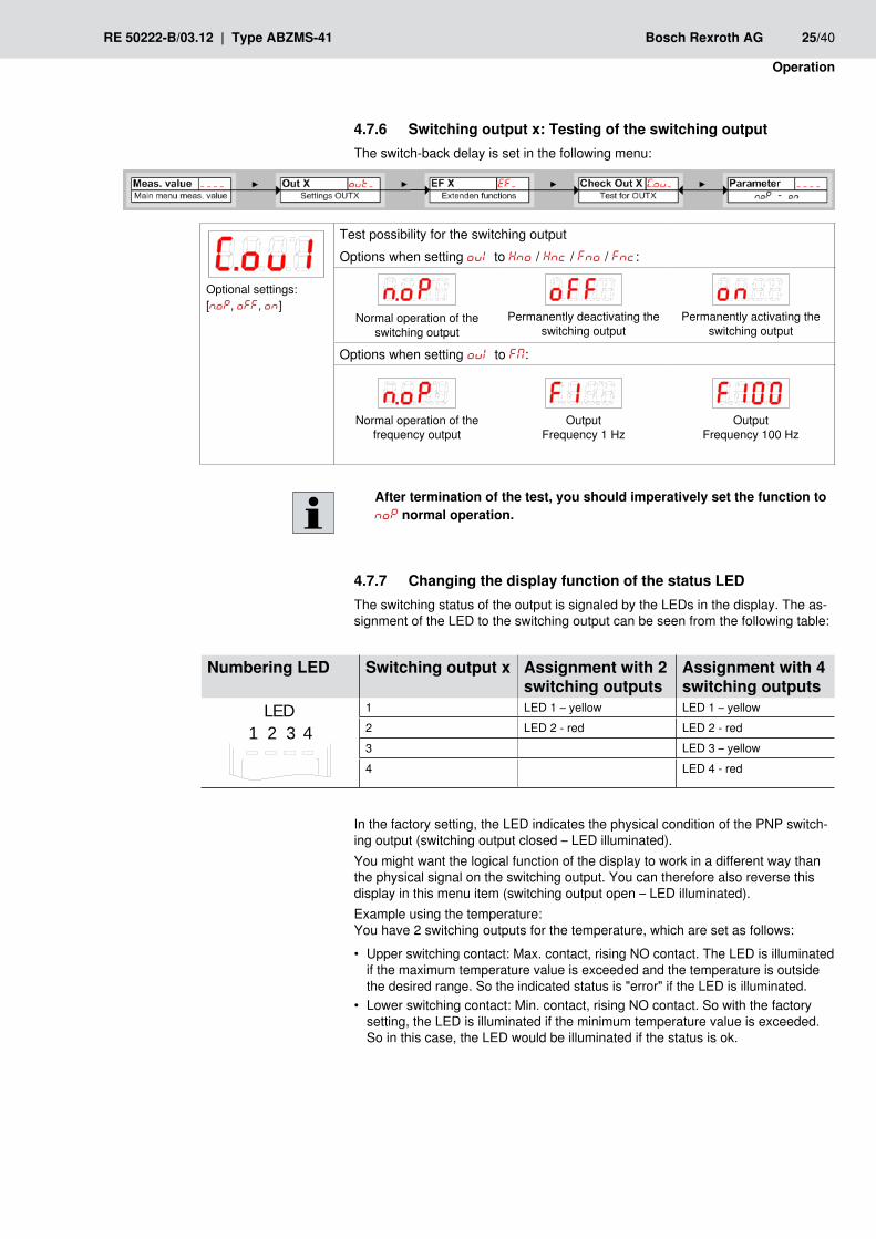
Switching output x: Testing of the switching output4.7.6 The switch-back delay is set in the following menu:
After termination of the test, you should imperatively set the function to noP normal operation.
Changing the display function of the status LED4.7.7 The switching status of the output is signaled by the LEDs in the display. The as-signment of the LED to the switching output can be seen from the following table:
In the factory setting, the LED indicates the physical condition of the PNP switch-ing output (switching output closed – LED illuminated).You might want the logical function of the display to work in a different way than the physical signal on the switching output. You can therefore also reverse this display in this menu item (switching output open – LED illuminated).Example using the temperature: You have 2 switching outputs for the temperature, which are set as follows:
Upper switching contact: Max. contact, rising NO contact. The LED is illuminated •if the maximum temperature value is exceeded and the temperature is outside the desired range. So the indicated status is "error" if the LED is illuminated.Lower switching contact: Min. contact, rising NO contact. So with the factory •setting, the LED is illuminated if the minimum temperature value is exceeded. So in this case, the LED would be illuminated if the status is ok.
Optional settings:[n.oP, off, on]
Test possibility for the switching outputOptions when setting oul to Hno / Hnc / Fno / Fnc:
Normal operation of the switching output
Permanently deactivating the switching output
Permanently activating the switching output
Options when setting oul to FM:
Normal operation of the frequency output
Output Frequency 1 Hz
OutputFrequency 100 Hz
numbering LED Switching output x Assignment with 2 switching outputs
Assignment with 4 switching outputs
LED1 2 3 4
1 LED 1 – yellow LED 1 – yellow2 LED 2 - red LED 2 - red3 LED 3 – yellow4 LED 4 - red

26/40 Bosch Rexroth AG Type ABZMS-41 | RE 50222-B/03.12
Operation
The table shows an example with the factory setting and with inverted status func-tion for LED3. The switching points are defined as follows:
SP3 = 70 °C, rP3 = 65 °CSP4 = 80 °C, rP4 = 75 °C
Here, you can reverse the LED status function for a contact: the LED is illuminat-ed if the contact is open, i.e. below the minimum temperature, and the "Error" sta-tus is indicated again if the LED is illuminated. The recording of events particularly depends on the lighting up of the LED (see chapter "Diagnosis possibilities", 4.9).
The recording of events particularly depends on the lighting up of the LED (see chapter "Diagnosis possibilities", 4.9).
Factory setting Status function LED inverted
Condition Status
A
LED3 ON LED3 OFF
Temperature increases to > 70 °CPNP switching output 3 closed
OK
B
LED4 and LED3 ON only LED4 ON
Temperature increases to > 80 °CPNP switching output 4 closed
Error
C
LED3 ON LED3 OFF
Temperature decreases to < 75 °CPNP switching output 4 open
OK
D
LED3 OFF LED3 ON
Temperature decreases to < 65 °CPNP switching output 3 open
Error
Optional settings:[L= o , L=-o]
The following options are available
LED = output;The LED is illuminated if the PNP switching
output is closed.
LED = –output;The LED is illuminated if the PNP switching
output is open.

RE 50222-B/03.12 | Type ABZMS-41 Bosch Rexroth AG 27/40
Operation
Analog outputs4.8
Analog output x: Assignment of the upper limit 4.8.1 Here, it is assigned at which temperature the maximum analog signal is to be output. The setting is made in the menu.
The set output range must not be selected to be less than 10 % of the measurement range. AI.Hi – AI.Lo >= 10 %
If the selected range is too small, the analog value output may show steps.
Analog output x: Assignment of the lower limit4.8.2 Here, it is assigned at which temperature the minimum analog signal is to be output. The setting is made in the menu.
The set output range must not be selected to be less than 10 % of the measurement range. AI.Hi – AI.Lo >= 10 %
If the selected range is too small, the analog value output may show steps.
Setting range0 °C to 100 °C(32 °F to 212 °F)
Open the value list by means of the f u key.Set the value using the f q and p keys and confirm it using the u key (e.g. 10 °C).
The device returns to the submenu.
Setting range0 °C to 100 °C(32 °F to 212 °F)
Open the value list by means of the f u key.Set the value using the f q and p keys and confirm it using the u key (e.g. 80 °C).
The device returns to the submenu.

28/40 Bosch Rexroth AG Type ABZMS-41 | RE 50222-B/03.12
Operation
Analog output x: Determining the signal form 4.8.3 The analog output can be defined as voltage or current output with different value ranges. The setting is made in the menu.
Analog output x: Testing the analog output 4.8.4 The analog output can be tested, as well. The largest, the medium and the smallest analog value can be output one after the other. The setting is made in the menu
After termination of the test, you should imperatively set the function to noP normal operation.
Open the value list by means of the f u key.Set the value using the f q and p keys and confirm it using the u key (e.g. 10L or 10 %).
The device returns to the submenu.
The following options are available:
4 mA to 20 mA
2 V to 10 V
0 V to 10 V
0 V to 5 V
The following options are available:
:Normal operation
Output highest analog value
Output medium analog value
Output lowest analog value
RE 50222-B/03.12 | Type ABZMS-41 Bosch Rexroth AG 29/40
Operation
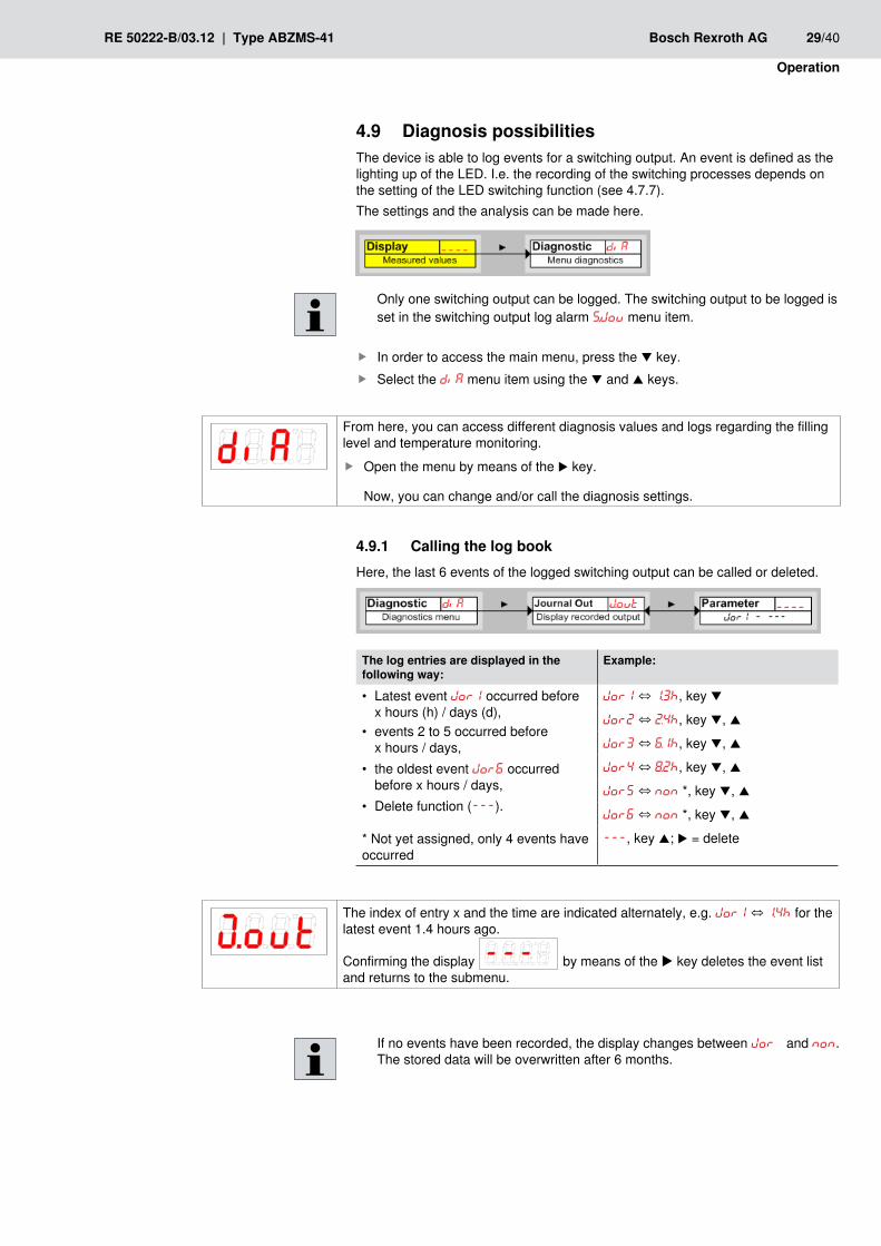
Diagnosis possibilities4.9 The device is able to log events for a switching output. An event is defined as the lighting up of the LED. I.e. the recording of the switching processes depends on the setting of the LED switching function (see 4.7.7).The settings and the analysis can be made here.
Only one switching output can be logged. The switching output to be logged is set in the switching output log alarm S..Jou menu item.
In order to access the main menu, press the f q key.Select the f diA menu item using the q and p keys.
Calling the log book4.9.1 Here, the last 6 events of the logged switching output can be called or deleted.
The log entries are displayed in the following way:
Example:
Latest event • Jor1 occurred before x hours (h) / days (d),events 2 to 5 occurred before •x hours / days,the oldest event • Jor6 occurred before x hours / days,Delete function ( • ---).
* Not yet assigned, only 4 events have occurred
Jor1 ⇔ 1.3h, key q
Jor2 ⇔ 2.4h, key q, p
Jor3 ⇔ 6.1h, key q, p
Jor4 ⇔ 8.2h, key q, p
Jor5 ⇔ non *, key q, p
Jor6 ⇔ non *, key q, p
---, key p; u = delete
If no events have been recorded, the display changes between Jorx and non. The stored data will be overwritten after 6 months.
From here, you can access different diagnosis values and logs regarding the filling level and temperature monitoring.
Open the menu by means of the f u key.
Now, you can change and/or call the diagnosis settings.
The index of entry x and the time are indicated alternately, e.g. Jor1 ⇔ 1.4h for the latest event 1.4 hours ago.
Confirming the display
by means of the u key deletes the event list and returns to the submenu.
30/40 Bosch Rexroth AG Type ABZMS-41 | RE 50222-B/03.12
Operation
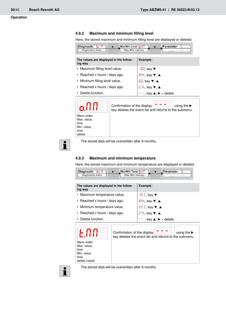
Maximum and minimum filling level4.9.2 Here, the stored maximum and minimum filling level are displayed or deleted.
The values are displayed in the follow-ing way
Example:
Maximum filling level value, • 150, key qReached x hours / days ago, • 8.4h, key q, pMinimum filling level value, • 60, key q, pReached x hours / days ago, • 2.1h, key q, pDelete function. • ---, key p; u = delete
The stored data will be overwritten after 6 months.
Maximum and minimum temperature4.9.3 Here, the stored maximum and minimum temperature are displayed or deleted.
The values are displayed in the follow-ing way
Example:
Maximum temperature value, • 72°C, key qReached x hours / days ago, • 8.4h, key q, pMinimum temperature value, • 22°C, key q, pReached x hours / days ago, • 2.1h, key q, pDelete function. • ---, key p; u = delete
Menu order:Max. value, time Min. value, time delete (reset)
Confirmation of the display
using the u key deletes the event list and returns to the submenu.
The stored data will be overwritten after 6 months.
Menu order: Max. value, time Min. value, time delete
Confirmation of the display
using the u key deletes the event list and returns to the submenu.

RE 50222-B/03.12 | Type ABZMS-41 Bosch Rexroth AG 31/40
Operation
Determining the switching output to be logged4.9.4 Here, the switching output to be logged is selected. Only one switching output can be logged.
Selection: out1 to outX
Open the value list by means of the f u key.Select the value using the f q and p keys and con-firm it using the u key.
The device returns to the submenu.
The values are stored from the volatile memory into the non-volatile one approx. every three hours.
The stored data will be overwritten after 6 months.
Delay until storage of the min/max filling level4.9.5 In order to record reliable values in case of an unstable fluid level, a delay time until storage of the minimum and maximum filling level can be set. Here, the time period in seconds is indicated during which the signal must be continuously available before the filling level will be logged.
Setting range: 0...100 seconds
Open the value list by means of the f u key.Set the value using the f q and p keys and confirm it using the u key (e.g. 5 (seconds)).
The device returns to the submenu.
Delay until storage of the min/max temperature4.9.6 In order to record reliable values in case of temperature fluctuations, a delay time until storage of the minimum and maximum temperature can be set. Here, the time period in seconds is indicated during which the signal must be continuously available before the temperature will be logged.
Setting range: 0...100 seconds
Open the value list by means of the f u key.Set the value using the f q and p keys and confirm it using the u key (e.g. 5 (seconds)).
The device returns to the submenu.
32/40 Bosch Rexroth AG Type ABZMS-41 | RE 50222-B/03.12
Maintenance
Maintenance5
Inspection and maintenance5.1 The device is working in a maintenance-free way.
Service and repair5.2 If an error occurs during operation, the following table provides troubleshooting information.If after removal of possible failures and switch-on of the mains voltage, the device does not function correctly, it must be checked by the manufacturer. For this purpose, please put the device in suitable packing and return it to one of the Bosch Rexroth service representations.Please refer to www.boschrexroth.com/adressen for addresses of service repre-sentations.
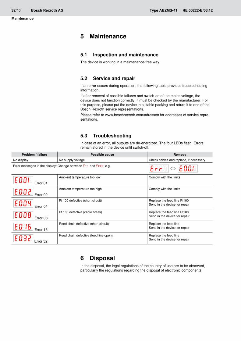
Troubleshooting5.3 In case of an error, all outputs are de-energized. The four LEDs flash. Errors remain stored in the device until switch-off.
Disposal6 In the disposal, the legal regulations of the country of use are to be observed, particularly the regulations regarding the disposal of electronic components.
Problem / failure Possible cause RemedyNo display No supply voltage Check cables and replace, if necessary
Error messages in the display: Change between Err and Exxx: e.g.
⇔
Error 01Ambient temperature too low Comply with the limits
Error 02Ambient temperature too high Comply with the limits
Error 04Pt 100 defective (short circuit) Replace the feed line Pt100
Send in the device for repair
Error 08Pt 100 defective (cable break) Replace the feed line Pt100
Send in the device for repair
Error 16Reed chain defective (short circuit) Replace the feed line
Send in the device for repair
Error 32Reed chain defective (feed line open) Replace the feed line
Send in the device for repair

RE 50222-B/03.12 | Type ABZMS-41 Bosch Rexroth AG 33/40
Technical data
Technical data7
generalInstallation position: Vertical ±10°Medium temperature range –20 to +70 °C [–4 to +158 °F]Ambient temperature range –20 to +85 °C [–4 to +185 °F]Material Sliding tube Ø 20 mm [0.79 inch] CU alloy
Float 1.4571Flange PA12 + 25GF (25 % of glass fiber)Protective tube Ø
60.3 mm [2.37 inch] Stainless steel 1.4301
hydraulicMaximum operating pressure
bar [psi] 1 [14.5]
Hydraulic fluidDensity g/cm³ > 0.8ResistanceMineral oils HLP according
to DIN 51524Resistant
Flame-resistant Emulsions HFA-E according to DIN 24320
Resistant
Water solutions HFC ResistantPhosphoric acid esters HFD-R according
to VDMA 24317Resistant
Organic esters HFD-U ResistantFast biodegradable Triglycerides
(rape seed oil)HETG Resistant
Synthetic esters HEES ResistantPolyglycols HEPG Resistant
34/40 Bosch Rexroth AG Type ABZMS-41 | RE 50222-B/03.12
Technical data
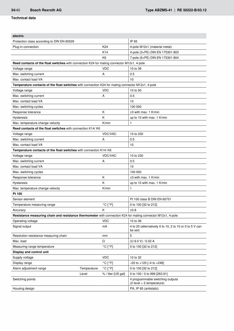
electricProtection class according to DIN EN 60529 IP 65Plug-in connection K24 4-pole M12x1 (material metal)
K14 4-pole (3+PE) DIN EN 175301-803K6 7-pole (6+PE) DIN EN 175301-804
Reed contacts of the float switches with connection K24 for mating connector M12x1, 4-poleVoltage range VDC 10 to 36Max. switching current A 0.5Max. contact load VA 10Temperature contacts of the float switches with connection K24 for mating connector M12x1, 4-poleVoltage range VDC 10 to 50Max. switching current A 0.5Max. contact load VA 10Max. switching cycles 100 000Response tolerance K ±3 with max. 1 K/minHysteresis K up to 10 with max. 1 K/minMax. temperature change velocity K/min 1Reed contacts of the float switches with connection K14/ K6Voltage range VDC/VAC 10 to 230Max. switching current A 0.5Max. contact load VA 10Temperature contacts of the float switches with connection K14/ K6Voltage range VDC/VAC 10 to 230Max. switching current A 0.5Max. contact load VA 10Max. switching cycles 100 000Response tolerance K ±3 with max. 1 K/minHysteresis K up to 10 with max. 1 K/minMax. temperature change velocity K/min 1Pt 100Sensor element Pt 100 class B DIN EN 60751Temperature measuring range °C [°F] 0 to 100 [32 to 212]Accuracy K ±0.8Resistance measuring chain and resistance thermometer with connection K24 for mating connector M12x1, 4-poleOperating voltage VDC 10 to 36Signal output mA 4 to 20 (alternatively 0 to 10, 2 to 10 or 0 to 5 V can
be set)Resolution resistance measuring chain mm 5Max. load Ω (U-9.0 V) / 0.02 AMeasuring range temperature °C [°F] 0 to 100 [32 to 212]Display and control unitSupply voltage VDC 10 to 32Display range °C [°F] –20 to +120 [–4 to +248]Alarm adjustment range Temperature °C [°F] 0 to 100 [32 to 212]
Level % / liter [US gal] 0 to 100 / 0 to 999 [263.91]Switching points 4 programmable switching outputs
(2 level + 2 temperature)Housing design PA, IP 65 (antistatic)

RE 50222-B/03.12 | Type ABZMS-41 Bosch Rexroth AG 35/40
Appendix: Overview menu sequence
Appendix: Overview menu sequence8
Display 4 digit seven-segment LED displayCurrent consumption upon switch-on approx. 100 mA for 100 msCurrent consumption in operation approx. 50 mA with UB 24 VSwitching output PNP, max. 0.5 A switching powerMax. ambient temperature °C [°F] –20 to +70 [–4 to +158]Accuracy 1 % of the measurement range end valueOperation 3 keys

36/40 Bosch Rexroth AG Type ABZMS-41 | RE 50222-B/03.12
Appendix: Overview menu sequence

RE 50222-B/03.12 | Type ABZMS-41 Bosch Rexroth AG 37/40
Appendix: Overview menu sequence

38/40 Bosch Rexroth AG Type ABZMS-41 | RE 50222-B/03.12
Appendix: Overview menu sequence

RE 50222-B/03.12 | Type ABZMS-41 Bosch Rexroth AG 39/40
Appendix: Overview menu sequence

Bosch Rexroth AGHydraulicsZum Eisengießer 197816 Lohr am Main, GermanyPhone: +49 (0) 93 52 - 18 0 [email protected]
Printed in GermanyRE 50222-B/03.12