Fire Protection & Fire Fighting System PROTECTION AND FIRE... · WBSETCL / TECH SPEC / Rev.-2 Page...
16
WBSETCL / TECH SPEC / Rev.-2 Page 1 of 16 Fire Protection & Fire Fighting System Fire Protection & Fire Fighting System August 2015 Engineering Department WEST BENGAL STATE ELECTRICITY TRANSMISSION COMPANY LIMITED Regd. Office: VidyutBhawan, Block – DJ, Sector-II, Bidhannagar, Kolkata – 700091. CIN: U40101WB2007SGC113474; Website: www.wbsetcl.in
Transcript of Fire Protection & Fire Fighting System PROTECTION AND FIRE... · WBSETCL / TECH SPEC / Rev.-2 Page...

WBSETCL / TECH SPEC / Rev.-2 Page 1 of 16 Fire Protection & Fire Fighting System
Fire Protection & Fire
Fighting System
August 2015
Engineering Department
WEST BENGAL STATE ELECTRICITY TRANSMISSION COMPANY LIMITED
Regd. Office: VidyutBhawan, Block – DJ, Sector-II, Bidhannagar, Kolkata – 700091.
CIN: U40101WB2007SGC113474; Website: www.wbsetcl.in

WBSETCL / TECH SPEC / Rev.-2 Page 2 of 16 Fire Protection & Fire Fighting System
TECHNICAL SPECIFICATION FOR FIRE PROTECTION
AND FIRE FIGHTING SYSTEM
1. SCOPE :
This specification covers design, engineering, supply, delivery, erection, testing and commissioning of fire protection and firefighting system for equipment, pump house, Control
Room Buildings, Diesel Generator room etc. at different Sub-station. For existing Sub Station,
scope of work shall be guided by supply & erection schedule & Technical Specification.
This specification covers the design and performance requirement of the following types of fire protection system.
a) Fire Detection System. b) Portable Fire Extinguishers.
c) Wheel/Trolley mounted Fire Extinguisher d) Hydrant System
e) High velocity water (H.V.W) Spray System (For 400/220/132/33KV S/stn. Only). f) Diesel Engine driven stand by pump.
g) Diesel Engine
The system design and equipment shall conform in all respects to high standard of engineering,
design and workmanship and shall be capable of performing in continuous commercial operation in a manner acceptable to the owner.
The system design shall also conform to TAC/NFPA norms. Scope of works for Fire Protection & fire fighting system shall be guided by schedule & technical specification.
a) The scope of work include complete earthwork (i.e. excavation, back filling etc.) for the
entire piping (underground & overhead) for the system, valve pits and pipe/support
structures for buried, entrenched and over ground piping.
b) The equipment offered shall comply with the relevant Indian Standards and shall meet the
requirement called for in the latest revision of relevant Indian Standard at the time of tendering.
c) Ambient temperature for design of all equipment shall be considered as 50°C.
d) The Contractor shall prepare detailed layout and piping drawing based on this technical
specification and approved switchyard layout drawing and other drawing such as road,
drainage, cable trench etc. of sub-station.
e) Detailed layout and piping drawing shall be such that in future extension of bays towards
control room building and opposite to control room building should not be obstructed due to laying of pipe line and other fire fighting accessories under the present scope of work.
f) Detailed design, pipe line layout and the capacity of pump-motor selected for
the system shall be such that it will cater all the possible future bay and transformer / reactor extension in switchyard only by extending the existing
pipe line from nearest point.
g) Provision shall be kept in piping layout for its extension for the future bays on both sides of
the switchyard.
WBSETCL / TECH SPEC / Rev.-2 Page 3 of 16 Fire Protection & Fire Fighting System
h) Fire Notice for Fire Fighting and evacuation from the building shall be prepared and to be
displayed at all vulnerable places of building.
i) First Aid Fire Fighting arrangement in the style of placing suitable type of portable Fire
Extinguishers, Fire Buckets etc. in all floors and vulnerable location of the Sub-Station premises shall be made in accordance with IS: 2190 – 1992.
2. STANDARDS :
Fire equipments, design and layout of fire protection system shall conform to the latest edition of the following standard as well as this specification.
(i) IS:1646 : Code of practice for fire safety of buildings (General: electrical installation)
(ii) IS :1647 : Code of practice for fire fighting of buildings
(iii) IS:1648 Code of practice for fire fighting of buildings, fire
fighting equipment and its maintenance.
(iv) IS:2189 : Code of practice for erection, installation and maintenance of automatic fire detection and
alarm.
(v) IS:2190 : Selection, installation and maintenance of first aid
fire extinguisher code of practice.
(vi) Tariff Advisory Committee
Manual.
(vii) National Fire Protection Authority of America Manual.
3. I) DEVIATIONS :
Normally the offer should be as per Technical Specification without any deviation.
II) MODIFICATION :
If any modification felt necessary to improve performance, efficiency and utility of equipment,
the same must be mentioned in the 'Modification schedule' with reasons duly supported by documentary evidences and advantages. Such modifications suggested may or may not be
accepted, but the same must be submitted along with Pre-Bid Queries. The modifications not
mentioned in Schedule will not be considered.
4. SOCK PIT, Oil/Water Sump, Sump Pump house, Fire fighting pump house: For construction details & other Civil aspect ref., Tech. Spec.(Civil).
WBSETCL / TECH SPEC / Rev.-2 Page 4 of 16 Fire Protection & Fire Fighting System
5. HYDRANT SYSTEM:
Hydrant System of fire protection essentially consists of a large network of pipe, combination of
underground and over ground fed with pressurized water to a number of hydrant valves inside
the switchyard as well as outside switchyard. These hydrant valves are to be located at strategic locations near buildings, Transformers, and Reactors and other electrical equipments.
Hose Pipe of suitable length and fitted with standard accessories like branch pipes, nozzles etc. are to be kept in Hose Boxes. In case of emergency these hoses are to be coupled to the
respective hydrant valves through instantaneous coupling and jet of water is to be directed to the equipment under fire hydrant protection shall cover the following:
(a) Control room building (b) All Pump House, Stores.
(c) All switchyard equipment area including all power transformer and reactors. (d) D.G. Set Building.
Provision of Hose Reel in conjunction with wet Riser shall be made at each floor level of Control Building / GIS Building conforming relevant I.S. Specification.
Hydrant System shall be so designed that minimum required water pressure shall be available
at the farthest point of the switchyard. Farthest point shall be taken as considering the present scope of construction of bays as well as future bays as possible according to available space at
switchyard as per approved LUP & Structural Plan drawing of a particular new sub-station.
One no. of warning plate is to be kept near all the hydrant points to be utilized for combating
fire hazard of power transformer and bus-reactor. Water shall be sprayed only after checking that the power to the transformer/reactor has been made off and no live parts is there within
20 metre distance from the person using the hydrant.
6. HIGH VELOCITY WATER SPRAY (HVWS) SYSTEM (For 400KV Sub-station):
HVWS type fire protection essentially consists of a network of projectors and an array of heat
detectors around 400 KV Power Transformer and 400 KV Bus Reactor to be protected from fire. On operation of one or more heat detectors, water under pressure is to be directed to the
projector network through a Deluge Valve from the pipe network laid for this automatic operation system. Wet detection initiation system shall be employed for automatic operation.
The system shall be designed in such a way that the same can be extended to protect two more 400 KV Transformer / Reactor to be installed in future. However
design consideration shall be on the basis of considering only one Transformer / Reactor of highest MVA/MVAR rating will be on fire at a time. The system shall be designed to have a
suitable pressure and suitable water quantity/hr. at the farthest transformer / reactor location
as per approved layout drawing.
The minimum Electrical clearance values between the Emulsifier system pipe work and live parts of the protected 400 KV Transformers / reactor are to be maintained as furnished below.
1. 420 KV Bushing : 3500 mm
2. 245 KV Bushing : 2150 mm
3. 145KV Bushing : 1300 mm. 3. 52 KV Bushing : 630 mm
4. 36 KV Bushing : 320 mm.
WBSETCL / TECH SPEC / Rev.-2 Page 5 of 16 Fire Protection & Fire Fighting System
Minimum water pressure available at the farthest and /or highest projector on the equipment protected shall be 3.5 kg/cm 2 However water pressure available at any projector shall not
exceed 5.00 kg./cm 2.
Contractor has to specify applied rate of water in LPM /M 2 of the surface area of the entire 400
KV transformer / Reactor. Area of transformer / reactor shall be calculated considering radiator, conservator, bottom surface of transformer/reactor etc.
Deluge Valve shall be provided in conjunction with H.V.W spray system. Normally Deluge Valve
shall be closed watertight. On fall of water pressure due to opening of one or more heat detector the valve shall open and water shall rush to the spray water network through the
open Deluge Valve. The valves shall be manually reset to initial position after completion of
entire operation. One water motor gong is to be provided with each Deluge Valve for audible alarm. The alarm will be initiated when water is tapped through the water motor after passing
the Deluge Valve.
Each Deluge Valve shall be provided with a local panel for the purpose of manual electrical
operation of the valve. Additionally latch is to be provided for local operation.
HIGH VELOCITY SPRAY NOZZLES (PROJECTOR):
High velocity water spray system shall be designed and installed in order to discharge water in
the form of a conical spray consisting of droplets of water traveling at high velocity which shall strike the burning surface of 400 KV Transformer/Reactor with sufficient impact to ensure the
formation of an emulsion. At the same time the spray shall also be able to efficiently cut off oxygen supply and provide sufficient cooling.
Minimum set point of the heat detectors used in HVW Spray System shall be specified by the Contractor. However, the optimum rating shall be suggested by the Contractor as per the
attainable maximum and minimum temperature at site.
7. WATER SUPPLY SYSTEM:
a) For 400/220/132/33 KV Sub-station
Water for hydrant and High Velocity Water (H.V.W) Spray System shall be supplied with the
help of one electrical motor driven pump with another pump driven by diesel engine to be kept as standby. The diesel engine driven stand by pump shall operate when the header pressure is
low or the motor driven pump fails to start. One number diesel engine of suitable rating is also to be provided for this purpose.
Two numbers water storage tanks of suitable capacity shall be constructed (guided by relevant Technical Specification -Civil). The capacity of the pump shall be decided according to the
norms of TAC (Tariff Advisory Committee Manual).
The whole system will be kept pressurized with the help of air vessel of adequate capacity and two numbers jockey pumps & motors. Jockey pump shall take care, if there is any minor
leakage. One set of which shall be provided by the contractor as standby. The pumps and air
vessel with all auxiliary equipment will be located in fire water pump house.
WBSETCL / TECH SPEC / Rev.-2 Page 6 of 16 Fire Protection & Fire Fighting System
Annunciation of the hydrant and HVW spray system shall be provided in fire water pump house
and repeated in 400 KV control room. The capacity of air vessel shall be adequate and to be specified by the bidder.
Operation of all the pumps shall be automatic and shall be brought into operation at preset
pressure. Fire pumps can be stopped manually only. Manual start/stop provision shall be
provided in local control panel. Compound system i.e. both hydrant and HVSW shall comprise of Reservoir, Suction pipes, composite piping system delivery pipe etc. up to common intake point.
Piping for hydrant as well as HVSW shall be teed off from power intake or suitable point of the delivery pipe for hydrant as well as HVSW system. Pipe sizes shall be designed by the
contractor for successful operation of the entire firefighting system (considering future scope also).
Outdoor piping of the system in general shall be laid above ground with proper supports. However at road/rail/cable trench crossing, in front / access of buildings including C.R.B.,
places were movement of cranes/vehicles/replacement of any equipments in present and future and at any other places where above ground piping is not advisable, the pipes shall be laid
underground. Such location shall be finalized during detailed engineering.
The offered horizontal centrifugal pumps along with drives and accessories shall meet the
requirement of TAC.
Each pump is to be provided with a nameplate having all important technical particulars.
Design, construction, erection, testing and trial operation of piping, valves, strainers, hydrant
valves, hoses, nozzles, branch pipe, hose boxes, expansion joints and other accessories shall conform to the requirement of relevant IS & TAC.
b) For 220/132/33KV & 132/33KV Sub-station
Water for hydrant for 220/132/33KV & 132/33KV substations shall be supplied by one electric
motor driven pump and another pump, driven by diesel engine, shall be used as standby. The diesel engine driven standby pump shall operate when the header pressure is low, or the
motor driven pump fails to start. Water storage tank of adequate capacity, which shall be
decided as per norms of TAC, is to be provided accordingly. Annunciations of the hydrant system shall be provided in a separate annunciation panel, to be located in the pump room.
The outdoor piping for the system in general shall be laid above ground on concrete
pedestals with proper clamping. However at road/ rail crossings, in front access of buildings, places where movement of cranes / vehicles is expected and at any other place where laying
of pipe above ground is not advisable, the pipes shall be laid underground. Such locations
shall be finalised during detailed engineering and after approval of all relevant substation drawings.
c) The hydrant system has to be designed in such a way that minimum pressure of 3.5 Kg/Sq.
cm at the farthest point shall be available after considering all the head losses and also operation of two hydrants simultaneously.
d) Surface of all overground pipes shall be thoroughly cleaned of mill scale, rust etc. by wire brushing. Thereafter one (1) coat of red lead primer of best quality (IS marked) shall be
applied. Finally, two (2) coats of synthetic enamel paint of best quality (IS marked) shall be
applied. For underground piping, coating & wrapping shall be done with two coats of coal tar/ hot enamel paint & two wraps of reinforced fibre glass tissue. The total thickness of coating &
wrapping shall not be less than 3 mm. Coating and wrapping shall be in line with IS: 10221.
WBSETCL / TECH SPEC / Rev.-2 Page 7 of 16 Fire Protection & Fire Fighting System
e) Detail of Instrumentation and control system for combined system of hydrant and H.V.S.W.
shall be submitted by the Contractor.
8. POWER SUPPLY, CONTROL & ANNUNCIATION PANELS:
Power supply will be from two different source of A.C. Distribution Board located in control
room building. These two sources will be terminated at the incomer panel located in pump house. The changeover arrangement will be there to select either source. The control supply
for local control panels, annunciation panels, battery charger units etc. shall be fed from the AC and DC distribution boards located at fire pump room.
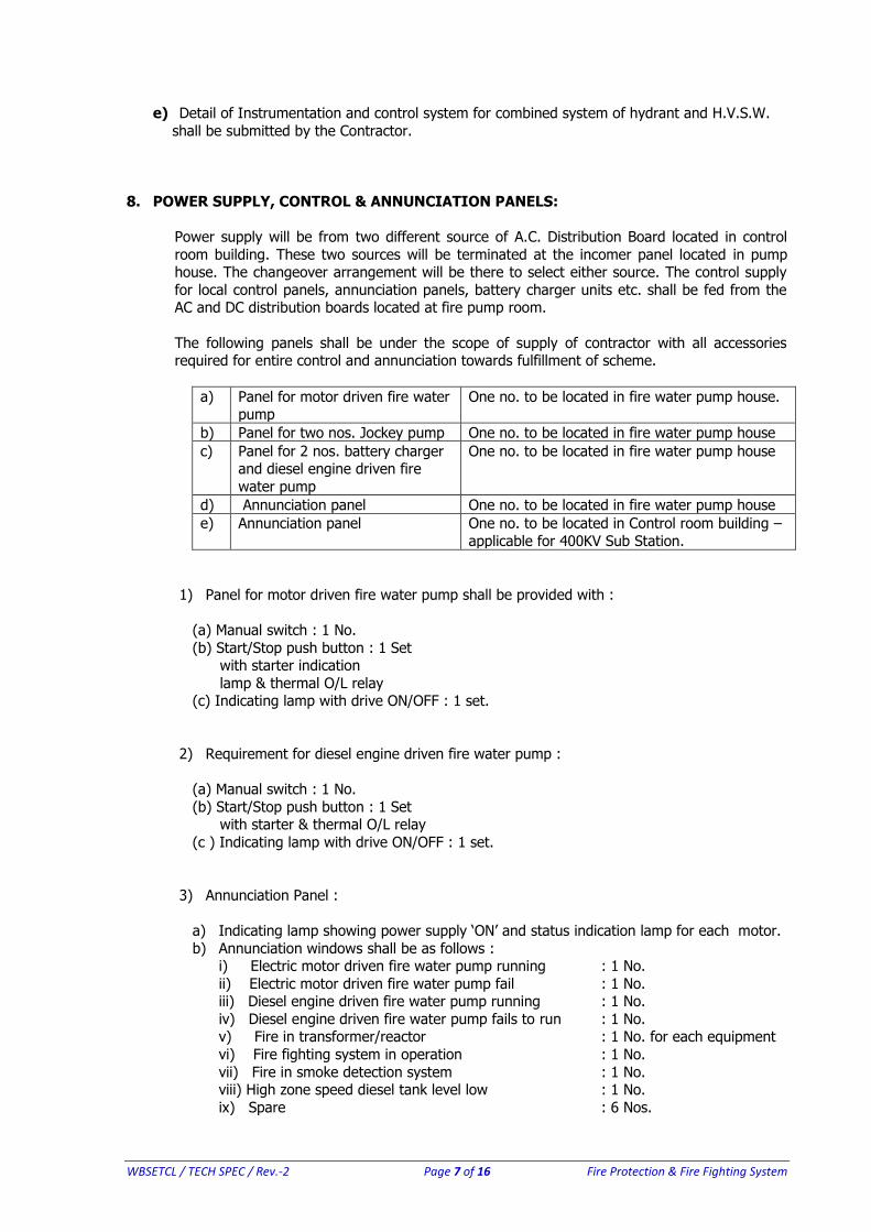
The following panels shall be under the scope of supply of contractor with all accessories required for entire control and annunciation towards fulfillment of scheme.
a) Panel for motor driven fire water pump
One no. to be located in fire water pump house.
b) Panel for two nos. Jockey pump One no. to be located in fire water pump house
c) Panel for 2 nos. battery charger and diesel engine driven fire
water pump
One no. to be located in fire water pump house
d) Annunciation panel One no. to be located in fire water pump house
e) Annunciation panel One no. to be located in Control room building –
applicable for 400KV Sub Station.
1) Panel for motor driven fire water pump shall be provided with :
(a) Manual switch : 1 No.
(b) Start/Stop push button : 1 Set with starter indication
lamp & thermal O/L relay (c) Indicating lamp with drive ON/OFF : 1 set.
2) Requirement for diesel engine driven fire water pump :
(a) Manual switch : 1 No.
(b) Start/Stop push button : 1 Set with starter & thermal O/L relay
(c ) Indicating lamp with drive ON/OFF : 1 set.
3) Annunciation Panel :
a) Indicating lamp showing power supply ‘ON’ and status indication lamp for each motor.
b) Annunciation windows shall be as follows : i) Electric motor driven fire water pump running : 1 No.
ii) Electric motor driven fire water pump fail : 1 No. iii) Diesel engine driven fire water pump running : 1 No.
iv) Diesel engine driven fire water pump fails to run : 1 No. v) Fire in transformer/reactor : 1 No. for each equipment
vi) Fire fighting system in operation : 1 No.
vii) Fire in smoke detection system : 1 No. viii) High zone speed diesel tank level low : 1 No.
ix) Spare : 6 Nos.
WBSETCL / TECH SPEC / Rev.-2 Page 8 of 16 Fire Protection & Fire Fighting System
All the control and annunciation panels to be supplied for smooth operation of fire fighting scheme both hydrant and HVW spray system shall be complete with supply of all accessories of
reputed make. All control and annunciation panel shall be made of sheet steel having 3 mm. Thick. Cable entries shall be from bottom with supply of suitable removable gland plate and
cable glands as per requirement. Repeater of annunciation panel shall be located at main
control room of Control building.
All indoor panel wiring and bus wiring for A.C & D.C supplies shall be under the scope of the contractor. All wiring shall be carried out with 1100V grade PVC insulated with multi core,
having size of 2.5 sq.mm. or above stranded copper wires.
Spare contacts of all auxiliary relays, timers and switches shall be wired up to terminal blocks. A
minimum gap of 100 mm. shall be maintained in between two sets of terminal block. Terminal blocks shall have at least 20% spare terminal blocks. Terminals blocks shall be Elmex make
and of 1100 V grade.
Suitable grounding arrangement with copper bus of suitable sizes at both ends is to be
provided.
Space heater, lights, control selector switches, push buttons, indicating lamps, fuses, contactors, relays, timer, indicating instruments/Annunciation etc. shall be within the scope of
supply. All the item shall be of best quality and from reputed manufacturers.
Finishing paint on outside of all panels shall be of shade 692 (smoke grey) of IS:5 and that for
inside of panels shall be glossy white.
All the control and annunciation panel shall be subject to all routine and acceptance tests as per relevant Indian Standard. Routine & acceptance Test Reports are to be submitted to WBSETCL.
All MCCBs, MCBs & Air Circuit Breakers shall be from one of the following manufacturer’s complying with technical specification & relevant IS & IEC
a) M/s Siemens b) M/s L & T
c) M/s ABB
d) M/s Schneider
9. CONTROL AND INTERLOCK SYSTEM:
a) Electric Motor Driven Fire Water Pump.
Pump should start automatically under any of the following condition :
i) HVW spray or Hydrant system header pressure low.
ii) Operation of any deluge valve. Pump should be stopped manually only. Arrangement shall be there so that pump can be
started manually in case of requirement.
b) Diesel Engine Driven Standby Pump
The pump should automatically start under any of the following condition. i) Header Pressure low.
ii) Electric motor operated fire water pump fails to start.
WBSETCL / TECH SPEC / Rev.-2 Page 9 of 16 Fire Protection & Fire Fighting System
iii) Pump should be stopped manually only.
iv) Arrangement for manual starting of pump is also to be made from local control panel.
c) Jockey Pump
Jockey pump shall start automatically when water pressure in header fall, below the sets value. Jockey pump shall stop automatically when the pressure is normal.
10. SUBMISSION OF TEST REPORT:
Routine and acceptance tests of all equipment and accessories shall be conducted as per provision in relevant standards. All tests certificates and reports shall be submitted to
W.B.S.E.T.C .L.
11. SITE TESTS AFTER INSTALLATION:
Following site tests shall be conducted up to the satisfaction of WBSETCL.
a) All piping and valves after installation will be tested hydraulically at pressure of 1.5 times that of the maximum attainable pressure in the system to check against leak tightness.
b) All manually operated valves/gates shall be operated throughout 100% of the travel and
these should function without any trouble whatsoever to the satisfaction of the employer.
c) All pumps shall be run with the specified fluid from shut off condition to valve wide open
condition Head developed will be checked from the discharge pressure gauge reading. During the test the pumps and drives shall run smoothly without any undue vibration,
leakage through gland, temperature rise in the bearing parts, noise, flow pulsation etc.
d) All pressure vessels should be tested hydraulically at the specified test pressure singly or in the system.
e) Visual check on all structural components, welding painting etc.
f) Automatic starting of all the fire pumps by operating the test valves.
g) Automatic operation of the jockey pump.
h) Operation of the automatic Control Valve by operating the test valve and remote operating of solenoid valve.
i) Operation of the entire annunciation system.
After installation at site, the complete HVW spray protection and hydrant system shall be subject to tests to show satisfactory performance as per relevant standard/code.
All the detectors installed shall be tested for actuation by bringing a suitable source of heat/smoke near the detector and creating a stream of hot air/smoke over the detector.
12. HORIZONTAL CENTRIFUGAL PUMPS:
a) The material of the various components shall conform to the applicable IS and any other relevant international Standards. Service to be provided by Horizontal centrifugal pumps
shall be as per TAC regulation.
WBSETCL / TECH SPEC / Rev.-2 Page 10 of 16 Fire Protection & Fire Fighting System
b) The pump set shall be suitable for continuous operation at any point within the “Range of
Operation”. All the centrifugal pumps shall be Indoor located.
c) The pump motor set shall be designed in such a way that no damage will occur due to
reverse flow through the pump.
d) Pumps shall have a continuously rising head capacity characteristic from the specified duty
point toward shut off point the maximum being at shut off point.
e) During starting under reverse flow condition the motor shall be capable of bringing the pump to rated speed at normal direction with 90 % rated voltage at motor terminals.
f) All rotating components shall be statically and dynamically balanced.
g) Routine and acceptance tests of horizontal centrifugal pump shall be conducted as per
provisions in relevant standard. All test certificates and reports shall be submitted to WBSETCL.
13. DIESEL ENGINE:
a) The diesel engine shall be of multi cylinder type four stroke cycle with mechanical (airless )
injection cold starting type.
b) The continuous engine break horse power rating at the site condition shall be at least 20%
greater than the requirement at the duty point of pump at rated RPM.
c) Rated output of the engine should fulfill the requirement of firefighting system (present
scope as well as future provision).
d) Both automatic and manual starting shall be possible. Normally automatic starting shall be
employed.
e) The offered diesel engine shall be with special features so that it can be started within a very short period against full load after a considerable period of idleness.
f) Batteries shall be used only for starting the diesel engine and shall be always kept under fully charged condition. Battery shall be associated with two battery charger units having
air-cooling arrangement. Both trickle charging and boost charging arrangement are to be
provided. The supplied charger unit shall be capable of charging one set of battery at a time. Provision shall however be made so that any one of the charger units can be utilized
for charging either of the two batteries.
g) Automatic cranking shall be effected by D.C motor having high starting torque to overcome
full engine compression. Starting power will be supplied from either of the two sets of
storage batteries. The automatic starting arrangement shall include a ‘Repeat Start’ feature. The battery capacity shall be adequate for 10 (ten) consecutive starts without recharging
with a cold engine under full compression.
h) Contractor shall indicate the required battery voltage and battery capacity in Ampere-Hour
at (10) hour discharge rate basis. The battery voltage at any time during operation shall not be less than the minimum voltage required for operation of D.C. loads.
i) Provision for Automatic as well as manual charging of Battery shall be kept. The boost
charger shall have sufficient capacity to restore a fully discharged Battery to a state of full charge in eight (8) hours with some spare margin over maximum charging rate
j) The governor shall offer following features :
i) Engine should be provided with an adjustable governor capable of regulating engine
speed within 5% of its rated speed under any condition of load between shut-off and
maximum load conditions of the pumps. The governor shall be set to maintain rated pump speed at maximum pump load.
WBSETCL / TECH SPEC / Rev.-2 Page 11 of 16 Fire Protection & Fire Fighting System
ii) Engine shall be provided with an over speed shut-down device. It shall be arranged to
shut-down the engine at a speed approximately 20% above rated engine speed and for manual reset, such that the automatic engine controller will continue to show an over
speed signal until the device is manually reset to normal operating position (Vol.II. NFPA.1978)
iii) The governor shall be suitable for operation without external power supply.
k) Fuel System:
The diesel engine will run on High Speed Diesel.
The engine shall be provided with fuel oil tank having adequate capacity to hold sufficient fuel oil for a minimum of six (6) hours of full load run. The fuel oil tank shall preferably be
mounted near the engine. No. fuel oil tank will be provided by the WBSETCL.
The fuel oil tank shall be of welded steel constructed to relevant standards for mild steel
drums. The outlet of the tank shall be above the inlet of fuel injection pump
The fuel tank shall be designed in such a way that the sludge and sediment settles down to
the tank bottom and is not carried to the injection pump. A small sump shall be provided and fitted with drain plug to take out sludge/sediment and to drain oil. Adequate hand
holes (greater than 80 mm. Size) shall be provided to facilitate maintenance.
Pipeline carrying fuel oil shall be gradually sloped from the tank to the injection pump. Any valve in the fuel feed pipe between the fuel tank and the engine shall be placed adjacent to
the tank and it shall be locked in the open position. A filter shall be incorporated in this
pipeline in addition to other filters in the fuel oil system. Pipe joints shall not be soldered and plastic tubing shall not be used. Reinforced flexible pipes may also be used.
The complete fuel oil system shall be designed to avoid any air pocket in any part of the
pipe work, fuel pump, sprayers/injectors, filter system etc. No air relief cock is permitted.
However, where air relief is essential plugs may be used.
A manual fuel pump shall be provided for priming and releasing of air from the fuel pipelines.
14. MAIN MOTOR & STANDBY MOTOR:
The fire fighting main motor and standby motor shall be of 3 –phase 400 V squirrel cage type
induction motor and suitable for continuous duty in the specified ambient temperature of
50°C. Rating of motor shall be decided by the bidder as per stipulated norms of TAC and fire fighting system requirement. Calculation of motor rating is to be furnished during detailed
engineering. Motors to be installed outdoor or semi-outdoor shall have hose proof enclosure and shall be equivalent to IP –55 as per IS:4691. For indoor type the enclosure shall be dust
proof as per IS : 4691. Offered motors shall be TEFC (totally enclosed fan cooled) type and
suitable for full voltage direct-on-line starting. Starting current at rated voltage shall not exceed six times of the rated full load current subject to tolerance as per IS:325.
Maximum permissible temperature rise under running condition shall be as per IS:325.
Motor shall be capable of running at 80% of rated voltage for 5 minutes with rated load
commencing from hot condition and able to develop rated full load torque for 1 second if
supply voltage drop to 70% of rated voltage.
WBSETCL / TECH SPEC / Rev.-2 Page 12 of 16 Fire Protection & Fire Fighting System
Motor shall be capable of withstanding electro-dynamic stresses and heating imposed if it is
started at a voltage of 110% of the rated voltage.
Rating plate with all particulars as per stipulation of IS:325 is to be provided.
All routine and acceptance test reports are to be submitted.
After installation and commissioning at site, the motors along with the driven equipment
shall be subject to tests. If any abnormality / defects observed during testing, necessary rectification / replacement to be made free of cost.
15. PIPING SYSTEM:
a) The piping system shall cover all the accessories required for successful erection,
commissioning and testing of total hydrant as well as H.V.W.S system required for fighting
fire of all locations as and when required.
b) Buried pipes: Mild steel black pipes as per IS:1239, Part-I, medium grade ( for pipes of size
150 Nominal Bore and below) or IS:3589, Fe 410 grade ( for pipes of size 200 Nominal Bore and above ) suitably treated on the outside to prevent soil corrosion.
c) Over ground pipes: Mild steel black or galvanized pipes as per IS:1239 Part-I, medium grade ( for pipes for sizes 150 Nominal Bore and below ) or IS: 3589, Fe 410 grade (for
pipes of size 200 Nominal Bore and above)
d) All fittings and accessories, valves, Basket Strainer, Nozzles, Branch pipes, Hose boxes, etc are to be supplied as per requirement of smooth operation of fire fighting system both
hydrant as well as H.V.W.S as per relevant IS and Codes.
e) Jointing of pipes, welding etc. shall be of quality and guided by requirement of fire fighting
system and relevant IS.
f) Surface of all over ground pipes shall be thoroughly cleaned of mill, scale rust etc. by wire brushing. Thereafter one (1) coat of red lead primer of best quality (IS approved ) shall be
applied. Finally two (2) coats of Synthetic enamel paint of best quality(IS approved) colour shall be applied.
g) The outdoor piping for the system shall be laid above ground on concrete pedestals with
proper clamping. However at rail/road crossing in front access of buildings places where movement of cranes/vehicle is expected and at any other places where laying of pipe
above ground is not advisable the pipes shall be laid underground. Such locations shall be finalized during detailed engineering and approval of all relevant sub-station drawings.
Pipes to be buried underground shall be provided with protection against soil corrosion by coating and wrapping with two coats of Coal tar hot enamel paint and two wraps of
reinforced fibre glass tissue. The total thickness of coating and wrapping shall not be less
than 3 mm. Alternatively corrosion resistance tapes can also be used for protection of pipes against corrosion. Coating and wrapping shall be in line with IS : 10221. Buried
pipes shall be mild steel block pipes as per IS:1239 Part-I medium grade (for pipes sizes 150 NB and below) or IS:3589, Fe410 grade (for pipes sizes 200NB and above) suitably
lagged on the outside to prevent soil corrosion.
The hydrant system has to be designed in such a way that minimum pressure of 3.5 kg/sq.
cm at the farthest point (considering future extension of bays at all voltage level) shall be available after considering all the head losses and also operation of two hydrants
simultaneously.
WBSETCL / TECH SPEC / Rev.-2 Page 13 of 16 Fire Protection & Fire Fighting System
16. HEAT & SMOKE / FIRE DETECTORS AND SPRAY NOZZLES:
a) Suitable fire detection system using smoke detectors and/or heat detectors shall be
provided for entire Integrated Control Room Building including GIS Hall (Optical beam
Smoke Detector), Indoor Switchgear room, Corridor and Toilets. Fire detectors shall be located at strategic locations in various rooms of the Control room building. Fire detector
shall be provided on ceiling as well as on false ceiling in conference room, PLCC room, Control room and on ceiling in all other areas. Coverage area of each smoke detector shall
not be more than 80 m2. and that of heat detectors shall not be more than 40 m2. The cabling for the detectors shall be concealed with proper route marking. Manual call points
(Break Glass Alarm Stations) shall be provided at strategic location in Control room building
as well as 400KV Transformers & 400KV Reactor. Manual Call point near Transformer & Reactor shall be housed with box & front glass to avoid ingress of water.
b) All equipment supplied shall conform to TAC norms.
c) Heat detectors to be used in HVW Spray system shall be tested type. Temperature rating of
heat detectors shall be selected by the Contractor taking into consideration the
environment in which the detectors shall operate. Minimum set point is to be specified by the contractor.
d) High velocity water spray system shall be designed and installed to discharge water in the form of a conical spray consisting of droplets which shall strike the burning surface with
sufficient impact to ensure the formation of an emulsion. At the same the spray shall efficiently cut off oxygen supply and provide sufficient cooling. Integral non-ferrous
strainers shall be provided in the projectors ahead of the orifice to arrest higher size
particle, which are not allowed to pass through the projector. Material of construction of projector shall be in line with TAC/NFPA requirement.
e) Contractor has to decide the mode of operation of smoke type detectors to be used in the control room building.
f) Both smoke and heat type fire detectors shall be used.
The set point shall be selected after giving due consideration for ventilating air-velocity and
cable insulation. The set point shall be adjustable. Fire detectors shall be equipped with an integral LED, so that it shall be possible to know
which of the detectors has been operated. The detectors, which are to be placed in the
space above the false ceiling or in the floor void, shall not have the response indicators on the body but shall be provided with remote response indicators. Smoke/heat detector
system shall be provided with proper capacity battery and battery charger for its operation during failure of power.
17. Portable And Wheel/Trolley Mounted Fire Extinguishers:
The following types of fire extinguishers shall be within the scope of supply under this
specification.
a) For 400/220/132 KV Switchyard Control Room Building
DCP and Carbon di-oxide type fire extinguisher having capacity of 4.5 kgs each shall be
provided in each room of control building. CO2 type fire extinguisher (Capacity 4.5 Kg.) : 16 nos.
DCP type fire extinguisher (Capacity 4.5 Kg.) : 16 nos. Fire bucket of capacity 9 litre : 12 nos.

WBSETCL / TECH SPEC / Rev.-2 Page 14 of 16 Fire Protection & Fire Fighting System
Wheel/Trolley mounted Dry Chemical Powder type having capacity of 25kg.: 4 nos.
b) For 400/220/132 KV Switchyard. Wheel/Trolley mounted Dry Chemical Power type having capacity of 25 kg. is to be
provided near each of the transformers and reactor i.e. total 5 nos.
Wheel/Trolley mounted Foam type fire extinguisher having capacity of 22.5 lts. is to be
provided near each of the transformers and reactor i.e. 5 nos. Fire bucket of capacity 9 litre : 16 nos.
c) For 220/132/33KV & 132/33KV Control Room Building DCP and Carbon di-oxide type fire extinguisher having capacity of 4.5 kgs each shall be
provided in each room of control room building.
CO2 type fire extinguisher (Capacity 4.5 Kg.) : 6 nos.
DCP type fire extinguisher (Capacity 4.5 Kg.) : 6 nos. Fire bucket of capacity 9 litre : 6 nos
d) For 220/132/33KV & 132/33KV Switchyard. Wheel/Trolley mounted Dry Chemical Powder type having capacity of 25 kg. is to be
provided near each of the transformers having rating of 31.5MVA & above.
Wheel/Trolley mounted Foam type fire extinguisher having capacity of 22.5 lts. is to be
provided near each of the Power transformers having rating of 31.5MVA & above.
Fire bucket of capacity 9 litre : 12 nos.
All the offered extinguisher of different type shall be of reputed make & ISI marked.
Instructions for operation of extinguisher shall be on its body itself and shall be supplied with initial charge and all required accessories. Clamps for mounting on walls or Columns shall be
within the scope of supply. All extinguishers shall be supplied with painting as per relevant IS. Report of all shop tests of each type of fire extinguisher having identical capacity shall be
submitted beforehand.
18. TESTING AND INSPECTION :
All routine and acceptance tests as per latest issue of relevant IS shall be conducted in
presence of representative of WBSETCL at manufacturer’s works. Routine and Acceptance tests shall be carried out for all motors, Pumps, Diesel engine, Control Panel & all other accessories
to be used for Fire Protection System. In addition to above all relevant site tests shall be carried out to prove the guaranteed
performance of all motor, Pumps, Diesel engine, Control Panels & all other accessories. Three (3) copies of test reports duly signed by the representative of manufacturer, Contractor
& duly signed by the WBSETCL’s engineer witnessing the tests shall be furnished for approval.
The contractor shall rectify at his own cost any defect detected during tests and retesting shall be done till satisfactory results are obtained.
19. OPERATION & MAINTENANCE MANUAL :
Six sets of Operation & Maintenance manual in respect of Pump, Motors, Diesel engine, Diesel
generator & all other accessories shall be supplied before dispatch of all accessories.
WBSETCL / TECH SPEC / Rev.-2 Page 15 of 16 Fire Protection & Fire Fighting System
20. ERECTION ANS MAINTENANCE TOOLS AND EQUIPMENT :
One set of all special tools and equipment required for installation, testing, operation and
maintenance of all Pumps, Motors, Diesel engine and all other accessories shall be supplied.
21. GUARANTEE :
Electrical and mechanical characteristics shall be guaranteed by the bidder. In case of failure of
materials to meet the guarantee, WBSETCL shall have right to reject the material. Guaranteed Technical particulars are to be submitted by the successful bidder during detailed engineering
along with submitted drawings / documents. However format for submission of GTP shall be handed over to intending bidders at the time of sale of tender documents.
22. CONTRACT DRAWINGS AND CATALOGUE :
In the event of placement of Letter of Award (LOA), the contractor is to submit six(6) copies of
detailed design and layout drawing of both hydrant system as well as mulsifier scheme
drawings of fire fighting system along with literature/Catalogue of fire extinguisher shall be submitted to the Chief Engineer, Engg. Deptt., Vidyut Bhawan (9th floor), Salt Lake, Kolkata -
700 091 for approval. Detailed drawings of soak pit, sump pit shall be also submitted for approval.
Ten sets of approved drawings and ten(10) copies of literature/Catalogue for each sub-station shall be submitted to the Chief Engineer, Engg. Deptt., Vidyut Bhawan (9th floor), Salt Lake,
Kolkata - 700 091 for our record and distribution to site.
23. TEST AND TEST REPORTS :
Successful bidder is to submit routine and acceptance test report of similar Pump and other major accessories with the offered one along with submission of drawings during detail
engineering stage.
Each test reports shall comply the following information with test results. 1. Complete identification, date and serial No.
2. Method of application, where applied, duration and interpretation. 3. Relevant drawings as documented with test report.
The equipment shall be tested as per relevant IS & manuals.
WBSETCL / TECH SPEC / Rev.-2 Page 16 of 16 Fire Protection & Fire Fighting System
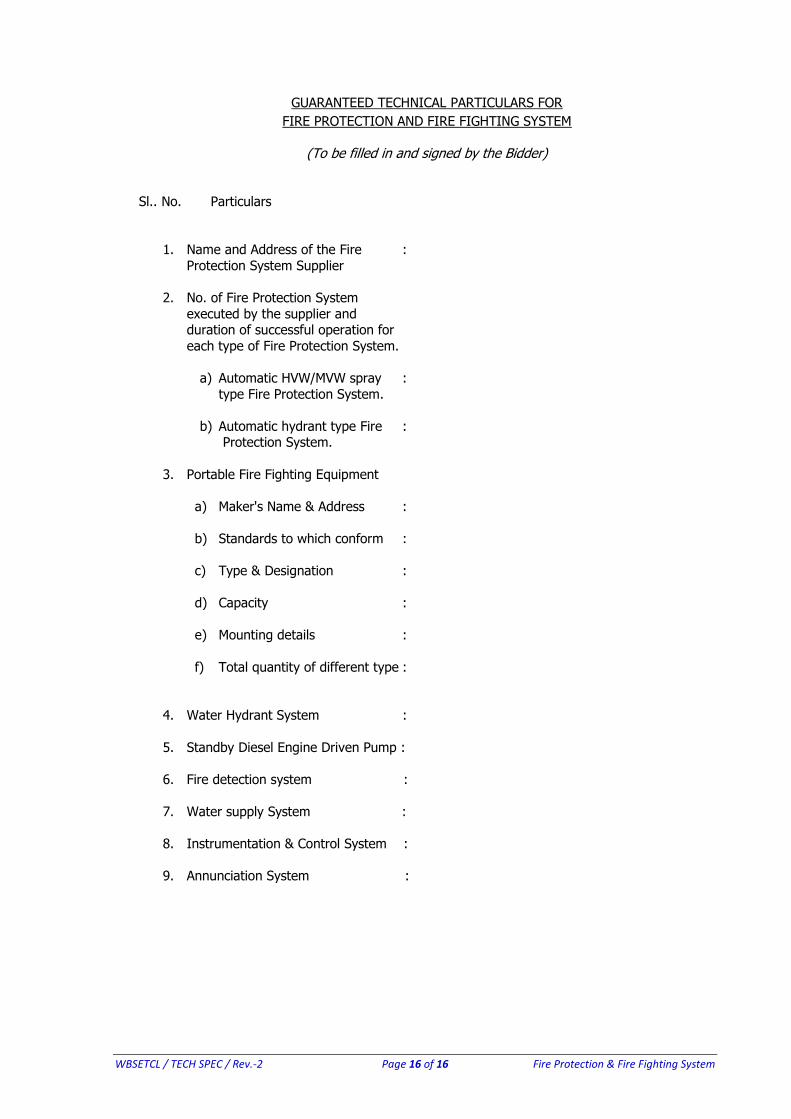
GUARANTEED TECHNICAL PARTICULARS FOR
FIRE PROTECTION AND FIRE FIGHTING SYSTEM
(To be filled in and signed by the Bidder)
Sl.. No. Particulars
1. Name and Address of the Fire :
Protection System Supplier
2. No. of Fire Protection System
executed by the supplier and duration of successful operation for
each type of Fire Protection System.
a) Automatic HVW/MVW spray :
type Fire Protection System.
b) Automatic hydrant type Fire : Protection System.
3. Portable Fire Fighting Equipment
a) Maker's Name & Address :
b) Standards to which conform :
c) Type & Designation :
d) Capacity :
e) Mounting details :
f) Total quantity of different type :
4. Water Hydrant System :
5. Standby Diesel Engine Driven Pump :
6. Fire detection system :
7. Water supply System :
8. Instrumentation & Control System :
9. Annunciation System :