
Field Programmable Gate Array-Based System-on-Chip …thescipub.com/PDF/ajassp.2010.127.139.pdf ·...
13
American Journal of Applied Sciences 7 (1): 127-139, 2010 ISSN 1546-9239 © 2010 Science Publications Corresponding Author: Ahmed Karim Ben Salem, LECAP Laboratory, Department of Electrical Engineering, National Institute of Applied Sciences and Technology (INSAT), B.P. 676, 1080 Tunis Cedex, Tunisia 127 Field Programmable Gate Array-Based System-on-Chip for Real-Time Power Process Control Ahmed Karim Ben Salem, Slim Ben Othman and Slim Ben Saoud LECAP Laboratory, Department of Electrical Engineering, National Institute of Applied Sciences and Technology (INSAT), B.P. 676, 1080 Tunis Cedex, Tunisia Abstract: Problem Statement: Nowadays Real-Time (RT) embedded control applications require not just higher performance but more flexibility as well without increasing cost and resources. Approach: In this study we presented a promising co-design and implementation of control solution. We developed flexible solution using software control algorithms coupled with an embedded RT kernel on powerful embedded processor cores, combined with reconfigurable logic and dedicated resources on the Field Programmable Gate Array (FPGA). Various architectures were compared and contrasted in terms of speed and FPGA area. Results: This fully integrated RT control system in a System-on-Chip (SoC) was applied to electric motors drive in order to enhance both flexibility and performance. Experimental results showed the feasibility and the efficiency of the approach; they demonstrate the capacity of implementing, in high-level coding, high speed and more complex control algorithms with RT constraints. Conclusions/Recommendations: Programmable SoC enabled flexible control system design. This solution can be readily applied to any control algorithm with minor hardware or software adapting to specific application requirements. Key words: Electric drive, embedded control, SoC, FPGA, RTOS, hard-core, soft-core INTRODUCTION A way to get the maximum performance from motors controlling machinery in industrial applications is to employ more efficient and sophisticated control algorithms to optimize the efficiency of motors in a factory. These new sophisticated algorithms place larger computational requirements on the processor due to the growth of complexity. Therefore, embedded Real-Time (RT) control becomes a promising research domain. The design challenge is ever how to integrate control complexities of high-sampling-frequency applications that can execute efficiently on limited embedded resources. At the same time, many control applications require updated drive control algorithms to reduce costs. Hence, there is a need to more flexible control drive platforms that enable offline system re-use with various applications. New emerging technologies in semiconductor industry offered the means to create high-performance digital components allowing implementation of more complex control applications. Recently, the System-on-Chip (SoC) (Eshraghian, 2006; Nurmi, 2007) capabilities have provided the opportunity to have a more performance digital control solution. A renewed interest is devoted to Field Programmable Gate Arrays (FPGAs) for full integration of all control functions. New FPGA technology (Rodriguez-Andina et al., 2007) containing both reconfigurable logic blocks and embedded cores becomes quite mature for high-speed power control applications. HardWare (HW) and SoftWare (SW) components interact in order to perform the given task. Such systems need a co-design expertise to build a flexible embedded controller that can execute RT closed-loop control. The power of these FPGAs has been made readily available to embedded system designers and SW programmers through the use of SW to HW tools. This ongoing work aims to apply those HW-SW architectures and tools capabilities to control applications. It is proposed a design approach that uses FPGA-based embedded processor cores to offer flexibility for the control application via programmable SW design. This enables system re-use with various control applications. At the same time, the aim is to
-
Upload
truongthien -
Category
Documents
-
view
260 -
download
0
Transcript of Field Programmable Gate Array-Based System-on-Chip …thescipub.com/PDF/ajassp.2010.127.139.pdf ·...

American Journal of Applied Sciences 7 (1): 127-139, 2010 ISSN 1546-9239 © 2010 Science Publications
Corresponding Author: Ahmed Karim Ben Salem, LECAP Laboratory, Department of Electrical Engineering, National Institute of Applied Sciences and Technology (INSAT), B.P. 676, 1080 Tunis Cedex, Tunisia
127
Field Programmable Gate Array-Based System-on-Chip for Real-Time Power
Process Control
Ahmed Karim Ben Salem, Slim Ben Othman and Slim Ben Saoud LECAP Laboratory, Department of Electrical Engineering,
National Institute of Applied Sciences and Technology (INSAT), B.P. 676, 1080 Tunis Cedex, Tunisia
Abstract: Problem Statement: Nowadays Real-Time (RT) embedded control applications require not just higher performance but more flexibility as well without increasing cost and resources. Approach: In this study we presented a promising co-design and implementation of control solution. We developed flexible solution using software control algorithms coupled with an embedded RT kernel on powerful embedded processor cores, combined with reconfigurable logic and dedicated resources on the Field Programmable Gate Array (FPGA). Various architectures were compared and contrasted in terms of speed and FPGA area. Results: This fully integrated RT control system in a System-on-Chip (SoC) was applied to electric motors drive in order to enhance both flexibility and performance. Experimental results showed the feasibility and the efficiency of the approach; they demonstrate the capacity of implementing, in high-level coding, high speed and more complex control algorithms with RT constraints. Conclusions/Recommendations: Programmable SoC enabled flexible control system design. This solution can be readily applied to any control algorithm with minor hardware or software adapting to specific application requirements. Key words: Electric drive, embedded control, SoC, FPGA, RTOS, hard-core, soft-core
INTRODUCTION
A way to get the maximum performance from motors controlling machinery in industrial applications is to employ more efficient and sophisticated control algorithms to optimize the efficiency of motors in a factory. These new sophisticated algorithms place larger computational requirements on the processor due to the growth of complexity. Therefore, embedded Real-Time (RT) control becomes a promising research domain. The design challenge is ever how to integrate control complexities of high-sampling-frequency applications that can execute efficiently on limited embedded resources. At the same time, many control applications require updated drive control algorithms to reduce costs. Hence, there is a need to more flexible control drive platforms that enable offline system re-use with various applications. New emerging technologies in semiconductor industry offered the means to create high-performance digital components allowing implementation of more complex control applications.
Recently, the System-on-Chip (SoC) (Eshraghian, 2006; Nurmi, 2007) capabilities have provided the opportunity to have a more performance digital control solution. A renewed interest is devoted to Field Programmable Gate Arrays (FPGAs) for full integration of all control functions. New FPGA technology (Rodriguez-Andina et al., 2007) containing both reconfigurable logic blocks and embedded cores becomes quite mature for high-speed power control applications. HardWare (HW) and SoftWare (SW) components interact in order to perform the given task. Such systems need a co-design expertise to build a flexible embedded controller that can execute RT closed-loop control. The power of these FPGAs has been made readily available to embedded system designers and SW programmers through the use of SW to HW tools. This ongoing work aims to apply those HW-SW architectures and tools capabilities to control applications. It is proposed a design approach that uses FPGA-based embedded processor cores to offer flexibility for the control application via programmable SW design. This enables system re-use with various control applications. At the same time, the aim is to

Am. J. Applied Sci., 7 (1): 127-139, 2010
128
achieve high computational performance for control via a combined HW design. Furthermore, control systems are commonly designed using a set of cooperating periodic sub-modules where the system should meet timing constraints to ensure a correct behavior of the closed loop controller. This can be achieved by integrating an embedded Real-Time Operating System (RTOS) to provide support for such systems and to ensure RT specification. The proposed approach ensures high-level control application coding with RT performance. It will be discussed using an application of the Direct-Current (DC) and Alternative Current (AC) motor control. It can be readily applied to any other control system application using the same steps discussed below with minor adapting. Different FPGA-based architectures are proposed and their comparative study in terms of speed and area is done. A RTOS support is integrated in the SW design flow; and a motor emulation concept is used too to validate the controllers’ functional correctness. Related work and background: High speed digital control systems: Various approaches have been studied in this embedded field in order to enhance industrial control systems performance (Monmasson and Cirstea, 2007). The new requirements of power electronic control systems soon reveal that digital solutions based purely on microprocessors can not achieve the required specifications. These requirements exceed the capability of most common microcontrollers to execute the new complex algorithm functions running in SW. The advent of the latest generation of signal processors or DSP has made it much less simpler to implement such algorithms (Hadiouche et al., 2006). However, standalone Digital Signal Processors (DSPs) can no longer answer this new generation of control applications that require not just higher performance but more flexibility as well without increasing cost and resources. A few years ago, new flexible platforms based on several common interconnected devices in the same board: such as an FPGA or an Application Specific Integrated Circuit (ASIC) to implement HW tasks with a general processor or DSP for SW tasks (Aguirre et al., 2005), could be an alternative solution ensuring higher performance and more flexibility (Bueno et al., 2009). However, the use of mixed devices adds cost and introduces complex functional partitioning or communication latencies. Nowadays, thanks to novel gate-array integration levels and cost, SoC solution based on single programmable device is considered as an appropriate solution (Ben Saoud et al., 2005) in order to boost
performances of controllers. Commonly used SoC devices are FPGA chips. Several works have been conducted in recent years using these devices for high-speed control (Chan et al., 2007; De Castro et al., 2007; Idkhajine et al., 2009) and they have proved efficiency of these highly reconfigurable solutions. A comparison between DSP and FPGA-based control capabilities has been carried out in (Fratta et al., 2004), it has been demonstrated how FPGA-based digital control properties are better than DSP ones for any comparative term. But the last FPGA-based designs and modeling techniques lack flexibility since these HW-dedicated implementations are fixed with no possibility of upgrade or use with another algorithm. So the FPGA core-based approach, interconnecting pre-designed HW Intellectual Property (IP) cores around the reconfigurable logic blocks of the component and programmable embedded processors on the same chip has been proposed as a solution to ensure more flexibility. It has been recently applied, in few works, to Mechatronic systems design (Kung et al., 2009; Astarloa et al., 2009). Moreover, the implementation of digital control systems and RT systems belong together and they should be connected in the design process. The closed loop control system is the most common type of control that requires RT execution. Embedded real-time control systems: A complex control system involves sub-systems with different dynamics which must be further coordinated. Some parts of the control algorithm, e.g., controlling slow modes, can be executed slower than the one used for fast modes. The control system can be divided into subtasks that operate at different update rates depending on the available bandwidth. This can be achieved by a RT system that satisfies these various processing speeds. A RT system (Gambier, 2004) poses stringent requirements on precisely time-triggered synchronized actions in feedback loops. With RTOS, also called a RT kernel, there has been a tendency to provide facilities for creating several tasks within the same program to have faster task switch and unrestricted access to shared memory. A RTOS allows applications to be easily designed and expanded in the sense that it simplifies the design process by splitting the application code into separate tasks, so functions can be added without requiring major changes to the SW. Multitasking allows a modularized solution and increasing code reuse. So application’s performance is enhanced, regardless of its size and complexity. Nowadays, there has been an interest in enabling multiple embedded control applications to share a
Am. J. Applied Sci., 7 (1): 127-139, 2010
129
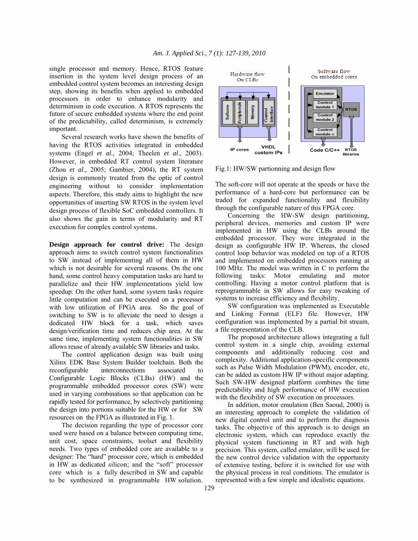
single processor and memory. Hence, RTOS feature insertion in the system level design process of an embedded control system becomes an interesting design step, showing its benefits when applied to embedded processors in order to enhance modularity and determinism in code execution. A RTOS represents the future of secure embedded systems where the end point of the predictability, called determinism, is extremely important. Several research works have shown the benefits of having the RTOS activities integrated in embedded systems (Engel et al., 2004; Theelen et al., 2003). However, in embedded RT control system literature (Zhou et al., 2005; Gambier, 2004), the RT system design is commonly treated from the optic of control engineering without to consider implementation aspects. Therefore, this study aims to highlight the new opportunities of inserting SW RTOS in the system level design process of flexible SoC embedded controllers. It also shows the gain in terms of modularity and RT execution for complex control systems. Design approach for control drive: The design approach aims to switch control system functionalities to SW instead of implementing all of them in HW which is not desirable for several reasons. On the one hand, some control heavy computation tasks are hard to parallelize and their HW implementations yield low speedup. On the other hand, some system tasks require little computation and can be executed on a processor with low utilization of FPGA area. So the goal of switching to SW is to alleviate the need to design a dedicated HW block for a task, which saves design/verification time and reduces chip area. At the same time, implementing system functionalities in SW allows reuse of already available SW libraries and tasks. The control application design was built using Xilinx EDK Base System Builder toolchain. Both the reconfigurable interconnections associated to Configurable Logic Blocks (CLBs) (HW) and the programmable embedded processor cores (SW) were used in varying combinations so that application can be rapidly tested for performance, by selectively partitioning the design into portions suitable for the HW or for SW resources on the FPGA as illustrated in Fig. 1. The decision regarding the type of processor core used were based on a balance between computing time, unit cost, space constraints, toolset and flexibility needs. Two types of embedded core are available to a designer: The “hard” processor core, which is embedded in HW as dedicated silicon; and the “soft” processor core which is a fully described in SW and capable to be synthesized in programmable HW solution.
Fig.1: HW/SW partionning and design flow The soft-core will not operate at the speeds or have the performance of a hard-core but performance can be traded for expanded functionality and flexibility through the configurable nature of this FPGA core. Concerning the HW-SW design partitioning, peripheral devices, memories and custom IP were implemented in HW using the CLBs around the embedded processor. They were integrated in the design as configurable HW IP. Whereas, the closed control loop behavior was modeled on top of a RTOS and implemented on embedded processors running at 100 MHz. The model was written in C to perform the following tasks: Motor emulating and motor controlling. Having a motor control platform that is reprogrammable in SW allows for easy tweaking of systems to increase efficiency and flexibility. SW configuration was implemented as Executable and Linking Format (ELF) file. However, HW configuration was implemented by a partial bit stream, a file representation of the CLB. The proposed architecture allows integrating a full control system in a single chip, avoiding external components and additionally reducing cost and complexity. Additional application-specific components such as Pulse Width Modulation (PWM), encoder, etc, can be added as custom HW IP without major adapting. Such SW-HW designed platform combines the time predictability and high performance of HW execution with the flexibility of SW execution on processors. In addition, motor emulation (Ben Saoud, 2000) is an interesting approach to complete the validation of new digital control unit and to perform the diagnosis tasks. The objective of this approach is to design an electronic system, which can reproduce exactly the physical system functioning in RT and with high precision. This system, called emulator, will be used for the new control device validation with the opportunity of extensive testing, before it is switched for use with the physical process in real conditions. The emulator is represented with a few simple and idealistic equations.

Am. J. Applied Sci., 7 (1): 127-139, 2010
130
Software design: The designed system, consisting of closed loop controllers running on top of an embedded RTOS on the same processor, meets timing constraints like periods and latencies, which can be expressed as deadlines. The RTOS task manager is composed by the dispatcher and the scheduler. The dispatcher carries out the context switch and the scheduler has the function of selecting the task, which will obtain the processor as next. RT systems need special algorithms to schedule a set of tasks. In RT control scheduling, theory priorities are principally applied to control loop periodic activities. So it is opted to fixed priority based preemption mechanism. In this scheduling, each task has a fixed static priority which is computed pre-run time. The runnable tasks are executed in the order determined by their priorities. The scheduler should be triggered by a timer generating interrupts at a fixed time interval called the time tick and fixed at 100 µs. Hence, the system requires a scheduling interrupt handler routine. In the SW flow (Fig. 1), the RTOS is structured as a library. So the user application source files must link with the RTOS to access its functionality. The final image linking the RTOS to the application becomes an ELF file that can be downloaded, bootloaded and debugged as with any other ELF file for stand-alone program. The most important consideration when choosing a RTOS for control applications is reliable performance. So, to find the right RTOS for the control applications, many features must be considered such as: control algorithm integration, robust scheduling algorithms, fast context-switch, HW and I/O support, code footprint. µC-OS/II has been chosen among various existing RTOSes due to the following interesting features: µC-OS/II (Labrosse, 2002) has been widely used in several applications (Engel et al., 2004) such as safety-critical systems, including avionics RTCA DO-178B where failure could result in catastrophic loss of the aircraft and Level A Class III medical devices where failure could result in loss of life for the patient (Vargas, 2006). µC-OS/II is a highly portable, very scalable, RT multitasking kernel. µC-OS/II is portable since it has been written in ANSI C and contains a small portion of assembly language code to adapt it to different processor architectures. µC-OS/II has been ported to different processor architectures, among them, the PowerPCTM 405 (PPC405) and Microblaze. In order to achieve timeliness, priority scheduling is supported. Furthermore, preemption is supported in order to perform a time-critical function.
µC-OS/II is a small RT kernel with a small memory footprint of about 20kB for space-constrained embedded designs. It is easily scaled because of the modular nature of the source code. Moreover, µC-OS/II is freeware for academic purpose and a well-documented source code. This makes it a good candidate for this study. Hardware design: Platform: ML-310 evaluation board: The development platform consists of Xilinx ML310 board (Xilinx Inc., 2009) with a SoC FPGA. Its Xilinx Virtex-II Pro XC2VP30 FPGA combines more than 30,000 logic cells and dual IBM PPC405 hard-core processors on a single chip. The large amount of peripherals offers a variety of different interfaces. The Virtex II Pro can be partially and dynamically reconfigured. The Xilinx EDK 7.1i environment (Xilinx Inc., 2009) provides the tools and libraries to integrate the PPC405 cores on chip, soft Microblaze cores, IBM CoreConnect buses and customizable peripherals to design Multi-Processor SoC (MPSoC) micro-architectures. Design contents: The constructed platforms utilize both hard-coded PPC405 and soft-core Microblaze processors (Xilinx Inc., 2009). Both processors offer some unique benefits through circuitry dedicated to interfacing with on-chip peripherals in the FPGA fabric. The embedded PPC405 core is a 32 bit Harvard architecture processor with integrated functional units such as cache unit (separate 16 KB instruction and data caches). Most instructions execute in a single cycle (Xilinx Inc., 2005). Considering that PPC405 has instruction and data cache built into the silicon of the hard processor, so enabling the cache is almost always a performance advantage for the design. The Microblaze core is a 3 stage pipeline 32 bit RISC Harvard architecture with a rich instruction set optimized for embedded applications (Xilinx Inc., 2010). There are different processor versions from which to choose: the smaller three-stage Microblaze v4.0 core is ideal for cost-focused applications. Unlike PPC405, the Microblaze cache architecture is not dedicated silicon. Cache controllers are selectable parameters in the Microblaze configuration and when they are included, the cache memory is built from Block RAM (BRAM). Therefore, enabling the cache consumes BRAM that could have otherwise been used for local memory. The IBM core-connect bus architecture enables the compliant IP cores to integrate with the previous processor blocks. It provides various buses for interconnection of hard and soft IP cores.

Am. J. Applied Sci., 7 (1): 127-139, 2010
131
For Microblaze, On-chip Peripheral Bus (OPB) is used to connect larger external memory. But it presents less performance than implementations using Local Memory Bus (LMB) interface. LMB is designed to allow fast memory access. Thus, Microblaze can be configured to cache instructions or data only over the OPB interface to enhance system performance (Gambier, 2008). Therefore, for comparing the performance of the PPC405 hard-core with the Microblaze soft-core with cache enabled, the case of OPB memory controller for the Microblaze versus PLB controller for the PPC405 should be considered. For the designed architectures, the OPB is used to connect slow peripherals that are the following: • RS232 serial channel, connected to an UART
peripheral, used for communication between an external user interface and the platform
• General Purpose Input Output (GPIO) peripheral, used for time execution measurements on logic analyzer
• Timer peripheral, used to synchronize the RT scheduling of the RTOS
• A second timer, used for applications profiling • Interrupt controller peripheral, used to manage
multiple interrupts Both next subsections describe in details the FPGA embedded system design block diagrams depending on the complexity of the control case study. The FPGA architectures are straightforward and can be applied to any motor drive application. Monoprocessor architecture: Figure 2 presents the different FPGA embedded system components used in the HW design. Both architectures of Fig. 2 are based on a single processor. This monoprocessor architecture is suitable for a simple closed loop motor control implementation. In the first architecture of Fig. 2a, the hard-core PPC405 is used. It is connected to its own BRAM memory via a fast PLB. PPC405 has only the PLB bus interface and therefore OPB devices cannot directly connect to the processor. Consequently, the OPB is connected to the PLB through PLB-to-OPB bridge. In the second architecture of Fig. 2b, the soft-core Microblaze is used. It is connected to its BRAM memory via a LMB. Dual-processor architecture: This architecture is dedicated to a more complex control algorithm. The emulator functionality, previously implemented on the same processor used for controllers, should be ported on a second processor core. The goal of locking a separate processor core to the specific motor emulation
task is to obtain more predictability which allows motor emulator working on RT conditions at its optimal time period. On the other hand this configuration aims to reduce the context switch latencies for processor supporting controllers.
(a)
DLMB BRAMController
UART
SOPB
InterruptController
SOPB
Timers1,2
SOPB
GPIO
SOPB
PortAPortBSLMB
OPB
Master connectionSlave connection
Microblazev4.0
IOPBDOPB
ILMBDLMB
SLMB
ILM
B
ILMB BRAMController
BRAM Block
DLM
B
(b) Fig. 2: Hardware design block diagram. (a) PPC405
based; (b) Microblaze based
Fig. 3: MPSoC based design block diagram

Am. J. Applied Sci., 7 (1): 127-139, 2010
132
Table 1: Processing speeds and priority Task Time period Processing priority Emulator 100 us 1 PI current controller 300 us 2 PI speed controller 20 ms 3
Fig. 4: Control loop diagram for DC motor drive So, an MPSoC architecture based on a dual-processor (Fig. 3) has been used for implementation. The two embedded processors communicate between each others via a small shared BRAM. Each processor has its own BRAM to implement its assigned portion of code. Embedded control case studies: A significant number of industrial applications benefit greatly from variable speed operation. For this application case study, two standard electric motor drives have been used: Firstly, a simple case of a DC motor driven by Proportional Integral (PI) controllers. Secondly, a generalization of the first study to a common complex AC machinery drive consisting of an induction motor driven by a FOC. For the second case-study, the aim of this conducted experiment is to analyze the capability of SoC to run complex and sophisticated algorithms executed in SW respecting RT performance. DC-motor drive: DC motor control systems are simple control applications commonly used for motion control applications. PI Derivative (PID) control is the most applied control strategy around the world (Gambier, 2008) usually for DC Motor. Generally, the PID controller is formulated in the continuous-time domain. Therefore, to implement the controller as a computational algorithm, the controller equations have been discretized. For this case study, the DC motor control loop based on two PI controllers and a process emulator is illustrated in Fig. 4. Table 1 details the sample period of the different components. Both PI controllers have been interfaced with the motor emulator through a very fast circuitry on a single
embedded processor using clearly-defined run-time behavior. Besides, by providing the high CPU computing power, SoC makes the use of DC machines obsolete in terms of power conversion efficiency and system reliability, when compared with AC machines. So a FOC for AC motor is presented in the next subsection to highlight the power of the proposed approach. FOC for induction motor: FOC constitutes a fundamental concept behind the modern technology of high-performance vector-controlled drive systems with three-phase AC motors. The FOC was introduced along time ago (Blaschke, 1972) allowing high torque at very low speed. The properties of these controllers are well known and have been presented by several authors (Trzynadlowski, 1993). They are not the subject matter of this contribution. Instead of that, it is looked at the efficient implementation of this advanced machine drive algorithm using FPGAs. Figure 5 presents the scheme of FOC principle. The key idea of the FOC algorithm lays in performing basic transformations and rotations on the state variables of the asynchronous machine, in such a way that the resulting machine becomes equivalent to an easy to control DC motor. Indeed, the principle of the FOC method is to transform the equations of the three-phase induction motor in order to allow a separate control of both flux and torque. It senses 3-phase motor current is1, is2 and is3 and transforms into 2 variables, torque current (Iq) and flux current (Id), so that it simplifies the torque Ce control (1):
( )Ce p M Isq Ird Isd Irq= ⋅ ⋅ − ⋅ (1) Where: Ce = Electromagnetic torque P = Pole pairs number M = Mutual inductance Isd, Isq = Stator flux current, stator torque current Ird, Irq = Rotor flux current, rotor torque current Φr = Rotor flux ρ = Rotor flux position So, as showing in Fig. 5, the control device consists of a set of sub-controllers. There is two separate current control loops. Each loop consists of several control elements: Vector rotator, Park transformation, PI, PWM and current sensing that are essential in each closed loop current control.

Am. J. Applied Sci., 7 (1): 127-139, 2010
133
Fig. 5: Induction motor control loop using FOC Moreover, once the torque is controlled, an external control loop could be added which is the speed controller block. The latest can also be a slow mode PI regulator; it produces the torque command Cemref to run the machine at a given speed (the speed set-point Ωref). Considering the complex general structure of this FOC algorithm, demanding a certain digital power computing (e.g., Park transformations, trigonometric functions manipulation, integration, regulation, etc.), it should be embedded using the dual-processor architecture of Fig. 3 to achieve high-speed performance. So, the emulator has been implemented separately on the processor PPC1 to track the real functioning of the set Inverter/AC Motor. Whereas, the control device has been implemented on the processor PPC0. The closed control loop behavioral has been modeled by SW tasks on top of a RTOS in both processors. The PI currents SW task consists of Clarke/Park transformations, the flux estimator, the rotor flux position computing and all the PI current controllers (torque and flux). For the motor emulator, the set Inverter/AC Motor model has been partitioned in two sub-modules: electric and mechanic computing.
RESULTS
During the entire validation process, the system was tested using the ML310 board with the Virtex-II Pro FPGA. The final bit stream generated by the EDK Xilinx environment has been used to program the FPGA and the system has been tested with the SW sources running on the HW platform. Time measurements have been carried out with a logic analyzer connected to the system bus via the GPIO component. The measurements were done using GPIO SW functions with set and reset of the different pins. A PC-based user interface allows easy data acquisition for different control variables of the system and performance analysis. The PC communicates with the test board through the UART serial connection. RTOS Benchmark: Every RT kernel has a heart beat, which is configured with an interval timer using a RT interrupt clock as a HW peripheral device. So the HW timer periodically interrupts the processor to invoke the scheduler, it allows task control on a timed basis using a tick routine. The best tick rate for the µC-OS/II is 100 µs.
Am. J. Applied Sci., 7 (1): 127-139, 2010
134
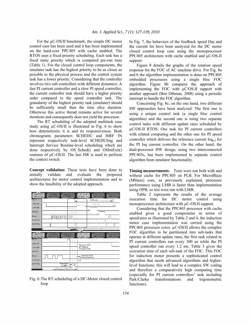
For the µC-OS/II benchmark, the simple DC motor control case has been used and it has been implemented on the hard-core PPC405 with cache enabled. The RTOS uses a fixed-priority scheduling. Each task has a fixed static priority which is computed pre-run time (Table 1). For the closed control loop components, the emulator task has the highest priority to be as closer as possible to the physical process and the control system task has a lower priority. Considering that the controller involves two sub-controllers with different dynamics: A fast PI current controller and a slow PI speed controller, the current controller task should have a higher priority order compared to the speed controller task. The granularity of the highest priority task (emulator) should be sufficiently small than the time slice duration. Otherwise this active thread remains active for several iterations and consequently does not yield the processor. The RT scheduling of the adopted multitask case study using µC-OS/II is illustrated in Fig. 6 to show how deterministic it is and its responsiveness. Both chronograms parameters SCHEDU and ISRF IN represent respectively task-level SCHEDUling and Interrupt Service Routine-level scheduling which are done respectively by OS_Sched() and OSIntExit() routines of µC-OS/II. The last ISR is used to perform the context switch. Concept validation: These tests have been done to initially validate and evaluate the proposed architectures for motor control implementation and to show the feasibility of the adopted approach.
Fig. 6: The RT scheduling of a DC-Motor closed control
loop
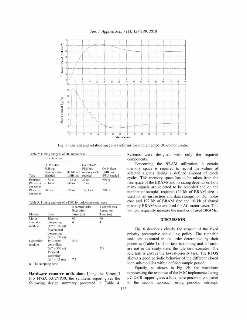
In Fig. 7, the behaviors of the feedback speed Ωm and the current Im have been analyzed for the DC motor closed control loop case using the monoprocessor PPC405 architecture with cache enabled and µC/OS-II support. Figure 8 details the graphs of the rotation speed response for the FOC of AC machine drive. For Fig. 8a and b the algorithm implementation is done on PPC405 embedded processors using a single bloc FOC algorithm. Figure 8b compares the approach of implementing the FOC with µC/OS-II support with another approach (Ben Othman, 2008) using a periodic interrupt to handle the FOC algorithm. Concerning Fig. 8c; on the one hand, two different SW approaches have been analyzed: The first one is using a unique control task (a single bloc control algorithm) and the second one is using two separate control tasks with different update rates scheduled by µC/OS-II RTOS: One task for PI current controllers with related computing and the other one for PI speed controller which delivers the reference current Isqref for the PI Isq current controller. On the other hand, the dual-processor HW design, using two interconnected PPC405s, has been implemented to separate control algorithm from emulator functionality.
Timing measurements: Tests were run both with and without cache for PPC405 on PLB. For MicroBlaze (Mblaze) core, as previously explained, processor performance using LMB is faster than implementation using OPB, so test were run with LMB. Table 2 represents the results of the average execution time for DC motor control using monoprocessor architecture with µC-OS/II support. Considering that the PPC405 processor with cache enabled gives a good compromise in terms of speed/area as illustrated by Table 2 and 4, the induction motor case implementation was carried using the PPC405 processor cores. µC-OS/II allows the complex FOC algorithm to be partitioned into sub-tasks that operate at different update rates, the first task related to PI current controllers run every 300 us while the PI speed controller run every 1.2 ms. Table 3 gives the execution time of each sub-task of the FOC. This FOC for induction motor presents a sophisticated control algorithm that needs advanced algorithms and higher-level functions; this will lead to a complex SW coding and therefore a comparatively high computing time (especially for PI current controllers’ task including Park/Clarke transformations and trigonometric functions).
Am. J. Applied Sci., 7 (1): 127-139, 2010
135
Fig. 7: Current and rotation speed waveforms for implemented DC-motor control
Table 2: Timing analysis of DC-motor case Execution time -------------------------------------------------------------------------- On PPC405 On PPC405 PLB bus PLB bus On Mblaze memory cache On Mblaze memory cache LMB bus Task disabled LMB bus enabled FPU enabled Emulator ~138 us ~128 us 22 us 900 ns PI current ~114 us ~88 us 16 us 1 us controller PI speed ~85 us ~78 us 12-14 us 700 ns controller
Table 3: Timing analysis of a FOC for induction-motor case 2 control tasks 1 control task Execution Execution Module Task Time (us) Time (us) Motor Electric 90 90 emulator computing 4 4 module (te* = 100 us) Mechanical computing (te* = 100 us) Controller PI Current 206 module controllers (te* = 300 us) 229 PI speed controller (te* = 1.2 ms) 7.7 te: The sampling perio
Hardware resource utilization: Using the Virtex-II Pro FPGA XC2VP30, the synthesis report gives the following design summary presented in Table 4.
Systems were designed with only the required components. Concerning the BRAM utilization, a certain memory space is required to record the values of selected signals during a defined amount of clock cycles. This memory space has to be taken from the free space of the BRAMs and its sizing depends on how many signals are selected to be recorded and on the number of samples required (64 kb of BRAM size is used for all instruction and data storage for DC motor case and 192 kb of BRAM size and 16 kb of shared memory BRAM size are used for AC motor case). This will consequently increase the number of used BRAMs.
DISCUSSION
Fig. 6 describes clearly the respect of the fixed priority preemptive scheduling policy. The runnable tasks are executed in the order determined by their priorities (Table 1). If no task is running and all tasks are not in the ready state, the idle task executes. The idle task is always the lowest-priority task. The RTOS allows a good periodic behavior of the different closed loop sub-modules within defined sample period. Equally, as shown in Fig. 8b, the waveform representing the response of the FOC implemented using µC-OS/II support gives a little more precision compared to the second approach using periodic interrupt.

Am. J. Applied Sci., 7 (1): 127-139, 2010
136
(a)
(b)
(c)
Fig. 8: Comparasion between different AC-motor FOC behaviors using various HW-SW design concepts. (a)
Analysis of different speed references; (b) Analysis of one controller SW architecture with two periodic SW approaches; (c) Analysis of different HW/SW architectures with μC-OS/II support and cache enabled

Am. J. Applied Sci., 7 (1): 127-139, 2010
137
Table 4: Device utilization summary Type of architecture configuration 1 Mblaze (%) 1 Mblaze with FPU (%) 1 PPC405 (%) 2 PPC405 (%) Number of occupied Slices 1,704 out of 13,696: 12 2,396 out of 13,696: 17 1,583 out of 13,696: 11 3089 out of 13,696: 22 Number of used BRAMs 32 out of 136: 23 32 out of 136: 23 32 out of 136: 23 104 out of 136: 76 Number of multipliers 3 out of 136: 2 7 out of 136: 5 0 out of 136: 0 0 out of 136: 0 (MULT18X18s) Total equivalent gate 4,287,966 out of 4,316,485 out of 2,158,755 out of 6,928,698 out of count for design 30,000,000: 14.2 30,000,000: 14.3 30,000,000: 7 30,000,000: 23 Additionally, the second approach assumes that an interrupt handler routine and a HW timer must be assigned for every control sub-bloc. If the FOC algorithm will be partitioned in other sub-blocs, they will need several HW timers that will increase FPGA area cost (a HW timer component consumes about 15% of the total number of occupied Slices). While the first approach needs only a unique HW timer for µC/OS-II tick routine. Hence, RTOS introduced more predictability to control system response without increasing area cost. Table 3 confirms the gain with using RTOS. It demonstrates that separating the control task into two separating tasks with different dynamics gives more speed performance (206+7.7 us instead of 229 us). This is also noted from graphs of Fig. 8c using two controllers versus others using one controller. The RTOS plays a major role in tasks scheduling and control loops synchronizing. On the other hand, the motor control good functioning is verified in Fig. 7and 8. Figure 7a depicts that the rotation speed Ωm of the DC motor is able to follow the speed reference Ωmref set to 100 rad sec−1, with good dynamics and relatively low error, while the good motor current behavior can be seen in Fig. 7b. Figure 8a shows that the rotation speed of the AC motor can track any fixed reference with good dynamic behavior. In Fig. 8b and c, the different rotation speed graphs reach exactly the speed reference assigned initially as 100 rad sec−1 and modified to -100 rad sec−1 at 1s time. Hence, these experimental results validate successfully both motor control implementations with the proposed SoC designs. Furthermore, concerning HW architectures comparison in terms of speed/area, we have obtained the following: Firstly, the study in Table 2 highlights the great benefit of using cache in the design of PPC405 processor. The system goes faster when the cache is enabled in this system design. This confirms the fact that enabling the cache is almost always a performance advantage. Moreover, assuming that Mblaze can not be configured to cache instructions or data over the LMB interface, the timing results of Table 2 confirm that the
control drive implementation gives more speed performance on the hard-core PPC405 with cache enabled than on the soft-core Mblaze without enabling the Floating Point Unit (FPU). It is equally noted from Table 4 that the design based on a single PPC405 consumes less logic area resources (7% of total gate count) than the one using a single Mblaze (14% of total gate count). This is to be expected, as the Mblaze soft-core is built from logic units and it uses about 6% of total occupied slices. While the PPC405 hard-core is part of the FPGA fabric with no resource usage which reduces the available area for logic. Therefore, the use of PPC405 with cache enabled presents better performance compromise than using Mblaze processor. Secondly, Table 2 shows that Mblaze processor running with the FPU HW module gives the best speed performance and achieves high sampling frequency for controller execution. Indeed, enabling the FPU feature allows accelerating the arithmetic using real numbers. However, this FPU consumes additional FPGA area (about 5% of total occupied slices) as can be seen in Table 4. This can be considered as a space restriction for more complex design applying a multiprocessor architecture with several standard and custom HW IPs. Finally, Fig. 8c confirms that the dual PPC405 architecture gives more speed performance than the single PPC405 architecture. It offers more predictability for the motor emulator, allowing it to work on RT conditions. It is also interesting to note that the overall HW summary of Table 4 shows low HW costs for such an implementation (about 23% of total gate count in the worst case of a dual-processor design). So assuming that there are available resources on the FPGA, it is still better to map certain time-critical or speed sensitive tasks such as trigonometric computing onto the FPGA logic.
CONCLUSION In this study, it is contrasted different FPGA-based architectures capabilities. These architectures were designed to serve in two electrical motor control case studies and were successfully validated. They have confirmed the feasibility of such implementations.
Am. J. Applied Sci., 7 (1): 127-139, 2010
138
Practical experiments on DC motor control SoC implementation have shown the benefits of using hard-core embedded processor with cache enabled for handling embedded control system with good speed performance without increasing FPGA area. Experimental results with AC motor case study have demonstrated how new SoC technology enables designers to implement advanced machine drive algorithm including complex computing, such as FOC for induction motors, with good precision, low FPGA area usage and respecting RT constraints. The study highlight successfully that the use of a RTOS in handling embedded control tasks accelerates SW implementations and ensures more determinism and modularity for embedded closed loop control systems. The FPGA-based designed control system is able to support both HW and SW customization. It allows inserting additional interfaces and controllers as SW tasks to enable system re-use with other control applications. This fully SoC integrated RT control system provided not only lower cost and high speed execution, but it also accelerated the development schedule by simplifying the HW porting effort and enhancing product flexibility. Thus make the designed control system long-lived. Finally, when trying to design the embedded control system, it has been met various sorts of quantifiable goals. But it can be concluded that the control speed sensitive tasks should always be implemented in HW to respond to high sampling frequencies. This can be performed in the flexible platform by adding custom HW IP cores.
REFERENCES Aguirre, M.A., J.N. Tombs, V.B. Lecuyer, J.L. Mora
and J.M. Carrasco et al., 2005. Microprocessor and FPGA interfaces for in-system co-debugging in field programmable hybrid systems. Microproc. Microsyst., 29: 75-85. DOI: 10.1016/j.micpro.2004.06.009
Astarloa, A., J. Lázaro, U. Bidarte, J. Jiménez and A. Zuloaga, 2009. FPGA technology for multi-axis control systems. Mechatronics, 19: 258-268. DOI: 10.1016/j.mechatronics.2008.09.001
Ben Saoud, S. and J.C. Hapiot, 2000. Parallel architectures applied to real time emulation. Proceedings of the 26th IEEE International Conference on Industrial Electronics, Oct. 22-28, Nagoya, Japan, pp: 1719-1724, DOI: 10.1109/IECON.2000.972535
Ben Saoud, S., A. Gerstlauer and D.D. Gajski, 2005. Codesign methodology of real-time embedded controllers for electromechanical systems. Am. J. Applied Sci., 2: 1331-1336. DOI: 10.3844/ajassp.2005.1331.1336
Ben Othman, S., M. Ghrissi, A.K. Ben Salem and S. Ben Saoud, 2008. FPGA HardCore single processor implementation of RT control applications. Proceeding of the 3rd International Conference Design and Technology of Integrated Systems in nanoscale era, Mar. 25-28, IEEE Press, Tozeur, Tunisia, pp: 1-4. DOI: 10.1109/DTIS.2008.4540272
Blaschke, F., 1972. The principle of field orientation as applied to the new transvektor closed loop control system for rotating-field machines. Siemens Rev., 34: 217-220.
Bueno, E.J., Ã. Hernandez, F.J. Rodriguez, C. Giron and R. Mateos et al., 2009. A DSP- and FPGA-based industrial control with high-speed communication interfaces for grid converters applied to distributed power generation systems. IEEE Trans. Ind. Elect., 56: 654-669. DOI: 10.1109/TIE.2008.2007043
Chan, Y.F., M. Moallem and Wang Wei, 2007. Design and implementation of modular FPGA-based PID controllers. IEEE Trans. Ind. Elect., 54: 1898-1906. DOI: 10.1109/TIE.2007.898283
De Castro, R.P., H.S. Oliveira, J.R. Soares, N.M. Cerqueira and R.E. Araujo, 2007. A new FPGA based control system for electrical propulsion with electronic differential. Proceeding 12th European Conference Power Electronics and Applications, Sept. 2-5, Aalborg, Danmark, pp: 1-10. DOI: 10.1109/EPE.2007.4417434.
Eshraghian, K., 2006. SoC emerging technologies. Proc. of IEEE. JPROC, 94. DOI: 1197-1213. 10.1109/JPROC.2006.873615
Engel, F., I. Kuz, S.M. Petters and S. Ruocco, 2004. Operating systems on SoCs: A good idea? Proceeding of the Embedded Real-Time Systems Implementation (ERTSI) Workshop, Lisbon, Porgutal, Dec. 2004. DOI: 10.1.1.59.5431
Fratta, A., G. Griffero and S. Nieddu, 2004. Comparative analysis among DSP and FPGA-based control capabilities in PWM power converters. Proceeding of the 30th Annual Conference of IEEE, IECON 04, IEEE press, Busan, Korea, Nov. 2004, pp: 257-262. DOI: 10.1109/IECON.2004.1433319
Gambier, A., 2004. Real-time control systems: A tutorial. Proceeding of the IEEE, 5th Asian Control Conference, July 2004, Melbourne, Australia, pp: 1024-1031.

Am. J. Applied Sci., 7 (1): 127-139, 2010
139
Gambier, A., 2008. Digital PID controller design based on parametric optimization. Proceeding of the IEEE International Conference, Control Applications (CCA 08), Sept. 2008, Texas, USA, pp: 792-797. DOI: 10.1109/CCA.2008.4629671
Hadiouche, D., L. Baghli and A. Rezoug, 2006. Space-vector PWM techniques for dual three-phase AC machine: Analysis, performance evaluation and DSP implementation. IEEE Trans. Ind. Appli., 42: 1112-1122. DOI: 10.1109/TIA.2006.877737
Idkhajine, L., E. Monmasson, M.W. Naouar, A. Prata and K. Bouallaga, 2009. Fully Integrated FPGA-Based controller for synchronous motor drive. IEEE Trans. Ind. Elect., 56: 4006-4017. DOI: 10.1109/TIE.2009.2021591
Kung, Y.S., R.F. Fung and T.Y. Tai, 2009. Realization of a motion control IC for $X{-}Y$ table based on novel FPGA technology. IEEE Trans. Ind. Elect., 56: 43-53. DOI: 10.1109/TIE.2008.2005667
Labrosse, J.J., 2002. MicroC/OS-II: The Real-Time Kernel. 2nd Edn., CMP Books, ISBN-10: 1-57820-103-9 2002, p: 648.
Monmasson, E. and M.N. Cirstea, 2007. FPGA design methodology for industrial control systems-a review. IEEE Trans. Ind. Elect., 54: 1824-1842. DOI: 10.1109/TIE.2007.898281
Nurmi, J., 2007. Processor design: System-on-chip computing for ASICs and FPGAs. Kindle Edn., Springer. ISBN: 978-1-4020-5529-4, pp: 528.
Rodriguez-Andina, J.J., M.J. Moure and M.D. Valdes, 2007. Features, design tools and application domains of FPGAs. IEEE Trans. Ind. Elect., 54: 1810-1823. DOI: 10.1109/TIE.2007.898279
Theelen, B.D., A.C. Verschueren , V. V. Reyes Suarez, M.P.J. Stevens and A.A Nunez, 2003. Scalable single-chip multi-processor architecture with on-chip RTOS kernel. J. Syst. Architecture, 49: 619-639. DOI: 10.1016/S1383-7621(03)00101-2
Trzynadlowski, A.M., 1993. The Field Orientation Principle in Control of Induction Motors. 1st Edn., Springer. ISBN: 13: 978-0792394204, pp: 280.
Vargas, F., L. Piccoli, A. Alecrim, M. Moraes and M. Gama, 2006. Summarizing a time-sensitive control-flow checking monitoring for multitask System-on-Chip. Proceeding of the IEEE International Conference, Field Programmable Technology (FPT 06), Dec. 13-15, Bankok, India, pp: 249-252. DOI: 10.1109/FPT.2006.270320.
Xilinx Inc., 2009. Products and services. Xilinx. Xilinx Inc., 2005. MicroBlaze Processor Reference
Guide. Xilinx Xilinx Inc., 2010. PowerPC Processor Reference Guide.
Xilinx. Zhou, P., J. Xie and L. Wang, 2005. Co-design of
embedded real-time control systems: A feedback scheduling approach. Proceeding of the 11th Joint International Computer Conference, Nov. 10-12, World Scientific, Chonqing, China, pp: 316-319. DOI: 10.1142/9789812701534_0070


![Architecture of field-programmable gate arrays ...arantxa.ii.uam.es/~die/[Lectura FPGA Architecture] Architecture of... · Architecture of Field-Programmable Gate Arrays JONATHAN](https://static.fdocuments.in/doc/165x107/5f41b9382d13750b786f03bd/architecture-of-field-programmable-gate-arrays-dielectura-fpga-architecture.jpg)


