Features and Benefits - SwitchDoc
22
BC24 0600-BIGCIRCLE32-DSBT Product Specification Introduction The BC24 is an amazing display. With 24 programmable Pixel RGBW LEDs and a very fast processor you can create very interesting displays. You can add more Pixel strings, other displays and many sensors using the Grove connectors. The processor on the BC24 is an ESP32 which is an awesome processor. It has 2 cores in the CPU, lots of memory and has really interesting stuff built in like capacitive touch sensors, a Digital to Analog Converter (think Music out from your BC24!), lots of GPIO (General Purpose Input Output) for your projects and a robust I2C bus for connecting to your sensors. The RGBW (Red Green Blue White) Pixels are completely programmable (millions of colors) and includes a bright white LED to give you pure warm white. These programmable pixels are 100% compatible with NeoPixels. ______________________________________________________________________________________ SwitchDoc Labs, LLC, 909 S Shelley Lake Lane, Spokane Valley, Washington 99037 - [email protected] Version 1.2 - Page of 1 22 The BC24 is a novel use of programmable Pixel LEDs (RGBW programmable) in a perfect 24 segment circle combined with an powerful, highly connected on board computer (WiFi, Bluetooth, Bluetooth Low Power) called the ESP32. Features and Benefits: • 24 RGBW Pixels (NeoPixel Compatible) • ESP32 Processor • 240 MHz Dual Core Microcontroller • Grove Connectors for easy connections • 4MB Flash • 2 UARTs • 12 ADC Channels • 2 DAC Channels • PWM Channels • Ability to drive Pixels with Hardware! • WiFi / Bluetooth • Low Power Modes • Micro USB Power and Programming • Compatible with the Arduino IDE • Full Test Code Supplied • Quantity Discounts Available • Immediate Availability
Transcript of Features and Benefits - SwitchDoc

BC24 0600-BIGCIRCLE32-DSBT
P r o d u c t S p e c i f i c a t i o n
IntroductionThe BC24 is an amazing display. With 24 programmable Pixel RGBW LEDs and a very fast processor you can create very interesting displays. You can add more Pixel strings, other displays and many sensors using the Grove connectors. The processor on the BC24 is an ESP32 which is an awesome processor. It has 2 cores in the CPU, lots of memory and has really interesting stuff built in like capacitive touch sensors, a Digital to Analog Converter (think Music out from your BC24!), lots of GPIO (General Purpose Input Output) for your projects and a robust I2C bus for connecting to your sensors.The RGBW (Red Green Blue White) Pixels are completely programmable (millions of colors) and includes a bright white LED to give you pure warm white. These programmable pixels are 100% compatible with NeoPixels.
______________________________________________________________________________________ SwitchDoc Labs, LLC, 909 S Shelley Lake Lane, Spokane Valley, Washington 99037 - [email protected]
Version 1.2 - Page � of �1 22
The BC24 is a novel use of programmable Pixel LEDs (RGBW programmable) in a perfect 24 segment circle combined with an powerful, highly connected on board computer (WiFi, Bluetooth, Bluetooth Low Power) called the ESP32.
Features and Benefits:
• 24 RGBW Pixels (NeoPixel Compatible) • ESP32 Processor • 240 MHz Dual Core Microcontroller • Grove Connectors for easy connections • 4MB Flash • 2 UARTs • 12 ADC Channels • 2 DAC Channels • PWM Channels • Ability to drive Pixels with Hardware! • WiFi / Bluetooth • Low Power Modes • Micro USB Power and Programming • Compatible with the Arduino IDE • Full Test Code Supplied • Quantity Discounts Available • Immediate Availability
BC24 0600-BIGCIRCLE32-DSBT
P r o d u c t S p e c i f i c a t i o n
Connect to your other DIY Projects
You can easily connect to other devices with the BC24. For example, you can connect to OurWeather (Complete Weather Station Kit) by using the REST interface included with the OurWeather product. The ESP32 has a full WiFi network interface that you can use to connect to virtually anything that has an interface!The Grove connectors allow you to easily and safely connect hundreds of sensors (and more Pixel strips if you want!) with no soldering. And you CAN'T plug them in backwards. Fewer boards in the Box of Death.
Block Diagram
______________________________________________________________________________________ SwitchDoc Labs, LLC, 909 S Shelley Lake Lane, Spokane Valley, Washington 99037 - [email protected]
Version 1.2 - Page � of �2 22

BC24 0600-BIGCIRCLE32-DSBT
P r o d u c t S p e c i f i c a t i o n
Theory of Operation
SoftwareSoftware and drivers for the BC24s can be located on the SwitchDoc Labs BC24 product page (shop.switchdoc.com). Note that the ESP32 on the BC24 is programmed via the Arduino IDE, but you can use other software systems. Any thing that is compatible with the ESP32.
______________________________________________________________________________________ SwitchDoc Labs, LLC, 909 S Shelley Lake Lane, Spokane Valley, Washington 99037 - [email protected]
Version 1.2 - Page � of �3 22
BC24 0600-BIGCIRCLE32-DSBT
P r o d u c t S p e c i f i c a t i o n
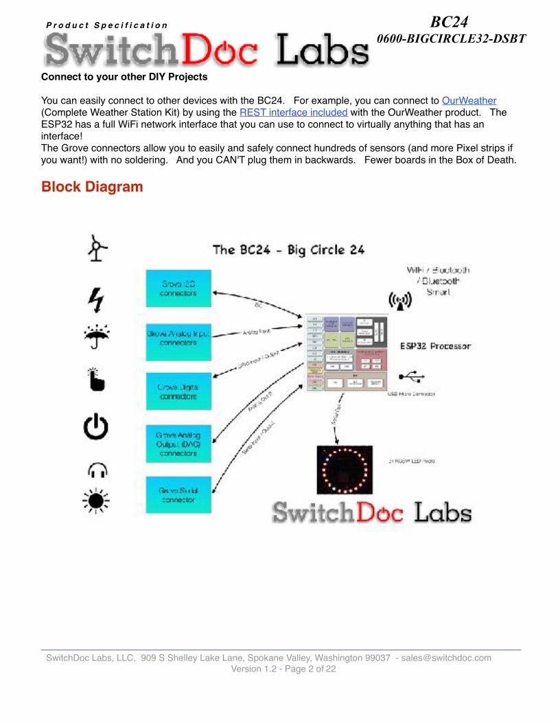
ESP32 w/WiFi and Bluetooth
Features of the ESP32 include the following:
Processors:• CPU: Xtensa dual-core (or single-core) 32-bit LX6 microprocessor, operating at 160 or 240 MHz and
performing at up to 600 DMIPS• Ultra low power (ULP) co-processor
Memory: • 520 KiB SRAM
Wireless connectivity:• Wi-Fi: 802.11 b/g/n• Bluetooth: v4.2 BR/EDR and BLE
Peripheral interfaces:• 12-bit SAR ADC up to 18 channels• 2 × 8-bit DACs• 10 × touch sensors (capacitive sensing GPIOs)
______________________________________________________________________________________ SwitchDoc Labs, LLC, 909 S Shelley Lake Lane, Spokane Valley, Washington 99037 - [email protected]
Version 1.2 - Page � of �4 22
BC24 0600-BIGCIRCLE32-DSBT
P r o d u c t S p e c i f i c a t i o n
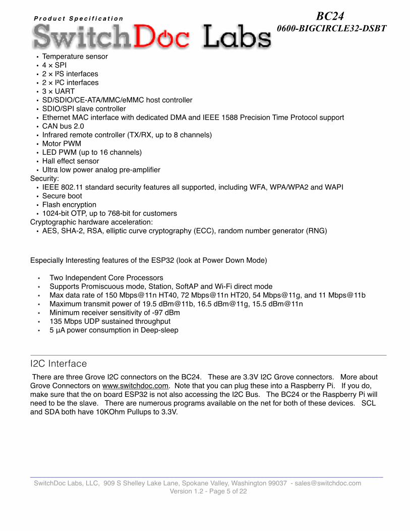
• Temperature sensor• 4 × SPI• 2 × I²S interfaces• 2 × I²C interfaces• 3 × UART• SD/SDIO/CE-ATA/MMC/eMMC host controller• SDIO/SPI slave controller• Ethernet MAC interface with dedicated DMA and IEEE 1588 Precision Time Protocol support• CAN bus 2.0• Infrared remote controller (TX/RX, up to 8 channels)• Motor PWM• LED PWM (up to 16 channels)• Hall effect sensor• Ultra low power analog pre-amplifier
Security:• IEEE 802.11 standard security features all supported, including WFA, WPA/WPA2 and WAPI• Secure boot• Flash encryption• 1024-bit OTP, up to 768-bit for customers
Cryptographic hardware acceleration: • AES, SHA-2, RSA, elliptic curve cryptography (ECC), random number generator (RNG)
Especially Interesting features of the ESP32 (look at Power Down Mode)
• Two Independent Core Processors• Supports Promiscuous mode, Station, SoftAP and Wi-Fi direct mode• Max data rate of 150 Mbps@11n HT40, 72 Mbps@11n HT20, 54 Mbps@11g, and 11 Mbps@11b• Maximum transmit power of 19.5 dBm@11b, 16.5 dBm@11g, 15.5 dBm@11n• Minimum receiver sensitivity of -97 dBm• 135 Mbps UDP sustained throughput• 5 μA power consumption in Deep-sleep
I2C Interface There are three Grove I2C connectors on the BC24. These are 3.3V I2C Grove connectors. More about Grove Connectors on www.switchdoc.com. Note that you can plug these into a Raspberry Pi. If you do, make sure that the on board ESP32 is not also accessing the I2C Bus. The BC24 or the Raspberry Pi will need to be the slave. There are numerous programs available on the net for both of these devices. SCL and SDA both have 10KOhm Pullups to 3.3V.
______________________________________________________________________________________ SwitchDoc Labs, LLC, 909 S Shelley Lake Lane, Spokane Valley, Washington 99037 - [email protected]
Version 1.2 - Page � of �5 22

BC24 0600-BIGCIRCLE32-DSBT
P r o d u c t S p e c i f i c a t i o n
The 24 RGBW Pixel String
The RGBW (Red Green Blue White) Pixels are completely programmable (millions of colors) and includes a bright white LED to give you pure warm white. These programmable pixels are 100% compatible with NeoPixels.RGWB Pixels are programmable four LED devices. They have Red, Green, Blue and a warm White LED. You can program each of the four LEDs from 0-255 resulting in millions of colors. The BC24 uses SK6812RGBW chips and they are programmed with a single serial GPIO line. These Pixels are 100% compatible with NeoPixels. This means you can put them together in very long strings. You can either add more strings to the BC24 or even extend the 24 LEDs included with more strips.
Driving the 24 Pixel RGBW String using RMT
The RMT (Remote Control) module driver in the ESP32 can be used to send and receive infrared remote control signals. Due to flexibility of RMT module, the driver can also be used to generate many other types of signals. The preferred method of driving Pixel RGBW strings with the BC24 is using the RMT device to keep from both loading the CPU as well as avoiding glitches in the string LEDs due to WiFi and other CPU interrupts.
See the BC24 Drivers on github.com/switchdoclabs
ERRATA
Version 0600-50418-01: Grove Connector J5 is mislabelled. J5 should be labeled D15/A5 (NOT D21/D4)
BC24 Notes on ConnectionsThe following signals are used on the BC24 for special purposes:
IO12_A1 - Connected to 1K Resistor in series with Red LED
IO17 - 10KOhm Pullup. Connected to SW1 - Mode Switch
IO21 - Connected to DIN of LED1 (First element in 24 Pixel String) through 300Ohm Resistor.
______________________________________________________________________________________ SwitchDoc Labs, LLC, 909 S Shelley Lake Lane, Spokane Valley, Washington 99037 - [email protected]
Version 1.2 - Page � of �6 22

BC24 0600-BIGCIRCLE32-DSBT
P r o d u c t S p e c i f i c a t i o n
Operating Values
BC24 Jumper Pin and Plug Locations
Physical dimensions of board: 89mm x 98mm x 10.5mm(max). Mounting holes inset 2.15mm x 2.15mm from each corner to center of hole. Diameter of hole 2mm.
I/O Key:
I - Digital Input O - Digital Output A - Analog
24 RGBW Pixel LED Display The Pixels are numbered on the board from LED1 to LED24. This corresponds to Pixel location 0 - 23.
These RGBW Pixels are NeoPixel compatible and are based on the SK6812RGBW 5050.
Min Normal Max Unit
5V 5.2 5.0 4.8 V
Input Current 200 ~450 mA
______________________________________________________________________________________ SwitchDoc Labs, LLC, 909 S Shelley Lake Lane, Spokane Valley, Washington 99037 - [email protected]
Version 1.2 - Page � of �7 22

BC24 0600-BIGCIRCLE32-DSBT
P r o d u c t S p e c i f i c a t i o n
Push Button Switch Functions
SW1 Mode Push Button
General Purpose User Button. Connected to a Pullup and to GPIO17.
SW2 RESET Push Button
Pushing this button resets the BC24 and restarts the sketch.
Arduino IDE
In order to install the Arduino IDE with support for the ESP32 on the BC24, please follow the excellent Adafruit tutorial here:
https://learn.adafruit.com/adafruit-huzzah32-esp32-feather/using-with-arduino-ide
______________________________________________________________________________________ SwitchDoc Labs, LLC, 909 S Shelley Lake Lane, Spokane Valley, Washington 99037 - [email protected]
Version 1.2 - Page � of �8 22

BC24 0600-BIGCIRCLE32-DSBT
P r o d u c t S p e c i f i c a t i o n
Jumper Plug Functions
______________________________________________________________________________________ SwitchDoc Labs, LLC, 909 S Shelley Lake Lane, Spokane Valley, Washington 99037 - [email protected]
Version 1.2 - Page � of �9 22
BC24 0600-BIGCIRCLE32-DSBT
P r o d u c t S p e c i f i c a t i o n
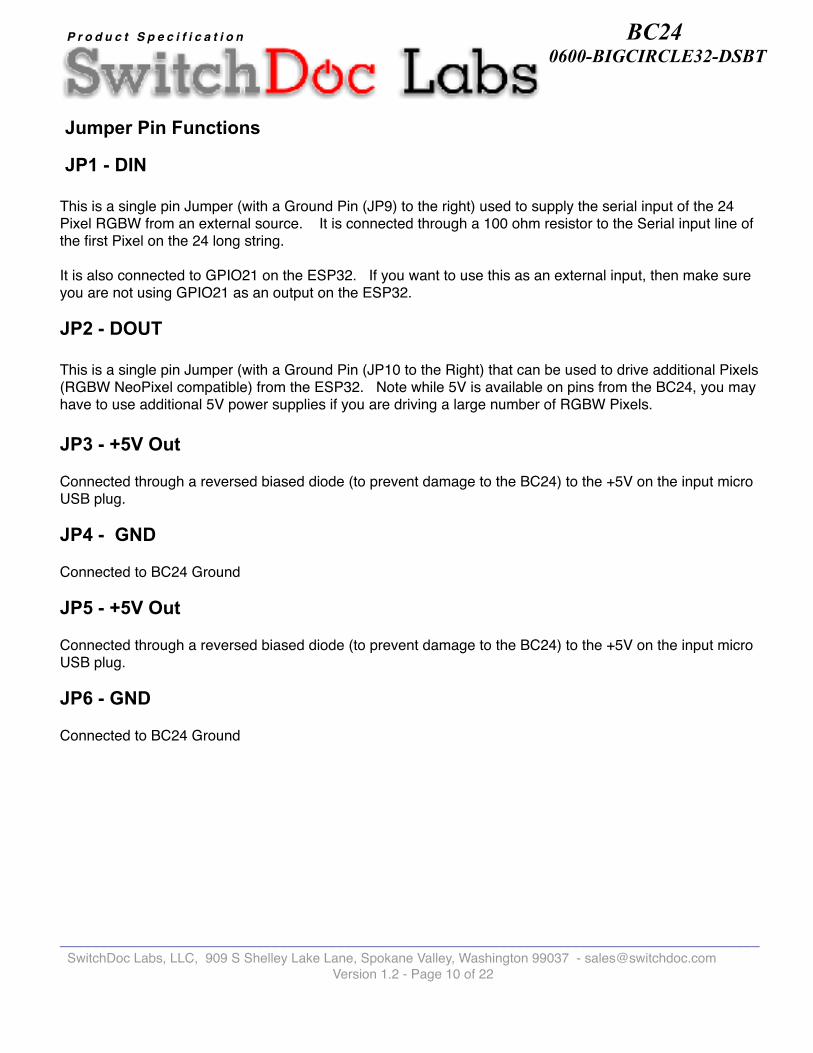
Jumper Pin Functions
JP1 - DIN
This is a single pin Jumper (with a Ground Pin (JP9) to the right) used to supply the serial input of the 24 Pixel RGBW from an external source. It is connected through a 100 ohm resistor to the Serial input line of the first Pixel on the 24 long string.
It is also connected to GPIO21 on the ESP32. If you want to use this as an external input, then make sure you are not using GPIO21 as an output on the ESP32.
JP2 - DOUT
This is a single pin Jumper (with a Ground Pin (JP10 to the Right) that can be used to drive additional Pixels (RGBW NeoPixel compatible) from the ESP32. Note while 5V is available on pins from the BC24, you may have to use additional 5V power supplies if you are driving a large number of RGBW Pixels. JP3 - +5V Out
Connected through a reversed biased diode (to prevent damage to the BC24) to the +5V on the input micro USB plug.
JP4 - GND
Connected to BC24 Ground
JP5 - +5V Out
Connected through a reversed biased diode (to prevent damage to the BC24) to the +5V on the input micro USB plug.
JP6 - GND
Connected to BC24 Ground
______________________________________________________________________________________ SwitchDoc Labs, LLC, 909 S Shelley Lake Lane, Spokane Valley, Washington 99037 - [email protected]
Version 1.2 - Page � of �10 22

BC24 0600-BIGCIRCLE32-DSBT
P r o d u c t S p e c i f i c a t i o n
JP7 - 16 Pin Feather Compatible Pin Header
Pin 1 is to the right on JP7.
NAME PIN I/O DESCRIPTION
SDA JP7/ 1 I/O I2C Serial Data Pin - 3.3V
SCL JP7/ 2 I/O I2C Serial Clock Pin - 3.3V
14 JP7/ 3 I/O GPIO #14 and also an analog input A6 on ADC #2
32 JP7/ 4 I/O GPIO #32 and also an analog input A7 on ADC #1. It can also be used to connect a 32 KHz crystal.
15 JP7/ 5 I/O GPIO #15 and also an analog input A8 on ADC #2
33 JP7/ 6 I/O GPIO #33 and also an analog input A9 on ADC #1. It can also be used to connect a 32 KHz crystal.
27 JP7/ 7 I/O GPIO #27 and also an analog input A10 on ADC #2
12 JP7/ 8 I/O GPIO #12 and also an analog input A11 on ADC #2. This pin has a pull-down resistor built into it, we recommend using it as an output only, or making sure that the pull-down is not affected during boot.
13 JP7/ 9 I/O GPIO #13 and also an analog input A12 on ADC #1. It's also connected to the red LED next to the ESP32 WiFi antenna
USB JP7/ 10 A +5V Power from micro USB Jack
EN JP7/ 11 I 3.3V regulator's enable pin. It's pulled up by a 100K resistor, so connect to ground to disable the 3.3V regulator
N/C JP7/ 12 A No Connection
______________________________________________________________________________________ SwitchDoc Labs, LLC, 909 S Shelley Lake Lane, Spokane Valley, Washington 99037 - [email protected]
Version 1.2 - Page � of �11 22

BC24 0600-BIGCIRCLE32-DSBT
P r o d u c t S p e c i f i c a t i o n
JP8 - 12 Pin Feather Compatible Pin Header
Pin 1 is to the right on JP8
JP9 - GND
Connected to BC24 Ground
NAME PIN I/O DESCRIPTION
21 JP8/ 1 I/O General purpose IO pin #21
TX JP8/ 2 O TX - Output FROM the module. 3.3V. These are additional Serial1 pins, and are not connected to the USB/Serial converter.
RX JP8/ 3 I RX - Input INTO the module. 3.3V. These are additional Serial1 pins, and are not connected to the USB/Serial converter.
MI JP8/ 4 I/O SPI
MO JP8/ 5 I/O SPI
SCK JP8/ 6 I/O SPI
A5 JP8/ 7 I/O analog input A5 and also GPIO #4. It uses ADC #2
A4 JP8/ 8 I analog input A4 and also GPI #36. Note it is not an output-capable pin! It uses ADC #1
A3 JP8/ 9 I analog input A3 and also GPI #39. Note it is not an output-capable pin! It uses ADC #1
A2 JP8/ 10 I analog input A2 and also GPI #34. Note it is not an output-capable pin! It uses ADC #1
A1 JP8/ 11 I/O analog input A1 and also an analog output DAC1. It can also be used as a GPIO #25. It uses ADC #2
A0 JP8/ 12 I/O this is an analog input A0 and also an analog output DAC2. It can also be used as a GPIO #26. It uses ADC #2
GND JP8/ 13 A BC24 Common Ground
N/C JP8/ 14
3V JP8/ 15 A output from the 3.3V regulator. The regulator can supply 500mA peak but most of that is drawn by the BC24.
RST JP8/ 16 I ESP32 Reset Pin. Connected to SW2 - Reset and to USB for Programming. Can pull to GND to reset.
______________________________________________________________________________________ SwitchDoc Labs, LLC, 909 S Shelley Lake Lane, Spokane Valley, Washington 99037 - [email protected]
Version 1.2 - Page � of �12 22

BC24 0600-BIGCIRCLE32-DSBT
P r o d u c t S p e c i f i c a t i o n
JP10 - GND
Connected to BC24 Ground
JP11 - Analog A13
General purpose input #35 and also an analog input A13. Not output capable
Micro USB ConnectorJP12 is a Micro USB Connector. It is used to program the ESP32 and to supply +5V power to the BC24.
Grove Connections
______________________________________________________________________________________ SwitchDoc Labs, LLC, 909 S Shelley Lake Lane, Spokane Valley, Washington 99037 - [email protected]
Version 1.2 - Page � of �13 22
BC24 0600-BIGCIRCLE32-DSBT
P r o d u c t S p e c i f i c a t i o n
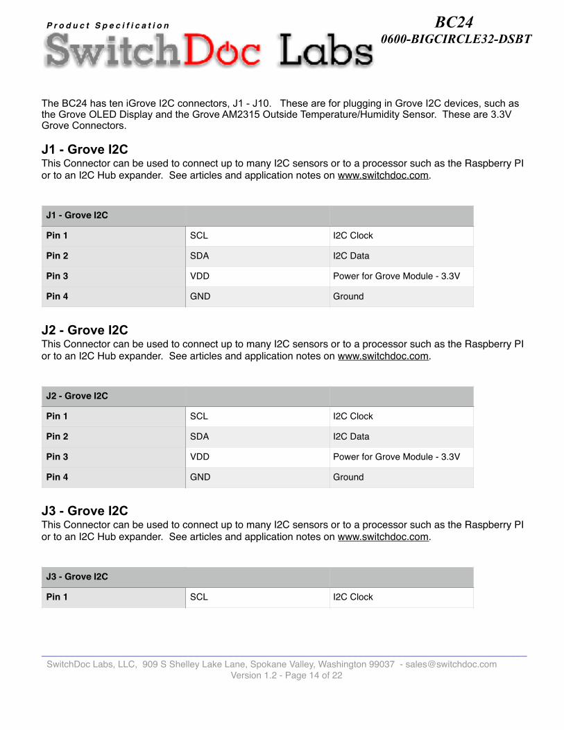
The BC24 has ten iGrove I2C connectors, J1 - J10. These are for plugging in Grove I2C devices, such as the Grove OLED Display and the Grove AM2315 Outside Temperature/Humidity Sensor. These are 3.3V Grove Connectors.
J1 - Grove I2C This Connector can be used to connect up to many I2C sensors or to a processor such as the Raspberry PI or to an I2C Hub expander. See articles and application notes on www.switchdoc.com.
J2 - Grove I2C This Connector can be used to connect up to many I2C sensors or to a processor such as the Raspberry PI or to an I2C Hub expander. See articles and application notes on www.switchdoc.com.
J3 - Grove I2C This Connector can be used to connect up to many I2C sensors or to a processor such as the Raspberry PI or to an I2C Hub expander. See articles and application notes on www.switchdoc.com.
J1 - Grove I2C
Pin 1 SCL I2C Clock
Pin 2 SDA I2C Data
Pin 3 VDD Power for Grove Module - 3.3V
Pin 4 GND Ground
J2 - Grove I2C
Pin 1 SCL I2C Clock
Pin 2 SDA I2C Data
Pin 3 VDD Power for Grove Module - 3.3V
Pin 4 GND Ground
J3 - Grove I2C
Pin 1 SCL I2C Clock
J3 - Grove I2C
______________________________________________________________________________________ SwitchDoc Labs, LLC, 909 S Shelley Lake Lane, Spokane Valley, Washington 99037 - [email protected]
Version 1.2 - Page � of �14 22

BC24 0600-BIGCIRCLE32-DSBT
P r o d u c t S p e c i f i c a t i o n
J4 - Grove Analog / Digital This connector can be used for both Analog Input and Digital Input/Output.
J5 - Grove Analog / Digital This connector can be used for both Analog Input and Digital Input/Output.
J6 - Grove Analog / Digital This connector can be used for both Analog Input and Digital Input/Output.
Pin 2 SDA I2C Data
Pin 3 VDD Power for Grove Module - 3.3V
Pin 4 GND Ground
J3 - Grove I2C
J4 - Grove Analog / Digital
Pin 1 IO14_A6 GPIO #14 and also an analog input A6 on ADC #2
Pin 2 IO15_A8 GPIO #15 and also an analog input A8 on ADC #2
Pin 3 VDD Power for Grove Module - 3.3V
Pin 4 GND Ground
J5 - Grove Analog / Digital
Pin 1 IO15_A8 GPIO #15 and also an analog input A8 on ADC #2
Pin 2 A5_IO4 analog input A5 and also GPIO #4. It uses ADC #2
Pin 3 VDD Power for Grove Module - 3.3V
Pin 4 GND Ground
______________________________________________________________________________________ SwitchDoc Labs, LLC, 909 S Shelley Lake Lane, Spokane Valley, Washington 99037 - [email protected]
Version 1.2 - Page � of �15 22

BC24 0600-BIGCIRCLE32-DSBT
P r o d u c t S p e c i f i c a t i o n
J7 - Grove Analog / Digital This connector can be used for both Analog Input and Digital Input/Output.
J8 - Grove Analog / Analog Output / Digital This connector can be used for both Analog Input, Analog Output and Digital Input/Output.
J6 - Grove Analog / Digital
Pin 1 IO32_A7 GPIO #32 and also an analog input A7 on ADC #1. It can also be used to connect a 32 KHz crystal.
Pin 2 IO33_A9 GPIO #33 and also an analog input A9 on ADC #1. It can also be used to connect a 32 KHz crystal.
Pin 3 VDD Power for Grove Module - 3.3V
Pin 4 GND Ground
J7 - Grove Analog / Digital
Pin 1 IO27_A10 GPIO #27 and also an analog input A10 on ADC #2
Pin 2 A3_I39 analog input A3 and also GPI #39. Note it is not an output-capable pin! It uses ADC #1
Pin 3 VDD Power for Grove Module - 3.3V
Pin 4 GND Ground
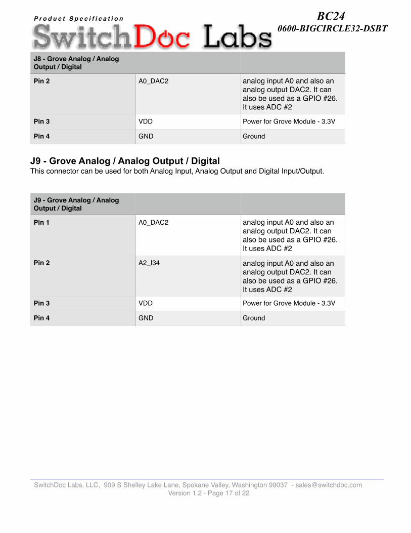
J8 - Grove Analog / Analog Output / Digital
Pin 1 A1_DAC1 analog input A1 and also an analog output DAC1. It can also be used as a GPIO #25. It uses ADC #2
J8 - Grove Analog / Analog Output / Digital
______________________________________________________________________________________ SwitchDoc Labs, LLC, 909 S Shelley Lake Lane, Spokane Valley, Washington 99037 - [email protected]
Version 1.2 - Page � of �16 22
BC24 0600-BIGCIRCLE32-DSBT
P r o d u c t S p e c i f i c a t i o n
J9 - Grove Analog / Analog Output / Digital This connector can be used for both Analog Input, Analog Output and Digital Input/Output.
Pin 2 A0_DAC2 analog input A0 and also an analog output DAC2. It can also be used as a GPIO #26. It uses ADC #2
Pin 3 VDD Power for Grove Module - 3.3V
Pin 4 GND Ground
J8 - Grove Analog / Analog Output / Digital
J9 - Grove Analog / Analog Output / Digital
Pin 1 A0_DAC2 analog input A0 and also an analog output DAC2. It can also be used as a GPIO #26. It uses ADC #2
Pin 2 A2_I34 analog input A0 and also an analog output DAC2. It can also be used as a GPIO #26. It uses ADC #2
Pin 3 VDD Power for Grove Module - 3.3V
Pin 4 GND Ground
______________________________________________________________________________________ SwitchDoc Labs, LLC, 909 S Shelley Lake Lane, Spokane Valley, Washington 99037 - [email protected]
Version 1.2 - Page � of �17 22
BC24 0600-BIGCIRCLE32-DSBT
P r o d u c t S p e c i f i c a t i o n
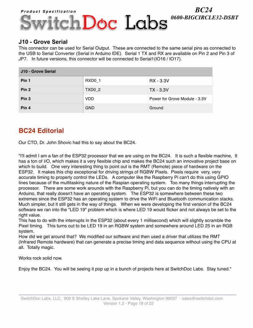
J10 - Grove Serial This connector can be used for Serial Output. These are connected to the same serial pins as connected to the USB to Serial Converter (Serial in Arduino IDE). Serial 1 TX and RX are available on Pin 2 and Pin 3 of JP7. In future versions, this connector will be connected to Serial1(IO16 / IO17).
BC24 EditorialOur CTO, Dr. John Shovic had this to say about the BC24.
"I'll admit I am a fan of the ESP32 processor that we are using on the BC24. It is such a flexible machine, It has a ton of I/O, which makes it a very flexible chip and makes the BC24 such an innovative project base on which to build. One very interesting thing to point out is the RMT (Remote) piece of hardware on the ESP32. It makes this chip exceptional for driving strings of RGBW Pixels. Pixels require very, very accurate timing to properly control the LEDs. A computer like the Raspberry Pi can't do this using GPIO lines because of the multitasking nature of the Raspian operating system. Too many things interrupting the processor. There are some work arounds with the Raspberry Pi, but you can do the timing natively with an Arduino, that really doesn't have an operating system. The ESP32 is somewhere between these two extremes since the ESP32 has an operating system to drive the WiFi and Bluetooth communication stacks. Much simpler, but it still gets in the way of things. When we were developing the first version of the BC24 software we ran into the "LED 19" problem which is where LED 19 would flicker and not always be set to the right value. This has to do with the interrupts in the ESP32 (about every 1 millisecond) which will slightly scramble the Pixel timing. This turns out to be LED 19 in an RGBW system and somewhere around LED 25 in an RGB system.How did we get around that? We modified our software and then used a driver that utilizes the RMT (Infrared Remote hardware) that can generate a precise timing and data sequence without using the CPU at all. Totally magic.
Works rock solid now.
Enjoy the BC24. You will be seeing it pop up in a bunch of projects here at SwitchDoc Labs. Stay tuned."
J10 - Grove Serial
Pin 1 RXD0_1 RX - 3.3V
Pin 2 TXD0_2 TX - 3.3V
Pin 3 VDD Power for Grove Module - 3.3V
Pin 4 GND Ground
______________________________________________________________________________________ SwitchDoc Labs, LLC, 909 S Shelley Lake Lane, Spokane Valley, Washington 99037 - [email protected]
Version 1.2 - Page � of �18 22

BC24 0600-BIGCIRCLE32-DSBT
P r o d u c t S p e c i f i c a t i o n
Software See the BC24 Product Page on shop.switchdoc.com for a complete list of available software and drivers.
Sample Projects
Build a Air Quality Detector Turning the BC24 into a Indoor Air Quality Sensor is simple. We use an Analog Grove Air Quality Sensor and plug it in. Then a bit of software magic and you have a new device! This is an amazingly sensitive sensor. See our article here on this sensor.
Build a Solar Powered Display
______________________________________________________________________________________ SwitchDoc Labs, LLC, 909 S Shelley Lake Lane, Spokane Valley, Washington 99037 - [email protected]
Version 1.2 - Page � of �19 22

BC24 0600-BIGCIRCLE32-DSBT
P r o d u c t S p e c i f i c a t i o n
You can easily convert the BC24 into a solar powered system by using the SwitchDoc Labs SunControl Solar Power Controller and Data Gathering board along with a LiPo battery and solar panels. Just plug them together using Grove cables. How is that for a fancy night light in your yard!
______________________________________________________________________________________ SwitchDoc Labs, LLC, 909 S Shelley Lake Lane, Spokane Valley, Washington 99037 - [email protected]
Version 1.2 - Page � of �20 22

BC24 0600-BIGCIRCLE32-DSBT
P r o d u c t S p e c i f i c a t i o n
Build a Weather Station With the powerful ESP32 processor on the BC24, you can easily build a full weather station using the BC24. See our Reward for just that. Includes Anemometer, Wind Vane, Rain Bucket, Indoor temperature and humidity, outdoor temperature and humidity and a sunlight and UV sensor.
Connect The BC24 to Amazon Alexa
SwitchDoc Labs has connected a variety of their products to the Amazon Alexa system. You can learn how to connect the Raspberry Pi to Alexa here.
______________________________________________________________________________________ SwitchDoc Labs, LLC, 909 S Shelley Lake Lane, Spokane Valley, Washington 99037 - [email protected]
Version 1.2 - Page � of �21 22

BC24 0600-BIGCIRCLE32-DSBT
P r o d u c t S p e c i f i c a t i o n
SwitchDoc is building the software for the BC24 to connect it up to Alexa. For what? We don't know yet. But we will have fun figuring it out.
Connect to your other DIY Projects
You can easily connect to other devices with the BC24. For example, you can connect to OurWeather (Complete Weather Station Kit) by using the REST interface included with the OurWeather product. The ESP32 has a full WiFi network interface that you can use to connect to virtually anything that has an interface!
______________________________________________________________________________________ SwitchDoc Labs, LLC, 909 S Shelley Lake Lane, Spokane Valley, Washington 99037 - [email protected]
Version 1.2 - Page � of �22 22