![Operation of Offshore Wind Farms Connected with DRU-HVDC ... · frequency control of an offshore network by WTs connected to a DRU-HVDC system was proposed in [3], which proves that](https://static.fdocuments.in/doc/165x107/5f05593f7e708231d41285c4/operation-of-offshore-wind-farms-connected-with-dru-hvdc-frequency-control-of.jpg)
Evolution of the HVDC Link Connecting Offshore Wind Farms ...
17
energies Article Evolution of the HVDC Link Connecting Offshore Wind Farms to Onshore Power Systems Roland Ryndzionek * and Lukasz Sienkiewicz Faculty of Electrical and Control Engineering, Gda ´ nsk University of Technology, 80-233 Gda´ nsk, Poland; [email protected] * Correspondence: [email protected] Received: 22 January 2020; Accepted: 4 April 2020; Published: 14 April 2020 Abstract: This paper presents an overview of the DC link development and evolution dedicated to HVDC structure for connecting offshore wind power plants to onshore power systems. The growing demand for the green energy has forced investors in power industry to look for resources further out at sea. Hence, the development of power electronics and industrial engineering has enabled offshore wind farms to be situated further from the shore and in deeper waters. However, their development will require, among other technologies, DC-DC conversion systems. The advantages of HVDC over HVAC technology in relation to transmission distance are given. The different HVDC configurations and topologies of HVDC converters are elucidated. In this context, the HVDC grids are a promising alternative for the expansion of the existing AC grid. Keywords: HVDC transmission; HVDC; offshore wind energy; DCDC converter; voltage source converter; multi-terminal HVDC 1. Introduction The growing demand for the green energy has forced investors in power industry to look for resources further out at sea. Hence, the development of power electronics and industrial engineering has enabled offshore wind farms to be situated further from the shore and in deeper waters [1]. Each investment must be assessed in terms of resource evaluation, grid connection and operation, which applies to deep offshore projects, in particular [2,3]. To improve the cost-effectiveness of offshore designs, it will be essential to implement a technology optimizing architecture at a system level [4,5]. Today, wind energy has become the largest form of power generation capacity in Europe with coal been the second. In 2015, the European Union had 142 GW of installed wind power capacity: including 131 GW installed on the shore and 11 GW installed offshore. In 2016, there were 153.7 GW of installed wind power capacity including 141.1 GW installed on the shore and 12.6 GW installed offshore. The total net installed power generation capacity in EU achieved 919 GW in 2016 [6]. In 2017, a record of 3.15 MW net additional installed capacity in offshore wind energy was reached. This was equivalent to 560 new offshore wind turbines across 17 wind power plants [7]. In 2018, Europe connected 409 new offshore wind turbines to the grid covering 18 projects with an additional capacity of 2.649 MW (At the moment there is no official information about 2019) [8]. Moreover, in European Union renewable electricity generation by source (non-combustible) shows a huge increase of wind power. According to the IEA data analysis [9], this is over 100 % since 2010—150 TWh in 2010 versus 360 TWh in 2017. Comparing to the hydro-based energy source, which is constant and is about 300 TWh, wind energy has overtaken all renewable sources [10]. The offshore wind power market is a few times smaller than the onshore market is, so it enables a huge opportunity for investment and future development. To meet requirements, efficiency, security Energies 2020, 13, 1914; doi:10.3390/en13081914 www.mdpi.com/journal/energies
Transcript of Evolution of the HVDC Link Connecting Offshore Wind Farms ...

energies
Article
Evolution of the HVDC Link Connecting OffshoreWind Farms to Onshore Power Systems
Roland Ryndzionek * and Łukasz Sienkiewicz
Faculty of Electrical and Control Engineering, Gdansk University of Technology, 80-233 Gdansk, Poland;[email protected]* Correspondence: [email protected]
Received: 22 January 2020; Accepted: 4 April 2020; Published: 14 April 2020
Abstract: This paper presents an overview of the DC link development and evolution dedicated toHVDC structure for connecting offshore wind power plants to onshore power systems. The growingdemand for the green energy has forced investors in power industry to look for resources further outat sea. Hence, the development of power electronics and industrial engineering has enabled offshorewind farms to be situated further from the shore and in deeper waters. However, their developmentwill require, among other technologies, DC-DC conversion systems. The advantages of HVDC overHVAC technology in relation to transmission distance are given. The different HVDC configurationsand topologies of HVDC converters are elucidated. In this context, the HVDC grids are a promisingalternative for the expansion of the existing AC grid.
Keywords: HVDC transmission; HVDC; offshore wind energy; DCDC converter; voltage sourceconverter; multi-terminal HVDC
1. Introduction
The growing demand for the green energy has forced investors in power industry to look forresources further out at sea. Hence, the development of power electronics and industrial engineeringhas enabled offshore wind farms to be situated further from the shore and in deeper waters [1].Each investment must be assessed in terms of resource evaluation, grid connection and operation,which applies to deep offshore projects, in particular [2,3]. To improve the cost-effectiveness of offshoredesigns, it will be essential to implement a technology optimizing architecture at a system level [4,5].
Today, wind energy has become the largest form of power generation capacity in Europe withcoal been the second. In 2015, the European Union had 142 GW of installed wind power capacity:including 131 GW installed on the shore and 11 GW installed offshore. In 2016, there were 153.7 GW ofinstalled wind power capacity including 141.1 GW installed on the shore and 12.6 GW installed offshore.The total net installed power generation capacity in EU achieved 919 GW in 2016 [6]. In 2017, a recordof 3.15 MW net additional installed capacity in offshore wind energy was reached. This was equivalentto 560 new offshore wind turbines across 17 wind power plants [7]. In 2018, Europe connected 409new offshore wind turbines to the grid covering 18 projects with an additional capacity of 2.649 MW(At the moment there is no official information about 2019) [8].
Moreover, in European Union renewable electricity generation by source (non-combustible)shows a huge increase of wind power. According to the IEA data analysis [9], this is over 100 %since 2010—150 TWh in 2010 versus 360 TWh in 2017. Comparing to the hydro-based energy source,which is constant and is about 300 TWh, wind energy has overtaken all renewable sources [10].
The offshore wind power market is a few times smaller than the onshore market is, so it enables ahuge opportunity for investment and future development. To meet requirements, efficiency, security
Energies 2020, 13, 1914; doi:10.3390/en13081914 www.mdpi.com/journal/energies

Energies 2020, 13, 1914 2 of 17
and market access, wind power plants are moved further and further into the open sea because thegrid becomes more demanding.
The main challenge in the development of large offshore wind power projects lies in transmittingpower generated by an offshore plant to the onshore electricity grids as efficiently as possible. To reachthe full potential of offshore wind power plant (OWPP), new electric connections with improvedreliability and efficiency to the onshore grids are required [6].
1.1. Development of Horizontal Wind Power Plants
In wind farms with capacities above 100 kW, mainly horizontal axis wind turbine (HAWT)are used. As a result, a high level of maturity and standardization of technical solutions for thistype of construction have been achieved. Scaling the power of the HAWT power plant is relativelysimple—increasing the power is achieved by increasing the rotor diameter. With the advances inaerodynamics, materials science and power electronics, it became possible to build a power plant withunit powers of up to 10 MW (Figure 1a,b).
An important stage in the development of wind farm manufacture is at the turn of the 1970s and1980s and is associated with the search for alternative energy sources due to the fuel crisis. Innovativeconstructions were designed as part of two projects financed by the US government: high windsproject coordinated by NASA and small wind project coordinated by Sandia National Lab. As partof the project implemented by NASA, HAWT turbine designs with outputs from 100 kW to 4.2 MWwere developed.
0
25
50
75
100
125
150
175
1975 1980 1985 1990 1995 2000 2005 2010 2015 2020 2025 2030
Hu
be
hei
gh
t [m
]
Installation date
2 MW
1.25 MW
0.1 MW
2 MW
1.25 MW
0.1 MW 2 MW 2.5 MW
4.2 MW
(a)
0
25
50
75
100
125
150
175
0 2 4 6 8 10 12 14
Hu
be
hig
ht
[m]
Power [MW]
H=40 m, D=30 m
H=62.5 m, D=53m
H=80 m, D=54 m
H=73.17 m, D=61m
H=62.5 m, D=53 m
H=40 m, D=30 m
H=80 m, D=54 m
H=73.17 m, D=61 m
H=119.6 m, D=79.2 m
H=106.66 m, D=91.4 m
(b)
Figure 1. (a) Development of wind power plants with HAWT turbines—date of installation of thelargest power plants. Where red color USA, blue color EU. (b) Development of wind turbines withHAWT type turbines—dependence of turbine size (height and diameter) on wind power output. Wherered color USA, blue color EU.
In the 21st century, the leaders in the field of wind farms with HAWT were European companies(REpower, Vestas, Enercon, Siemens) (Figure 1a). Synchronous generators (either singular or multiple)are the primary input of electrical energy [11]. Wind farms have started to be located offshore, whereat a lower height of towers better wind conditions can be obtained. Currently, the wind plant capacityincrease is achieved by increasing the active surface of the turbine (blade lengths up to 107 m).

Energies 2020, 13, 1914 3 of 17
1.2. DC Grids Requirements
The HVDC requirements have been determined based on [12]. The main data are presented inthe Table 1.
Table 1. Requirements for low, medium and high power HVDC grids.
Parameter Classification Range
Low Pdc < 50 MWTransferred DC Power Medium 50 MW < Pdc < 500 MW
High 500 MW < Pdc
Low 1 < Ratio < 1.5Transformation Ratio Medium 1.5 < Ratio < 5Vdc-high/Vdc-low High 5 < Ratio
HV side DC Voltage Medium Vdc < 100 kVHigh 100 kV < Vdc
Offshore wind power market has a complex supply chain, thus millions of EUR investments init create thousands of new jobs. Based on the European Wind Energy Association, there are around75,000 jobs directly related to offshore wind power in Europe [13,14]. The growth of this sector createsalso opportunities to develop and attract the investors to remote cities in Northern Germany, Denmarkand the United Kingdom, e.g., ports of Cuxhaven and Bremerhaven, Mostyn and Grimsby in theUnited Kingdom where the wind power becomes the main sector of the local economy. The number ofprojects under development demonstrates great potential for further growth of this sector [14,15].
In this work the authors give an outline of HVDC transmission systems bridging offshore windpower plants with onshore power system. This review takes into account different existing andresearched technologies of converters used in HVDC. The advantages of HVDC over HVAC technologyin relation to transmission distance are given in Section 2, where also a new break-even-distance foroffshore installations is demonstrated. The different HVDC configurations and topologies of HVDCconverters are explained in Section 3. Finally, possible development paths and future solutions forintegration of OWPPs are suggested in Section 4.
2. HVAC vs. HVDC
The HVDC transmission has been used for many years thus the technology is mature. Particularlyover long distances, it has great advantages over HVAC. The advantage of DC-DC converter topologiesamid existing AC solutions for longer distance transmission has been established in literature [16,17].The most desirable advantages of HVDC transmission line in contrast to AC line cover: absence of theskin effect; reduced transmission losses particularly for long, high voltage applications due to lack ofreactive charging currents; cheaper and less demanding manufacture process of DC cables, especiallyfor long and ultra-high voltage DC cables and higher degree of active power control.
The main drawback of HVDC vs. HVAC transmission, which is the high cost of power electronicterminals, is still valid. Nonetheless, the gradual adoption of cheaper and more efficient transistormodules (e.g., SiC) in recent years may shift the balance in favour of DC transmission [18,19].
Before large-scale offshore wind farms were built, HVDC offshore transmission lines wereconstructed. In general, more than 60 DC stations, and 52 of which are HVDC, have been builtsince 1960 in Europe (including a project which will be launched in 2020). It is worth emphasizing thefact that in the last 5 years as many as 26 stations have been launched [20]. Which represents 40 % ofthe stations built.

Energies 2020, 13, 1914 4 of 17
It is clear that some stations have been closed and some have been modernized and upgraded.Nevertheless, the number of recent projects gives a picture of how fast the DC industry is growing.Chosen DC-DC interconnections have been presented in Table 2.
Table 2. A selection of HVDC transmission lines in Europe [20]
Name Link Total km Voltage (kV) Power (MW) Year
Baltic Cable Germany–Sweden 262 450 600 1994SwePol Poland–Sweden 245 450 600 2000
Italy-Greece Italy–Greece 310 400 500 2001NorNed Netherlands–Norway 580 450 700 2008BritNed UK–Netherlands 245 450 1000 2010
NordBalt Sweden–Lithuania 450 300 700 2015DolWin2 Germany–Germany 135 320 900 2016
Western HVDC Link UK–UK 422 600 2200 2017ElecLink France–UK 70 320 1000 2019
Caithness Moray HVDC France–UK 70 320 1000 2019NORD.LINK Norway–Germany 623 525 1400 2020
NSN Link Norway–England 730 515 1400 2020
The general approach which can be observed for a few years in the power industry is to developan integrated system to fully utilize the potential of the wind farm and provide savings in space [16,21].HVAC has the advantage to operate with relatively inexpensive terminals whereas HVDC needs toapply quite costly power converter stations. Moreover, for long distances (like in the case of remoteoffshore locations), the extra cost of power converters is counterbalanced by cost savings on cheaperDC cables and smaller transmission losses [22]. Additionally, HVDC cables (especially utilizingcross-linked polyethylene as an insulation) have less weight than regular cables. Thus, it is possible totransport longer sections of cable, due to the lower ratio between weight and unit length [23]. The DCtransmission systems offer a more cost-effective choice than AC transmission systems when remote,high power delivery is concerned. Such critical distance is called a break-even-distance (Figure 2).In such context, the development of an offshore grid would be particularly beneficial.
Figure 2. AC vs. DC break-even-distance for a large power wind farms [24–26].

Energies 2020, 13, 1914 5 of 17
The use of direct current for higher power wind plants to suggest a lower price point is verychallenging (DC-DC converter cost being a crucial factor) (Figure 2). The distance depends on severalfactors (both for lines and cables) and analysis must be made for each individual case [27]. For HVDConshore transmission line the break-even-distance is approx. 600–800 km [24,25]. However, thebreak-even-distance is much smaller for sub sea cables (typically about 50 km) than for an overheadline transmission [28]. In general, new OWPP are built more than 100 km from shore [26].
3. HVDC Offshore Technologies Comparison
The HVDC transmission systems are among the basic elements of future-oriented intelligentpower grids referred to as Smart Grid. The development of such a network is aimed at increasingsystem security and energy efficiency through the use of modern equipment and the integrationof renewable sources. In general, HVDC systems are implemented by means of a transmissionsystem consisting of converter stations and a DC cable line. Currently, there are a number of layoutconfigurations available, which can basically fall into two groups: Back-to-Back layouts (BtB) andsystems for long-distance power transmission.
The “oldest” and most popular are solutions based on thyristor, called Line CommutatedConverters (LCC), also known as “classical HVDC”. Newer systems are based on transistors and arecalled Voltage source converters (VSC) [29]. Both systems require an expensive HVAC transformer’platforms (represented by blue color in the following figures) and HVDC platforms (represented byblue orange in the following figures), AC and DC filters, converter valves and the control system.The typical HVDC scenario used for linking of OWPP with onshore power system is shown in Figure 3.
Wind turbine transformers step up the voltage from 690 V typically to 25–40 kV, as higher voltagetransformers would be too large to fit into the tower cross-section. The typical power rating of theturbine side converter is 5–10 MW. Collection systems mostly utilize the 33–36 kV AC to gather theenergy from the wind farm [5,30]. High voltage submarine cables connect the wind turbine output tothe offshore platform. High voltage transformer at the offshore platform steps up the collection systemvoltage to the level of 132–150 kV (in some OWPP even 400 kV) for transmission and interconnectionto the onshore grid by DC line, which is typically 320 kV [28,31,32].
Figure 3. Common scenario for connecting offshore wind power to main ac network utilizingHVDC technology.
The largest players in the HVDC industry who invest in network development are: ABB, Siemensand Alstom Grid (since 2017 GE Grid). Chosen HVDC offshore wind power plants in Europe havebeen presented in Table 3.

Energies 2020, 13, 1914 6 of 17
Table 3. A selection of HVDC offshore wind power plants in Europe [20]
Name Power [MW] AC / DC Voltage [kV] DC Submarine/Underground Cable [km] Year
BorWin1 400 170/150 2 × 75/2 × 125 2009SylWin1 864 -/320 2 × 159/2 × 45 2014DolWin2 916 155/320 2 × 45/2 × 90 2015BorWin2 800 380/300 2 × 125/2 × 75 2015HelWin2 690 -/320 2 × 45/2 × 85 2015
Nordsee Ost 422 155/250 2 × 57/2 × 20 2015DolWin3 690 170/320 2 × 45/2 × 85 2017BorWin3 900 380/320 2 × 130/2 × 30 2019
3.1. Line Commutated Converters
LCC converters technology is well known and mature (Figure 4). The advantage of LCC convertersis their large operating experience and relatively low price. Thyristor based converters are characterizedby high voltage even 600 kV and high power ratings. The thyristor technology required a strong ACgrid and active power control.
Figure 4. Detailed view of offshore wind power transmission schematics based on LCC HVDCtechnology (where RSC—rotor side converter GSC—grid side converter, PMSG—permanent magnetsynchronous generator).
Broad use of transistors revolutionized the HVDC technology, which in turn rendered the LCC asless viable for offshore applications.
3.2. Voltage Source Converters
The development of power semiconductors, including fully controllable devices such as GTOsand IGBT transistors, has driven the use of the voltage source converter (VSC) in HVDC systems.The two-level converter has been developed in 1997 [33]. Since 1999, the voltage source converter withIGBT transistors has been widely used as a HVDC terminal. This solution has been applied in the firstHVDC commercial project with offshore wind power plant [34,35].
The VSC technology in HVDC systems (Figure 5) has many advantages like compactness,black-start capability, the capability to connect to weak AC networks, independent control of activeand reactive power [36–40]. Consequently, it has become the preferred HVDC converter technologyfor connecting OWPP e.g Borwin1 by ABB (2009, 400 MW, 125 offshore + 75 onshore km), Sylwin1by Siemens (2014, 864 MW, 159 offshore + 45.5 onshore km) and DolWin3 by Alstom (2017, 900 MW,84.5 offshore + 76.5 onshore km).

Energies 2020, 13, 1914 7 of 17
Figure 5. Detailed view of offshore wind power transmission schematics with VSC-based HVDCtechnology—Point-to-point connection(where RSC—rotor side converter GSC—grid side converter,PMSG—permanent magnet synchronous generator).
Over time, the VSC technology has been evolving. The three-level PWM controlled convertershave been developed. Moreover, the converters become more efficient due to the development oftransistor technology (Si IGBT power modules). After that, many attempts were made to invent threeor multi-levels topology and apply it in HVDC [29] e.g., neutral point clamped converters (NPC) andits variety - 3L-ANPC, 5L-HNPC, CHB or diode-clamped converter (DCC). However, only NPC wereadopted broadly by the industry (Figure 6a). The developments of the three-level converters resultedin reduced harmonic generation, reduction of losses to approximately 1.7% and full control of offshoregrid’s dynamics.
Figure 6. VSC HVDC technology (a) the NPC three level converter, (b) MMC—ModularMultilevel Converter.
An example of a modern multilevel structure is a Modular Multilevel Converter (MMC)(Figure 6b). This topology was developed in the early 2000s and received increased attention sincethen [32,41]. MMC converters are the preferred technology in today’s VSC-HVDC. The MMC is a typeof cascaded multilevel converter which is based on series connection of sub-modules (SMs). Single SMis composed of a half-bridge converters connected in series.
The advantage of the MMC is possibility to generate a staircase voltage waveform. The shape ofthis voltage depends on number of SMs used in specific topology—more SMs give a more sinusoidalwaveform [42,43]. However, to simplify the deployment of OWPP, new strategies to reach higherefficiency and better reliability of the converters are necessary to be developed. Moreover, using ahigher voltage will reduce transmission losses [44].

Energies 2020, 13, 1914 8 of 17
3.3. HVDC Diode Rectifier Unit
In last few years the new type of solution based on diode rectifier unit (DRU) has been underinvestigation. This concept was called “2nd generation DC grid access for offshore wind farms” bySiemens [45,46]. The main idea is to replace the AC by an AC-DC offshore substations, directly linkedwith the turbines (Figure 7).
Figure 7. The HVDC transmission topology based on the diode rectifier (where RSC—rotor sideconverter GSC—grid side converter, PMSG—permanent magnet synchronous generator).
First and foremost, HVDC diode rectifier offers reduced costs and increased reliability due tothe lack of offshore DC converter as a unique malfunction location. Moreover, using distributedsmall DC platforms it is possible to achieve high reliability, low maintenance efforts and mostimportant—small platforms with easy transport and installation. A diode is the simplest and themost robust semiconductor in power electronics. Using diodes instead of transistors (as in VSC)leads to lowering the number of auxiliary components such as: dc breakers, discharge resistors, gatedrivers [47]. Going further, the simplest solutions are desired and that could be realized by a dioderectifier. The main premise of DRU is the simplicity of distributed DC platforms without sacrificingthe robustness [48,49].
In literature, 6-pulse or 12-pulse diode rectifiers are commonly described (with 18 and 24 pulsepresent as well [46,50–53]). The first is built as a 6 pulse diode bridge consisting of six uncontrollablediodes and a low-pass filter for smoothing the DC current [54]. The second is formed by dual 6-pulsediode bridges joined in series and feeding a common DC bus, together with a special three-windingtransformer (with secondary voltages in 30 degrees phase shift) at the supply side of the rectifier.The HVDC link will comprise three 200 MW diode rectifier converters with their outputs constitutinga 640 kV pole-to-pole DC link to be connected to the onshore DC/AC power conversion station(Figure 8).
The diode rectifier is combining the active module of a transformer with a 12-pulse DRU andadditional equipment which simplifies the topology and reduces the quantity of electric components,particularly on high voltage side. Moreover, in contrast to thyristors, diodes do not need guardingagainst the high current deltas at start-up, are less sensitive to failure within the recovery period nordo they require extra effort for installing and diagnostics [55,56].
However, this solution has some drawbacks which have to be investigated. The main issue is thatthe DRU is a non-controllable device. In this case, the OWPP AC system has to be controlled by thewind turbine. Moreover, various wind turbines and OWPP topologies are required. A DRU is not ableto provide reactive power, needing power converters or other devices to compensate it [46]. In largescale, a DRU concept may be a key factor in determining, if offshore wind farms are commerciallyviable [27,45,57,58].

Energies 2020, 13, 1914 9 of 17
Figure 8. The schematics of (a) 6-pulse and (b) 12-pulse diode rectifier HVDC links.
3.4. Hybrid LCC/VSC Schemes
The hybrid topology (Figure 9) is developed in parallel to VSC technology and is defined as a mixof topologies described in previous chapters. The main benefits that come from such approach arelower losses compared to pure VSC (due to the LCC switching mechanism) or fact that many VSCscan be connected to a single LCC which may represent a more economic and robust investment (lessswitching devices). The hybrid topology has disadvantages such as managing of a DC link’s dischargefor reversed power flow [59–61]. Moreover, some aspects of the hybrid technology are technicallychallenging: higher insulation requirement on the wind turbines, selected electrical equipment of theWPP must be oversized to prevent over-voltages from occurring in the turbines [62].
Figure 9. General overview of the HVDC hybrid transmission system based on VSC and LCCtechnology [60].
In literature a various configurations are developed. The interesting solution is reported in [63,64]which described a hybrid topology of the 12-pulse diode rectifiers and a VSC (Figure 10). The 12-pulsediode rectifier is able to deliver a large amount of the OWPP output power, which is decreasing thenecessary power rating of the VSC.
Figure 10. General overview of the HVDC hybrid transmission system [63].

Energies 2020, 13, 1914 10 of 17
The VSC generates the onshore AC voltage at the constant magnitude and constant frequency.In addition, the VSC is able to compensate for the 11th and 13th order current harmonics due to the12-pulse diode rectifier (an active power filter operation). The calculated efficiency is 99.07 % and costof power devices is 53.47 % of VSC HVDC system [65]. Finally, this system will fit in the same size asVSC HVDC stations.
3.5. Costs Comparison
In Figure 5 Point-to-point connection has been presented. This kind of a connection is the moststraightforward HVDC offshore wind farm configuration. However, the new concepts and topologies,described in the preceding paragraphs, are being developed. In [66] a detailed cost analysis fordifferent DC offshore collections grids has been performed. In Figures 11 and 12 cost and differentconfigurations of modern DC-DC offshore wind farm have been presented. The viability analysis dealswith the assessment of the total cost of a OWPP with the complete transmission system. These resultspresent a starting point for the comparison between AC and DC OWPP plan profiles and enable adecision which one is the most cost-effective.
Figure 11. The proposed DC OWPP configurations: (a) DC1, (b) DC2, (c) DC3, (d) DC4.
The DC1 is a configuration where there is a straight connection between turbine feeders andthe HVDC main substation, the DC2 represents an offshore grid where wind turbines’ strings arelinked to a common offshore aggregation location, the DC3 is a configuration with two step-up DC-DCoffshore converters and the DC4 is a configuration with one single step-up DC-DC converter for eachturbine feeder.
The DC-DC converters, wind turbines and platforms are the main factors in the total unit cost ofan OWPP. Optimization of number and location of DC-DC converters along with the improvementof the converters’ efficiency is required during the design of an OWPP [66]. Each of the analyzedscenarios offers comparable unit cost to a classic point-to-point configuration, while DC4 presents thehighest capital cost, which is above the reference level. The main differentiation is, however, the costassociated with energy losses.

Energies 2020, 13, 1914 11 of 17
It is noticeably lower for DC1 and DC2 and comparable with point-to-point reference for DC3 andDC4. The last two scenarios possess the advantage of a higher level of control due to a larger numberof converters.
Figure 12. Breakdown of the DC OWPP configurations: (a) Capital costs, (b) Costs associated withenergy losses [66].
4. More Offshore WPP—Emergence of a Super Grid
In recent years several new topologies of offshore power grids have been proposed as an outcomeof simulations, economical and technical studies. A term common for those works is a super grid.According to the definition, a super grid is a wide-area transmission network which enables the tradeof high amounts of energy between remote locations. The main concept of a super grid is to improvethe security of supply of linked networks and aid the extensive connection of renewable energy sourcesdirectly to DC networks [30].
In [67] two main scenarios for future development of European network transmission systemhave been published. The authors claim that by the year 2030, 13% of renewable electricity is producedfrom solar and 28 % from wind energy. In 2040 17 % of the renewable electricity is generated from solarand 41 % from wind, giving 58 % in total. Those predictions for increasing contributions of renewableenergy sources, give a strong basis to believe in the dynamic development of HVDC low loss networks,as well.
Energies 2020, 13, 1914 12 of 17
In 2016 the “Paris Climate Agreement” has been signed [68]. In general, 195 countries havecommitted themselves to reducing the pollution and increasing the role of renewable, sustainableenergy sources. However, this document also points to reducing capital costs of new installations. Thus,the idea of a HVDC Grid Interconnector has appeared in response (Figure 13). Those interconnecorsare special platforms connected to each other by high capacity DC cables. The platforms are calledhubs. The role of grid interconnectors is to transfer the power generated by OWPP to different siteslinked in a clever and organized form. Finally, it is expected that the hubs will power surroundinginfrastructure using the Power-to-X conversion (P2X), instead of the offshore converter platforms.
Figure 13. Selected scenarios of hubs integration.
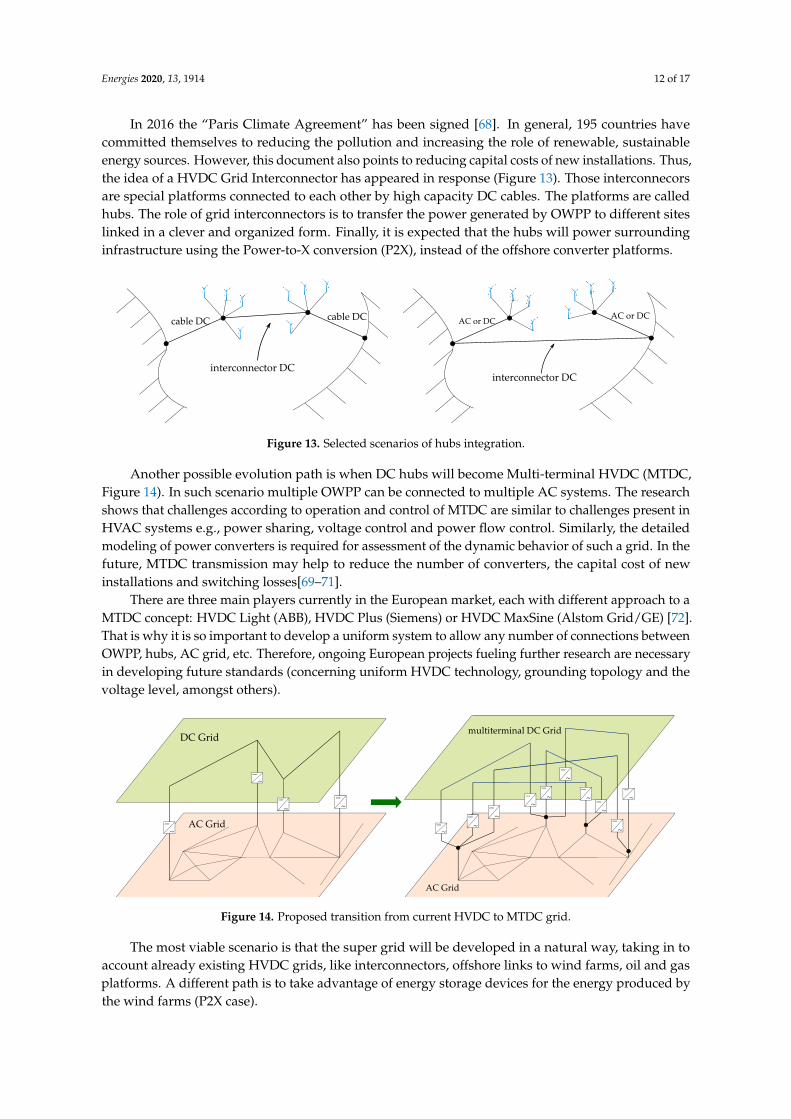
Another possible evolution path is when DC hubs will become Multi-terminal HVDC (MTDC,Figure 14). In such scenario multiple OWPP can be connected to multiple AC systems. The researchshows that challenges according to operation and control of MTDC are similar to challenges present inHVAC systems e.g., power sharing, voltage control and power flow control. Similarly, the detailedmodeling of power converters is required for assessment of the dynamic behavior of such a grid. In thefuture, MTDC transmission may help to reduce the number of converters, the capital cost of newinstallations and switching losses[69–71].
There are three main players currently in the European market, each with different approach to aMTDC concept: HVDC Light (ABB), HVDC Plus (Siemens) or HVDC MaxSine (Alstom Grid/GE) [72].That is why it is so important to develop a uniform system to allow any number of connections betweenOWPP, hubs, AC grid, etc. Therefore, ongoing European projects fueling further research are necessaryin developing future standards (concerning uniform HVDC technology, grounding topology and thevoltage level, amongst others).
Figure 14. Proposed transition from current HVDC to MTDC grid.
The most viable scenario is that the super grid will be developed in a natural way, taking in toaccount already existing HVDC grids, like interconnectors, offshore links to wind farms, oil and gasplatforms. A different path is to take advantage of energy storage devices for the energy produced bythe wind farms (P2X case).

Energies 2020, 13, 1914 13 of 17
Power-to-X or P2X is a concept relying on conversion of electricity into an energy carrier ina form of heat, product or basic substance. It is a broad term for different ways of generatingenergy, namely power-to-gas, power-to-liquid, power-to-fuel, power-to-chemicals, power-to-heat andpower-to-mobility. P2X provides the possibility to create long-term storage options and substitutehydrogen, methane and other synthetic fuels for fossil energy sources in transportation, chemicalprocessing and heat production.
Disadvantages of P2X combined with OWPP include high investment costs and energy losses dueto low overall efficiency of conversion process. Several authors conclude that in P2G case, hydrogenproduced from wind energy should be sold, as re-electrification is exceptionally expensive. Futureresearch works should be focused on the reduction of implementation and maintenance costs for theP2X to become a viable scenario of OWPP integration [73–75].
Another scenario addressing the intermittency of renewable energy sources might be compressedair energy storage (CAES) coupled with an OWPP. An interesting implementation of such approach isFLASC project, where energy is stored using a hydro-pneumatic liquid piston, driven by a reversiblepump-turbine. The FLASC is exploiting the hydro-static pressure of the deeper sea region to preservea stable pressure in the CAS, which is independent of the state-of-charge. As it integrates into anexisting offshore floating platform framework, it is treated as a viable solution.
The project created by University of Malta is currently at the stage of a large-scale demonstratorat the open sea [73,76].
5. Conclusions
The increase in participation of HVDC technology in modern power systems is strongly relatedto the development of power electronic devices across the last decades. The nominal parameters ofmodern HVDC systems reach MV of DC voltage, tens of GW of installed power while improvingon the reliability and robustness of the built systems. In addition to the well-known LCC topology(which remain to represent the largest share of the converters used in the HVDC transmission market),there is an increase in the number of VSC MMC topology applications. Moreover, hybrid topologies,which are derivatives of Modular Multilevel Converters, are currently under intensive development.
The development of new offshore wind power plants has slowed down slightly according todata from 2018 (partly due to the increased interest in the Photo-voltaic farms) [8]. Nevertheless, newOWPPs are still being built, e.g., Thor—2020 Tender with 1000 MW capacity. Only high power OWPPare currently constructed to adjust to the evolving energy market. To follow those trends, the offshoreenergy market will promote innovations in the HVDC technology. This will provide more stable andgreener OWPPs offering a higher degree of controllability.
Authors believe that the development of offshore wind power plants, an increasing number ofDC transmission systems including classic point-to-point HVDC, DC hubs and multi-terminal HVDCwill create a DC super grid in the future. This claim is evidenced by a noticeable intensification ofresearch work concerning those complex systems.
The paper shows that technological advancements in the last 10 years enable higher waterdepths and increased distances to shore for new OWPPs. The new break-even-distance for offshoreinstallations is proposed. The advantages of HVDC over HVAC technology in relation to transmissiondistance are given. The authors attempt to describe and summarize the HVDC offshore transmission.The different HVDC configurations and topologies of HVDC converters are elucidated. Finally, thefuture solutions and possible development paths are also suggested.
Author Contributions: Conceptualization, R.R.; formal analysis, R.R.; investigation, R.R. and Ł.S.; resources, R.R.;writing—original draft preparation, R.R.; writing—review and editing, Ł.S.; visualization, R.R.; supervision, Ł.S.;project administration, R.R. and Ł.S. All authors have read and agreed to the published version of the manuscript.
Funding: This research received no external funding.
Conflicts of Interest: The authors declare no conflict of interest.

Energies 2020, 13, 1914 14 of 17
References
1. Bahrman, M.P.; Johnson, B.K. The ABCs of HVDC Transmission Technologies. IEEE Power Energy Mag. 2007,5, 32–44. [CrossRef]
2. Jovcic, D.; van Hertem, D.; Linden, K.; Taisne, J.; Grieshaber, W. Feasibility of DC Transmission Networks.In Proceedings of the 2011 2nd IEEE PES International Conference and Exhibition on Innovative Smart GridTechnologies, Manchester, UK, 5–7 December 2011; pp. 1–8. [CrossRef]
3. Bresesti, P.; Kling, W.L.; Hendriks, R.L.; Vailati, R. HVDC Connection of Offshore Wind Farms to theTransmission System. IEEE Trans. Energy Convers. 2007, 22, 37–43. [CrossRef]
4. Shao, S.J.; Agelidis, V.G. Review of DC System Technologies for Large Scale Integration of Wind EnergySystems with Electricity Grids. Energies 2010, 3, 1303–1319. [CrossRef]
5. Brenna, M.; Foiadelli, F.; Longo, M.; Zaninelli, D. Improvement of Wind Energy Production through HVDCSystems. Energies 2017, 10, 157. [CrossRef]
6. Intelligence, W.B. The European Offshore Wind Industry—Key Trends and Statistics 2016. Available online:https://winrope-Annual-Offshore-Statistics-2016.pdf (accessed on 10 April 2020).
7. Pineda, I. The European offshore wind industry key 2017 trends and statistics. Wind Eur. 2017, 31. [CrossRef]8. Selot, F.; Fraile, D.; Brindley, G.; Walsh, C. Offshore Wind in Europe: Key trends and statistics 2018. Refocus
2018, 1–37. [CrossRef]9. Renewables—Fuels & Technologies; IEA. Available online: https://www.iea.org/fuels-and-technologies/r
enewables (accessed on 10 April 2020) .10. IEA Online Data Services. Renewables Information. Available online: https://www.iea.org/fuels-and-tech
nologies/electricity (accessed on 10 April 2020) .11. Kutt, F.; Michna, M.; Kostro, G. Multiple reference frame theory in the synchronous generator model
considering harmonic distortions caused by nonuniform pole shoe saturation. IEEE Trans. Energy Convers.2020, 35, 166–173. [CrossRef]
12. Barker, C.D.; Davidson, C.C.; Trainer, D.R.; Whitehouse, R.S. Requirements of DC-DC converters to facilitatelarge DC grids. In Proceedings of the 44th International Conference on Large High Voltage Electric Systems,Paris, France, 26–31 August 2012.
13. Komusanac, I.; Fraile, D.; Brindley, G. Wind Energy in Europe in 2018. Trends and Statistics; WindEurope:Brussels, Belgium, 2019.
14. Purta, M.; Marciniak Tomasz, T.; Rozenbaum, K. Report: ”Developing offshore wind power in Poland”;McKinsey & Company: Warszawa, Poland, 2016.
15. The European Offshore Wind Industry—Key Trends and Statistics 2017. 2018. Available online: https://winindustry-key-trends-statistics-2017/ (accessed on 10 April 2020).
16. Maneiro, J.; Ryndzionek, R.; Lagier, T.; Dworakowski, P.; Buttay, C. Design of a SiC based Triple ActiveBridge cell for a multi-megawatt DC-DC converter. In Proceedings of the 2017 19th European Conferenceon Power Electronics and Applications (EPE’17 ECCE Europe), Warsaw, Poland, 11–14 September 2017;pp. P.1–P.10. [CrossRef]
17. Mahmoudi, H.; Aleenejad, M.; Ahmadi, R. Modulated Model Predictive Control of Modular MultilevelConverters in VSC-HVDC Systems. IEEE Trans. Power Deliv. 2018, 33, 2115–2124. [CrossRef]
18. Meah, K.; Ula, S. Comparative evaluation of HVDC and HVAC transmission systems. In Proceedings of the2007 IEEE Power Engineering Society General Meeting, Tampa, FL, USA, 24–28 June 2007. [CrossRef]
19. Zhang, Y.; Ravishankar, J.; Fletcher, J.; Li, R.; Han, M. Review of modular multilevel converter basedmulti-terminal HVDC systems for offshore wind power transmission. Renew. Sustain. Energy Rev. 2016,61, 572–586. [CrossRef]
20. List of HVDC Projects. 2019. Available online: https://ipfs.io/ipfs/QmXoyo6uco/wiki/List_of_HVDC_projects.html (accessed on 10.04.2020).
21. Paez, J.D.; Frey, D.; Maneiro, J.; Bacha, S.; Dworakowski, P. Overview of DC-DC Converters dedicated toHVDC Grids. IEEE Trans. Power Deliv. 2019, 34, 119–128. [CrossRef]
22. Xiang, X.; Zhang, X.; Chaffey, G.P.; Green, T.C. An Isolated Resonant Mode Modular Converter With FlexibleModulation and Variety of Configurations for MVDC Application. IEEE Trans. Power Deliv. 2018, 33, 508–519.[CrossRef]

Energies 2020, 13, 1914 15 of 17
23. HVDC Technology for Offshore Wind Is Maturing. 2018. Available online: https://new.abb.com/news/detail/8270/hvdc-technology-for-offshore-wind-is-maturingl (accessed on 10 April 2020).
24. R. Liu. Long-Distance DC Electrical Power Transmission. IEEE Electr. Insul. Mag. 2013, 29, 37–46. [CrossRef]25. Liu, R. Progress of Long-Distance DC Electrical Power Transmission. In Proceedings of the 2017 1st
International Conference on Electrical Materials and Power Equipment (ICEMPE), Xi’an, China, 14–17 May2017; pp. 93–96. [CrossRef]
26. Ahmed, K.; Jovcic, D. High Voltage Direct Current Transmission: Converters, Systems and DC Grids; Wiley:Hoboken, NJ, USA, 2015; p. 438. [CrossRef]
27. Blasco-Gimenez, R.; Anó-Villalba, S.; Rodriguez-D’Derlée, J.; Bernal-Perez, S.; Morant, F. Diode-Based HVdcLink for the Connection of Large Offshore Wind Farms. IEEE Trans. Energy Convers. 2011, 26, 615–626.[CrossRef]
28. Akhmatov, V.; Callavik, M.; Franck, C.M.; Rye, S.E.; Ahndorf, T.; Bucher, M.K.; Müller, H.; Schettler, F.;Wiget, R. Technical Guidelines and Prestandardization Work for First HVDC Grids. IEEE Trans. Power Deliv.2014, 29, 327–335. [CrossRef]
29. Kouro, S.; Malinowski, M.; Gopakumar, K.; Pou, J.; Franquelo, L.G.; Wu, B.; Rodriguez, J.; Perez, M.A.;Leon, J.I. Recent advances and industrial applications of multilevel converters. IEEE Trans. Ind. Electron.2010, 57, 2553–2580. [CrossRef]
30. Alassi, A.; Bañales, S.; Ellabban, O.; Adam, G.; MacIver, C. HVDC Transmission: Technology Review,Market Trends and Future Outlook. Renew. Sustain. Energy Rev. 2019, 112, 530–554. [CrossRef]
31. Pierri, E.; Binder, O.; Hemdan, N.G.; Kurrat, M. Challenges and opportunities for a European HVDC grid.Renew. Sustain. Energy Rev. 2017, 70, 427–456. [CrossRef]
32. Martinez-Rodrigo, F.; Ramirez, D.; Rey-Boue, A.; de Pablo, S.; Herrero-de Lucas, L. Modular MultilevelConverters: Control and Applications. Energies 2017, 10, 1709. [CrossRef]
33. Asplund, G.; Eriksson, K.; Svensson, K. DC Transmission based on Voltage Source Converters. In Proceedingsof the CIGRE SC14 Colloquium, Johannesburg, South Africa, 29–30 September 1997; pp. 1–7.
34. Keshavarz, S. Design and Evaluation of an Active Rectifier for a 4.1 MW Off-Shore Wind Turbine. 2011.Available online: http://studentarbeten.chalmers.se (accessed on 10 April 2020).
35. Dambone Sessa.; Chiarelli.; Benato. Availability Analysis of HVDC-VSC Systems: A Review. Energies 2019,12, 2703. [CrossRef]
36. Zhang, Z.; Xu, Z.; Xue, Y.; Tang, G. DC-Side Harmonic Currents Calculation and DC-Loop ResonanceAnalysis for an LCC-MMC Hybrid HVDC Transmission System. IEEE Trans. Power Deliv. 2015, 30, 642–651.[CrossRef]
37. Fu, Y.; Wang, C.; Tian, W.; Shahidehpour, M. Integration of Large-Scale Offshore Wind Energy via VSC-HVDCin Day-Ahead Scheduling. IEEE Trans. Sustain. Energy 2016, 7, 535–545. [CrossRef]
38. Morawiec, M. The adaptive backstepping control of permanent magnet synchronous motor supplied bycurrent source inverter. IEEE Trans. Ind. Inform. 2013, 9, 1047–1055. [CrossRef]
39. Morawiec, M.; Lewicki, A. Power electronic transformer based on cascaded H-bridge converter. Bull. Pol.Acad. Sci. Tech. Sci. 2017, 65, 675–683. [CrossRef]
40. Dworakowski, P.; Wilk, A.; Michna, M.; Lefebvre, B.; Sixdenier, F.; Mermet-Guyennet, M. Effective Permeabilityof Multi Air Gap Ferrite Core 3-Phase Medium Frequency Transformer in Isolated DC-DC Converters. Energies2020, 13, 1352. [CrossRef]
41. Marquardt, R.; Lesnicar, A. A new modular voltage source inverter topology. In Proceedings of theEuropean Conference on Power Electronics and Applications (EPE2003), Toulouse, France, 2–4 September2003; pp. 1–10.
42. Abildgaard, E.N.; Molinas, M. Modelling and Control of the Modular Multilevel Converter (MMC);Energy Procedia; Elsevier Ltd.: Amsterdam, The Netherlands, 2012; Voluume 20, pp. 227–236. [CrossRef]
43. Jones, P.S.; Davidson, C.C. Calculation of power losses for MMC-based VSC HVDC stations. In Proceedingsof the 2013 15th European Conference on Power Electronics and Applications (EPE), Lille, France,2–6 September 2013. [CrossRef]
44. Mayordomo, J.G.; Beites, L.F.; Yang, X.; Xu, W. A Detailed Procedure for Harmonic Analysis of Three-PhaseDiode Rectifiers Under Discontinuous Conduction Mode and Nonideal Conditions. IEEE Trans. Power Deliv.2018, 33, 741–751. [CrossRef]

Energies 2020, 13, 1914 16 of 17
45. Kuhn, O.; Menke, P.; Rainer, Z.; Timo, C.; Brogn, P.; Thisted, J.; Goldenbaum, N. 2nd Generation DC GridAccess for Offshore Wind Farms: “HVDC in an AC Fashion”. 2016. Available online: http://www.ptd.siemens.de/CIGRE2016_B3-110_2nd_generation_DC_GridAccess.pdf (accessed on 10 April 2020).
46. Seman, S.; Tuan Trinh, N.; Zurowski, R.; Kreplin, S. Modeling of the Diode-Rectifier Based HVDCTransmission Solution for Large Offshore Wind Power Plants Grid Access. In Proceedings of the InternationalWorkshop on Large-Scale Integration of Wind Power into Power Systems as well as on TransmissionNetworks for Offshore Wind Power Plants, Vienna, Austria, 15–17 November 2016.
47. Yu, L.; Li, R.; Xu, L. Distributed PLL-Based Control of Offshore Wind Turbines Connected WithDiode-Rectifier-Based HVDC Systems. IEEE Trans. Power Deliv. 2018, 33, 1328–1336. [CrossRef]
48. Manikam, V.R.; Cheong, K.Y. Die Attach Materials for High Temperature Applications: A Review. IEEE Trans.Compon. Packag. Manuf. Technol. 2011, 1, 457–478. [CrossRef]
49. Yang, Y.; Davari, P.; Zare, F.; Blaabjerg, F. Enhanced Phase-Shifted Current Control for Harmonic Cancellationin Three-Phase Multiple Adjustable Speed Drive Systems Yongheng. IEEE Trans. Power Deliv. 2017,32, 996–1004. [CrossRef]
50. Añó-Villalba, S.; Bernal-Perez, S.; Pena, R.; Vidal-Albalate, R.; Belenguer, E.; Aparicio, N.; Blasco-Gimenez, R.24-Pulse Rectifier for Harmonic Management in HVDC Diode Rectifier Wind Power Plants. In Proceedingsof the 12th IET International Conference on AC and DC Power Transmission (ACDC 2016), Beijing, China,28–29 May 2016; pp. 1–6. [CrossRef]
51. Sleszynski, W.; Cichowski, A.; Mysiak, P. Current Harmonic Controller in Multiple Reference Frames forSeries Active Power Filter Integrated with 18-Pulse Diode Rectifier. Bull. Pol. Acad. Sci. Tech. Sci. 2018,66, 699–704. [CrossRef]
52. Mysiak, P.; Sleszynski, W.; Cichowski, A. Experimental Test Results of the 150 kVA 18-Pulse Diode Rectifierwith Series Active Power Filter. In Proceedings of the 2016 10th International Conference on Compatibility,Power Electronics and Power Engineering (CPE-POWERENG), Bydgoszcz, Poland, 29 June–1 July 2016;pp. 380–383. [CrossRef]
53. Strzelecki, R.; Mysiak, P. A Robust 18-Pulse Diode Rectifier with Coupled Reactors. Bull. Polish Acad. Sci.Tech. Sci. 2011, 59, 541–550. [CrossRef]
54. Chiniforoosh, S.; Atighechi, H.; Davoudi, A.; Jatskevich, J.; Yazdani, A.; Filizadeh, S.; Saeedifard, M.;Martinez, J.A.; Sood, V.; Strunz, K.; Mahseredjian, J.; Dinavahi, V. Dynamic Average Modeling of Front-EndDiode Rectifier Loads Considering Discontinuous Conduction Mode and Unbalanced Operation. IEEE Trans.Power Deliv. 2012, 27, 421–429. [CrossRef]
55. Kirby, N.M.; Xu, L.; Luckett, M.; Siepmann, W. HVDC Transmission for Large Offshore Wind Farms.Power Eng. J. 2002, 16, 135–141. [CrossRef]
56. Blecharz, K.; Wachowiak, D.; Krzemiski, Z. A novel speed observer for doubly-fed induction generator.In Proceedings of the 2017 19th European Conference on Power Electronics and Applications (EPE’17 ECCEEurope), Warsaw, Poland, 11–14 September 2017. [CrossRef]
57. Amber, L.; Haddad, K. Hybrid Si IGBT-SiC Schottky Diode Modules for Medium to High Power Applications.In Proceedings of the 2017 IEEE Applied Power Electronics Conference and Exposition (APEC), Tampa, FL,USA, 26–30 March 2017; pp. 3027–3032. [CrossRef]
58. Chang, Y.; Cai, X. Hybrid Topology of a Diode-Rectifier-Based HVDC System for Offshore Wind Farms.IEEE J. Emerg. Sel. Top. Power Electron. 2019, 7, 2116–2128. [CrossRef]
59. Torres-Olguin, R.E.; Molinas, M.; Undeland, T. Hybrid HVDC connection of large offshore wind farms tothe AC grid. In Proceedings of the 2012 IEEE International Symposium on Industrial Electronics, Hangzhou,China, 28–31 May 2012; pp. 1591–1597. [CrossRef]
60. Zhang, X.; Wu, Z.; Hu, M.; Li, X.; Lv, G. Coordinated Control Strategies of VSC-HVDC-Based Wind PowerSystems for Low Voltage Ride Through. Energies 2015, 8, 7224–7242. [CrossRef]
61. Lebre, J.; Portugal, P.; Watanabe, E. Hybrid HVDC (H2VDC) System Using Current and Voltage SourceConverters. Energies 2018, 11, 1323. [CrossRef]
62. Veilleux, E.; Lehn, P.W. Interconnection of direct-drive wind turbines using a series-connected dc grid.IEEE Trans. Sustain. Energy 2014, 5, 139–147. [CrossRef]
63. Nguyen, T.H.; Lee, D.; Kim, C. A Series-Connected Topology of a Diode Rectifier and a Voltage-SourceConverter for an HVDC Transmission System. IEEE Trans. Power Electron. 2014, 29, 1579–1584. [CrossRef]

Energies 2020, 13, 1914 17 of 17
64. Nguyen, T.H.; Lee, D.C. Control of offshore wind farms based on HVDC. In Proceedings of the 2012IEEE Energy Conversion Congress and Exposition (ECCE), Raleigh, NC, USA, 15–20 September 2012;pp. 3113–3118. [CrossRef]
65. Nguyen, T.H.; Lee, D.C.; Kim, C.K. A cost-effective converter system for HVDC links integrated withoffshore wind farms. In Proceedings of the IECON 2013—39th Annual Conference of the IEEE IndustrialElectronics Society, Vienna, Austria, 10–13 November 2013; pp. 7978–7983. [CrossRef]
66. De Prada Gil, M.; Domínguez-García, J.L.; Díaz-González, F.; Aragüés-Peñalba, M.; Gomis-Bellmunt, O.Feasibility Analysis of Offshore Wind Power Plants with DC Collection Grid. Renew. Energy 2015, 78, 467–477.[CrossRef]
67. Entsoe. European Network of Transmission System Operators for DSR. Eur. Electr. Grid Initiat. Roadmap2018, 18, 20.
68. Rogelj, J.; Den Elzen, M.; Höhne, N.; Fransen, T.; Fekete, H.; Winkler, H.; Schaeffer, R.; Sha, F.; Riahi, K.;Meinshausen, M. Paris Agreement climate proposals need a boost to keep warming well below 2 C. Nature2016, 534, 631–639. [CrossRef]
69. Chen, C.; Luo, F.; Kang, Y. A Review of SiC Power Module Packaging: Layout, Material System andIntegration. CPSS Trans. Power Electron. Appl. 2017, 2, 170–186. [CrossRef]
70. Rodriguez, P.; Rouzbehi, K. Multi-terminal DC grids: challenges and prospects. J. Mod. Power Syst.Clean Energy 2017, 5, 515–523. [CrossRef]
71. Hwang, S.; Song, S.; Jang, G.; Yoon, M. An Operation Strategy of the Hybrid Multi-Terminal HVDC forContingency. Energies 2019, 12, 2042. [CrossRef]
72. Hertem, D.V.A.N.; Gomis-Bellmunt, O.; Liang, J.U.N. HVDC Grids: For Offshore and Supergrid of The Future;John Wiley & Sons Inc.: Hoboken, NJ, USA, 2016; p. 528. [CrossRef]
73. Fernández-Guillamón, A.; Das, K.; Cutululis, N.A.; Molina-García, Á. Offshore Wind Power Integration intoFuture Power Systems: Overview and Trends. J. Mar. Sci. Eng. 2019, 7, 399. [CrossRef]
74. Schuster, M.; Walther, T. Valuation of combined wind power plant and hydrogen storage: A decision treeapproach. In Proceedings of the 2017 14th International Conference on the European Energy Market (EEM),Dresden, Germany, 6–9 June 2017. [CrossRef]
75. Wulf, C.; Linßen, J.; Zapp, P. Review of Power-To-Gas Projects in Europe; Energy Procedia; Elsevier Ltd.:Amsterdam, The Netherlands, 2018; Volume 155, pp. 367–378. [CrossRef]
76. Offshoreenergystorage. Renewable Energy Storage. 2019. Available online: https://www.offshoreenergystorage.com/ (accessed on 10 April 2020).
c© 2020 by the authors. Licensee MDPI, Basel, Switzerland. This article is an open accessarticle distributed under the terms and conditions of the Creative Commons Attribution(CC BY) license (http://creativecommons.org/licenses/by/4.0/).