ER41 PROFIBUS DP Manual -...
102
Altivar Process 900 ER41 PROFIBUS DP Manual 05/2017
Transcript of ER41 PROFIBUS DP Manual -...

Altivar Process 900
ER41 PROFIBUS DP Manual
05/2017

2
The information provided in this documentation contains general descriptions and/or technical characteristics of the
performance of the products contained herein. This documentation is not intended as a substitute for and is not to be
used for determining suitability or reliability of these products for specific user applications. It is the duty of any such user
or integrator to perform the appropriate and complete risk analysis, evaluation and testing of the products with respect to
the relevant specific application or use thereof. Neither BLEMO nor any of its affiliates or subsidiaries shall be
responsible or liable for misuse of the information contained herein. If you have any suggestions for improvements or
amendments or have found errors in this publication, please notify us.
No part of this document may be reproduced in any form or by any means, electronic or mechanical, including
photocopying, without express written permission of BLEMO.
All pertinent state, regional, and local safety regulations must be observed when installing and using this product. For
reasons of safety and to help ensure compliance with documented system data, only the manufacturer should perform
repairs to components.
When devices are used for applications with technical safety requirements, the relevant instructions must be followed.
Failure to use BLEMO software or approved software with our hardware products may result in injury, harm, or
improper operating results.
Failure to observe this information can result in injury or equipment damage.
© 2017 BLEMO. All rights reserved.

3
Safety Information . . . . . . . . . . . . . . . . . . . . . . . . . . . . . . . . . . . . . . . . . . . 5
About the Book. . . . . . . . . . . . . . . . . . . . . . . . . . . . . . . . . . . . . . . . . . . . . . 9
Chapter 1 Presentation . . . . . . . . . . . . . . . . . . . . . . . . . . . . . . . . . . . . . . . . . . . . . . . . 13
Hardware Overview. . . . . . . . . . . . . . . . . . . . . . . . . . . . . . . . . . . . . . . . . . . . . . . . . . . . . . . . 14
Software Overview . . . . . . . . . . . . . . . . . . . . . . . . . . . . . . . . . . . . . . . . . . . . . . . . . . . . . . . . 15
Chapter 2 Basics . . . . . . . . . . . . . . . . . . . . . . . . . . . . . . . . . . . . . . . . . . . . . . . . . . . . . 17
2.1 Introduction . . . . . . . . . . . . . . . . . . . . . . . . . . . . . . . . . . . . . . . . . . . . . . . . . . . . . . . . . . . . . . 18
Introduction . . . . . . . . . . . . . . . . . . . . . . . . . . . . . . . . . . . . . . . . . . . . . . . . . . . . . . . . . . . . . . 18
2.2 Common Additional Features . . . . . . . . . . . . . . . . . . . . . . . . . . . . . . . . . . . . . . . . . . . . . . . . 19
Identification and Maintenance Data . . . . . . . . . . . . . . . . . . . . . . . . . . . . . . . . . . . . . . . . . . . 20
I&M Record . . . . . . . . . . . . . . . . . . . . . . . . . . . . . . . . . . . . . . . . . . . . . . . . . . . . . . . . . . . . . . 21
2.3 PROFIdrive Parameters Channel . . . . . . . . . . . . . . . . . . . . . . . . . . . . . . . . . . . . . . . . . . . . . 22
PROFIdrive Profile. . . . . . . . . . . . . . . . . . . . . . . . . . . . . . . . . . . . . . . . . . . . . . . . . . . . . . . . . 23
Parameter Structure . . . . . . . . . . . . . . . . . . . . . . . . . . . . . . . . . . . . . . . . . . . . . . . . . . . . . . . 24
PROFIdrive Parameters . . . . . . . . . . . . . . . . . . . . . . . . . . . . . . . . . . . . . . . . . . . . . . . . . . . . 26
PROFIdrive Parameter Access . . . . . . . . . . . . . . . . . . . . . . . . . . . . . . . . . . . . . . . . . . . . . . . 27
Chapter 3 Hardware Setup . . . . . . . . . . . . . . . . . . . . . . . . . . . . . . . . . . . . . . . . . . . . . 29
Hardware Presentation . . . . . . . . . . . . . . . . . . . . . . . . . . . . . . . . . . . . . . . . . . . . . . . . . . . . . 30
Firmware and Description File. . . . . . . . . . . . . . . . . . . . . . . . . . . . . . . . . . . . . . . . . . . . . . . . 31
Installation of the Module. . . . . . . . . . . . . . . . . . . . . . . . . . . . . . . . . . . . . . . . . . . . . . . . . . . . 32
Electrical Installation . . . . . . . . . . . . . . . . . . . . . . . . . . . . . . . . . . . . . . . . . . . . . . . . . . . . . . . 33
Cable Routing Practices . . . . . . . . . . . . . . . . . . . . . . . . . . . . . . . . . . . . . . . . . . . . . . . . . . . . 35
Chapter 4 Software Setup . . . . . . . . . . . . . . . . . . . . . . . . . . . . . . . . . . . . . . . . . . . . . . 37
4.1 Basic Settings . . . . . . . . . . . . . . . . . . . . . . . . . . . . . . . . . . . . . . . . . . . . . . . . . . . . . . . . . . . . 38
Introduction . . . . . . . . . . . . . . . . . . . . . . . . . . . . . . . . . . . . . . . . . . . . . . . . . . . . . . . . . . . . . . 39
[Address] ( AdrC) . . . . . . . . . . . . . . . . . . . . . . . . . . . . . . . . . . . . . . . . . . . . . . . . . . . . . . 40
[Data rate used] ( bdrU) . . . . . . . . . . . . . . . . . . . . . . . . . . . . . . . . . . . . . . . . . . . . . . . . . 41
[PPO profile used] (PrFL). . . . . . . . . . . . . . . . . . . . . . . . . . . . . . . . . . . . . . . . . . . . . . . . 42
[DP Master Active] ( dPMA) . . . . . . . . . . . . . . . . . . . . . . . . . . . . . . . . . . . . . . . . . . . . . . . 43
4.2 Communication Profile . . . . . . . . . . . . . . . . . . . . . . . . . . . . . . . . . . . . . . . . . . . . . . . . . . . . . 44
Definition of a Profile . . . . . . . . . . . . . . . . . . . . . . . . . . . . . . . . . . . . . . . . . . . . . . . . . . . . . . . 45
Functional Profiles Supported by the Drive . . . . . . . . . . . . . . . . . . . . . . . . . . . . . . . . . . . . . . 46
Functional Description. . . . . . . . . . . . . . . . . . . . . . . . . . . . . . . . . . . . . . . . . . . . . . . . . . . . . . 47
CIA402 Operating State Diagram . . . . . . . . . . . . . . . . . . . . . . . . . . . . . . . . . . . . . . . . . . . . . 48
Description of Operating States. . . . . . . . . . . . . . . . . . . . . . . . . . . . . . . . . . . . . . . . . . . . . . . 49
Summary . . . . . . . . . . . . . . . . . . . . . . . . . . . . . . . . . . . . . . . . . . . . . . . . . . . . . . . . . . . . . . . . 51
Cmd Register ( CMd) . . . . . . . . . . . . . . . . . . . . . . . . . . . . . . . . . . . . . . . . . . . . . . . . . . . . . 52
Stop Commands . . . . . . . . . . . . . . . . . . . . . . . . . . . . . . . . . . . . . . . . . . . . . . . . . . . . . . . . . . 53
Assigning Control Word Bits . . . . . . . . . . . . . . . . . . . . . . . . . . . . . . . . . . . . . . . . . . . . . . . . . 54
[CIA402 State Reg] ( EtA) . . . . . . . . . . . . . . . . . . . . . . . . . . . . . . . . . . . . . . . . . . . . . . . . . 55
Starting Sequence. . . . . . . . . . . . . . . . . . . . . . . . . . . . . . . . . . . . . . . . . . . . . . . . . . . . . . . . . 56
Sequence for a Drive Powered by the Power Stage Supply . . . . . . . . . . . . . . . . . . . . . . . . . 57
Sequence for a Drive with Separate Control Stage. . . . . . . . . . . . . . . . . . . . . . . . . . . . . . . . 58
Sequence for a Drive with Mains Contactor Control . . . . . . . . . . . . . . . . . . . . . . . . . . . . . . . 61
Telegram 100, 101, 102, 106, 107 . . . . . . . . . . . . . . . . . . . . . . . . . . . . . . . . . . . . . . . . . . . . 63
Configuring Drive with a Siemens© S7-300 . . . . . . . . . . . . . . . . . . . . . . . . . . . . . . . . . . . . . 66
Configuration of Drive with the Telegram 100 . . . . . . . . . . . . . . . . . . . . . . . . . . . . . . . . . . . . 67
Configuring a Drive with the Telegram 101, 102, 106, or 107. . . . . . . . . . . . . . . . . . . . . . . . 68
Parameters Management with the Telegram 100, 101, 102, 106, 107 . . . . . . . . . . . . . . . . . 69
Table of Contents

4
Telegram 1. . . . . . . . . . . . . . . . . . . . . . . . . . . . . . . . . . . . . . . . . . . . . . . . . . . . . . . . . . . . . . . 73
State Diagram . . . . . . . . . . . . . . . . . . . . . . . . . . . . . . . . . . . . . . . . . . . . . . . . . . . . . . . . . . . . 74
Command Word and Operating State Word . . . . . . . . . . . . . . . . . . . . . . . . . . . . . . . . . . . . . 75
Reference Frequency. . . . . . . . . . . . . . . . . . . . . . . . . . . . . . . . . . . . . . . . . . . . . . . . . . . . . . . 78
4.3 Fieldbus Integration Tutorial. . . . . . . . . . . . . . . . . . . . . . . . . . . . . . . . . . . . . . . . . . . . . . . . . . 79
Fieldbus Integration Tutorial. . . . . . . . . . . . . . . . . . . . . . . . . . . . . . . . . . . . . . . . . . . . . . . . . . 79
Chapter 5 Operation . . . . . . . . . . . . . . . . . . . . . . . . . . . . . . . . . . . . . . . . . . . . . . . . . . 83
5.1 Operating States . . . . . . . . . . . . . . . . . . . . . . . . . . . . . . . . . . . . . . . . . . . . . . . . . . . . . . . . . . 84
Configuring Communication Error Response. . . . . . . . . . . . . . . . . . . . . . . . . . . . . . . . . . . . . 84
5.2 Operating Modes . . . . . . . . . . . . . . . . . . . . . . . . . . . . . . . . . . . . . . . . . . . . . . . . . . . . . . . . . . 85
Configuring the Control Channel . . . . . . . . . . . . . . . . . . . . . . . . . . . . . . . . . . . . . . . . . . . . . . 86
Configuration of the Drive for Operation in I/O Profile . . . . . . . . . . . . . . . . . . . . . . . . . . . . . . 87
Configuration of the Drive for Operation with CiA 402 Profile in Combined Mode. . . . . . . . . 88
Configuration of the Drive for Operation with CiA 402 Profile in Separate Mode. . . . . . . . . . 89
Chapter 6 Diagnostic and Troubleshooting . . . . . . . . . . . . . . . . . . . . . . . . . . . . . . . 91
Fieldbus Status LEDs. . . . . . . . . . . . . . . . . . . . . . . . . . . . . . . . . . . . . . . . . . . . . . . . . . . . . . . 92
Connection for Fieldbus Mode . . . . . . . . . . . . . . . . . . . . . . . . . . . . . . . . . . . . . . . . . . . . . . . . 93
Fieldbus Function Test. . . . . . . . . . . . . . . . . . . . . . . . . . . . . . . . . . . . . . . . . . . . . . . . . . . . . . 94
Communication Interruption. . . . . . . . . . . . . . . . . . . . . . . . . . . . . . . . . . . . . . . . . . . . . . . . . . 95
Monitoring of Communication Channel . . . . . . . . . . . . . . . . . . . . . . . . . . . . . . . . . . . . . . . . . 97
Control-Signal Diagnostics. . . . . . . . . . . . . . . . . . . . . . . . . . . . . . . . . . . . . . . . . . . . . . . . . . . 99
Glossary . . . . . . . . . . . . . . . . . . . . . . . . . . . . . . . . . . . . . . . . . . . . . . . . . . . . . . 101

5
Important Information
NOTICE
Read these instructions carefully, and look at the equipment to become familiar with the device before
trying to install, operate, or maintain it. The following special messages may appear throughout this
documentation or on the equipment to warn of potential hazards or to call attention to information that
clarifies or simplifies a procedure.
PLEASE NOTE
Electrical equipment should be installed, operated, serviced, and maintained only by qualified
personnel. No responsibility is assumed by BLEMO for any consequences arising out of the use of this
material.
A qualified person is one who has skills and knowledge related to the construction and operation of
electrical equipment and its installation, and has received safety training to recognize and avoid the
hazards involved.
Qualification Of Personnel
Only appropriately trained persons who are familiar with and understand the contents of this manual and
all other pertinent product documentation are authorized to work on and with this product. In addition,
these persons must have received safety training to recognize and avoid hazards involved. These
persons must have sufficient technical training, knowledge and experience and be able to foresee and
detect potential hazards that may be caused by using the product, by changing the settings and by the
mechanical, electrical and electronic equipment of the entire system in which the product is used. All
persons working on and with the product must be fully familiar with all applicable standards, directives,
and accident prevention regulations when performing such work.
Safety Information

6
Intended Use
This product is a drive for three-phase synchronous and asynchronous motors and intended for industrial
use according to this manual.The product may only be used in compliance with all applicable safety
regulations and directives, the specified requirements and the technical data.Prior to using the product,
you must perform a risk assessment in view of the planned application. Based on the results, the
appropriate safety measures must be implemented.Since the product is used as a component in an entire
system, you must ensure the safety of persons by means of the design of this entire system (for example,
machine design). Any use other than the use explicitly permitted is prohibited and can result in hazards.
Electrical equipment should be installed, operated, serviced, and maintained only by qualified personnel.
Product Related Information
Read and understand these instructions before performing any procedure with this drive.
DANGER
HAZARD OF ELECTRIC SHOCK, EXPLOSION OR ARC FLASH
� Only appropriately trained persons who are familiar with and understand the contents of this manual
and all other pertinent product documentation and who have received safety training to recognize
and avoid hazards involved are authorized to work on and with this drive system. Installation,
adjustment, repair and maintenance must be performed by qualified personnel.
� The system integrator is responsible for compliance with all local and national electrical code
requirements as well as all other applicable regulations with respect to grounding of all equipment. � Many components of the product, including the printed circuit boards, operate with mains voltage.
Do not touch. Use only electrically insulated tools.
� Do not touch unshielded components or terminals with voltage present. � Motors can generate
voltage when the shaft is rotated. Prior to performing any type of work on the drive system, block the
motor shaft to prevent rotation. � AC voltage can couple voltage to unused conductors in the motor
cable. Insulate both ends of unused conductors of the motor cable.
� Do not short across the DC bus terminals or the DC bus capacitors or the braking resistor terminals.
� Before performing work on the drive system:
� Disconnect all power, including external control power that may be present. � Place a Do Not Turn
On label on all power switches. � Lock all power switches in the open position. � Wait 15 minutes
to allow the DC bus capacitors to discharge. The DC bus LED is not an indicator of the absence of
DC bus voltage that can exceed 800 Vdc.
Measure the voltage on the DC bus between the DC bus terminals (PA/+, PC/-) using a properly
rated voltmeter to verify that the voltage is <42 Vdc
� If the DC bus capacitors do not discharge properly, contact your local BLEMO representative. Do
not repair or operate the product.
� Install and close all covers before applying voltage.
Failure to follow these instructions will result in death or serious injury.
WARNING
UNEXPECTED MOVEMENT
Drive systems may perform unexpected movements because of incorrect wiring, incorrect settings,
incorrect data or other errors.
� Carefully install the wiring in accordance with the EMC requirements.
� Do not operate the product with unknown or unsuitable settings or data.
� Perform a comprehensive commissioning test.
Failure to follow these instructions can result in death, serious injury, or equipment damage.
Damaged products or accessories may cause electric shock or unanticipated equipment operation.

7
DANGER
ELECTRIC SHOCK OR UNANTICIPATED EQUIPMENT OPERATION
Do not use damaged products or accessories.
Failure to follow these instructions will result in death or serious injury.
Contact your local BLEMO sales office if you detect any damage whatsoever.
WARNING
LOSS OF CONTROL
� The designer of any control scheme must consider the potential failure modes of control
paths and, for critical control functions, provide a means to achieve a safe state during and after a
path failure.
Examples of critical control functions are emergency stop, overtravel stop, power outage and restart.
� Separate or redundant control paths must be provided for critical control functions.
� System control paths may include communication links. Consideration must be given to the
implications of unanticipated transmission delays or failures of the link.
� Observe all accident prevention regulations and local safety guidelines (1). � Each
implementation of the product must be individually and thoroughly tested for proper operation before
being placed into service.
Failure to follow these instructions can result in death, serious injury, or equipment damage.
(1) For USA: Additional information, refer to NEMA ICS 1.1 (latest edition), Safety Guidelines for the
Application, Installation, and Maintenance of Solid State Control and to NEMA ICS 7.1 (latest edition),
Safety Standards for Construction and Guide for Selection, Installation and Operation of Adjustable-
Speed Drive Systems.
NOTICE
DESTRUCTION DUE TO INCORRECT MAINS VOLTAGE
Before switching on and configuring the product, verify that it is approved for the mains voltage
Failure to follow these instructions can result in equipment damage.

8

9
At a Glance
Document Scope
The purpose of this document is to:
� Show you how to install the PROFIBUS DP fieldbus module on the drive.
� Show you how to configure the drive to use PROFIBUS DP fieldbus.
NOTE: Read and understand this document and all related documents (see below) before installing,
operating, or maintaining the drive.
Validity Note
This documentation is valid for the Altivar Process drives.
The technical characteristics of the devices described in this document also appear online. To access this
information online:
Step Action
1 Go to the BLEMO home page www.blemo.com.
2 In the Search box type the reference of a product or the name of a product
range. � Do not include blank spaces in the model number/product range.
� To get information on grouping similar modules, use asterisks (*).
3 If you entered a reference, go to the Product Datasheets search results and click on the reference that
interests you. If you entered the name of a product range, go to the Product Ranges search results and click on the
product range that interests you.
4 If more than one reference appears in the Products search results, click on the reference that interests
you.
5 Depending on the size of your screen, you may need to scroll down to see the data sheet.
6 To save or print a data sheet as a .pdf file, click Download XXX product datasheet.
The characteristics that are presented in this manual should be the same as those characteristics that
appear online. In line with our policy of constant improvement, we may revise content over time to improve
clarity and accuracy. If you see a difference between the manual and online information, use the online
information as your reference.
About the Book

10
Related Documents
Use your tablet or your PC to quickly access detailed and comprehensive information on all our products on
www.blemo.com

11
Terminology
The technical terms, terminology, and the corresponding descriptions in this manual normally use the terms
or definitions in the relevant standards.
In the area of drive systems this includes, but is not limited to, terms such as error, error message, failure,
fault, fault reset, protection, safe state, safety function, warning, warning message, and so on.
Among others, these standards include:
• IEC 61800 series: Adjustable speed electrical power drive systems
• IEC 61508 Ed.2 series: Functional safety of electrical/electronic/programmable electronic safety-related
• EN 954-1 Safety of machinery - Safety related parts of control systems
• EN ISO 13849-1 & 2 Safety of machinery - Safety related parts of control systems.
• IEC 61158 series: Industrial communication networks - Fieldbus specifications
• IEC 61784 series: Industrial communication networks - Profiles
• IEC 60204-1: Safety of machinery - Electrical equipment of machines – Part 1: General requirements
In addition, the term zone of operation is used in conjunction with the description of specific hazards, and is
defined as it is for a hazard zone or danger zone in the EC Machinery Directive (2006/42/EC) and in ISO
12100-1.
Also see the glossary at the end of this manual.

12
0 n
Chapter 1Presentation
Presentation
What Is in This Chapter?
This chapter contains the following topics:
Topic Page
Hardware Overview 14
Software Overview 15

13
Presentation
Hardware Overview
General
The VW3A3607 is a PROFIBUS DP fieldbus module that can be used in a PROFIBUS DP industrial fieldbus.
The module has a 9-pin female Sub-D connector for connection to the PROFIBUS DP network.
The figure shows the hardware presentation of the VW3A3607 PROFIBUS DP fieldbus module:

14
Software Overview
Compatibility
The communication module enables the integration of a variable speed drive into a PROFIBUS DP
fieldbus. This module offers the possibility to control its host drive in native profile or with the PROFIdrive
profile.
Profile Telegrams
Native drive profile (CiA®402) 100,101,102,106,107
I/O profile 100,101,102,106,107
PROFIdrive 1
Fieldbus Module Features Overview
There are six modes of operation which are telegram 1, 100, 101, 102, 106, and 107. The telegram 1 is
based on the PROFIdrive V4.1 application profile part of the IEC 61800-7. The other telegrams are based
on the native profile of the drive.
Data is exchanged in order to make use of all the drive functions.
The following features are supported by the PROFIBUS DP module: � Four
configurable telegrams (Optimizes the I/Os usage of the master) � Mapping of
the process data from the master � Parameter management compliant with
PROFIdrive V4.1
� Baud rate from 9.6 to 12000 kbps (Automatic detection of the bus speed)
� Supports standard identification & maintenance requests
� Supports diagnostic data with VSD status (Variable speed drive status)
� Several DP V1 messaging modes
� Host drive can be handled from two masters (MS0 and MS1) � Quick
setup from drive side Presentation

15
Altivar Process 900 Basics
Chapter 2Basics
Basics
What Is in This Chapter?
This chapter contains the following sections:
Section Topic Page
2.1 Introduction 18
2.2 Common Additional Features 19
2.3 PROFIdrive Parameters Channel 22

Basics
16
IntroductionSection 2.1
Introduction
Introduction
PROFIBUS
PROFIBUS DP is the fast PROFIBUS version which is specially designed for communication in
production processes and for building automation. Features of PROFIBUS DP includes simple
connection of new devices in the bus and high transmission rates.
Device Identification
A master device uses the Ident number to identify the device class of the connected slave. The Ident
number is a unique number assigned to each device class by the PNO.
Slave Address
Each device on the network must be assigned a unique address from 1 to 126.
The master (normally address 0 ... 2) can communicate with each slave via this address.
PROFIBUS DP V1 Communication
PROFIBUS DP-V1 allows cyclic and acyclic communication between master and slave. Acyclic
communication is slower than cyclic communication, however it enables the modification of parameters
during operation.
The product supports acyclic communication as per PROFIBUS specification for MS0 communication.
The product supports acyclic communication for DP-V1 as per PROFIBUS specification for MS1 and MS2
communication.
The following services are available for acyclic communication:
Service Master Class 1 Master Class 2
READ Read data set Read data set
WRITE Write data set Write data set
INITIATE − Connect to master C2
ABORT − Terminate connection to master C2 Common Additional Features

Basics
17
Section 2.2
Common Additional Features
What Is in This Section?
This section contains the following topics:
Topic Page
Identification and Maintenance Data 20
I&M Record 21

Basics
18
Identification and Maintenance Data
Overview
Identification & maintenance (I&M) is established through PNO
Supports the user during various scenarios of the device life cycle, such as:
� Configuration � Commissioning
� Repair and update � Operation
and visualization
NOTE: These fields are read only (index AFF0 hex).
The access to the identification & maintenance data can be achieved using the PROFIBUS DPV1
mechanisms (IEC 611458-6).
Basics
19
I&M Record
Description
The table provides the details of I&M record:
Champ Number of
Bytes Value Description
HEADER_MANUF_SPEC 10 bytes (string) Manufacturer-specific field
MANUFACTURER_ID 2 bytes 01 hex, 29 hex 129 hex: BLEMO
ORDER_ID 20 bytes Identification object ID 1 Commercial name of the drive
SERIAL_NUMBER 16 bytes Serial number C1P1, C1P2, C1P3, C1P4
HARDWARE_REVISION 2 bytes 10 hex, 00 hex −
SOFTWARE_REVISION 4 bytes ’V’, A, B, C A = MSB of software version B = LSB of software version C = MSB of software revision
REVISION_COUNTER 2 bytes xx hex, yy hex Rev xy
PROFILE_ID 2 bytes − Defined by the PNO (3A00...3AFF,
PROFIdrive)
PROFILE_SPECIFIC_TYPE 2 bytes − Profile specific number
IM_VERSION 2 bytes 01 hex, 02 hex Version I&M: 1.2
IM_SUPPORTED 2 bytes 00 hex, 01 hex Managed index I&M → I&M0

Basics
20
Section 2.3
PROFIdrive Parameters Channel
What Is in This Section?
This section contains the following topics:
Topic Page
PROFIdrive Profile 23
Parameter Structure 24
PROFIdrive Parameters 26
PROFIdrive Parameter Access 27

Basics
21
PROFIdrive Profile
Overview
When operated with the PROFIdrive profile, the drive parameters are organized as defined by PNU
numbering and addressing modes. However, for people who are familiar with the Altivar parameters,
this addressing mode keeps the native structure of the device (based on Modbus addressing). PNU is
numbered from 0...65535 and each PNU represents a parameter (from single type as words to complex
data structure or arrays). PROFIdrive parameters from PNU 900 ...PNU 999 are standardized, they are
described below. All others PNUs are manufacturer-specific.
In the case of this drive, parameters can be separated in two groups:
• Standardized PNUs (900...999)
• Drive parameters which are gathered in a single PNU entry point: PNU1000 and Modbus address as
subindex. It is also possible to access the parameters using the Modbus address as PNU for each
parameter (1001...59999) and 0 as subindex.
PROFIdrive Based on PROFIBUS
When the drive is operated in PROFIdrive profile, the parameter management takes benefit of the
PROFIBUS acyclic messaging features. With PROFIBUS, it is possible to exchange messages of
variable length between both masters (MS0 or MS1). These messages come in addition of the periodic
data exchange.
drive

Basics
22
Parameter Structure
PROFIdrive Telegram
The table describes the PROFIdrive header:
DU Byte Nr Request
Function code 0 −
Slot_num 1 0: global parameters
Index 2 47: Reserved for PROFIdrive
Length 3 Length of PROFIdrive parameter channel frame
Data 4...5 PROFIdrive parameter channel frame: check
PROFIdrive Parameter Structure
A parameter is defined with its PNU number from 1...65535.
Each parameter consists of 3 main areas:
� PWE: the value
� PBE: describes the parameter attributes
� Text area
The access to the 3 different areas of a parameter is specified by the attribute field of the parameter
request.
The following diagram summarizes the parameter model (For more information, refer to the profile drive
technology V4 standard).
The parameters and their sub parts are identified as follows:
PNU number + attribute 10 hex PWE + Sub index
20 hex PBE + Sub index
30 hex Text + Sub index
Detail of the PBE Attribute
The diagram describes the PBE attribute:

Basics
23
Drive Parameters
Each drive parameter can be represented according to the PNU standard structure. Drive parameters
are part of the PNU 1000 or can be accessed using the Modbus address as PNU number.
The table provides the possible values of a parameter according to the PNU properties:
Parameter Property Drive Implementation Example
PNU number 1000 −
Sub index Modbus address CMD address: 8501
PWE Value of the parameter 0...65535 −
PBE Describes an array of 65535 words Constant
Text − Drive parameter

Basics
24
PROFIdrive Parameters
PROFIdrive Standard Parameters
Parameters 900 to 999 are defined in accordance with the PROFIdrive profile.
The table describes the required parameters:
PNU Sub -ID Definition Data Type R/W Comments
900 − Controller > DO PNU900
contains the cyclical frame if supervisor handles the DO
− R Control telegram.
Image of PZD
907 − Controller < DO PNU900 contains the cyclical frame if supervisor
handles the DO
− R Status telegram.
Image of PZD
922 − Telegram selection UINT R 1,100,101,102,106,107
927 − Operation priority UINT R/W Enables control
928 − Control priority UINT R =1
930 − Operating mode UINT R =1
944 − Error message counter UINT R The value of PNU944 is incremented
each time an error is detected (+1 for
each new detected error)
947 − Error number UINT R This parameter contains the error code
value (error code = error number) of an
error detected by the drive.
963 − Actual baud rate UNIT R Current baud rate
964 − Drive unit identification
0 Manufacturer ID − R Defined by PNO (PROFIBUS
organization)
1 Drive unit String R This UNIT contains the value xx
commercial catalog number (character
string)
2 Version (drive) − R This parameter contains the firmware
version of the host drive XXyy version, IE
3 Firmware date (year) INT R −
4 Firmware date (day/month) INT R This parameter contains the firmware
date (day/month)
Sub index 5 and 6 are not available.
965 − Profile identification number
UINT R Profile identification numbers: Byte 1 = 03: PROFIdrive Byte 2 = 40: V4.01
980...989 − Number list of defined
parameter (mandatory
parameter + PNU1000)
UINT R −

Basics
25
PROFIdrive Parameter Access
Parameters Requests
There are 2 types of request: � Request parameter (parameters are PNU
number, attribute, and sub index) � Change parameter (parameters are
PNU number, attribute, and sub index)
These requests are able to manage one or more parameters or several attributes of one parameter. In
order to access to a specific attribute of a parameter, the request header contains: the PNU, the sub
index, and an attribute. This attribute defines whether the request mentions the value, the description
area, or the text area.
Parameter Reading
Request
Byte n+1 Byte n
Request data Request reference = 01 Request ID = 01
Axis = 01 hex Number of parameters = 01
Attribute = 10 hex * Number of elements = 01
PNU number = 3E8 hex
Sub index = C81 hex (3201) ETA Modbus address
*refers to field value (PWE), 20 hex refers to the description field (PBE) and 30 hex to the text field.
Response
Byte n+1 Byte n
Response header Request reference = 01 Request ID = 01
Axis = 01 hex Number of parameters = 01
Response data Format = 42 hex * Number of elements = 01
PNU value = xxxx hex (value of ETA)
*format 42 hex specified that the returned value is a WORD.
NOTE: byte 41 hex, word 42 hex, standard integer 03 hex, double word 43 hex.
Parameter Writing
Request
Byte n+1 Byte n
Request header Request reference = 01 Request ID = 02
Axis = 01 hex Number of parameters = 01
Parameter number Attribute = 10 hex * Number of elements = 01
PNU number = 3E8 hex
Sub index = 2329 hex (9001) ACC Modbus address
Parameter value Format = 42 hex Amount values = 01
Value = 50 (ACC is set to 5 s)
*refers to field value (PWE), 20 hex refers to the description field (PBE) and 30 hex to the text field.
Response
Byte n+1 Byte n
Response header Request reference = 01 Request ID = 02
Axis = 01 hex Number of parameters = 01

Basics
26
Request for Negative Response
The table lists the items of a negative response:
Byte n+1 Byte n
Request header Request reference = 01 Request ID = 82*
Axis = 01 hex Number of parameters = 01
Parameter number Format = error 44 hex * Number of values
Value 0x00: Impermissible PNU 0x01: Cannot change value 0x02: Low or high limit exceeded + sub index 0x03: Sub index detected error + sub index 0x04: No array 0x05: Incorrect data type 0x06: Setting not permitted + sub index 0x07: Cannot change description + sub index 0x09: No description 0x0B: No operation priority 0x0F: No text array available 0x11: Cannot execute the request. Reason not specified 0x14: Value impermissible 0x15: Response too long 0x16: Parameter address impermissible 0x17: Illegal format 0x18: Number of values inconsistent 0x19: Axis/DO nonexistent 0x20: Cannot change text 0x65: Invalid request reference 0x66: Invalid request ID 0x67: Invalid axis number / DO-ID 0x68: Invalid number of parameters 0x69: Invalid attribute 0x6B: Request too short
*for all negative responses the ID equals to response code or 80 hex.
With the sub index in addition to the detected error value, the total length of the answer is 10 bytes.

27
Altivar Process 900 Hardware Setup
Chapter 3Hardware Setup
Hardware Setup
What Is in This Chapter?
This chapter contains the following topics:
Topic Page
Hardware Presentation 30
Firmware and Description File 31
Installation of the Module 32
Electrical Installation 33
Cable Routing Practices 35

Hardware Setup
28
Hardware Presentation
PROFIBUS DP Fieldbus Module
The figure shows the PROFIBUS DP fieldbus module equipped with a Sub-D 9 connector:
1 Sub-D 9 connector

Hardware Setup
29
Firmware and Description File
Compatibility
The fieldbus module version 1.AIE01 and higher is compliant with all ER41 product range.
The associated GSD is named as the following example:
SE100E70.GSD

Hardware Setup
30
Installation of the Module
Before Starting
Verify that the catalog number printed on the label corresponds to the purchase order.
Remove the fieldbus module from its packaging and check that it has not been damaged in transit.
DANGER
ELECTRIC SHOCK OR UNANTICIPATED EQUIPMENT OPERATION
Do not use damaged products or accessories.
Failure to follow these instructions will result in death or serious injury.
Insertion of the Fieldbus Module
The table provides the procedure for insertion of the PROFIBUS DP fieldbus module in the drive:
Step Action
1 Ensure that the power is off.
2 Locate the fieldbus module slot (A) on the bottom of the control part.
3 Add the corresponding sticker on the LED front panel of the drive.
4 Insert the module.
5 Check that the module is correctly inserted and locked mechanically in the drive.
1 Slot A
Removal of the Fieldbus Module
The table provides the procedure for removal of the PROFIBUS DP fieldbus module from the drive:
Step Action
1 Ensure that the power is off.
2 Press the strip.
3 Remove the module while maintaining the strip pressed,

Hardware Setup
31
Electrical Installation
Pin Layout
The fieldbus module is equipped with a sub-D 9 female connector for the PROFIBUS DP connection.
Use only validated PROFIBUS connectors. The PROFIBUS connectors are suitable for connecting
the fieldbus signal. � Connect the PROFIBUS signals. � If the device is at the end of the network,
use a PROFIBUS connector with a terminating resistor. � Fasten the cables to the cable guide. The
cable guide is not a strain relief.
The table provides the pin out details of the sub-D 9 connector:
Pin Signal Meaning
1 Shield Shield protective earth ground
2 − Not connected
3 RxD/TxD-P Receive/Transmit-data-P
4 CNTR-P Control-P
5 DGND Data ground
6 VP Voltage plus
7 − Not connected
8 RxD/TxD-N Receive/Transmit-Data-N
9 − Not connected
Cable Specification
Cable specifications are as follows:
� Use equipotential bonding conductors. � Use pre-assembled cables to reduce
the wiring mistakes.
� Shield: both end grounded.
� Twisted-pair cable. � Verify that wiring, cables, and connected interfaces meet
the PELV requirements.
� The maximum cable length depends on the baud rate and the signal propagation
delay, that is, shorter bus cable for higher baud rate.
Data rate (kbps) 9.6 19.2 93.75 187.5 500 1500 3000 6000 12000
Distance m (ft.) 1200
(4000) 1200
(4000) 1200
(4000) 1000
(3300) 400
(1300) 200
(650) 100
(330) 100
(330) 100
(330)

Hardware Setup
32
Terminating Resistor
Both ends of the entire PROFIBUS DP network must be terminated with a terminating resistor. Use
PROFIBUS connectors with integrated terminating resistors at both ends of the network.
The schematic diagram shows the terminating resistor combination:

Hardware Setup
33
Cable Routing Practices
Installation Topology
The following figure shows an example of a wiring solution between a master and slaves using fieldbus
modules. The connector and cable for connection to the PROFIBUS DP network must be ordered
separately.

Hardware Setup
34

35
Altivar Process 900 Software Setup
Chapter 4Software Setup
Software Setup
What Is in This Chapter?
This chapter contains the following sections:
Section Topic Page
4.1 Basic Settings 38
4.2 Communication Profile 44
4.3 Fieldbus Integration Tutorial 79

Software Setup
36
Basic SettingsSection 4.1
Basic Settings
What Is in This Section?
This section contains the following topics:
Topic Page
Introduction 39
[Address] ( AdrC) 40
[Data rate used] ( bdrU) 41
[PPO profile used] (PrFL) 42
[DP Master Active] ( dPMA) 43

Software Setup
37
Introduction
Overview
The parameters are described according to the graphic display terminal. These settings are also possible
from commissioning software.

Software Setup
38
[Address] (AdrC)
About This Parameter
This parameter defines the PROFIBUS DP slave address.
Access
The parameter is accessible in the [Communication] ( COM) /[Comm Parameters] ( CMP) , [Profibus]
( PbC-) menu.
The parameter number is 6601
Possible Settings
Settings Code Value Description
[2...126] 2...126 2...126 PROFIBUS address
Factory setting: 126

Software Setup
39
[Data rate used] (bdrU)
About This Parameter
This parameter displays the current baud rate.
Access
The parameter is accessible in the [Display] ( Mon-) /[Communication map] ( CMM-) , [PROFIBUS
DIAG] ( Prb-) menu.
This is a read-only parameter
The parameter number is 6660
Possible Settings
Settings Code Value Description
[Automatic]] [9600 bps] [10 Kbps] [19200 bps] [45.45 Kbps] [93.75 Kbps] [187.5 Kbps ] [500 Kbps] [1.5 Mbps ] [3 Mbps] [6 Mbps] [12 Mbps]
AUtO 9K6 10K 19K2 45K4 93K7 187K 500 1M5 3M 6M 12M
4 28 30 32 37 42 54 68 80 82 83 88
Current baud rate Factory setting: Automatic

Software Setup
40
[PPO profile used] (PrFL)
About This Parameter
This parameter is used to select the actual profile for the device.
Access
The parameter is accessible in the [Display] ( Mon-) /[Communication map] ( CMM-) , [PROFIBUS
DIAG] ( Prb-) menu.
This is a read parameter.
The parameter number is 6665.
Possible Settings
The table presents the parameter settings:
Settings Code Value Description
[UnCG] [1] [100] [101] [102] [106] [107]
unCG 1 100 101 102 106 107
0 1 100 101 102 106 107
UNCFG Profidrive Device specific Device specific Device specific Device specific Device specific Factory setting: 0

Software Setup
41
[DP Master Active] (dPMA)
About This Parameter
This parameter displays the active PROFIBUS DP master.
Access
The parameter is accessible in the [Display] ( Mon-) /[Communication map] ( CMM-) , [PROFIBUS
DIAG] ( Prb-) menu.
This is a read-only parameter
The parameter number is 6666
Possible Settings
Settings Code Value Description
[MCL1]] [MCL2]
1 2
1 2
Active master Factory settings: 1
Software Setup
42
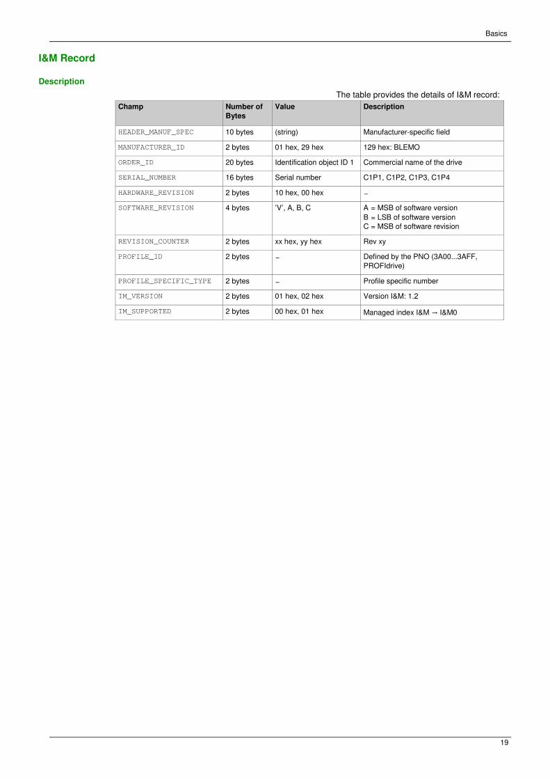
Communication ProfileSection 4.2
Communication Profile
What Is in This Section?
This section contains the following topics:
Topic Page
Definition of a Profile 45
Functional Profiles Supported by the Drive 46
Functional Description 47
CIA402 Operating State Diagram 48
Description of Operating States 49
Summary 51
Cmd Register ( CMd) 52
Stop Commands 53
Assigning Control Word Bits 54
[CIA402 State Reg] ( EtA) 55
Starting Sequence 56
Sequence for a Drive Powered by the Power Stage Supply 57
Sequence for a Drive with Separate Control Stage 58
Sequence for a Drive with Mains Contactor Control 61
Telegram 100, 101, 102, 106, 107 63
Configuring Drive with a Siemens© S7-300 66
Configuration of Drive with the Telegram 100 67
Configuring a Drive with the Telegram 101, 102, 106, or 107 68
Parameters Management with the Telegram 100, 101, 102, 106, 107 69
Telegram 1 73
State Diagram 74
Command Word and Operating State Word 75
Reference Frequency 78

Software Setup
43
Definition of a Profile
Types of Profiles
There are 3 types of profile:
� Communication profiles
� Functional profiles
� Application profiles
Communication Profile
A communication profile describes the characteristics of a bus or network:
� Cables
� Connectors
� Electrical characteristics
� Access protocol
� Addressing system
� Periodic exchange
service � Messaging
service � ...
A communication profile is unique to a type of fieldbus (such as Modbus, PROFIBUS DP, and so on) and
is used by different types of devices.
Functional Profile
A functional profile describes the behavior of a type of device:
� Functions
� Parameters (such as name, format, unit, type, and so on.)
� Periodic I/O variables � State chart � ...
A functional profile is common to all members of a device family (such as variable speed drives, encoders,
I/O modules, displays, and so on).
They can feature common or similar parts. The standardized (IEC 61800-7) functional profiles of variable
speed drives are: � CiA402 � PROFIDRIVE � CIP
DRIVECOM has been available since 1991.
CiA402 device profile for drives and motion control represents the next stage of this standard
development and is now part of the IEC 61800-7 standard.
Some protocols also support the Open DeviceNet Vendor Association profile (ODVA).
Application Profile
Application profile defines the services to be provided by the devices on a machine. For example, CiA
DSP 417-2 V 1.01 part 2: CANopen application profile for lift control systems - virtual device definitions.
Interchangeability
The aim of communication and functional profiles is to achieve interchangeability of the devices
connected via the fieldbus.

Software Setup
44
Functional Profiles Supported by the Drive
I/O Profile
Using the I/O profile simplifies PLC programming.
The I/O profile mirrors the use of the terminal strip for control by utilizing 1 bit to control a function.
The I/O profile for the drive can also be used when controlling via a fieldbus.The drive starts up as soon
as the run command is sent.15 bits of the control word (bits 1...15) can be assigned to a specific function.
This profile can be developed for simultaneous control of the drive via:
� The terminals � The Modbus
control word � The CANopen
control word � EtherNet/IP
embedded � The fieldbus module
control word
The I/O profile is supported by the drive itself and therefore in turn by all the communication ports
(integrated Modbus, CANopen, Ethernet, PROFIBUS DP, PROFINET, and DeviceNet fieldbus modules).
CiA402 Profile
The drive only starts up following a command sequence.
The control word is standardized.
5 bits of the control word (bits 11...15) can be assigned to a function.
The CiA402 profile is supported by the drive itself and therefore by all the communication ports (Modbus,
CANopen, Ethernet, PROFIBUS DP, PROFINET, and DeviceNet).
The drive supports the velocity mode of CiA402 profile.
In the CiA402 profile, there are two modes that are specific to the drive and characterize commands
and references value management: � Separate [Separate] (SEP) � Not separate [Not separ.]
(SIM),

Software Setup
45
Functional Description
Introduction
Drive operation involves two main functions, which are illustrated in the diagrams below.
CiA402
The main parameters are shown with their CiA402 name and their CiA402/Drivecom index (the values in
brackets are the CANopen addresses of the parameter).
The following figure shows the control diagram for drive operation:
Simplified diagram for speed control in Velocity mode:
ER41 Drive
These diagrams translate as follows for the ER41 drive.
The following figure shows the control diagram for drive operation:
Simplified diagram for speed control in Velocity mode:

Software Setup
46
CIA402 Operating State Diagram
State Diagram
After switching on and when an operating mode is started, the product goes through a number of
operating states.
The state diagram (state machine) shows the relationships between the operating states and the state
transitions. The operating states are internally monitored and influenced by monitoring functions.
The following figure shows the CIA402 state diagram:

Software Setup
47
Description of Operating States
Drive Operating State
The operating state of the drive changes depending on whether the control word [Cmd Register] (
CMd) , is sent or an event occurs (an error detection, for example).
The drive operating state can be identified by the value of the status word [CIA402 State Reg] ( EtA) .
Operating State Description
1 - Not ready to switch
on Initialization starts. This is a transient state invisible to the communication network.
2 - Switch on disabled The power stage is not ready to switch on. The drive is locked, no power is supplied to the motor. For a separate control stage, it is not necessary to supply the power. For a separate control stage with mains contactor, the contactor is not closed. The configuration and adjustment parameters can be modified.
3 - Ready to switch on The power stage is ready to switch on and awaiting power stage supply mains.
For a separate control stage, it is not necessary to supply the power stage, but
the system expects it in order to change to state 4 - Switched on.
For a separate control stage with mains contactor, the contactor is not closed. The drive is locked, no power is supplied to the motor. The configuration and adjustment parameters can be modified.
4 - Switched on Power stage is switched on. For a separate control stage, the power stage must be supplied. For a separate control stage with mains contactor, the contactor is closed. The drive is locked, no power is supplied to the motor. The power stage of the drive is ready to operate, but voltage has not yet been applied
to the output. The adjustment parameters can be modified. If a configuration parameter is modified, the drive returns to the state 2 - Switch
on disable .
5 - Operation enabled Power stage is enabled. The drive is in running state For a separate control stage, the power stage must be supplied. For a separate control stage with mains contactor, the contactor is closed. The drive is unlocked, power is supplied to the motor. The drive functions are activated and voltage is applied to the motor terminals. If
the reference value is zero or the Halt command is applied, no power is supplied
to the motor and no torque is applied. To perform [Auto tuning] ( tUn) , the drive
must be in state 5 - Operation enabled. The adjustment parameters can be modified. The configuration parameters cannot be modified.
NOTE: The command 4 - Enable operation must be taken into consideration
only if the channel is valid. In particular, if the channel is involved in the command
and the reference value, transition 4 is possible only after the reference value has
been received once.
The reaction of the drive to a Disable operation command depends on the value
of the [SwitchOnDisable Stp] ( dOtd) parameter: � If the [SwitchOnDisable Stp] ( dOtd) parameter is set to 0, the drive changes to
operating state 4 - Switched on and stops in freewheel stop.
� If the [SwitchOnDisable Stp] ( dOtd) parameter is set to 1, the drive stops on
ramp and then changes to operating state 4 - Switched on.
Software Setup
48
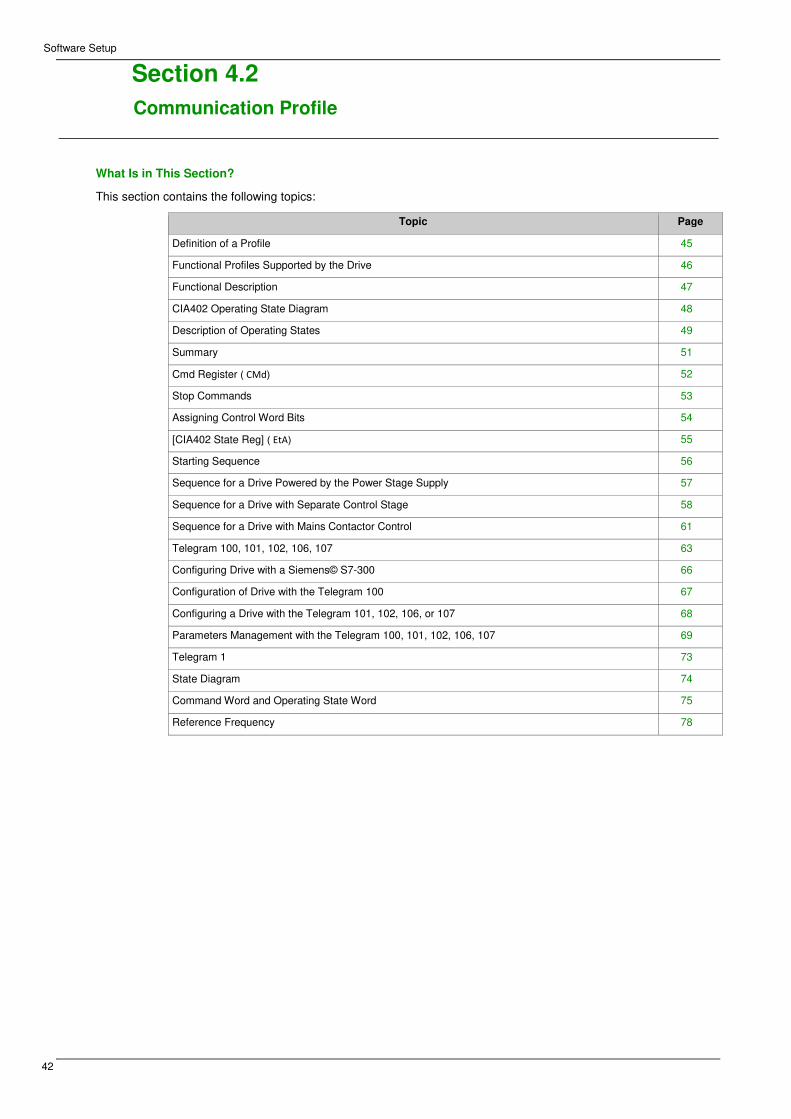
Operating State Description
6 - Quick stop active The drive performs a fast stop and remains locked in the operating state 6-Quick
stop active. Before restarting the motor, it is required to go to the operating state
2-switch on disabled. During fast stop, the drive is unlocked and power is supplied to the motor. The configuration parameters cannot be modified. The condition for transition 12 to state 2 - Switch on disabled depends on
the value of the parameter Quick stop mode (QStd): If the Quick stop mode parameter has the value FST2, the drive stops
according to the fast stop ramp and then changes to state 2 - Switch on
disabled . If the Quick stop mode parameter has the value FST6, the drive
stops according to the fast stop ramp and then remains in state 6 - Quick stop
active until:
� A Disable voltage command is received or � The STOP key is pressed or � A freewheel stop
command via the digital input of the terminal.
7 - Fault reaction
active Transient state during which the drive performs an action corresponding to the
selected error response.
8 - Fault Error response terminated. Power stage is disabled. The drive is locked, no power is supplied to the motor.
Software Setup
49
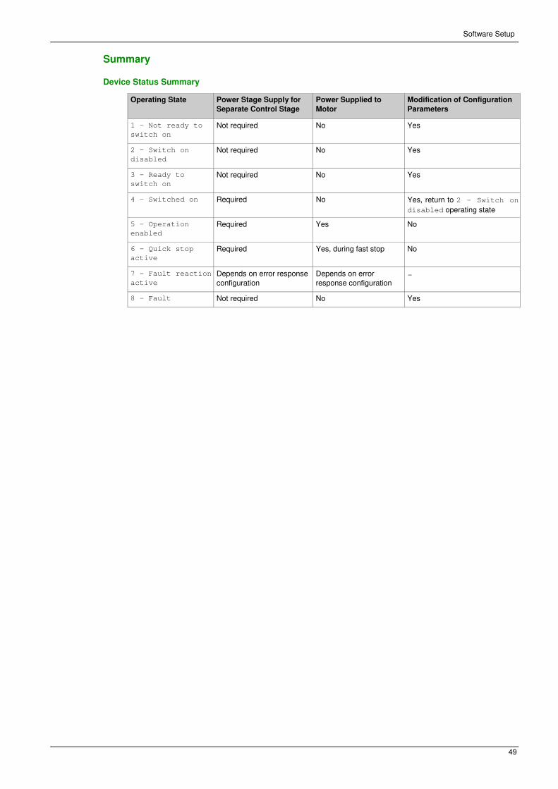
Summary
Device Status Summary
Operating State Power Stage Supply for
Separate Control Stage Power Supplied to
Motor Modification of Configuration
Parameters
1 - Not ready to
switch on Not required No Yes
2 - Switch on
disabled Not required No Yes
3 - Ready to
switch on Not required No Yes
4 - Switched on Required No Yes, return to 2 - Switch on
disabled operating state
5 - Operation
enabled Required Yes No
6 - Quick stop
active Required Yes, during fast stop No
7 - Fault reaction
active Depends on error response
configuration Depends on error
response configuration −
8 - Fault Not required No Yes

Software Setup
50
Cmd Register (CMd)
Bit Mapping of the Control Word
Bit 7 Bit 6 Bit 5 Bit 4 Bit 3 Bit 2 Bit 1 Bit 0
Fault reset Reserved
(=0) Reserved
(=0) Reserved
(=0) Enable
operation Quick stop Enable
voltage Switch on
0 to 1
transition =
Error is
reset (after
cause of
error is no
longer
active)
1 = Run command
0 = Quick
stop active Authorization to supply AC
power
Mains
contactor
control
Bit 15 Bit 14 Bit 13 Bit 12 Bit 11 Bit 10 Bit 9 Bit 8
Manufacturer
specific
assignable
Manufacturer
specific
assignable
Manufacturer
specific
assignable
Manufacturer
specific
assignable
Manufacturer
specific Reserved
(=0) Reserved
(=0) Halt
0 = Forward direction
asked 1=
Reverse
direction
asked
Halt
Command State
Transition
Final
Operating
State
Bit 4 Bit 3 Bit 2 Bit 1 Bit 0 Example
Value Fault
Reset Enable
Operation Quick
Stop Enable
Voltage Switch
On
Shutdown 2, 6, 8 3 - Ready
to switch
on
X X 1 1 0 0006 hex
Switch on 3 4 -
Switched
on
X X 1 1 1 0007 hex
Enable
operation 4 5 -
Operation
enabled
X 1 1 1 1 000F hex
Disable
operation 5 4 -
Switched
on
X 0 1 1 1 0007 hex
Disable
voltage 7, 9, 10, 12 2 - Switch
on
disabled
X X X 0 X 0000 hex
Quick stop 11 6 - Quick
stop
active
X X 0 1 X 0002 hex
7, 10 2 - Switch
on
disabled
Fault
reset 15 2 - Switch
on
disabled
0 → 1 X X X X 0080 hex
X: Value is of no significance for this command.
0[gs56] 1: Command on rising edge.

Software Setup
51
Stop Commands
Halt Command
The Halt command enables movement to be interrupted without having to leave the 5 - Operation
enabled state. The stop is performed in accordance with the [Type of stop] ( Stt) parameter.
If the Halt command is active, no power is supplied to the motor and no torque is applied.
Regardless of the assignment of the [Type of stop] ( Stt) parameter [Fast stop Assign] ( FSt) , [Ramp
stop] ( rMP) , [Freewheel Stop] ( nSt) , or [DC Injection Assign] ( dCI) , the drive remains in the 5 -
Operation enabled state.
Fast Stop Command
A Fast Stop command at the terminals or using a bit of the control word assigned to Fast Stop
causes a change to the 4 - Switched on
Freewheel Command
A Freewheel Stop command using a digital input of the terminal or a bit of the control word assigned
to Freewheel Stop causes a change to operating state 2 - Switch on disabled.

Software Setup
52
Assigning Control Word Bits
Function Codes
In the CiA402 profile, fixed assignment of a function input is possible using the following codes:
Bit Fieldbus Module
Bit 11 C311
Bit 12 C312
Bit 13 C313
Bit 14 C314
Bit 15 C315
For example, to assign the DC injection braking to bit13 of the fieldbus module, simply configure the [DC
Injection Assign] ( dCI) parameter with the [C313] ( C313) value.
Bit 11 is assigned by default to the operating direction command [Reverse Assign] ( rrS .)

Software Setup
53
[CIA402 State Reg] (EtA)
Bit Mapping of the Status Word
Bit 7 Bit 6 Bit 5 Bit 4 Bit 3 Bit 2 Bit 1 Bit 0
Warning Switch on
disabled Quick stop Voltage
enabled Fault Operation
enabled Switched on Ready to
switch on
A warning is
active Power stage
supply disabled 0 = Quick
stop is active Power stage
supply
present
Error
detected Running Ready 1 =
Awaiting
power
Stage
supply
Bit 15 Bit 14 Bit 13 Bit 12 Bit 11 Bit 10 Bit 9 Bit 8
Manufacturer -specific
Direction of
rotation
Manufacturerspecific
Stop via STOP key Reserved
(=0) Reserved
(=0) Internal limit
active Target
reached Remote Reserved
(=0)
Reference
value outside
limits
Reference
value
reached
Command or
reference
value via
fieldbus
Operating
State Bit 6 Bit 5 Bit 4 Bit 3 Bit 2 Bit 1 Bit 0 ETA
Masked by
006F H (1) Switch On
Disabled Quick
Stop Voltage
Enabled Fault Operation
Enabled Switched
On
Ready to
Switch
On
1 -Not
ready to
switch on
0 X X 0 0 0 0 −
2 -Switch
on
disabled
1 X X 0 0 0 0 0040 hex
3 -Ready
to switch
on
0 1 X 0 0 0 1 0021 hex
4
Switched
on
0 1 1 0 0 1 1 0023 hex
5
Operation
enabled
0 1 11 0 1 1 1 0027 hex
6 -Quick
stop
active
0 0
0 1 1 1 0007 hex
7 -Fault
reaction
active
0 X X 1 1 1 1 −
8 -Fault 0 X X 1 0 0 0 0008
hex(2)..
.0028 hex (1) This mask can be used by the PLC program to test the diagram state.
(2) detected error following operating state 6 - Quick stop active.
X: In this state, the value of the bit can be 0 or 1.
Software Setup
54
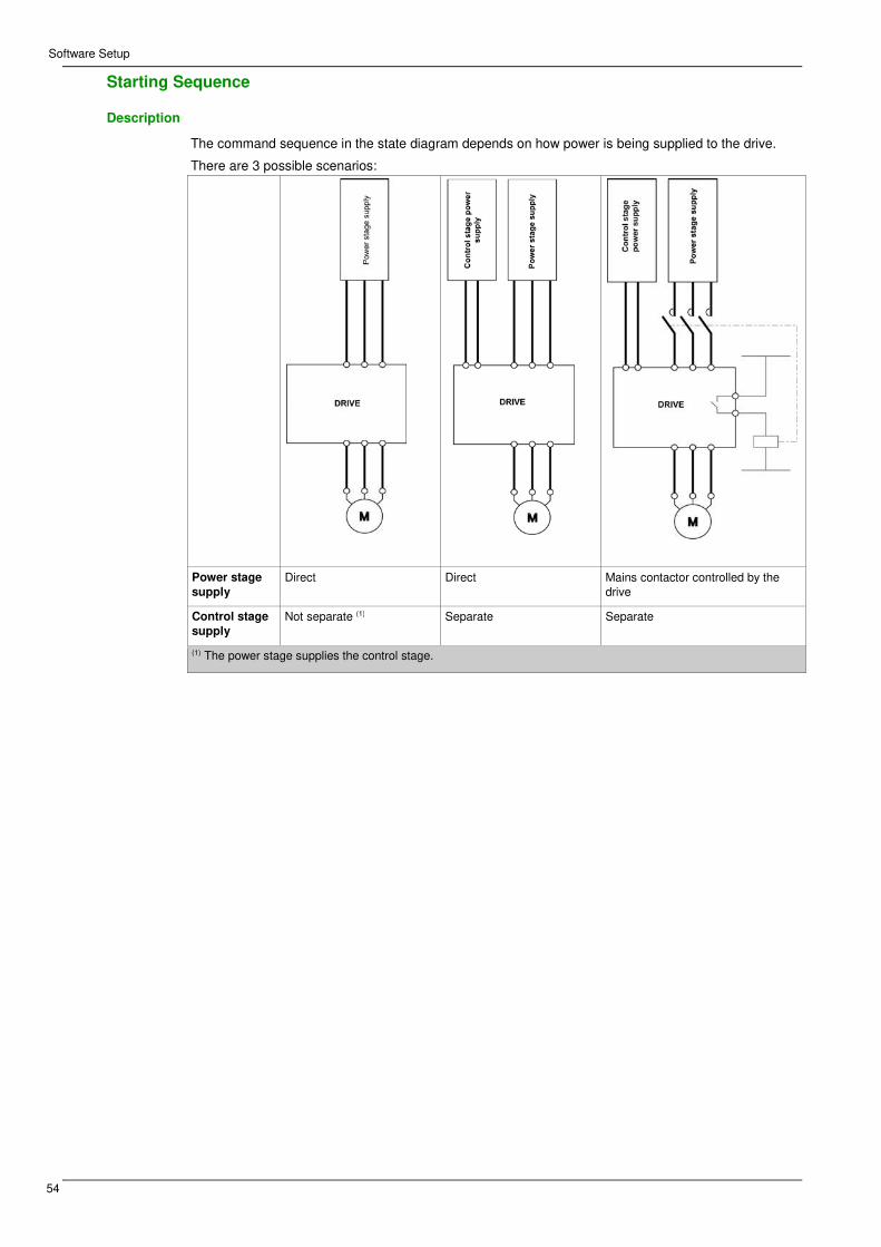
Starting Sequence
Description
The command sequence in the state diagram depends on how power is being supplied to the drive.
There are 3 possible scenarios:
Power stage
supply Direct Direct Mains contactor controlled by the
drive
Control stage
supply Not separate (1) Separate Separate
(1) The power stage supplies the control stage.

Software Setup
55
Sequence for a Drive Powered by the Power Stage Supply
Description
Both the power and control stages are powered by the power stage supply.
If power is supplied to the control stage, it has to be supplied to the power stage as well.
The following sequence must be applied:
Step 1
Apply the 2 - Shut down command
Step 2
� Check that the drive is in the operating state 3 - Ready to switch on.
� Then apply the 4 - Enable operation command. � The motor can
be controlled (send a reference value not equal to zero).
NOTE: It is possible, but not necessary to apply the 3 - Switch on command followed by the 4 -
Enable Operation command to switch successively into the operating states 3 - Ready to Switch
on, 4 - Switched on and then 5 - Operation Enabled. The 4 - Enable operation
command is sufficient.
Software Setup
56
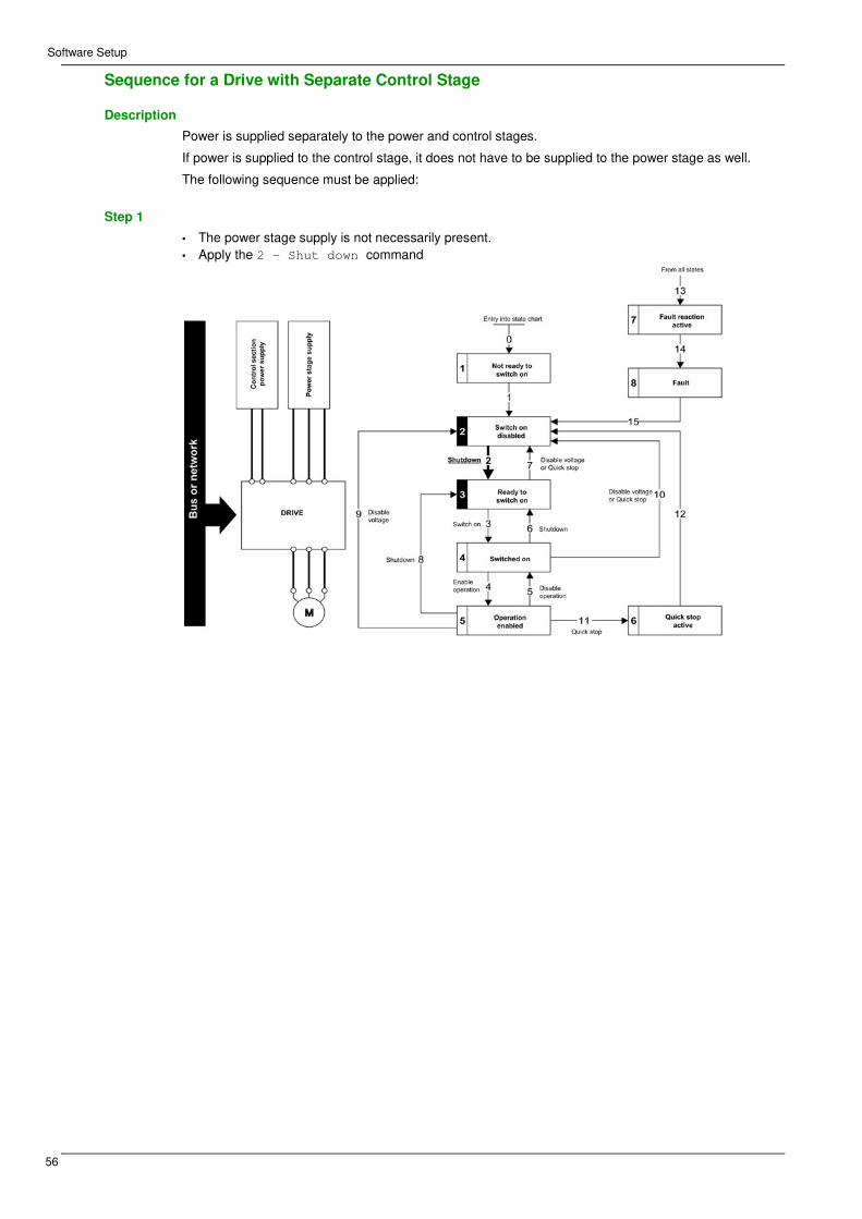
Sequence for a Drive with Separate Control Stage
Description
Power is supplied separately to the power and control stages.
If power is supplied to the control stage, it does not have to be supplied to the power stage as well.
The following sequence must be applied:
Step 1
• The power stage supply is not necessarily present.
• Apply the 2 - Shut down command

Software Setup
57
Step 2
• Check that the drive is in the operating state 3 - Ready to switch on.
• Check that the power stage supply is present (Voltage enabled of the status word).
• Apply the 3 - Switch on command
Power Stage Supply Terminal Display Status Word
Absent nLP 21 hex
Present rdY 31 hex

Software Setup
58
Step 3
� Check that the drive is in the operating state 4 - Switched on. � Then apply the 4 - Enable
operation command. � The motor can be controlled (send a reference value not equal to zero). � If
the power stage supply is still not present in the operating state 4 - Switched on after a time delay
[Mains V. time out] ( LCt) , the drive triggers an error [Input Contactor] ( LCF) .

Software Setup
59
Sequence for a Drive with Mains Contactor Control
Description
Power is supplied separately to the power and control stages.
If power is supplied to the control stage, it does not have to be supplied to the power stage as well. The
drive controls the mains contactor.
The following sequence must be applied:
Step 1 � The power stage supply is not present as the mains contactor is not being controlled. � Apply the
2 - Shutdown command.

Software Setup
60
Step 2
� Check that the drive is in the operating state 3 - Ready to switch on.
� Apply the 3 - Switch on command, which closes the mains contactor and switch on the power
stage supply.

Software Setup
61
Telegram 100, 101, 102, 106, 107
Overview
The following diagram shows the native modes for telegram 100:
The native mode of the PROFIBUS DP is used when telegram 100 is used.
The PKW area of telegram 100, which is used for a simple parameter management, is compliant with the
PKW mechanism used with the PROFIBUS DP fieldbus module of the ER51, ER40, ER24.
NOTE: After switching from one telegram to another, the drive shall be restarted to validate the new
configuration.
The following diagram shows the native modes for telegram 101, 106, 107:

Software Setup
62
The following diagram shows the native modes for telegram 102:
Periodic Exchanges
The following table provides the details of telegram 100, 101, and 102
Telegram 100 Telegram 101 Telegram 102
PLC>VSD VSD>PLC PLC>VSD VSD>PLC PLC>VSD VSD>PLC
PKW 1 PKE PKE PKE PKE −
PKW 2 R/W R/W R/W R/W
PKW 3 PWE PWE PWE PWE
PKW 4 PWE PWE PWE PWE
Cyclic data 1 OCA1
address of
CMD =8501*
OMA1 address
of ETA =3201* OCA1
address of
CMD =8501*
OMA1 address
of ETA =3201* OCA1
address of
CMD =8501*
OMA1 address
of ETA =3201*
Cyclic data 2 OCA2
address of
LFRD =8602*
OMA2
address of
RFRD =8604*
OCA2
address of
LFRD =8602*
OMA2
address of
RFRD =8604*
OCA2
address of
LFRD =8602*
OMA2
address of
RFRD =8604*
Cyclic data 3
OCA3 default
=0 OMA3 default
=0 OCA3 default
=0 OMA3 default
=0
Cyclic data 4 OCA4 default
=0 OMA4 default
=0 OCA4 default
=0 OMA4 default
=0
Cyclic data 5 OCA5 default
=0 OMA5 default
=0 OCA5 default
=0 OMA5 default
=0
Cyclic data 6 OCA6 default
=0 OMA6 default
=0 OCA6 default
=0 OMA6 default
=0
*:default Modbus address.

Software Setup
63
The following table provides the details of telegram 106 and 107
Telegram 106 Telegram 107
PLC>VSD VSD>PLC PLC>VSD VSD>PLC
PKW 1 PKE PKE PKE PKE
PKW 2 R/W R/W R/W R/W
PKW 3 PWE PWE PWE PWE
PKW 4 PWE PWE PWE PWE
Cyclic data 1 OCA1 address of
CMD =8501* OMA1 address of
ETA =3201* OCA1 address of
CMD =8501* OMA1 address of
ETA =3201*
Cyclic data 2 OCA2 address of
LFRD =8602* OMA2 address of
RFRD =8604* OCA2 address of
LFRD =8602* OMA2 address of
RFRD =8604*
Cyclic data 3 OCA3 default =0 OMA3 default =0 OCA3 default =0 OMA3 default =0
Cyclic data 4 OCA4 default =0 OMA4 default =0 OCA4 default =0 OMA4 default =0
Cyclic data 5 OCA5 default =0 OMA5 default =0 OCA5 default =0 OMA5 default =0
Cyclic data 6 OCA6 default =0 OMA6 default =0 OCA6 default =0 OMA6 default =0
Cyclic data 7 OCA7 default =0 OMA7 default =0 OCA7 default =0 OCA7 default =0
Cyclic data 8 OCA8 default =0 OMA8 default =0 OCA8 default =0 OCA8 default =0
Cyclic data 9
OCA9 default =0 OCA9 default =0
Cyclic data 10 OCA10 default =0 OCA10 default =0
Cyclic data 11 OCA11 default =0 OCA11 default =0
Cyclic data 12 OCA12 default =0 OCA12 default =0
Cyclic data 13 OCA13 default =0 OCA13 default =0
Cyclic data 14 OCA14 default =0 OCA14 default =0
Cyclic data 15 OCA15 default =0 OCA15 default =0
Cyclic data 16 OCA16 default =0 OCA16 default =0
*:default Modbus address.
The configuration of the cyclic data is made with the PROFIBUS DP master configuration tool. The Modbus
address of the parameter linked to each cyclic data must be defined as in the following example with the HW
configuration software:
Input cyclic data 1/2 and output cyclic data 1/2 are already preconfigured to (CMd) (8501) and (LFrd) (8602);
(EtA) (3201) and (rFrd) (8604).
If a null address Modbus is entered, no link between the related cyclic data and the drive is established. In any
case, the 6 cyclic data are not disabled and the 6 cyclic data takes place in the I/O memory image of the
controller.
1 Modbus address is entered in this field 2 Data type is entered in this field

Software Setup
64
Configuring Drive with a Siemens© S7-300
GSD Installation
First download, and install the GSD file of the drive in the hardware configuration tool of the SIMATIC
STEP7® software.
You can find the GSD file and its associated picture on www.schneider-electric.com.
From the menu > Options > Install GSD File...
Once installed you can see the drive, in the library, as follow:

Software Setup
65
Configuration of Drive with the Telegram 100
Description
With this telegram, the drive is controlled with two process data.
Configure master PLC and its PROFIBUS DP network. Then select and place the drive from the library
to the bus:
Define the addresses of the cyclic data and PKW data in the PLC periphery:
By default, the process data are linked to (CMd), (LFrd), (EtA) and (rFrd) (native CiA 402 profile of the
drive).
You can check that the exchanges are working properly with the Monitor/Modify function of the
configuration tool:

Software Setup
66
Configuring a Drive with the Telegram 101, 102, 106, or 107
Configuring the Drive Communication Scanner
The configuration of the fieldbus module is defined by the master, by default the 2 first read and write
are linked to the default parameters: (CMd), (LFrd), (EtA) and (rFrd). The 4 next read or write parameters
are not configured.
To add new parameters or modify the default configuration of the communication scanner, open the
properties dialog box of the slave device and configure the OCA/OMA values in the parameter
assignment tab.
1 Internal Modbus address 2 Data type is entered in this field
New parameters are added or modified by entering the drive Modbus address.
For example: (OMA3) is configured to read the value of (ACC), which Modbus address is 9001.

Software Setup
67
Parameters Management with the Telegram 100, 101, 102, 106, 107
Description
In native modes several accesses to the drive parameters are possible: � The standard acyclic
requests from PROFIdrive, for more information see PROFIdrive Parameters Channel (see page
22).
� PKW mechanisms – consistent with Altivar 32,61, and 71 for 16-bit data.
Parameter Management Through the PKW Area
With telegram 100, 101, 106, 107 you can read or write any drive parameter by using this PKW area.
(This addressing format is identical to the PKW mechanism of the Altivar 32,61, and 71).
NOTE: The management of the parameters (compatibility with series 1 product) is BLEMO specific.
Actually, previous versions of PROFIdrive also specified parameter management thought PKW, are not
compatible with BLEMO method. In recent versions, parameters are managed with acyclic messages,
and the PNO PKW method is obsolete.
The PKW area is made of four input words and four output words.
The table lists the controller-to-drive parameters in the input PKW area:
PKW Number PKE Name Description
PKW1 PKE The Modbus address of the parameter is detailed here.
PKW2 R/W Request code: 0: no request 1: read 2: write (16 bit) 3: write (32 bit)
PKW3 PWE Parameter is used when PKW2 = 3
PKW4 PWE Parameter value in case of write request
The table lists the drive-to-controller parameters in the output PKW area:
PKW Number PKE Name Description
PKW1 PKE Copy of the input PKE
PKW2 R/W Response code: 0: no request 1: read done (16 bit) 2: write done (16 bit) 3: request in progress 4: read done (32 bit) 5: write done (32 bit) 7: read or write error
PKW3 PWE Parameter is used when PKW2 = 4 or 5
PKW4 PWE If the request is successful, the parameter value is copied here.

Software Setup
68
DP V1 / Acyclic Messaging - BLEMO Specific
The PROFIBUS DPV1 telegram includes a header, described in the following diagram:
The following table lists the content of the DPV1 header:
DU Byte - nr
Function code 0
Slot_num 1
Index 2
Length 3
Data 4 - 5
An indirection mechanism is used: � Step 1:
DU Bytes Request Positive answer Negative answer
Function code 0 5E hex (read) 5F hex (write)
5E hex (read) 5F hex (write)
DF hex (read)
DE hex (write)
Slot_num 1 1 1 80 hex
Index 2 E9 hex E9 hex XX hex (error type)
Length 3 2 − YY hex (error type)
Data 4 - 5 ZZZZ hex (ZZZZ is
the Modbus address − 0
� Step 2:
DU Bytes Request Positive answer Negative answer
Function code 0 5E hex (read) 5F hex (write)
5E hex (read) 5F hex (write)
DF hex (read)
DE hex (write)
Slot_num 1 1 1 80 hex
Index 2 EA hex E9 hex XX hex (error type)
Length 3 2 − YY hex (error type)
Data 4 - 5 Read: - Write: 0010 hex
− 0
Software Setup
69
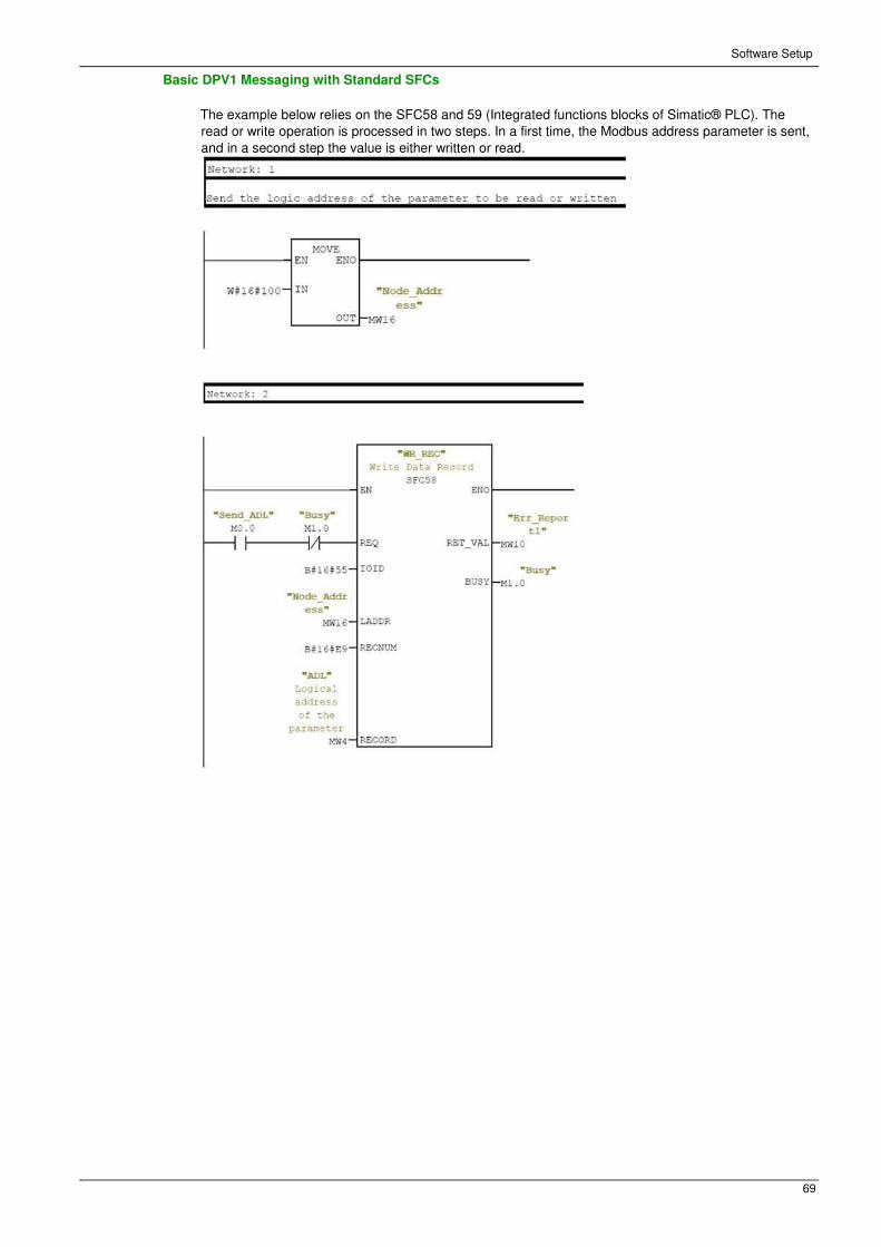
Basic DPV1 Messaging with Standard SFCs
The example below relies on the SFC58 and 59 (Integrated functions blocks of Simatic® PLC). The
read or write operation is processed in two steps. In a first time, the Modbus address parameter is sent,
and in a second step the value is either written or read.

Software Setup
70
Software Setup
71
Telegram 1
Overview
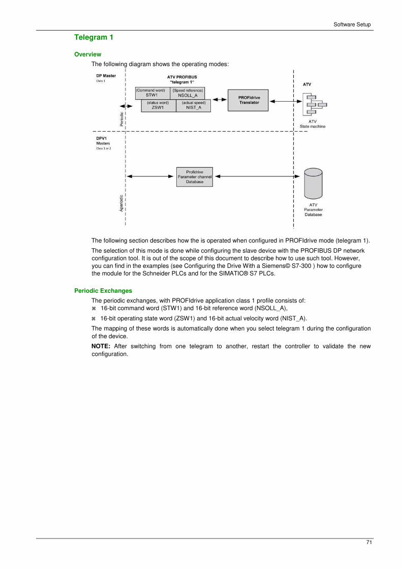
The following diagram shows the operating modes:
The following section describes how the is operated when configured in PROFIdrive mode (telegram 1).
The selection of this mode is done while configuring the slave device with the PROFIBUS DP network
configuration tool. It is out of the scope of this document to describe how to use such tool. However,
you can find in the examples (see Configuring the Drive With a Siemens© S7-300 ) how to configure
the module for the Schneider PLCs and for the SIMATIC® S7 PLCs.
Periodic Exchanges
The periodic exchanges, with PROFIdrive application class 1 profile consists of:
� 16-bit command word (STW1) and 16-bit reference word (NSOLL_A),
� 16-bit operating state word (ZSW1) and 16-bit actual velocity word (NIST_A).
The mapping of these words is automatically done when you select telegram 1 during the configuration
of the device.
NOTE: After switching from one telegram to another, restart the controller to validate the new
configuration.

Software Setup
72
State Diagram
Description
The following state diagram shows the PROFIdrive state machine for the application class 1. The diagram
also describes the command word and operating state word.

Software Setup
73
Command Word and Operating State Word
Overview
The table lists the command wording from PROFIdrive application profile class 1:
STW1
Bit 7 Bit 6 Bit 5 Bit 4 Bit 3 Bit 2 Bit 1 Bit 0
Fault reset − − − Enable
operation Quick stop Coast stop ON/OFF
Bit 15 Bit 14 Bit 13 Bit 12 Bit 11 Bit 10 Bit 9 Bit 8
− − − − − Control and reference by PLC
− −
The table lists the status from PROFIdrive application profile class 1:
ZSW1
Bit 7 Bit 6 Bit 5 Bit 4 Bit 3 Bit 2 Bit 1 Bit 0
Warning Switching
inhibited Quick stop
not activated Coast stop
not
activated
Error
detected Operation
enabled Ready to
operate Ready to
switch ON
Bit 15 Bit 14 Bit 13 Bit 12 Bit 11 Bit 10 Bit 9 Bit 8
− Reserved Reserved Reserved Reserved F or n
reached or
exceeded
Control
requested Speed error
found within tolerance
range
Software Setup
74
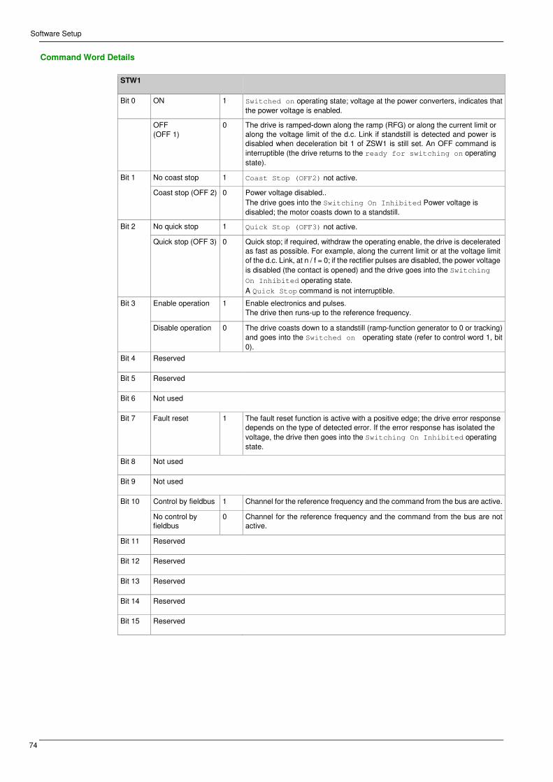
Command Word Details
STW1
Bit 0 ON 1 Switched on operating state; voltage at the power converters, indicates that
the power voltage is enabled.
OFF (OFF 1)
0 The drive is ramped-down along the ramp (RFG) or along the current limit or
along the voltage limit of the d.c. Link if standstill is detected and power is
disabled when deceleration bit 1 of ZSW1 is still set. An OFF command is
interruptible (the drive returns to the ready for switching on operating
state).
Bit 1 No coast stop 1 Coast Stop (OFF2) not active.
Coast stop (OFF 2) 0 Power voltage disabled.. The drive goes into the Switching On Inhibited Power voltage is
disabled; the motor coasts down to a standstill.
Bit 2 No quick stop 1 Quick Stop (OFF3) not active.
Quick stop (OFF 3) 0 Quick stop; if required, withdraw the operating enable, the drive is decelerated
as fast as possible. For example, along the current limit or at the voltage limit
of the d.c. Link, at n / f = 0; if the rectifier pulses are disabled, the power voltage is disabled (the contact is opened) and the drive goes into the Switching
On Inhibited operating state.
A Quick Stop command is not interruptible.
Bit 3 Enable operation 1 Enable electronics and pulses. The drive then runs-up to the reference frequency.
Disable operation 0 The drive coasts down to a standstill (ramp-function generator to 0 or tracking)
and goes into the Switched on operating state (refer to control word 1, bit
0).
Bit 4 Reserved
Bit 5 Reserved
Bit 6 Not used
Bit 7 Fault reset 1 The fault reset function is active with a positive edge; the drive error response
depends on the type of detected error. If the error response has isolated the
voltage, the drive then goes into the Switching On Inhibited operating
state.
Bit 8 Not used
Bit 9 Not used
Bit 10 Control by fieldbus 1 Channel for the reference frequency and the command from the bus are active.
No control by
fieldbus 0 Channel for the reference frequency and the command from the bus are not
active.
Bit 11 Reserved
Bit 12 Reserved
Bit 13 Reserved
Bit 14 Reserved
Bit 15 Reserved
Software Setup
75
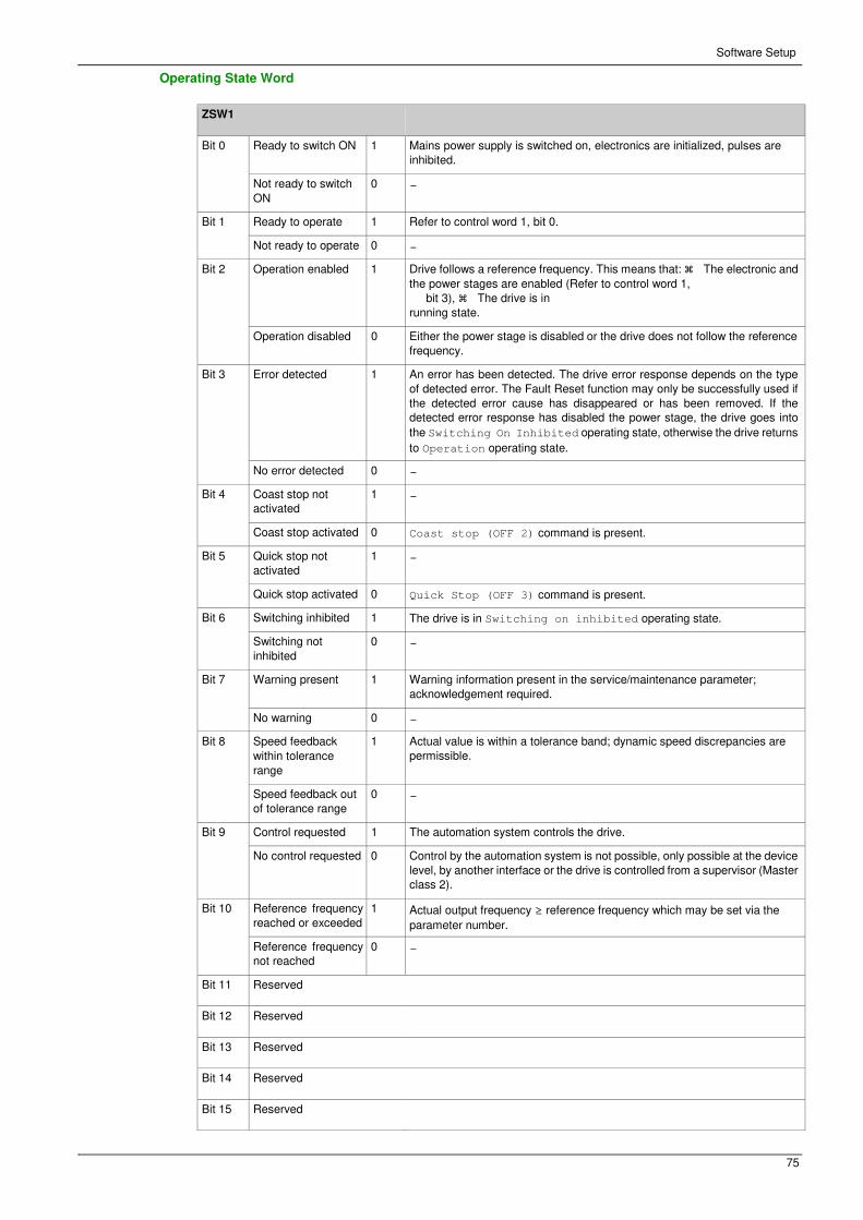
Operating State Word
ZSW1
Bit 0 Ready to switch ON 1 Mains power supply is switched on, electronics are initialized, pulses are
inhibited.
Not ready to switch ON
0 −
Bit 1 Ready to operate 1 Refer to control word 1, bit 0.
Not ready to operate 0 −
Bit 2 Operation enabled 1 Drive follows a reference frequency. This means that: � The electronic and
the power stages are enabled (Refer to control word 1, bit 3), � The drive is in
running state.
Operation disabled 0 Either the power stage is disabled or the drive does not follow the reference
frequency.
Bit 3 Error detected 1 An error has been detected. The drive error response depends on the type
of detected error. The Fault Reset function may only be successfully used if
the detected error cause has disappeared or has been removed. If the
detected error response has disabled the power stage, the drive goes into
the Switching On Inhibited operating state, otherwise the drive returns
to Operation operating state.
No error detected 0 −
Bit 4 Coast stop not
activated 1 −
Coast stop activated 0 Coast stop (OFF 2) command is present.
Bit 5 Quick stop not
activated 1 −
Quick stop activated 0 Quick Stop (OFF 3) command is present.
Bit 6 Switching inhibited 1 The drive is in Switching on inhibited operating state.
Switching not
inhibited 0 −
Bit 7 Warning present 1 Warning information present in the service/maintenance parameter;
acknowledgement required.
No warning 0 −
Bit 8 Speed feedback within tolerance
range
1 Actual value is within a tolerance band; dynamic speed discrepancies are
permissible.
Speed feedback out
of tolerance range 0 −
Bit 9 Control requested 1 The automation system controls the drive.
No control requested 0 Control by the automation system is not possible, only possible at the device
level, by another interface or the drive is controlled from a supervisor (Master
class 2).
Bit 10 Reference frequency
reached or exceeded 1 Actual output frequency ≥ reference frequency which may be set via the
parameter number.
Reference frequency
not reached 0 −
Bit 11 Reserved
Bit 12 Reserved
Bit 13 Reserved
Bit 14 Reserved
Bit 15 Reserved

Software Setup
76
Reference Frequency
Channel for Reference Frequency
The reference frequency, written in NSOLL_A is defined by the following formula:
Reference frequency in Hz = (NSOLL_A x [Max Frequency] (tFr)) /4000 HEX
Reference Frequency Range
The table lists the different values for the reference frequency and the correspondence for the drive:
Value Reference Frequency Used by the Drive
0x0000 0
0x4000 100% of [Max Frequency] (tFr)
0xC000 –100% of [Max Frequency] (tFr)
PROFIdrive / Acyclic Messaging
For more information, see PROFIdrive Parameters Channel (see page 22).

Software Setup
77
FielatSection 4.3
Fieldbus Integration Tutorial
Fieldbus Integration Tutorial
Simple LAD Language FC (Controlling the Drive in CiA 402 Mode)
The following example shows a simple LAD language FC for controlling the drive in CiA402 mode

Software Setup
78

Software Setup
79
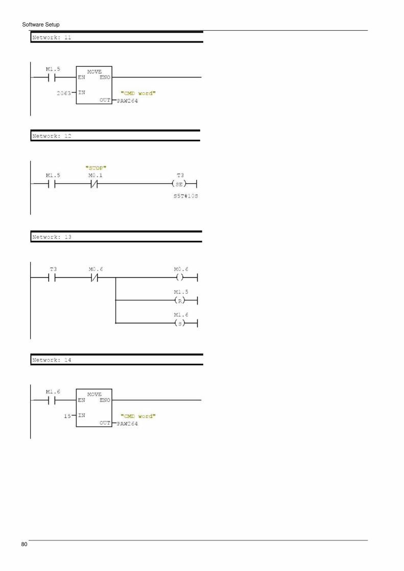
Software Setup
80

NHA80941 08/2015 81
Altivar Process 900 Operation
Chapter 5Operation
Operation
What Is in This Chapter?
This chapter contains the following sections:
Section Topic Page
5.1 Operating States 84
5.2 Operating Modes 85

Operation
82
Section 5.1
Operating States
Configuring Communication Error Response
Description
The response of the drive in the event of communication interruption can be configured. Configuration
can be performed using the display terminal from the [Complete settings] (CSt-), [Error/Warning
handling] (CSWM-) menu, [Embedded modbus TCP] ( EMtC-) submenu, via the [Eth Error Response]
( EtHL) parameter.
The values of the [Eth Error Response] ( EtHL) parameter, which triggers a transition to the operating
state fault are:
Value Meaning
[Freewheel Stop] (YES) Freewheel stop (factory setting)
[Ramp stop] (rMP) Stop on ramp
[Fast stop] ( FSt) Fast stop
[DC injection] ( dCI) DC injection stop
The values of the () parameter, which does not trigger a transition to the operating state fault are:
Value Meaning
[Ignore] (nO) Detected error ignored
[Per STT] (Stt) Stop according to configuration of [Type of stop] (Stt)
[Fallback Speed] (LFF) Change to fallback speed, maintained as long as the detected error persists
and the run command has not been removed
[Speed maintained] (rLS) The drive maintains the speed at the time the detected error occurred, as
long as the detected error persists, and the run command has not been
removed
The fallback speed can be configured in the [Complete settings] (CSt-), [Error/Warning handling]
(CSWM-) menu, [Fallback speed] ( LFF-) submenu, using the [FallbackSpeed] (LFF) parameter.
WARNING
LOSS OF CONTROL
If this parameter is set to nO, fieldbus communication monitoring is disabled.
� Only use this setting after a thorough risk assessment in compliance with all regulations and
standards that apply to the device and to the application.
� Only use this setting for tests during commissioning.
� Verify that communication monitoring has been re-enabled before completing the commissioning
procedure and performing the final commissioning test.
Failure to follow these instructions can result in death, serious injury, or equipment damage. Operating Modes

Operation
83
Section 5.2
Operating Modes
What Is in This Section?
This section contains the following topics:
Topic Page
Configuring the Control Channel 86
Configuration of the Drive for Operation in I/O Profile 87
Configuration of the Drive for Operation with CiA 402 Profile in Combined Mode 88
Configuration of the Drive for Operation with CiA 402 Profile in Separate Mode 89

Operation
84
Configuring the Control Channel
Overview
This chapter explains how to configure the drive for operation from the communication network through
three following examples. � I/O mode - a simple command word (based on forward, reverse, and reset
binary commands). � Combined mode (with native profile CiA 402) - Both reference value and command
word come from the communication network. � Separate (with native profile CiA 402) - reference value
and command word come from separate sources: for example, the command word (in CiA 402) comes
from the communication network and the reference value from the HMI.

Operation
85
Configuration of the Drive for Operation in I/O Profile
Description
For the I/O profile, here is a simple example, which can be extended with additional features. The
command word is made of run forward (bit 0 of CMd), run reverse (bit 1 of CMd), and the function fault
reset (bit 7 of CMd).
The settings are the following:
[Ref Freq 1 Config] (Fr1) [HMI] (HMI)
[Control Mode] (CHCF) [I/O profile] IO
[Command switching] (CCS) Default
[Cmd channel 1] (Cd1) [Com. Module] (nEt)
The bits of the command word can now be configured.
In the [Command and Reference] ( CrP-) menu configure:
[Reverse Assign] (rrS) [CD01] (Cd01)
In the [Error/Warning handling] ( CSWM-) menu, [Fault reset] ( rSt-) submenu, configure:
[Fault Reset Assign] (rSF) [CD07] (Cd07)
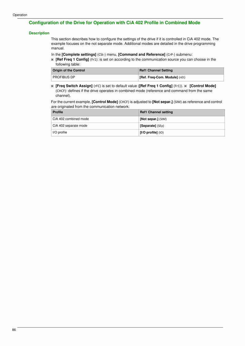
Operation
86
Configuration of the Drive for Operation with CiA 402 Profile in Combined Mode
Description
This section describes how to configure the settings of the drive if it is controlled in CiA 402 mode. The
example focuses on the not separate mode. Additional modes are detailed in the drive programming
manual.
In the [Complete settings] (CSt-) menu, [Command and Reference] (CrP-) submenu:
� [Ref Freq 1 Config] (Fr1): is set on according to the communication source you can choose in the
following table:
Origin of the Control Ref1 Channel Setting
PROFIBUS DP [Ref. Freq-Com. Module] (nEt)
� [Freq Switch Assign] (rFC) is set to default value ([Ref Freq 1 Config] (Fr1)). � [Control Mode]
(CHCF): defines if the drive operates in combined mode (reference and command from the same
channel).
For the current example, [Control Mode] (CHCF) is adjusted to [Not separ.] (SIM) as reference and control
are originated from the communication network:
Profile Ref1 Channel setting
CiA 402 combined mode [Not separ.] (SIM)
CiA 402 separate mode [Separate] (SEp)
I/O profile [I/O profile] (IO)

Operation
87
Configuration of the Drive for Operation with CiA 402 Profile in Separate Mode
Description
Alternate combinations are possible, see the drive programming manual for the list of possible settings.
For example:
The drive is controlled from the fieldbus (PROFIBUS DP) but the reference value is adjusted on the
controller terminal. The control word comes from the controller and is written according to CiA 402 profile.
The settings are as shown in the table:
[Ref Freq 1 Config] (Fr1) [AI1] (AI1)
[Control Mode] (CHCF) [Separate] (SEp)
[Cmd channel 1] (Cd1) [Com. Module] (nEt)
[Freq Switch Assign] (rFC) Factory setting

Operation
88

89
A900 ing
Chapter 6Diagnostic and Troubleshooting
Diagnostic and Troubleshooting
What Is in This Chapter?
This chapter contains the following topics:
Topic Page
Fieldbus Status LEDs 92
Connection for Fieldbus Mode 93
Fieldbus Function Test 94
Communication Interruption 95
Monitoring of Communication Channel 97
Control-Signal Diagnostics 99

Diagnostic and Troubleshooting
90
Fieldbus Status LEDs
LED Indicators
The following figure describes the LEDs status module:
LED Description
Item LED Description
1 RUN Module status
2 BF Network Error status
Module Status
This LED indicates the module status:
Color & Status Description
OFF The device is powered off
Green ON Fieldbus communication active
Network Error Status
Color & Status Description
OFF The device does not have a slave address or is powered off
Red ON Fieldbus error is detected
Red flashing Incorrect configuration

Diagnostic and Troubleshooting
91
Connection for Fieldbus Mode
Description
If the product cannot be addressed via the fieldbus, first check the connections. The product manual
contains the technical data of the device and information on network and device installation. Check the
following:
� Power connections to the device
� Fieldbus cable and fieldbus wiring
� Network connection to the device
Diagnostic and Troubleshooting
92
Fieldbus Function Test
Description
If the connections are correct, check the settings for the fieldbus addresses. After correct configuration of
the transmission data, test the fieldbus mode.
In addition to the controller that knows the device via the data in the GSD file and its address, a bus
monitor should be installed. As a passive device, it can display messages. � Switch off or on the supply
voltage of the drive system. � Observe the network messages shortly after switching on the drive system.
A bus monitor can be used to record the elapsed time between telegrams and the relevant information in
the telegram.
Possible Errors: Addressing, Parameterization, Configuration
If it is impossible to connect to a device, check the following:
� Addressing: The address of the network device must be between 2 to 126. Each network device must
have a unique address.
� Parameterization: The parameterized ident number and the user parameters must match the values
stored in the GSD file. � Configuration: The data length in input and output direction must be
identical to the length specified in the GSD file.

Diagnostic and Troubleshooting
93
Communication Interruption
Description
The drive triggers an error [Internal Link Error] (ILF) when the following events occur:
� Hardware error is detected on the PROFIBUS DP module
� Communication interruption between the PROFIBUS DP module and the drive
The response of the drive in the event of an [Internal Link Error] (ILF) error cannot be configured, and
the drive stops in freewheel. This detected error requires a power reset.
The diagnostic parameter can be used to obtain more detailed information about the origin of the [Internal
Link Error] (ILF) ([InterCom Error1] (ILF1) if the detected error has occurred on fieldbus module in slot
A).
The [InterCom Error1] (ILF1) parameter can be accessed on the graphic display terminal in the
[Communication map] (CMM-) menu, [PROFIBUS DIAG] (pRb-) submenu.
Value Description of the values of the [InterCom Error1] (ILF1) parameter
0 No error detected
1 Internal communication interruption with the drive
2 Hardware error detected
3 Error found in the EEPROM checksum
4 EEPROM
5 Flash memory
6 RAM memory
7 NVRAM memory
101 Unknown module
102 Communication interruption on the drive internal bus
103 Time out on the drive internal bus (500 ms)
Diagnostic (PROFIBUS DP Service)
PROFIBUS DP diagnostic is associated with specific data which can be helpful during
maintenance: � The error code, if a detected error is present, � The value of ETA operating state
word, � The value of the output frequency.
This data report and gives an indication on the drive status when the diagnostic event was triggered
Byte Description
1...6 Reserved
7 Ext_Diag_Data External diagnostic data length = 6
8 IF ETA.bit 3 = 1: ADL LFT LSB
Otherwise: 0
9 ADL ETA LSB
10 ADL ETA MSB
11 LSB of the last value of the output speed
12 MSB of the last value of the output speed

Diagnostic and Troubleshooting
94
Enabling Diagnostics
By default, extended diagnostics are disabled. They can be activated during the configuration phase as
shown below:
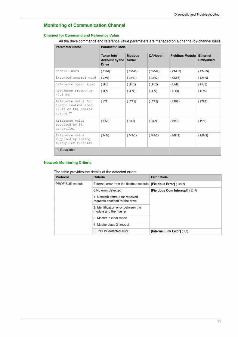
Diagnostic and Troubleshooting
95
Monitoring of Communication Channel
Channel for Command and Reference Value
All the drive commands and reference value parameters are managed on a channel-by-channel basis.
Parameter Name Parameter Code
Taken Into
Account by the
Drive
Modbus
Serial
CANopen Fieldbus Module Ethernet
Embedded
Control word ( CMd) ( CMd1) ( CMd2) ( CMd3) ( CMd5)
Extended control word ( CMI) ( CMI1) ( CMI2) ( CMI3) ( CMI5)
Reference speed (rpm) ( LFd) ( LFd1) ( LFd2) ( LFd3) ( LFd5)
Reference frequency
(0.1 Hz) ( LFr) ( LFr1) ( LFr2) ( LFr3) ( LFr5)
Reference value for
torque control mode
(0.1% of the nominal
torque)(1)
( LTR) ( LTR1) ( LTR2) ( LTR3) ( LTR5)
Reference value
supplied by PI
controller
( PISP) ( PIr1) ( PIr2) ( PIr3) ( PIr5)
Reference value
supplied by analog
multiplier function
( MFr) ( MFr1) ( MFr2) ( MFr3) ( MFr5)
(1): If available
Network Monitoring Criteria
The table provides the details of the detected errors
Protocol Criteria Error Code
PROFIBUS module External error from the fieldbus module [Fieldbus Error] ( EPF2)
0:No error detected [Fieldbus Com Interrupt] ( CnF)
1: Network timeout for received
requests destined for the drive
2: Identification error between the
module and the master
3: Master in clear mode
4: Master class 2 timeout
EEPROM detected error [Internal Link Error] ( ILF)

Diagnostic and Troubleshooting
96
Monitoring of Communication Channels
Communication channels are monitored if they are involved in one of the following parameters: � The
control word ([Cmd Register] ( CMd) ) from the active command channel � The control word
containing the command switch (bit configured on [Cmd switching] ( CCS) ) � The control word
containing the switch for reference value 1’1B (bit configured on [Ref 1B switching]
( rCb) )
� The control word containing the switch for reference value 1’2 (bit configured on [Freq Switch Assign]
( rFC) )
� The reference frequency or reference speed ([Ref Frequency] ( LFr) or LFRD: Nominal speed value)
from the active channel for reference value
� Summing reference frequency or reference speed ([Ref Frequency] ( LFr) or LFRD: Nominal speed
value) 2 (assigned to [Summing Input 2] ( SA2) )
� Summing reference frequency or reference speed ([Ref Frequency] ( LFr) or LFRD: Nominal speed
value) 3 (assigned to [Summing Input 3] ( SA3) )
� Subtracting reference frequency or reference speed ([Ref Frequency] ( LFr) or LFRD: Nominal speed
value) 2 (assigned to [Subtract Ref Freq 2] ( dA2) )
� Subtracting reference frequency or reference speed ([Ref Frequency] ( LFr) or LFRD: Nominal speed
value) 3 (assigned to [Subtract Ref Freq 3] ( dA3) )
� The reference value given by the PID controller (PISP) � The PID controller feedback ([AI Virtual 1]
( AIU1) )
� The multiplication coefficient of the reference values ([Multiplying coeff.] ( MFr) ) 2 (assigned to [Ref
Freq 2 Multiply] ( MA2) ) � The multiplication coefficient of the reference values ([Multiplying coeff.]
( MFr) ) 3 (assigned to [Ref Freq 3 Multiply] ( MA3) )
As soon as one of these parameters has been written once to a communication channel, it activates
monitoring for that channel.
If a communication warning is sent (in accordance with the protocol criteria) by a monitored port or fieldbus
module, the drive triggers a communication interruption.
The drive reacts according to the communication interruption configuration (operating state Fault,
maintenance, fallback, and so on)
If a communication warning occurs on a channel that is not being monitored, the drive does not trigger a
communication interruption.
Enabling of Communication Channels
A communication channel is enabled once all the parameters involved have been written at least one
time.The drive is only able to start if all channels involved in command and reference value are enabled.
For example:
A drive in DSP402 profile is connected to an active communication channel.
It is mandatory to write at least 1 time the reference value and the command in order to switch from
4Switched on to 5-Operation enabled state.
A communication channel is disabled:
� In the event of a communication warning. � In forced local mode.
NOTE: On exiting forced local mode:
� The drive copies the run commands, the direction, and the forced local reference value to the active
channel (maintained).
� Monitoring of the active command and reference value channels resumes following a time delay
[Timeout forc. local] ( FLOt) .
� Drive control only takes effect once the drive has received the reference value and the command from
the active channel.

Diagnostic and Troubleshooting
97
Control-Signal Diagnostics
Introduction
On the display terminal, the [Display] ( MON-) , [Communication map] ( CMM-) submenu can be
used to display control-signal diagnostic information between the drive and the controller: � Active
command channel [Command Channel] ( CMdC)
� Value of the control word [Cmd Register] ( CMd) from the active command channel [Command
Channel] ( CMdC) � Active reference frequency channel [Ref Freq
Channel] ( rFCC)
� Value of the reference frequency [Pre-Ramp Ref Freq] ( FrH) from the active target channel [Ref
Freq Channel] ( rFCC) � Value of the operating state word
[CIA402 State Reg] ( EtA) � Specific data for all available fieldbus
are in dedicated submenus.
� In the [Command word image] ( CWI-) submenu: control words from all channels � In the [Freq. ref.
word map] ( rWI-) submenu: reference frequency values produced by all channels
Control Word Display
The [Command Channel] ( CMdC) parameter indicates the active command channel.
The [Cmd Register] ( CMd) parameter indicates the hexadecimal value of the control word (CMD) used
to control the drive.
The [Command word image] ( CWI-) submenu ([COM. Module cmd.] ( CMd3) ) parameter is used to
display the hexadecimal value of the control word from the fieldbus module.
Reference Frequency Display
The [Ref Freq Channel] ( rFCC) parameter indicates the active channel for reference frequency.
The [Ref Frequency] ( LFr) parameter indicates the value (in 0.1 Hz units) of the reference frequency
used to control the drive.
The [Freq. ref. word map] ( rWI-) submenu ([Com Module Ref Freq] ( LFr3) parameter is used to display
the value (in 0.1 Hz units) of the reference frequency from the fieldbus.
Operating State Word Display
The [CIA402 State Reg] ( EtA) parameter gives the value of the operating state word (ETA).
The table provides the bit details of ETA parameter:
Bit Description
DRIVECOM Status word
Bit0 = 1 Ready to switch on
Bit1 = 1 Switched on
Bit2 = 1 Operation enabled
Bit3 = 1 Operating state fault
Bit4 = 1 Power stage is switched on
Bit5 = 0 Quick stop
Bit6 = 1 Switch on disabled
Bit7 = 1 Warning
Bit8 = 1 Drivecom reserved
Bit9 = 0 Forced local mode in progress
Bit10 = 1 Reference value reached (steady state)
Bit11 = 1 Reference value exceeded (< LSP or > HSP)
Bit12 Reserved
Bit13 Reserved
Bit14 = 1 Stop imposed via STOP key
Bit15 = 0 Motor rotation in forward direction (or stopped)

Diagnostic and Troubleshooting
98

NHA80941 08/2015 99
Altivar Process 900 Glossary
A
Abbreviations
Req. = Required
Opt. = Optional
D
Display terminal
The display terminal menus are shown in square brackets.
For example: [Communication]
The codes are shown in round brackets.
For example: (COM-)
Parameter names are displayed on the display terminal in square brackets.
For example: [Fallback Speed]
Parameter codes are displayed in round brackets. For
example: (LFF)
DP
Decentralized Periphery
E
Error
Discrepancy between a detected (computed, measured, or signaled) value or condition and the specified or
theoretically correct value or condition.
F
Factory setting
Factory settings when the product is shipped
Fault
Fault is an operating state. If the monitoring functions detect an error, a transition to this operating state is
triggered, depending on the error class. A "Fault reset" is required to exit this operating state after the cause
of the detected error has been removed. Further information can be found in the pertinent standards such
as IEC 61800-7, ODVA Common Industrial Protocol (CIP).
Fault Reset
A function used to restore the drive to an operational state after a detected error is cleared by removing the
cause of the error so that the error is no longer active.
M
Monitoring function
Monitoring functions acquire a value continuously or cyclically (for example, by measuring) in order to check
whether it is within permissible limits. Monitoring functions are used for error detection.
MS0, MS1
Number of a master in the network.
P
Parameter
Device data and values that can be read and set (to a certain extent) by the user.
Glossary

100
Glossary
PELV
Protective Extra Low Voltage, low voltage with isolation. For more information: IEC 60364-4-41
PLC
Programmable logic controller
PNO
PROFIBUS Nutzerorganisation e.V. (PROFIBUS User organization).
Power stage
The power stage controls the motor. The power stage generates current for controlling the motor.
Q
Quick Stop
The quick Stop function can be used for fast deceleration of a movement as a response to a detected error
or via a command.
W
Warning
If the term is used outside the context of safety instructions, a warning alerts to a potential problem that was
detected by a monitoring function. A warning does not cause a transition of the operating state.
Z
Zone of operation
This term is used in conjunction with the description of specific hazards, and is defined as it is for a hazard
zone or danger zone in the EC Machinery Directive (2006/42/EC) and in ISO 12100-1.


![PROFIBUS DP bus interface, PROFIBUS DP [BU 2700]...Sicherheit/PROFIBUS DP [BU 2700]/Bestimmungsgemäße Ver wendung PROFIBUS DP @ 8\mod_1461835577600_388.docx @ 2249429 @ 2 @ 1 2.1](https://static.fdocuments.in/doc/165x107/60b54c574bd00c04b50e633d/profibus-dp-bus-interface-profibus-dp-bu-2700-sicherheitprofibus-dp-bu.jpg)