RS485 – PROFIBUS-DP
32
Industrial Switching & Protection Systems ON 1 COM DIRIS Ap RS485 – PROFIBUS ® -DP GB
Transcript of RS485 – PROFIBUS-DP

Industrial Switching & Protection Systems
ON1
COM
DIRIS ApRS485 – PROFIBUS®-DP
GB

2 SOCOMEC - Réf. : 875 514 C
GBCo
nten
ts PRELIMINARY OPERATIONS ___________________ 3GENERAL INFORMATION ______________________ 3INSTALLATION ________________________________ 4PROGRAMMING _______________________________ 5CONFIGURATION ______________________________ 5USE OF PROFIBUS®-DP MODULES _____________ 9DIAGNOSTICS________________________________ 30TECHNICAL CHARACTERISTICS ______________ 31
SOCOMEC - Réf. : 875 514 D 3
EN
GLIS
H
• the product reference number con-forms to your order,
• the package contains 2 option modu-les, the first of which is equipped witha disconnectable terminal block,
• a CD-Rom.
Check the following points as soon asyou receive the package containing thePROFIBUS®-DP option:• the packing is in good condition,• the product has not been damaged
during transit,
NB:For personnel and product safetyplease read the contents of theseoperating instructions carefully beforeconnecting.
PRELIMINARY OPERATIONS
FUNCTIONS
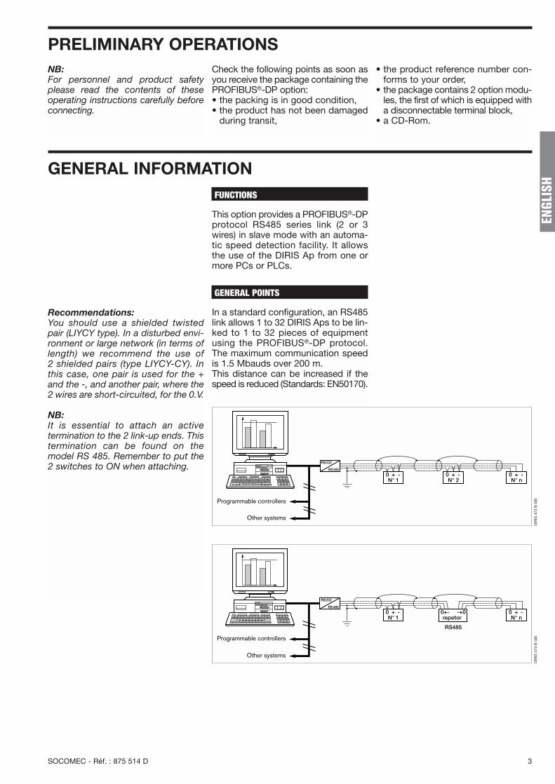
This option provides a PROFIBUS®-DPprotocol RS485 series link (2 or 3wires) in slave mode with an automa-tic speed detection facility. It allowsthe use of the DIRIS Ap from one ormore PCs or PLCs.
GENERAL POINTS
In a standard configuration, an RS485link allows 1 to 32 DIRIS Aps to be lin-ked to 1 to 32 pieces of equipmentusing the PROFIBUS®-DP protocol.The maximum communication speedis 1.5 Mbauds over 200 m.This distance can be increased if thespeed is reduced (Standards: EN50170).
N° 1 N° 2 N° n
Programmable controllers
Other systems
N° 1
Programmable controllers
Other systems
repetor
RS485
0+- -+0N° n
DIR
IS 4
73 B
GB
DIR
IS 4
74 B
GB
Recommendations:You should use a shielded twistedpair (LIYCY type). In a disturbed envi-ronment or large network (in terms oflength) we recommend the use of2 shielded pairs (type LIYCY-CY). Inthis case, one pair is used for the +and the -, and another pair, where the2 wires are short-circuited, for the 0.V.
NB:It is essential to attach an active termination to the 2 link-up ends. Thistermination can be found on themodel RS 485. Remember to put the2 switches to ON when attaching.
GENERAL INFORMATION

4 SOCOMEC - Réf. : 875 514 C
INSTALLATIONThe option modules are installed onthe rear panel of the DIRIS Ap in oneof the four positions provided.
CONNECTION
DIR
IS 4
70 A
1
DIR
IS 4
71 A
2 Fix the option modules next to each other
4 Follow indications when connecting the terminalSwitch on voltage supply
ON1
ON1
0V - +
COM
DIR
IS 4
69 B
3
The DIRIS Ap must be switched off
Note:Correspondence with a HAN BRIDconnector+ = B (red)- = A (green)
SOCOMEC - Réf. : 875 514 D 5
EN
GLIS
H
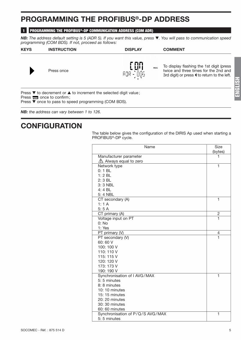
PROGRAMMING THE PROFIBUS®-DP ADDRESSPROGRAMMING THE PROFIBUS®-DP COMMUNICATION ADDRESS (COM ADR)1
NB: The address default setting is 5 (ADR 5). If you want this value, press ▼. You will pass to communication speedprogramming (COM BDS). If not, proceed as follows:
KEYS INSTRUCTION DISPLAY COMMENT
Press onceTo display flashing the 1st digit (presstwice and three times for the 2nd and3rd digit) or press � to return to the left.
Press ▼ to decrement or ▲ to increment the selected digit value ;Press once to confirm;Press ▼ once to pass to speed programming (COM BDS).
NB: the address can vary between 1 to 126.
CONFIGURATIONThe table below gives the configuration of the DIRIS Ap used when starting aPROFIBUS®-DP cycle.
Name Size (bytes)
Manufacturer parameter 1Always equal to zero
Network type 10: 1 BL1: 2 BL2: 3 BL3: 3 NBL4: 4 BL5: 4 NBLCT secondary (A) 11: 1 A5: 5 ACT primary (A) 2Voltage input on PT 10: No1: YesPT primary (V) 4PT secondary (V) 160: 60 V100: 100 V110: 110 V115: 115 V120: 120 V173: 173 V190: 190 VSynchronisation of I AVG/MAX 15: 5 minutes8: 8 minutes10: 10 minutes15: 15 minutes20: 20 minutes30: 30 minutes60: 60 minutesSynchronisation of P/Q/S AVG/MAX 15: 5 minutes
6 SOCOMEC - Réf. : 875 514 C
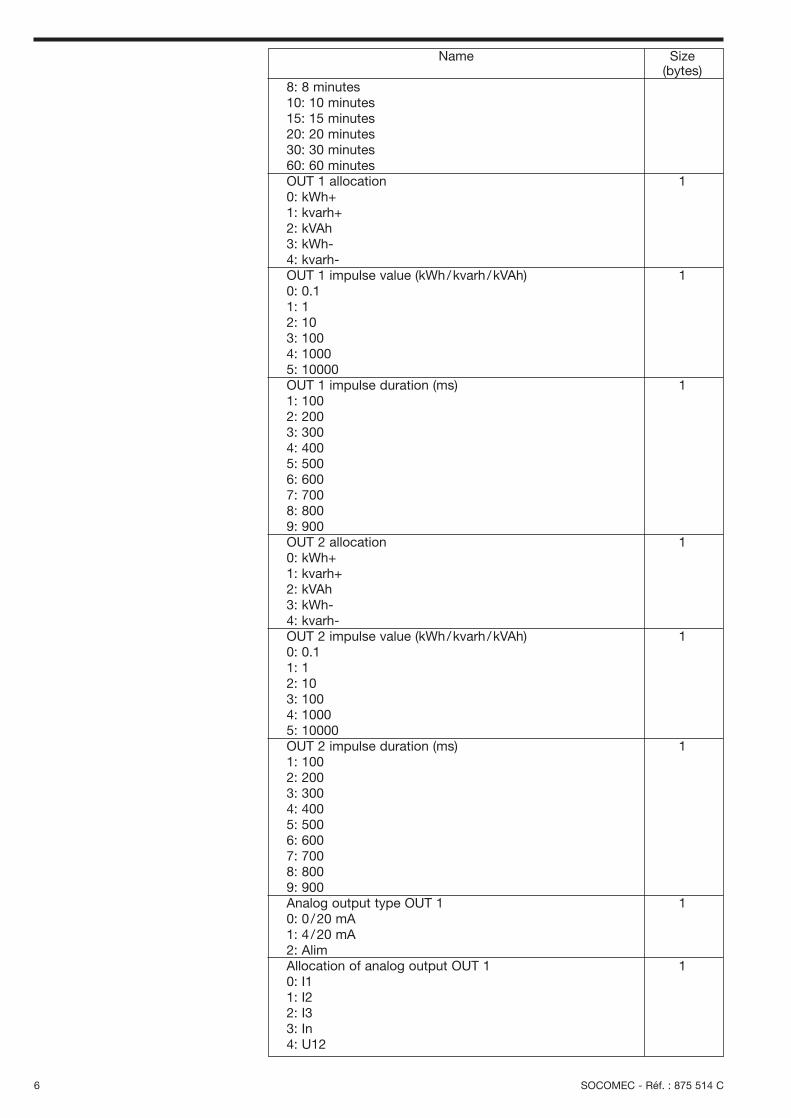
8: 8 minutes10: 10 minutes15: 15 minutes20: 20 minutes30: 30 minutes60: 60 minutesOUT 1 allocation 10: kWh+1: kvarh+2: kVAh3: kWh-4: kvarh-OUT 1 impulse value (kWh/kvarh/kVAh) 10: 0.11: 12: 103: 1004: 10005: 10000OUT 1 impulse duration (ms) 11: 1002: 2003: 3004: 4005: 5006: 6007: 7008: 8009: 900OUT 2 allocation 10: kWh+1: kvarh+2: kVAh3: kWh-4: kvarh-OUT 2 impulse value (kWh/kvarh/kVAh) 10: 0.11: 12: 103: 1004: 10005: 10000OUT 2 impulse duration (ms) 11: 1002: 2003: 3004: 4005: 5006: 6007: 7008: 8009: 900Analog output type OUT 1 10: 0 /20 mA1: 4 /20 mA2: Alim Allocation of analog output OUT 1 10: I11: I22: I3 3: In4: U12
Name Size (bytes)

SOCOMEC - Réf. : 875 514 D 7
EN
GLIS
H
5: U236: U317: P8: Q9: S10: PF11: V112: V213: V314: FValue at 0 or 4 mA from analog output OUT 1 2Unit at 0 or 4 mA from analog output OUT 1 10: /1: k2: MValue at 20 mA from analog output OUT 1 2Unit at 20 mA from analog output OUT 1 10: /1: k2: MAnalog output type OUT 2 10: 0 /20 mA1: 4 /20 mA2: SupplyAllocation of analog output OUT 2 10: I11: I22: I3 3: In4: U125: U236: U317: P8: Q9: S10: PF11: V112: V213: V314: FValue at 0 or 4 mA from analog output OUT 2 2Unit at 0 or 4 mA from analog output OUT 2 10: /1: k2: MValue at 20 mA from analog output OUT 2 2Unit at 20 mA from analog output OUT 2 10: /1: k2: MAnalog output type OUT 3 10: 0 /20 mA1: 4 /20 mA2: Supply Allocation of analog output OUT 3 10: I11: I22: I3 3: In4: U125: U23
Name Size (bytes)

8 SOCOMEC - Réf. : 875 514 D
Name Size (bytes)
6: U317: P8: Q9: S10: PF11: V112: V213: V314: FValue at 0 or 4 mA from analog output OUT 3 2Unit at 0 or 4 mA from analog output OUT 3 10: /1: k2: MValue at 20 mA from analog output OUT 3 2Unit at 20 mA from analog output OUT 3 10: /1: k2: MAnalog output type OUT 4 10: 0 /20 mA1: 4 /20 mA2: Supply Allocation of analog output OUT 4 10: I11: I22: I3 3: In4: U125: U236: U317: P8: Q9: S10: PF11: V112: V213: V314: FValue at 0 or 4 mA from analog output OUT 4 2Unit at 0 or 4 mA from analog output OUT 4 10: /1: k2: MValue at 20 mA from analog output OUT 4 2Unit at 20 mA from analog output OUT 4 10: /1: k2: MCT In secondary (A) 11: 1 A5: 5 ACT In primary (A) 2
Length: 54 bytes
Check that the parameterisation data are identical to the dataprogrammed in the device.
NB:All this information is integrated in theGSD file (User-Prm-Data).

SOCOMEC - Réf. : 875 514 D 9
EN
GLIS
H
USE OF THE PROFIBUS®-DP MODULESThe modules contain the inputs (display) and outputs (configuration).
Change of relay status if bit on 1, then taken into account, otherwise bit on 0 1bit 0: Relay 1bit 1: Relay 2bit 2: Relay 3 (second option relay 1)bit 3: Relay 4 (second option relay 2)bit 4: Change in relay configurationbit 5: Resetting of one measurementbit 6: not usedbit 7: not usedRelay 1 on break 10: open1: closedRelay 2 on break 10: open1: closedRelay 3 on break 10: open1: closedRelay 4 on break 10: open1: closedAllocation OUT 1 10: Cde1: I2: U3: P+4: Q+5: S6: F7: PFL8: Thd 3I9: Thd 3U10: In11: time12: V13: Thd In14: Thd 3V15: P-16: Q-17: PFCLower threshold OUT 1 2Lower threshold unit OUT 1 10: /1: k2: MUpper threshold OUT 1 2Upper threshold unit OUT 1 10: /1: k2: MHysteresis 0 to 99 OUT 1 (%) 1Time delay OUT 1 (s) 2
Name Size (bytes)
Output frame
MODULE 1: MAIN MEASUREMENTS1
This module contains the currents, powers, frequencies, power factor, positiveenergies and hour meter.
Example: Modification of relay 1: • set bit 4 (relay configuration change),• set bit 0 (relay 1 to 1),• modify the status byte on relay 1
break (next byte).
10 SOCOMEC - Réf. : 875 514 C
Allocation OUT 2 10: Cde1: I2: U3: P+4: Q+5: S6: F7: PFL8: Thd 3I9: Thd 3U10: In11: time12: V13: Thd In14: Thd 3V15: P-16: Q-17: PFCLower threshold OUT 2 2Lower threshold unit OUT 2 10: /1: k2: MUpper threshold OUT 2 2Upper threshold unit OUT 2 10: /1: k2: MHysteresis 0 to 99 OUT 2 (%) 1Time delay OUT 2 (s) 2Zero reset 2bit 0: Max 3Ibit 1: Max P+bit 2: Max P-bit 3: Max Q+bit 4: Max Q-bit 5: Max Sbit 6: hour meterbit 7: kWh+bit 8: kvarh+bit 9: kVAbit 10: kWh-bit 11: kvarh-bit 12: all the parametersbit 13: Input 1bit 14: Input2bit 15: not usedZero reset, supplementary options 2bit 0: Input 1bit 1: Input 2bit 2: Input 3bit 3: Input 4bit 4: Not usedbit 5: Not usedbit 6: Min Max Ibit 7: Min Max Inbit 8: Min Max Ubit 9: Min Max Frequency bit 10: Min Max PFbit 11: Min Max Pbit 12: Min Max Qbit 13: Min Max Thd Ibit 14: Min Max Thd Inbit 15: Min Max Thd U
Name Size (bytes)
Length: 29 bytes

SOCOMEC - Réf. : 875 514 D 11
EN
GLIS
H
Length: 68 bytes
Frame of inputs not allocated for current and voltage transformationratios
Phase 1 current (mA) 2Phase 2 current (mA) 2Phase 3 current (mA) 2Neutral current (mA) 2Phase to phase voltage U12 (V /100) 2Phase to phase voltage U23 (V /100) 2Phase to phase voltage U31 (V /100) 2Phase to neutral voltage phase 1 (V /100) 2Phase to neutral voltage phase 2 (V /100) 2Phase to neutral voltage phase 3 (V /100) 2Frequency (Hz/100) 2∑ Active power +/- (kW/10) 2∑ Reactive power +/- (kvar /10) 2∑ Apparent power +/- (kVa/10) 2∑ Power factor L /C 2-: capacitive and +: inductive (0.001)I1 max (mA) 2I2 max (mA) 2I3 max (mA) 2Maximum value active power + (kW/100) 2Maximum value active power – (kW/100) 2Maximum value reactive power + (kvar /100) 2Maximum value reactive power – (kvar /100) 2Maximum apparent power (kVA/100) 2Active energy + < 10000 (kWh) 2Active energy + > 10000 (kWh) 2Reactive energy + < 10000 (kvarh) 2Reactive energy + > 10000 (kvarh) 2Apparent energy < 10000 (kVAh) 2Apparent energy > 10000 (kVAh) 2System I (mA) 2System U (V /100) 2System V (V /100) 2Hour meter < 10000 (H/100) 2Hour meter >10000 (H/100) 2
Name Size (bytes)
Calculation of the values allocated:The currents must be multiplied by theCT ratio, the voltages by the PT ratio (inHV) and the powers by the ratio CT x PT.Example:
CT = 100 = 20 VT = 20000 = 2005 100
CT x VT = 20 x 200= 4000
Powers will be multiplied by 4000 (ifthere is no VT, then VT = 1), currentsby 20 and voltages by 200.
Nota:System I = I1 + I2 + I3
3
System U = U12 + U21 + U313
System V = V1 + V2 + V33
Transformation of signed values into unsigned values
If the currents, voltages or energies are negative, the following rule must beapplied:• take the opposite bit by bit of the datum• add 1 to this oppositeExample:• negative datum –28864mv or in binary 1001 0111 0001 0000• opposite is equal to 0110 1000 1110 1111• opposite + 1 is equal to 0110 1000 1111 0000 or in decimal 386.72V.

12 SOCOMEC - Réf. : 875 514 C
Active power phase 1 +/- (kW/10) 2Active power phase 2 +/- (kW/10) 2Active power phase 3 +/- (kW/10) 2Reactive power phase 1 +/- (kvar /10) 2Reactive power phase 2 +/- (kvar /10) 2Reactive power phase 3 +/- (kvar /10) 2Apparent power phase 1 (kVA/10) 2Apparent power phase 2 (kVA/10) 2Apparent power phase 3 (kVA/10) 2Power factor phase 1 (0.001) 2-: capacitive and +: inductivePower factor phase 2 (0.001) 2-: capacitive and +: inductivePower factor phase 3 (0.001) 2-: capacitive and +: inductive Average value I1 (mA) 2Average value I2 (mA) 2Average value I3 (mA) 2Average value active power + (kW/100) 2Average value active power - (kW/100) 2Average value reactive power + (kvar /100) 2Average value reactive power - (kvar /100) 2Average value apparent power (kVA/100) 2Active energy - < 10000 (kWh) 2Active energy - >10000 (kWh) 2Reactive energy - < 10000 (kvarh) 2Reactive energy - > 10000 (kvarh) 2Input pulse meter 1 < 10000 2Input pulse meter 1 > 10000 2Input pulse meter 2 < 10000 2Input pulse meter 2 > 10000 2Input pulse meter 3 < 10000 2Input pulse meter 3 > 10000 2Input pulse meter 4 < 10000 2Input pulse meter 4 > 10000 2Status inputs 1, 2, 3, 4. 2
Name Size (bytes)
Length: 66 bytes
Input frame
MODULE 2: SUPPLEMENTARY MEASUREMENTS2
This module contains the measurements by phase, average values, negativeenergies, impulse meters (on/off inputs) and statuses (on/off inputs). The output frame is identical to module 1.
Calculation of the values allocated:The currents must be multiplied by theCT ratio, the voltages by the PT ratio (inHV) and the powers by the CT x PTratio.Example:
CT = 100 = 20 VT = 20000 = 2005 100
CT x VT = 20 x 200= 4000
Powers will be multiplied by 4000 (ifthere is no VT, then VT = 1), currentsby 20 and voltages by 200.
Status of the inputs :input 1 = bit 0input 2 = bit 1input 3 = bit 2input 4 = bit 4
If active the bit is on 1.If inactive the bit is on 0.
Transformation of signed values into unsigned values
If the currents, voltages or energies are negative, the following rule must beapplied:• take the opposite bit by bit of the datum• add 1 to this oppositeExample:• negative datum –28864mv or in binary 1001 0111 0001 0000• opposite is equal to 0110 1000 1110 1111• opposite + 1 is equal to 0110 1000 1111 0000 or in decimal 386.72V.

SOCOMEC - Réf. : 875 514 D 13
EN
GLIS
H
Lower threshold Alarm 1 10: no alarm 1: I12: I23: I34: In5: U126: U237: U318: P9: Q10: S11: F12: PF15: Thd I116: Thd I217: Thd I318: Thd U1219: Thd U2320: Thd U3121: time22: V123: V224: V325: Thd In26: Thd V127: Thd V228: Thd V329: P-30: Q-31: CPFLower value threshold Alarm 1 4Upper threshold Alarm 1 10: no alarm1: I12: I23: I34: In5: U126: U237: U318: P9: Q10: S11: F12: PF15: Thd I116: Thd I217: Thd I318: Thd U1219: Thd U2320: Thd U3121: time22: V123: V224: V325: Thd In26: Thd V127: Thd V228: Thd V329: P-30: Q-31: CPF
Name Size (bytes)
MODULE 3: STORED ALARMS RELAY 13
This module contains the alarm log for relay 1The output frame is identical to module1.Input frame

14 SOCOMEC - Réf. : 875 514 C
Upper value threshold Alarm 1 4Alarm duration (s) 2Lower threshold Alarm 2 10: no alarm 1: I12: I23: I34: In5: U126: U237: U318: P9: Q10: S11: F12: PF15: Thd I116: Thd I217: Thd I318: Thd U1219: Thd U2320: Thd U3121: time22: V123: V224: V325: Thd In26: Thd V127: Thd V228: Thd V329: P-30: Q-31: CPFLower value threshold Alarm 2 4Upper threshold Alarm 2 10: no alarm 1: I12: I23: I34: In5: U126: U237: U318: P9: Q10: S11: F12: PF15: Thd I116: Thd I217: Thd I318: Thd U1219: Thd U2320: Thd U3121: time22: V123: V224: V325: Thd In26: Thd V127: Thd V228: Thd V329: P-30: Q-31: CPFUpper value threshold Alarm 2 4Alarm 2 duration (s) 2
Name Size (bytes)

SOCOMEC - Réf. : 875 514 D 15
EN
GLIS
H
Lower threshold Alarm 3 10: no alarm1: I12: I23: I34: In5: U126: U237: U318: P9: Q10: S11: F12: PF15: Thd I116: Thd I217: Thd I318: Thd U1219: Thd U2320: Thd U3121: time22: V123: V224: V325: Thd In26: Thd V127: Thd V228: Thd V329: P-30: Q-31: CPFLower value threshold Alarm 3 4Upper threshold Alarm 3 10: no alarm1: I12: I23: I34: In5: U126: U237: U318: P9: Q10: S11: F12: PF15: Thd I116: Thd I217: Thd I318: Thd U1219: Thd U2320: Thd U3121: time22: V123: V224: V325: Thd In26: Thd V127: Thd V228: Thd V329: P-30: Q-31: CPFUpper value threshold Alarm 3 4Alarm 3 duration (s) 2
Name Size (bytes)
Length: 36 bytes

16 SOCOMEC - Réf. : 875 514 C
Lower threshold Alarm 1 10: no alarm1: I12: I23: I34: In5: U126: U237: U318: P9: Q10: S11: F12: PF15: Thd I116: Thd I217: Thd I318: Thd U1219: Thd U2320: Thd U3121: time22: V123: V224: V325: Thd In26: Thd V127: Thd V228: Thd V329: P-30: Q-31: CPFLower value threshold Alarm 1 4Upper threshold Alarm 1 10: no alarm1: I12: I23: I34: In5: U126: U237: U318: P9: Q10: S11: F12: PF15: Thd I116: Thd I217: Thd I318: Thd U1219: Thd U2320: Thd U3121: time22: V123: V224: V325: Thd In26: Thd V127: Thd V228: Thd V329: P-30: Q-31: CPFUpper value threshold Alarm 1 4
Name Size (bytes)
MODULE 4: STORED ALARMS RELAY 24
This module contains the storage of the alarms for relay 2. The output frame is identical to module1.Input frame

SOCOMEC - Réf. : 875 514 D 17
EN
GLIS
H
Alarm 1 duration (s) 2Lower threshold Alarm 2 10: no alarm1: I12: I23: I34: In5: U126: U237: U318: P9: Q10: S11: F12: PF15: Thd I116: Thd I217: Thd I318: Thd U1219: Thd U2320: Thd U3121: time22: V123: V224: V325: Thd In26: Thd V127: Thd V228: Thd V329: P-30: Q-31: CPFLower value threshold Alarm 2 4Upper threshold Alarm 2 10: no alarm1: I12: I23: I34: In5: U126: U237: U318: P9: Q10: S11: F12: PF15: Thd I116: Thd I217: Thd I318: Thd U1219: Thd U2320: Thd U3121: time22: V123: V224: V325: Thd In26: Thd V127: Thd V228: Thd V329: P-30: Q-31: CPFUpper value threshold Alarm 2 4Alarm 2 duration (s) 2
Name Size (bytes)
Input frame

18 SOCOMEC - Réf. : 875 514 C
Lower threshold Alarm 3 10: no alarm1: I12: I23: I34: In5: U126: U237: U318: P9: Q10: S11: F12: PF15: Thd I116: Thd I217: Thd I318: Thd U1219: Thd U2320: Thd U3121: time22: V123: V224: V325: Thd In26: Thd V127: Thd V228: Thd V329: P-30: Q-31: CPFLower value threshold Alarm 3 4Upper threshold Alarm 3 10: no alarm1: I12: I23: I34: In5: U126: U237: U318: P9: Q10: S11: F12: PF15: Thd I116: Thd I217: Thd I318: Thd U1219: Thd U2320: Thd U3121: time22: V123: V224: V325: Thd In26: Thd V127: Thd V228: Thd V329: P-30: Q-31: CPFUpper value threshold Alarm 3 4Alarm 3 duration (s) 2
Name Size (bytes)
Length: 36 bytes
Input frame

SOCOMEC - Réf. : 875 514 D 19
EN
GLIS
H
Thd I1 (0.1%) 2Thd I2 (0.1%) 2Thd I3 (0.1%) 2Thd In (0.1%) 2Harmonic I1 row 3 (0.1%) 2Harmonic I2 row 3 (0.1%) 2Harmonic I3 row 3 (0.1%) 2Harmonic In row 3 (0.1%) 2Harmonic I1 row 5 (0.1%) 2Harmonic I2 row 5 (0.1%) 2Harmonic I3 row 5 (0.1%) 2Harmonic In row 5 (0.1%) 2Harmonic I1 row 7 (0.1%) 2Harmonic I2 row 7 (0.1%) 2Harmonic I3 row 7 (0.1%) 2Harmonic In row 7 (0.1%) 2Harmonic I1 row 9 (0.1%) 2Harmonic I2 row 9 (0.1%) 2Harmonic I3 row 9 (0.1%) 2Harmonic In row 9 (0.1%) 2Harmonic I1 row 11 (0.1%) 2Harmonic I2 row 11 (0.1%) 2Harmonic I3 row 11 (0.1%) 2Harmonic In row 11 (0.1%) 2Harmonic I1 row 13 (0.1%) 2Harmonic I2 row 13 (0.1%) 2Harmonic I3 row 13 (0.1%) 2Harmonic In row 13 (0.1%) 2Harmonic I1 row 15 (0.1%) 2Harmonic I2 row 15 (0.1%) 2Harmonic I3 row 15 (0.1%) 2Harmonic In row 15 (0.1%) 2
Name Size (bytes)
MODULE 5: CURRENT HARMONICS5
This module contains the thd Is, the thd INs and the individual harmonics upto number 15. The output frame is identical to module 1.
Length: 64 bytes
Input frameNB:The individual harmonics are availableif the harmonic module is connected.

20 SOCOMEC - Réf. : 875 514 C
Thd U12 (0.1%) 2Thd U23 (0.1%) 2Thd U31 (0.1%) 2Harmonic U12 row 3 (0.1%) 2Harmonic U23 row 3 (0.1%) 2Harmonic U31 row 3 (0.1%) 2Harmonic U12 row 5 (0.1%) 2Harmonic U23 row 5 (0.1%) 2Harmonic U31 row 5 (0.1%) 2Harmonic U12 row 7 (0.1%) 2Harmonic U23 row 7 (0.1%) 2Harmonic U31 row 7 (0.1%) 2Harmonic U12 row 9 (0.1%) 2Harmonic U23 row 9 (0.1%) 2Harmonic U31 row 9 (0.1%) 2Harmonic U12 row 11 (0.1%) 2Harmonic U23 row 11 (0.1%) 2Harmonic U31 row 11 (0.1%) 2Harmonic U12 row 13 (0.1%) 2Harmonic U23 row 13 (0.1%) 2Harmonic U31 row 13 (0.1%) 2Harmonic U12 row 15 (0.1%) 2Harmonic U23 row 15 (0.1%) 2Harmonic U31 row 15 (0.1%) 2
Name Size (bytes)
MODULE 6: PHASE TO PHASE VOLTAGE HARMONICS6
This module contains the thd 3U and the individual harmonics up to number 15.The output frame is identical to module 1.
Input frameNB:The individual harmonics are availableif the harmonic module is connected.
Thd V1 (0.1%) 2Thd V2 (0.1%) 2Thd V3 (0.1%) 2Harmonic V1 row 3 (0.1%) 2Harmonic V2 row 3 (0.1%) 2Harmonic V3 row 3 (0.1%) 2Harmonic V1 row 5 (0.1%) 2Harmonic V2 row 5 (0.1%) 2Harmonic V3 row 5 (0.1%) 2Harmonic V1 row 7 (0.1%) 2Harmonic V2 row 7 (0.1%) 2Harmonic V3 row 7 (0.1%) 2Harmonic V1 row 9 (0.1%) 2Harmonic V2 row 9 (0.1%) 2Harmonic V3 row 9 (0.1%) 2Harmonic V1 row 11 (0.1%) 2Harmonic V2 row 11 (0.1%) 2Harmonic V3 row 11 (0.1%) 2Harmonic V1 row 13 (0.1%) 2Harmonic V2 row 13 (0.1%) 2Harmonic V3 row 13 (0.1%) 2Harmonic V1 row 15 (0.1%) 2Harmonic V2 row 15 (0.1%) 2Harmonic V3 row 15 (0.1%) 2
Name Size (bytes)
MODULE 7: PHASE TO NEUTRAL VOLTAGE HARMONICS7
This module contains the thd 3V and the individual harmonics up to number 15.The output frame is identical to module 1.
Input frameNB:The individual harmonics are availableif the harmonic module is connected.
Length: 48 bytes
Length: 48 bytes

SOCOMEC - Réf. : 875 514 D 21
EN
GLIS
H
Min. current (mA) 2Min. neutral current (mA) 2Min. phase to phase voltage (V /100) 2Min. frequency (Hz/100) 2Min. power factor (0.001) 2Min. active power (kW/100) 2Min. reactive power (kvar /100) 2Thd I min (0.1%) 2Thd In min (0.1%) 2Thd U min (0.1%) 2Max. current (mA) 2Max. neutral current (mA) 2Max. phase to phase voltage (V /100) 2Max. frequency (Hz/100) 2Max. power factor (0.001) 2Max. active power (kW/100) 2Max. reactive power (kvar /100) 2Thd I max (0.1%) 2Thd In max (0.1%) 2Thd U max (0.1%) 2
Name Size (bytes)
MODULE 8: MIN/MAX INSTANTS8
This module contains the storage of the minimum and maximum values (if the2 input /2 output module is installed). The output frame is identical to module 1.
Input frame
Length: 40 bytes
Change of relay status if bit on 1, then taken into account, otherwise bit on 0 1bit 0: Relay 1bit 1: Relay 2bit 2: Relay 3 (second option relay 1)bit 3: Relay 4 (second option relay 1)bit 4: change in relay configurationbit 5: resetting of one measurementbit 6: not usedbit 7: 0 -> configuration frameRelay 1 on break 10: open1: closedRelay 2 on break 10: open
1: closedRelay 3 on break 10: open1: closedRelay 4 on break 10: open1: closedAllocation OUT 1 10: Command1: I
Name Size (bytes)
MODULE 9: SPECIAL FRAME9
This module allows the creation of a personalised module.
Output frameIf bit 7 is on 0, then the output frame is a normal frame
Example:Modification of relay 1 :•set bit 4 (relay configuration change),•set bit 0 (relais 1 à 1),• modify the status byte on relay 1
break (next byte).
22 SOCOMEC - Réf. : 875 514 C
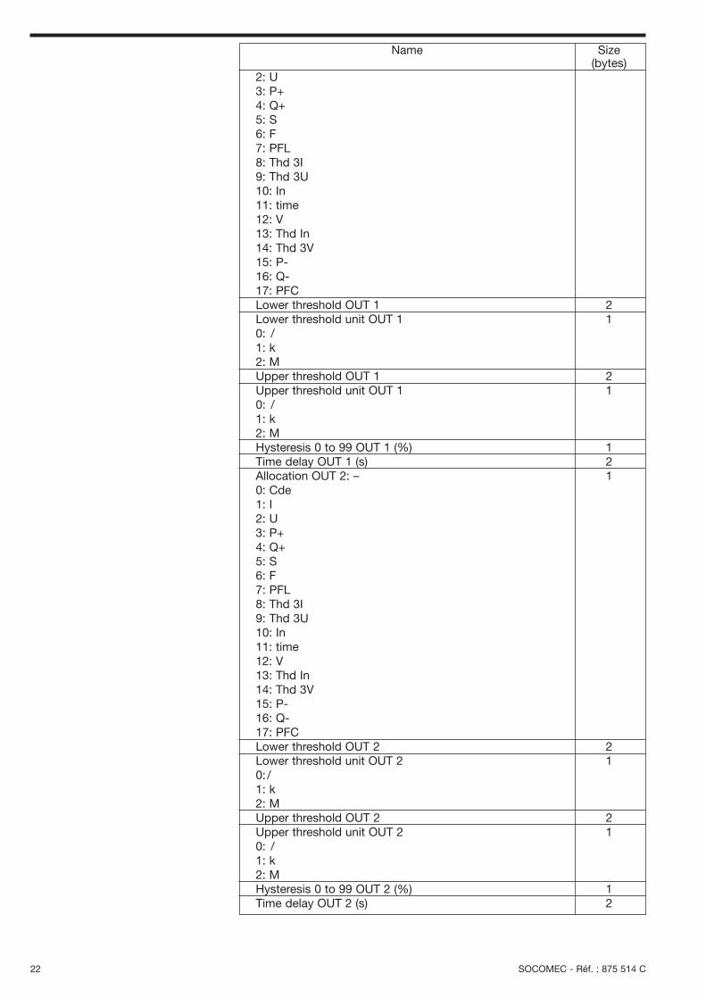
2: U3: P+4: Q+5: S6: F7: PFL8: Thd 3I9: Thd 3U10: In11: time12: V13: Thd In14: Thd 3V15: P-16: Q-17: PFCLower threshold OUT 1 2Lower threshold unit OUT 1 10: /1: k2: MUpper threshold OUT 1 2Upper threshold unit OUT 1 10: /1: k2: MHysteresis 0 to 99 OUT 1 (%) 1Time delay OUT 1 (s) 2Allocation OUT 2: – 10: Cde1: I2: U3: P+4: Q+5: S6: F7: PFL8: Thd 3I9: Thd 3U10: In11: time12: V13: Thd In14: Thd 3V15: P-16: Q-17: PFCLower threshold OUT 2 2Lower threshold unit OUT 2 10: /1: k2: MUpper threshold OUT 2 2Upper threshold unit OUT 2 10: /1: k2: MHysteresis 0 to 99 OUT 2 (%) 1Time delay OUT 2 (s) 2
Name Size (bytes)
SOCOMEC - Réf. : 875 514 D 23
EN
GLIS
H
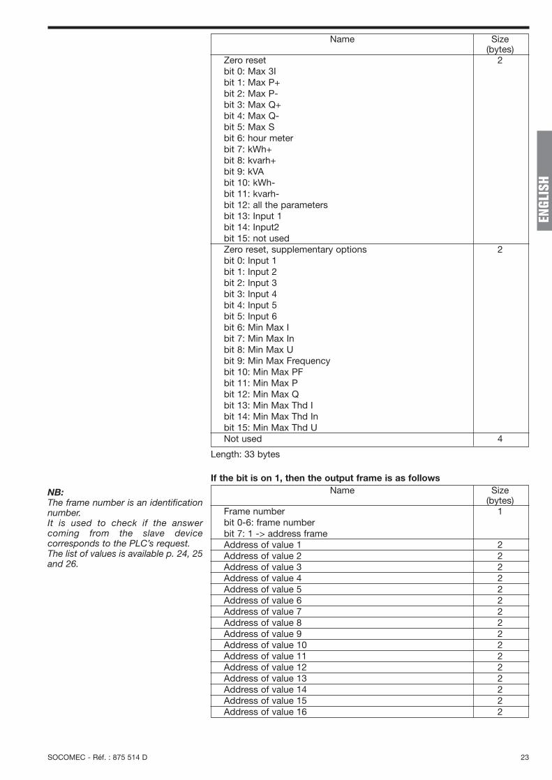
Zero reset 2bit 0: Max 3Ibit 1: Max P+bit 2: Max P-bit 3: Max Q+bit 4: Max Q-bit 5: Max Sbit 6: hour meterbit 7: kWh+bit 8: kvarh+bit 9: kVAbit 10: kWh-bit 11: kvarh-bit 12: all the parametersbit 13: Input 1bit 14: Input2bit 15: not usedZero reset, supplementary options 2bit 0: Input 1bit 1: Input 2bit 2: Input 3bit 3: Input 4bit 4: Input 5bit 5: Input 6bit 6: Min Max Ibit 7: Min Max Inbit 8: Min Max Ubit 9: Min Max Frequencybit 10: Min Max PFbit 11: Min Max Pbit 12: Min Max Qbit 13: Min Max Thd Ibit 14: Min Max Thd Inbit 15: Min Max Thd UNot used 4
Name Size (bytes)
Frame number 1bit 0-6: frame number bit 7: 1 -> address frameAddress of value 1 2Address of value 2 2Address of value 3 2Address of value 4 2Address of value 5 2Address of value 6 2Address of value 7 2Address of value 8 2Address of value 9 2Address of value 10 2Address of value 11 2Address of value 12 2Address of value 13 2Address of value 14 2Address of value 15 2Address of value 16 2
Name Size (bytes)
If the bit is on 1, then the output frame is as follows
Length: 33 bytes
NB:The frame number is an identificationnumber. It is used to check if the answercoming from the slave device corresponds to the PLC’s request.The list of values is available p. 24, 25and 26.

24 SOCOMEC - Réf. : 875 514 C
Phase 1 current 0 0000Phase 2 current 1 0001Phase 3 current 2 0002Neutral current 3 0003Phase to phase voltage U12 4 0004Phase to phase voltage U23 5 0005Phase to phase voltage U31 6 0006Phase to neutral voltage phase 1 7 0007Phase to neutral voltage phase 2 8 0008Phase to neutral voltage phase 3 9 0009Frequency 10 000A_ Active power 11 000B_ Reactive power 12 000C_ Apparent power 13 000D_ Power factor L /C 14 000EMax. value I1 15 000FMax. value I2 16 0010Max. value I3 17 0011Maximum value active power + 18 0012Maximum value active power - 19 0013Maximum value reactive power + 20 0014Maximum value reactive power - 21 0015Maximum value apparent power 22 0016Active energy + < 10000 23 0017Active energy + > 10000 24 0018Reactive energy + < 10000 25 0019Reactive energy + > 10000 26 001AApparent energy < 10000 27 001BApparent energy > 10000 28 001CActive power phase 1 29 001DActive power phase 2 30 001EActive power phase 3 31 001FReactive power phase 1 32 0020Reactive power phase 2 33 0021Reactive power phase 3 34 0022Apparent power phase 1 35 0023Apparent power phase 2 36 0024Apparent power phase 3 37 0025Power factor phase 1 38 0026Power factor phase 2 39 0027Power factor phase 3 40 0028Average value I1 41 0029Average value I2 42 002AAverage value I3 43 002BAverage value active power + 44 002CAverage value active power - 45 002DAverage value reactive power + 46 002EAverage value reactive power - 47 002FAverage value Apparent power 48 0030Active energy - < 10000 49 0031Active energy - >10000 50 0032Reactive energy - < 10000 51 0033Reactive energy - > 10000 52 0034Input pulse meter 1 < 10000 53 0035Input pulse meter 1 > 10000 54 0036Input pulse meter 2 < 10000 55 0037Input pulse meter 2 > 10000 56 0038Input pulse meter 3 < 10000 57 0039Input pulse meter 3 > 10000 58 003AInput pulse meter 4 < 10000 59 003BInput pulse meter 4 > 10000 60 003CStatus inputs 1 2 3 4 61 003DThd I1 62 003EThd I2 63 003F
MeasurementsName Decimal Hexa.
address address
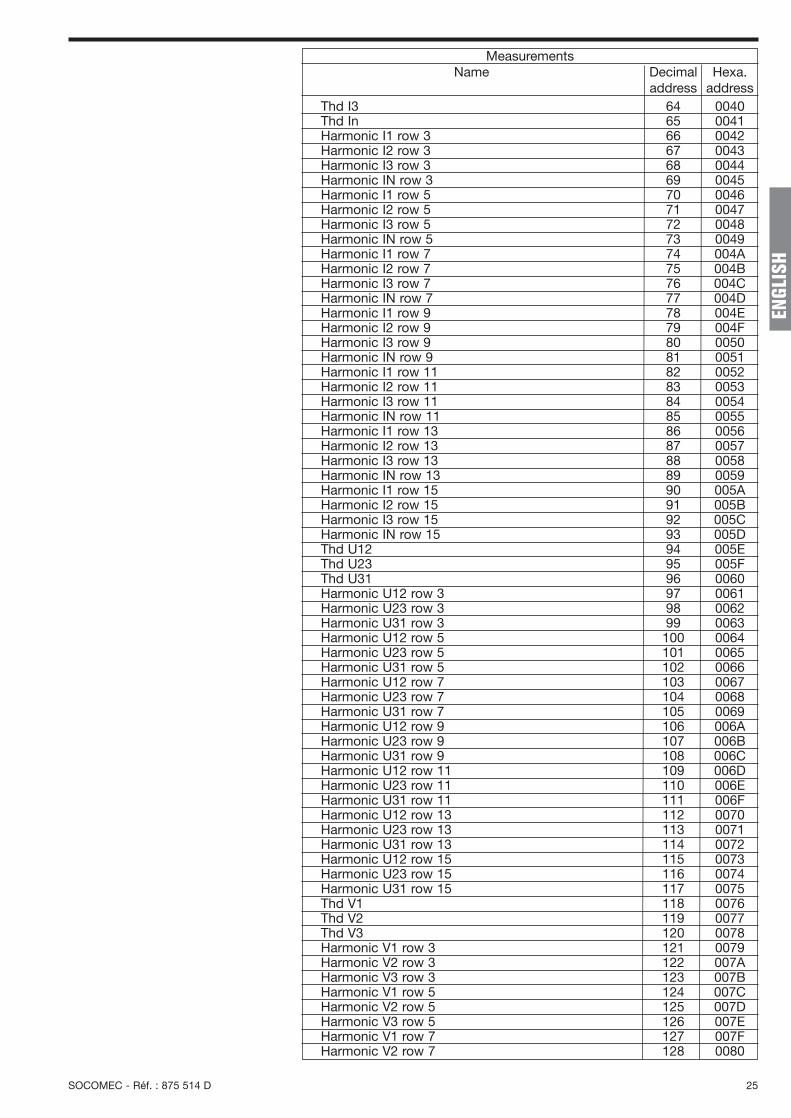
List of values
SOCOMEC - Réf. : 875 514 D 25
EN
GLIS
H
Thd I3 64 0040Thd In 65 0041Harmonic I1 row 3 66 0042Harmonic I2 row 3 67 0043Harmonic I3 row 3 68 0044Harmonic IN row 3 69 0045Harmonic I1 row 5 70 0046Harmonic I2 row 5 71 0047Harmonic I3 row 5 72 0048Harmonic IN row 5 73 0049Harmonic I1 row 7 74 004AHarmonic I2 row 7 75 004BHarmonic I3 row 7 76 004CHarmonic IN row 7 77 004DHarmonic I1 row 9 78 004EHarmonic I2 row 9 79 004FHarmonic I3 row 9 80 0050Harmonic IN row 9 81 0051Harmonic I1 row 11 82 0052Harmonic I2 row 11 83 0053Harmonic I3 row 11 84 0054Harmonic IN row 11 85 0055Harmonic I1 row 13 86 0056Harmonic I2 row 13 87 0057Harmonic I3 row 13 88 0058Harmonic IN row 13 89 0059Harmonic I1 row 15 90 005AHarmonic I2 row 15 91 005BHarmonic I3 row 15 92 005CHarmonic IN row 15 93 005DThd U12 94 005EThd U23 95 005FThd U31 96 0060Harmonic U12 row 3 97 0061Harmonic U23 row 3 98 0062Harmonic U31 row 3 99 0063Harmonic U12 row 5 100 0064Harmonic U23 row 5 101 0065Harmonic U31 row 5 102 0066Harmonic U12 row 7 103 0067Harmonic U23 row 7 104 0068Harmonic U31 row 7 105 0069Harmonic U12 row 9 106 006AHarmonic U23 row 9 107 006BHarmonic U31 row 9 108 006CHarmonic U12 row 11 109 006DHarmonic U23 row 11 110 006EHarmonic U31 row 11 111 006FHarmonic U12 row 13 112 0070Harmonic U23 row 13 113 0071Harmonic U31 row 13 114 0072Harmonic U12 row 15 115 0073Harmonic U23 row 15 116 0074Harmonic U31 row 15 117 0075Thd V1 118 0076Thd V2 119 0077Thd V3 120 0078Harmonic V1 row 3 121 0079Harmonic V2 row 3 122 007AHarmonic V3 row 3 123 007BHarmonic V1 row 5 124 007CHarmonic V2 row 5 125 007DHarmonic V3 row 5 126 007EHarmonic V1 row 7 127 007FHarmonic V2 row 7 128 0080
MeasurementsName Decimal Hexa.
address address

26 SOCOMEC - Réf. : 875 514 C
Harmonic V3 row 7 129 0081Harmonic V1 row 9 130 0082Harmonic V2 row 9 131 0083Harmonic V3 row 9 132 0084Harmonic V1 row 11 133 0085Harmonic V2 row 11 134 0086Harmonic V3 row 11 135 0087Harmonic V1 row 13 136 0088Harmonic V2 row 13 137 0089Harmonic V3 row 13 138 008AHarmonic V1 row 15 139 008BHarmonic V2 row 15 140 008CHarmonic V3 row 15 141 008DI System 142 008EU System 143 008FV System 144 0090Hour meter < 10000 145 0091Hour meter > 10000 146 0092
MeasurementsName Decimal Hexa.
address address
Alarm1 OUT1 lower threshold 4096 1000Alarm1 OUT1 upper threshold 4097 1001Alarm1 OUT1 lower threshold value msb 4098 1002Alarm1 OUT1 lower threshold value Isb 4099 1003Alarm1 OUT1 upper threshold value msb 4100 1004Alarm1 OUT1 upper threshold value Isb 4101 1005Alarm1 OUT1 duration 4102 1006Alarm2 OUT1 lower threshold 4103 1007Alarm2 OUT1 upper threshold 4104 1008Alarm2 OUT1 lower threshold value msb 4105 1009Alarm2 OUT1 lower threshold value Isb 4106 100AAlarm2 OUT1 upper threshold value msb 4107 100BAlarm2 OUT1 upper threshold value Isb 4108 100CAlarm2 OUT1 duration 4109 100DAlarm3 OUT1 lower threshold 4110 100EAlarm3 OUT1 upper threshold 4111 100FAlarm3 OUT1 lower threshold value msb 4112 1010Alarm3 OUT1 lower threshold value Isb 4113 1011Alarm3 OUT1 upper threshold value msb 4114 1012Alarm3 OUT1 upper threshold value Isb 4115 1013Alarm3 OUT1 duration 4116 1014Alarm1 OUT2 lower threshold 4117 1015Alarm1 OUT2 upper threshold 4118 1016Alarm1 OUT2 lower threshold value msb 4119 1017Alarm1 OUT2 lower threshold value Isb 4120 1018Alarm1 OUT2 upper threshold value msb 4121 1019Alarm1 OUT2 upper threshold value Isb 4122 101AAlarm1 OUT2 duration 4123 101BAlarm2 OUT2 lower threshold 4124 101CAlarm2 OUT2 upper threshold 4125 101DAlarm2 OUT2 lower threshold value msb 4126 101EAlarm2 OUT2 lower threshold value Isb 4127 101FAlarm2 OUT2 upper threshold value msb 4128 1020Alarm2 OUT2 upper threshold value Isb 4129 1021Alarm2 OUT2 duration 4130 1022Alarm3 OUT2 lower threshold 4131 1023Alarm3 OUT2 upper threshold 4132 1024Alarm3 OUT2 lower threshold value msb 4133 1025Alarm3 OUT2 lower threshold value Isb 4134 1026Alarm3 OUT2 upper threshold value msb 4135 1027Alarm3 OUT2 upper threshold value Isb 4136 1028Alarm3 OUT2 duration 4137 1029
Alarms storedName Decimal Hexa.
address addressNote:msb: most significant byte.lsb: least significant byte.

SOCOMEC - Réf. : 875 514 D 27
EN
GLIS
H
Frame number 1Value 1 2Value 2 2Value 3 2Value 4 2Value 5 2Value 6 2Value 7 2Value 8 2Value 9 2Value 10 2Value 11 2Value 12 2Value 13 2Value 14 2Value 15 2Value 16 2
Description Size (bytes)
Input frame
Phase 1 current 0 0000Phase 2 current 1 0001Phase 3 current 2 0002Neutral current 3 0003Phase to phase voltage U12 4 0004Phase to phase voltage U23 5 0005Phase to phase voltage U31 6 0006Phase to neutral voltage phase 1 7 0007Phase to neutral voltage phase 2 8 0008Phase to neutral voltage phase 3 9 0009Frequency 10 000A_ Active power 11 000B_ Reactive power 12 000C_ Apparent power 13 000D_ Power factor L /C 14 000EMax. value I1 15 000FMax. value I2 16 0010Max. value I3 17 0011Maximum value active power + 18 0012Maximum value active power - 19 0013Maximum value reactive power + 20 0014Maximum value reactive power - 21 0015Maximum value apparent power 22 0016
MeasurementsName Decimal Hexa.
address address
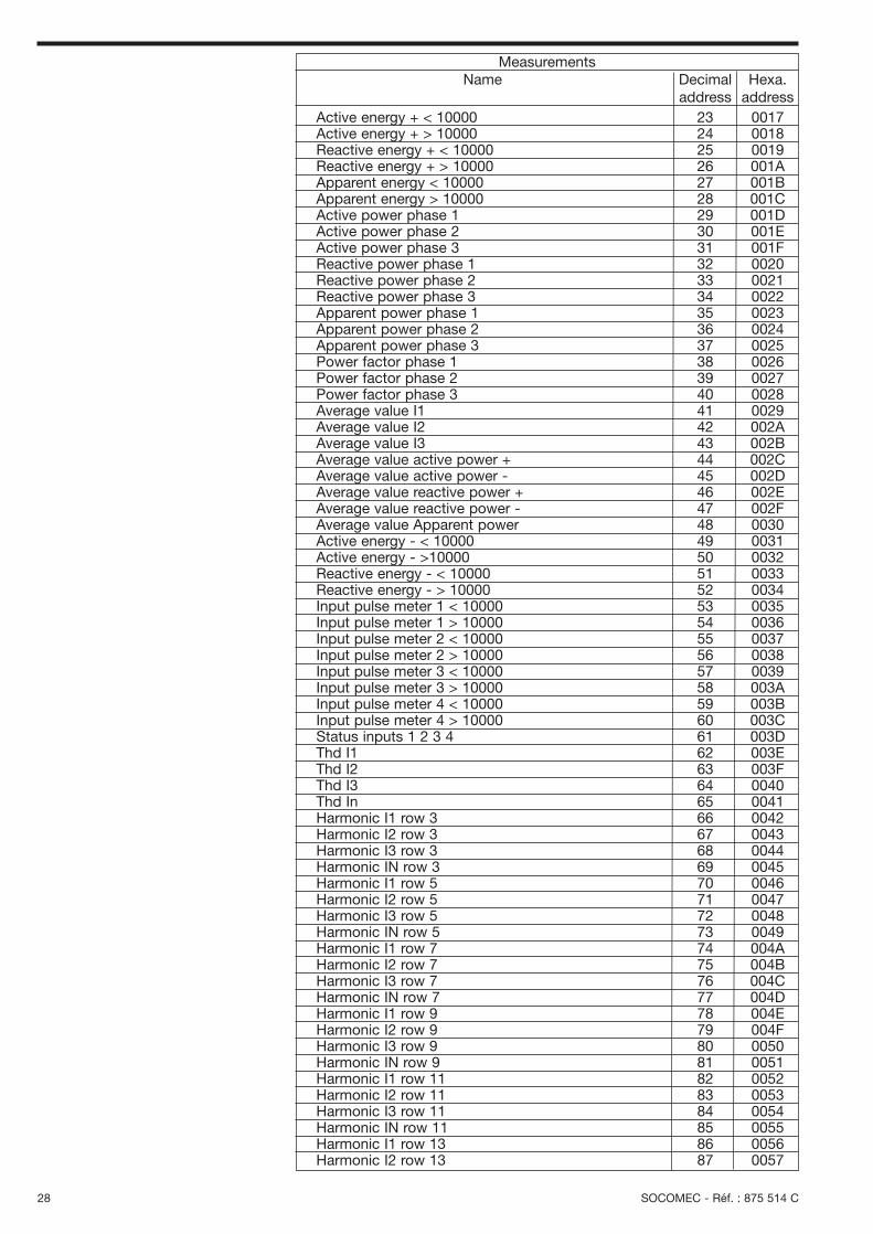
List of value addresses
Frame number 1Address of value 1 2Address of value 2 2Address of value 3 2Address of value 4 2
Description Size (bytes)
Output frame
MODULE 10 : RESERVED FOR MANUFACTURER10
MODULE 11 : SIZE LIMITED SPECIAL FRAME11
This module allows the creation of a personalised module of 4 values.
Length: 9 bytes
NB:The frame number is an identificationnumber. It is used to check if the answercoming from the slave device corresponds to the PLC’s request.The list of values is available p. 27, 28and 29.
28 SOCOMEC - Réf. : 875 514 C
Active energy + < 10000 23 0017Active energy + > 10000 24 0018Reactive energy + < 10000 25 0019Reactive energy + > 10000 26 001AApparent energy < 10000 27 001BApparent energy > 10000 28 001CActive power phase 1 29 001DActive power phase 2 30 001EActive power phase 3 31 001FReactive power phase 1 32 0020Reactive power phase 2 33 0021Reactive power phase 3 34 0022Apparent power phase 1 35 0023Apparent power phase 2 36 0024Apparent power phase 3 37 0025Power factor phase 1 38 0026Power factor phase 2 39 0027Power factor phase 3 40 0028Average value I1 41 0029Average value I2 42 002AAverage value I3 43 002BAverage value active power + 44 002CAverage value active power - 45 002DAverage value reactive power + 46 002EAverage value reactive power - 47 002FAverage value Apparent power 48 0030Active energy - < 10000 49 0031Active energy - >10000 50 0032Reactive energy - < 10000 51 0033Reactive energy - > 10000 52 0034Input pulse meter 1 < 10000 53 0035Input pulse meter 1 > 10000 54 0036Input pulse meter 2 < 10000 55 0037Input pulse meter 2 > 10000 56 0038Input pulse meter 3 < 10000 57 0039Input pulse meter 3 > 10000 58 003AInput pulse meter 4 < 10000 59 003BInput pulse meter 4 > 10000 60 003CStatus inputs 1 2 3 4 61 003DThd I1 62 003EThd I2 63 003FThd I3 64 0040Thd In 65 0041Harmonic I1 row 3 66 0042Harmonic I2 row 3 67 0043Harmonic I3 row 3 68 0044Harmonic IN row 3 69 0045Harmonic I1 row 5 70 0046Harmonic I2 row 5 71 0047Harmonic I3 row 5 72 0048Harmonic IN row 5 73 0049Harmonic I1 row 7 74 004AHarmonic I2 row 7 75 004BHarmonic I3 row 7 76 004CHarmonic IN row 7 77 004DHarmonic I1 row 9 78 004EHarmonic I2 row 9 79 004FHarmonic I3 row 9 80 0050Harmonic IN row 9 81 0051Harmonic I1 row 11 82 0052Harmonic I2 row 11 83 0053Harmonic I3 row 11 84 0054Harmonic IN row 11 85 0055Harmonic I1 row 13 86 0056Harmonic I2 row 13 87 0057
MeasurementsName Decimal Hexa.
address address
SOCOMEC - Réf. : 875 514 D 29
EN
GLIS
H
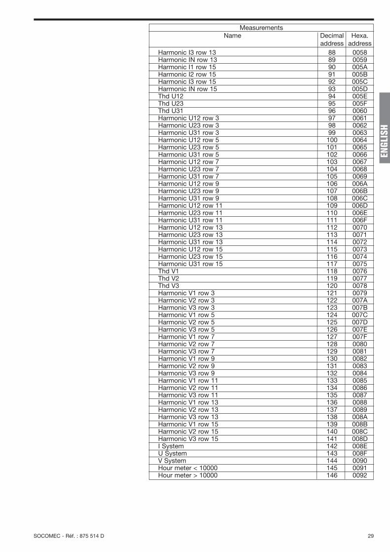
Harmonic I3 row 13 88 0058Harmonic IN row 13 89 0059Harmonic I1 row 15 90 005AHarmonic I2 row 15 91 005BHarmonic I3 row 15 92 005CHarmonic IN row 15 93 005DThd U12 94 005EThd U23 95 005FThd U31 96 0060Harmonic U12 row 3 97 0061Harmonic U23 row 3 98 0062Harmonic U31 row 3 99 0063Harmonic U12 row 5 100 0064Harmonic U23 row 5 101 0065Harmonic U31 row 5 102 0066Harmonic U12 row 7 103 0067Harmonic U23 row 7 104 0068Harmonic U31 row 7 105 0069Harmonic U12 row 9 106 006AHarmonic U23 row 9 107 006BHarmonic U31 row 9 108 006CHarmonic U12 row 11 109 006DHarmonic U23 row 11 110 006EHarmonic U31 row 11 111 006FHarmonic U12 row 13 112 0070Harmonic U23 row 13 113 0071Harmonic U31 row 13 114 0072Harmonic U12 row 15 115 0073Harmonic U23 row 15 116 0074Harmonic U31 row 15 117 0075Thd V1 118 0076Thd V2 119 0077Thd V3 120 0078Harmonic V1 row 3 121 0079Harmonic V2 row 3 122 007AHarmonic V3 row 3 123 007BHarmonic V1 row 5 124 007CHarmonic V2 row 5 125 007DHarmonic V3 row 5 126 007EHarmonic V1 row 7 127 007FHarmonic V2 row 7 128 0080Harmonic V3 row 7 129 0081Harmonic V1 row 9 130 0082Harmonic V2 row 9 131 0083Harmonic V3 row 9 132 0084Harmonic V1 row 11 133 0085Harmonic V2 row 11 134 0086Harmonic V3 row 11 135 0087Harmonic V1 row 13 136 0088Harmonic V2 row 13 137 0089Harmonic V3 row 13 138 008AHarmonic V1 row 15 139 008BHarmonic V2 row 15 140 008CHarmonic V3 row 15 141 008DI System 142 008EU System 143 008FV System 144 0090Hour meter < 10000 145 0091Hour meter > 10000 146 0092
MeasurementsName Decimal Hexa.
address address

30 SOCOMEC - Réf. : 875 514 C
DIAGNOSTICSThese contain an indication of the presence of DIRIS option modules, the serial number, the Diris Ap product codeand the presence of an alarm or an excess.
Option present on slot 1 10: RS4851: Metering3: HarmonicsF0: In20: 2 In /2 out30: 2 0 /4 - 20 mA50: PROFIBUS®-DPOption present on slot 2 10: RS4851: Metering3: HarmonicsF0: In20: 2 In /2 out30: 2 0 /4 - 20 mA50: PROFIBUS®-DPOption present on slot 3 10: RS4851: Metering3: HarmonicsF0: In20: 2 In /2 out30: 2 0 /4 - 20 mA50: PROFIBUS®-DPOption present on slot 4 10: RS4851: Metering3: HarmonicsF0: In20: 2 In /2 out30: 2 0 /4 - 20 mA50: PROFIBUS®-DPSerial number 4Product code 1Alarms 4bit 0: Alarm Ibit 1: Alarm Inbit 2: Alarm Ubit 3: Alarm Vbit 4: Alarm P+bit 5: Alarm Q+bit 6: Alarm Sbit 7: Alarm Fbit 8: Alarm PFL
Description Size (bytes)
Slot
1
Slot
2
Slot
3
Slot
4
DIR
IS 4
75 A
Frame number 1Value 1 2Value 2 2Value 3 2Value 4 2
Description Size (bytes)
Input frame
SOCOMEC - Réf. : 875 514 D 31
EN
GLIS
H
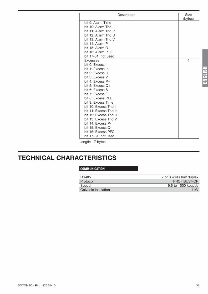
TECHNICAL CHARACTERISTICS
RS485 2 or 3 wires half duplexProtocol PROFIBUS®-DPSpeed 9.6 to 1500 kbaudsGalvanic insulation 4 kV
COMMUNICATION
bit 9: Alarm Timebit 10: Alarm Thd Ibit 11: Alarm Thd Inbit 12: Alarm Thd Ubit 13: Alarm Thd Vbit 14: Alarm P-bit 15: Alarm Q-bit 16: Alarm PFCbit 17-31: not usedExcesses 4bit 0: Excess Ibit 1: Excess Inbit 2: Excess Ubit 3: Excess Vbit 4: Excess P+bit 5: Excess Q+bit 6: Excess Sbit 7: Excess Fbit 8: Excess PFLbit 9: Excess Timebit 10: Excess Thd Ibit 11: Excess Thd Inbit 12: Excess Thd Ubit 13: Excess Thd Vbit 14: Excess P-bit 15: Excess Q-bit 16: Excess PFCbit 17-31: not used
Description Size (bytes)
Length: 17 bytes

SOCOMEC - Ref. : 875 814 D - 10/03
DIR
IS 3
45B
- D
IRIS
458
A
HEAD OFFICE
SOCOMEC GROUPSwitchgear and UPSS.A. capital de 11 052 200 €R.C. Strasbourg 5484500 149 B
SOCOMEC 1, rue de Westhouse - B.P. 10F-67235 Benfeld Cedex-FRANCETel. +33 (0)3 88 57 41 41 - Fax +33 (0)3 88 57 78 78
SOCOMEC95, rue Pierre GrangeF-94132 Fontenay-sous-Bois Cedex-FRANCETel. +33 (0)1 45 14 63 40 - Fax +33 (0)1 48 77 31 [email protected]
SALES MANAGEMENT DIVISIONIndustrial Switching & Protection Systems
This document is not contractual. SOCOMEC reserves the right tomodify features without prior notice in view of continued improvements.
www.socomec.com


![PROFIBUS DP bus interface, PROFIBUS DP [BU 2700]...Sicherheit/PROFIBUS DP [BU 2700]/Bestimmungsgemäße Ver wendung PROFIBUS DP @ 8\mod_1461835577600_388.docx @ 2249429 @ 2 @ 1 2.1](https://static.fdocuments.in/doc/165x107/60b54c574bd00c04b50e633d/profibus-dp-bus-interface-profibus-dp-bu-2700-sicherheitprofibus-dp-bu.jpg)