Enhancing surface integrity by high-speed extrusion machining
10
ORIGINAL ARTICLE Enhancing surface integrity by high-speed extrusion machining Yao Liu 1 & Songlin Cai 2 & Xinchun Shang 1 & Lanhong Dai 3 Received: 29 December 2015 /Accepted: 25 July 2016 /Published online: 8 August 2016 # Springer-Verlag London 2016 Abstract High-speed machining (HSM) is an advanced ma- chining technology to form components. However, the poor surface integrity tends to appear due to chip flow instability in HSM. It is found that the surface integrity results from the competition of shear deformation instability between in pri- mary shear zone (PSZ) and in separating shear zone (SSZ). To improve the surface integrity of machined components, the systematic high-speed extrusion machining (HSEM) experi- ments of magnesium alloy AZ31B with different constraint extrusion factors (CEFs) were carried out. The instability of shear deformation in PSZ is suppressed, and the microwaves on machined surface disappear when CEF is equal to or larger than a certain value. The measurements of the machined sur- face show that an improvement of surface integrity is achieved if CEF exceeds a certain value. The theoretical model for HSEM was established to elucidate the critical CEF. The un- derlying physics of surface integrity in HSEM is further re- vealed. The experimental results verify the validity of the the- oretical model. Keywords High-speed extrusion machining . Surface integrity . Characteristic instability time . Chip morphology transition 1 Introduction Machining operation is a versatile manufacturing process in terms of its capability to obtain designed geometrical dimen- sions by removing unwanted materials from a workpiece [1]. High-speed machining (HSM) has become an important de- velopment area in advanced manufacturing technology due to the growing demand for enhanced manufacturing efficiency [2–4]. However, the continuous chip flow breaks down and serrated chips begin to form with the increasing cutting speed [5, 6]. The chip morphology transition from continuous to serrated chips leads to the intense cutting force fluctuation [7–10], which is generally believed harmful for the cutting tool and surface integrity [11–14]. Therefore, the serrated chips should be suppressed in order to improve the surface integrity of machined components during HSM. The mechanism of serrated chip has been extensively stud- ied in the past decades. For most ductile metallic materials, the occurrence of serrated chip flow is related to the thermo- plastic shear instability within primary shear zone (PSZ) [15, 16]. Considerable researches on the shear localization in PSZ have been carried out. Several classic investigations have been performed to study the onset of serrated chip flow. Recht first put forward that the serrated chips emerged in HSM if the strain hardening of materials was overtaken by the thermal softening effect within PSZ [17]. A similar approach, where the shear stress achieves a maximum in the shear stress-shear strain curve, was proposed to explain the transition from con- tinuous to serrated chips [18]. Komanduri and Hou extended Recht’ s classical model to predict the onset of shear instability, * Songlin Cai [email protected] * Lanhong Dai [email protected] 1 School of Mathematics and Physics, University of Science and Technology Beijing, Beijing 100083, People’ s Republic of China 2 China Electric Power Research Institute, State Grid Corporation of China, Beijing 100192, People’ s Republic of China 3 State Key Laboratory of Nonlinear Mechanics, Institute of Mechanics, Chinese Academy of Sciences, Beijing 100190, People’ s Republic of China Int J Adv Manuf Technol (2017) 89:2141–2150 DOI 10.1007/s00170-016-9252-6
Transcript of Enhancing surface integrity by high-speed extrusion machining

ORIGINAL ARTICLE
Enhancing surface integrity by high-speed extrusion machining
Yao Liu1& Songlin Cai2 & Xinchun Shang1
& Lanhong Dai3
Received: 29 December 2015 /Accepted: 25 July 2016 /Published online: 8 August 2016# Springer-Verlag London 2016
Abstract High-speed machining (HSM) is an advanced ma-chining technology to form components. However, the poorsurface integrity tends to appear due to chip flow instability inHSM. It is found that the surface integrity results from thecompetition of shear deformation instability between in pri-mary shear zone (PSZ) and in separating shear zone (SSZ). Toimprove the surface integrity of machined components, thesystematic high-speed extrusion machining (HSEM) experi-ments of magnesium alloy AZ31B with different constraintextrusion factors (CEFs) were carried out. The instability ofshear deformation in PSZ is suppressed, and the microwaveson machined surface disappear when CEF is equal to or largerthan a certain value. The measurements of the machined sur-face show that an improvement of surface integrity is achievedif CEF exceeds a certain value. The theoretical model forHSEM was established to elucidate the critical CEF. The un-derlying physics of surface integrity in HSEM is further re-vealed. The experimental results verify the validity of the the-oretical model.
Keywords High-speed extrusionmachining . Surfaceintegrity . Characteristic instability time . Chip morphologytransition
1 Introduction
Machining operation is a versatile manufacturing process interms of its capability to obtain designed geometrical dimen-sions by removing unwanted materials from a workpiece [1].High-speed machining (HSM) has become an important de-velopment area in advanced manufacturing technology due tothe growing demand for enhanced manufacturing efficiency[2–4]. However, the continuous chip flow breaks down andserrated chips begin to form with the increasing cutting speed[5, 6]. The chip morphology transition from continuous toserrated chips leads to the intense cutting force fluctuation[7–10], which is generally believed harmful for the cuttingtool and surface integrity [11–14]. Therefore, the serratedchips should be suppressed in order to improve the surfaceintegrity of machined components during HSM.
The mechanism of serrated chip has been extensively stud-ied in the past decades. For most ductile metallic materials, theoccurrence of serrated chip flow is related to the thermo-plastic shear instability within primary shear zone (PSZ) [15,16]. Considerable researches on the shear localization in PSZhave been carried out. Several classic investigations have beenperformed to study the onset of serrated chip flow. Recht firstput forward that the serrated chips emerged in HSM if thestrain hardening of materials was overtaken by the thermalsoftening effect within PSZ [17]. A similar approach, wherethe shear stress achieves a maximum in the shear stress-shearstrain curve, was proposed to explain the transition from con-tinuous to serrated chips [18]. Komanduri and Hou extendedRecht’s classical model to predict the onset of shear instability,
* Songlin [email protected]
* Lanhong [email protected]
1 School of Mathematics and Physics, University of Science andTechnology Beijing, Beijing 100083, People’s Republic of China
2 China Electric Power Research Institute, State Grid Corporation ofChina, Beijing 100192, People’s Republic of China
3 State Key Laboratory of Nonlinear Mechanics, Institute ofMechanics, Chinese Academy of Sciences, Beijing 100190, People’sRepublic of China
Int J Adv Manuf Technol (2017) 89:2141–2150DOI 10.1007/s00170-016-9252-6
where shear localization is imminent if the shear stress in shearband is less than or equal to the shear strength of bulk mate-rials [19]. Semiatin and Rao first derived the quantitative crit-ical speed for the transition from continuous to serrated chips[20]. Xie et al. showed the influence of cutting conditions onshear localization in HSM [21]. Considering the coupling sys-tem of tool-chip workpiece, Burns and Davies explained theemergence of serrated chips as a supercritical Hopf bifurcationphenomenon [22]. Aifantis et al. added the effect of straingradient into the governing equation of PSZ and carried outthe perturbation analysis of the governing equation to predictthe onset of serrated chip flow [23]. Also, by using perturba-tion analysis, some other adiabatic shear instability criticalconditions were built by considering some specific effects inHSM [24]. Recently, based on dimensional analysis and nu-merical simulations, Ye et al. derived an explicit expression ofthe critical cutting speed in terms of material properties, uncutchip thickness, and tool rake angle [25].
The fantastic pioneer works are concerned about the for-mation of serrated chips in HSM. The studies have demon-strated that the state of stress in PSZ has a significant effect onthe chip formation in HSM. Actually, for low-speed machin-ing (LSM), Chiffre put forward extrusion cutting to imposethe extrusion stress in PSZ for controlling the chip formationprocess [26]. Chandrasekar and co-workers further devised alarge-strain extrusion machining (LSEM) apparatus to fabri-cate ultrafine grain materials (UFGs) at a low cutting speed[27]. Recently, inspired by the works of Chiffre andChandrasekar, Dai et al. developed a high-speed extrusionmachining (HSEM) device to research the effect of constrainton the chip formation during HSM [28]. They stated that thechip morphology transforms from serrated to continuous chipsonce the constraint extrusion factor is equal to or greater than acertain value [29]. Previous work by the authors showed thatconstraint extrusion level affected the microstructure of chipsduring HSEM [30]; however, the research about the effect ofextrusion on surface integrity in HSEM is vacant. In this pa-per, systematic HSEM experiments of magnesium alloy werecarried out to explore the effect of extrusion on surface integ-rity. The experimental results show that an improvementof surface integrity is achieved when the constraint ex-trusion factor (CEF) is equal to or larger than a certainvalue. The theoretical model for HSEM is established toelucidate the critical CEF. The underlying physics ofsurface integrity in HSEM is clearly revealed by com-bining the experimental result with theoretical model.
2 Experimental procedure
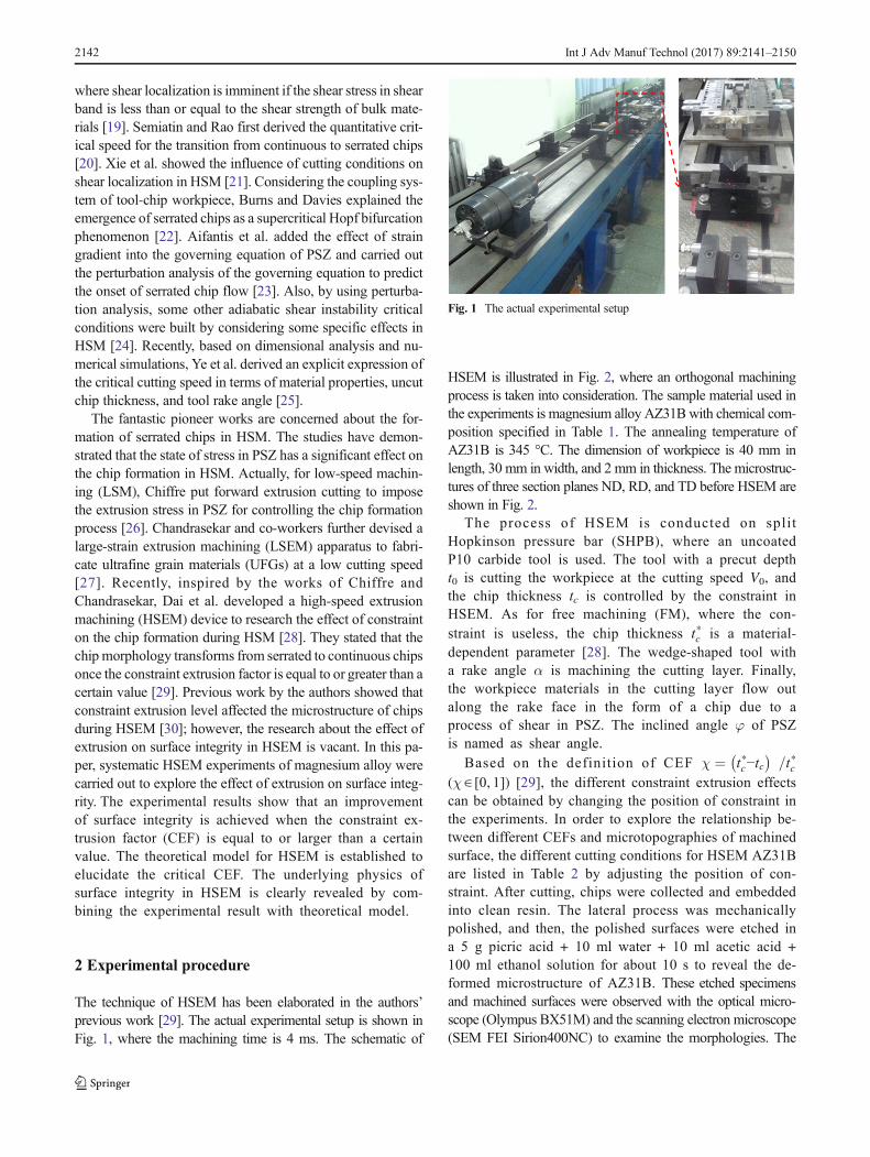
The technique of HSEM has been elaborated in the authors’previous work [29]. The actual experimental setup is shown inFig. 1, where the machining time is 4 ms. The schematic of
HSEM is illustrated in Fig. 2, where an orthogonal machiningprocess is taken into consideration. The sample material used inthe experiments is magnesium alloy AZ31Bwith chemical com-position specified in Table 1. The annealing temperature ofAZ31B is 345 °C. The dimension of workpiece is 40 mm inlength, 30 mm in width, and 2 mm in thickness. The microstruc-tures of three section planes ND, RD, and TD before HSEM areshown in Fig. 2.
The process of HSEM is conducted on splitHopkinson pressure bar (SHPB), where an uncoatedP10 carbide tool is used. The tool with a precut deptht0 is cutting the workpiece at the cutting speed V0, andthe chip thickness tc is controlled by the constraint inHSEM. As for free machining (FM), where the con-straint is useless, the chip thickness t*c is a material-dependent parameter [28]. The wedge-shaped tool witha rake angle α is machining the cutting layer. Finally,the workpiece materials in the cutting layer flow outalong the rake face in the form of a chip due to aprocess of shear in PSZ. The inclined angle φ of PSZis named as shear angle.
Based on the definition of CEF χ ¼ t*c−tc� �
=t*c(χ∈ [0, 1]) [29], the different constraint extrusion effectscan be obtained by changing the position of constraint inthe experiments. In order to explore the relationship be-tween different CEFs and microtopographies of machinedsurface, the different cutting conditions for HSEM AZ31Bare listed in Table 2 by adjusting the position of con-straint. After cutting, chips were collected and embeddedinto clean resin. The lateral process was mechanicallypolished, and then, the polished surfaces were etched ina 5 g picric acid + 10 ml water + 10 ml acetic acid +100 ml ethanol solution for about 10 s to reveal the de-formed microstructure of AZ31B. These etched specimensand machined surfaces were observed with the optical micro-scope (Olympus BX51M) and the scanning electron microscope(SEM FEI Sirion400NC) to examine the morphologies. The
Fig. 1 The actual experimental setup
2142 Int J Adv Manuf Technol (2017) 89:2141–2150

machined surfaces were further characterized by means of aContourGT-K 3D profiler.
3 Experimental observations
Figure 3 shows the microstructure of chips for differentCEFs in HSEM AZ31B. The transition of chip morphol-ogy from serrated to continuous is observed with theincreasing CEF. As for FM (Fig. 3a), the chips areserrated due to the absence of extrusion constraint andthe shear bands are obviously observed between thesaw-teeth like chips. However, in the condition ofHSEM, the constraint has an effect on the chip mor-phology and the serrations are suppressed by the con-straint (Fig. 3b). When CEF reaches or exceeds a crit-ical value, i.e., χ= 0.56, the thermo-plastic shear insta-bility is totally suppressed, which leads to the disap-pearance of shear bands in chips (see Fig. 3c, d). Inthis case, homogeneous plastic deformation is realizedin chips and the refined grain distributes in chipsuniformly.
The occurrence of serrated chips leads to the cuttingforce fluctuation, decreased tool life, degradation of thesurface finish, and less accuracy in machine parts duringHSM. According to the experimental observations inFig. 3, the technique of HSEM is successful to achievethe transition of chip morphology from serrated to con-tinuous. The micro-topography of machined surface isfurther examined to research the effect of constraint lev-el on the surface integrity in HSEM. As illustrated in
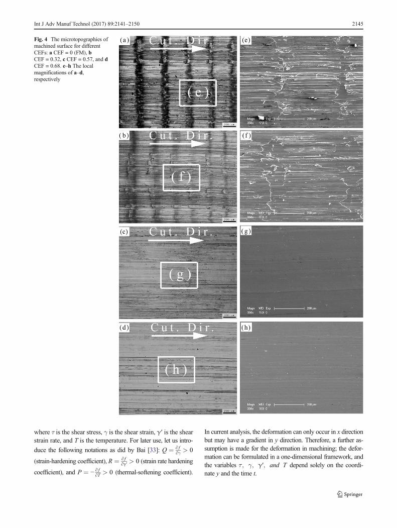
Fig. 4a, the periodic microwaves distribute on the ma-chined surface uniformly for FM, as numerically pre-dicted by Mabrouki et al. [31]. For the small CEF inHSEM, i.e., χ = 0.32, the periodic microwaves stillemerge on the machined surface (Fig. 4b) because theserrated chips are not completely suppressed by con-straint at the present constraint level (see Fig. 3b).When CEF is equal to or larger than a critical value,i.e., χ= 0.56, there are no periodic microwaves on themachined surface (Fig. 4c, d).
The surface integrity was further analyzed by meansof a ContourGT-K 3D profiler. The digitalized scannedsurfaces are shown in Fig. 5. The profiles of the ma-chined surfaces are presented in Fig. 6 via softwaremaking a cross section of digital scanned surfaces, par-allel to the cutting direction. According to the profilesof the machined surfaces in Fig. 6, the CEF inducessignificant variations in terms of surface integrity. Thegrooves are shallower with the increasing CEF, whichresults in a better surface integrity in HSEM. The sur-face roughness Ra was measured by means of a TaylorHobson Surtronic 25R portable roughness tester, whichis shown in Fig. 6. With the increasing CEF in HSEM,the surface roughness is smaller and a better surfaceintegrity is achieved (see Figs. 5 and 6).
Fig. 2 Schematic of high-speedextrusion machining (HSEM) andmicrostructures of three sectionplanes ND, RD, and TD in thesample
Table 2 Cutting condition in HSEM AZ31B
Cutting parameters Notation Value
Rake angle α 0°
Clearance angle α2 5°
Tool edge radius rT 10 μm
Precut chip thickness t0 200 μm
Cutting speed V0 10 m/s
Controlled chip thickness tc 280, 190, 120, and 90 μm
Constraint extrusion factor χ 0, 0.32, 0.57, and 0.68
Table 1 Chemical composition of the magnesium alloy AZ31B
Elements Mg Al Zn Mn Si Cu Ca Others
Weight percent 97 2.5–3.5 0.6–1.4 0.2 0.1 0.05 0.04 ≤0.01
Int J Adv Manuf Technol (2017) 89:2141–2150 2143

4 Theoretical modeling for HSEM
4.1 The governing equations
As shown in the experimental results, an improvementof surface integrity can be achieved if CEF is equal toor larger than a certain value in HSEM. The theoreticalmodel for HSEM is established here to elucidate thecritical CEF. Figure 7 shows a schematic of theHSEM, where the wedge-shaped tool with a rake angleα is cutting the workpiece at the cutting speed V0. Thematerials in the cutting layer are sheared in PSZ andthen flow out along the rake face in the form of a chip.The materials in separating shear zone (SSZ) are sepa-rated from the workpiece by shear deformation withinSSZ. The width of SSZ d is about t0/10 based on ex-perimental observations [32]. The shear deformation inPSZ and that in SSZ occur simultaneously duringHSEM, which leads to the following two characteristicinstability times: the characteristic instability time of tpin PSZ and that of ts in SSZ. If tp> ts, the instability ofshear deformation in SSZ is before that in PSZ. Theseparation of materials in SSZ is ahead of the serrationin PSZ. If tp< ts, the instability of shear deformation inSSZ is after that in PSZ. The materials in SSZ are notseparated from the workpiece when the serration formsin PSZ, which results in a poor machined surface.
As for the characteristic instability time tp in PSZ,the theoretical model for tp put forward by Cai and
Dai [29] is used here. The spectral equation controllingthe shear deformation in PSZ is the following form[29]:
8α3
p þ 8S1α2
p þ 2 S21−S2� �
αp þ S1S2−S3 ¼ 0: ð1Þ
In Eq. (1), αp is the dimensionless growth rate, and thedimensionless polynomial coefficients are defined by
S1 ¼ 1þ Að Þk2
p þ N þ C
S2 ¼ Ak4
p þ 1þ N−Bð Þk2
pþM þ CN
S3 ¼ k4
p þMk2
pþMC;
8>>>>>>><>>>>>>>:
ð2Þ
where kp is the dimensionless wave number and A , B , C ,M , and N are the dimensionless numbers which are illustrat-ed in the work [29]. The maximum (αpm ) of αp can be ob-tained by solving Eqs. (1) and (2). Then, the characteristicinstability time tp in PSZ is given by tp ¼ 1=αpm.
In order to achieve the characteristic instability time ts inSSZ, an Eulerian coordinate system (xoy) is attached to thetool with x axis parallel to the direction of cutting speed and yaxis normal to that direction, respectively (Fig. 7). The work-piece is considered to be thermo-viscoplastic material, and itsconstitutive equation is given by
τ ¼ f γ;γ′; T ;ð Þ ð3Þ
Fig. 3 The microstructures of chips for different CEFs in HSEM AZ31B: a CEF = 0 (FM), b CEF = 0.32, c CEF = 0.57, and d CEF = 0.68
2144 Int J Adv Manuf Technol (2017) 89:2141–2150
where τ is the shear stress, γ is the shear strain, γ′ is the shearstrain rate, and T is the temperature. For later use, let us intro-
duce the following notations as did by Bai [33]: Q ¼ ∂ f∂γ > 0
(strain-hardening coefficient), R ¼ ∂ f∂γ′ > 0 (strain rate hardening
coefficient), and P ¼ − ∂ f∂T > 0 (thermal-softening coefficient).
In current analysis, the deformation can only occur in x directionbut may have a gradient in y direction. Therefore, a further as-sumption is made for the deformation in machining; the defor-mation can be formulated in a one-dimensional framework, andthe variables τ ; γ; γ′; and T depend solely on the coordi-nate y and the time t.
Fig. 4 The microtopographies ofmachined surface for differentCEFs: a CEF = 0 (FM), bCEF = 0.32, c CEF = 0.57, and dCEF = 0.68. e–h The localmagnifications of a–d,respectively
Int J Adv Manuf Technol (2017) 89:2141–2150 2145

The momentum is conserved in SSZ, so the momen-tum equation is given by
∂2τ∂y2
¼ ρ∂γ′∂t
; ð4Þ
where ρ is the density of materials.
The conservation equation of energy in SSZ is written by
∂T∂t
¼ βτγ′ρc
þ kρc
Th−Td2
; ð5Þ
where T is the temperature in SSZ, Th is the tempera-ture around SSZ, and d is the thickness of SSZ. In
Fig. 5 The digitalized scanned surfaces for different CEFs: a CEF = 0 (FM), b CEF = 0.32, c CEF = 0.57, and d CEF = 0.68
Fig. 6 The profiles of themachined surfaces for differentCEFs: a CEF = 0 (FM), bCEF = 0.32, c CEF = 0.57, and dCEF = 0.68
2146 Int J Adv Manuf Technol (2017) 89:2141–2150
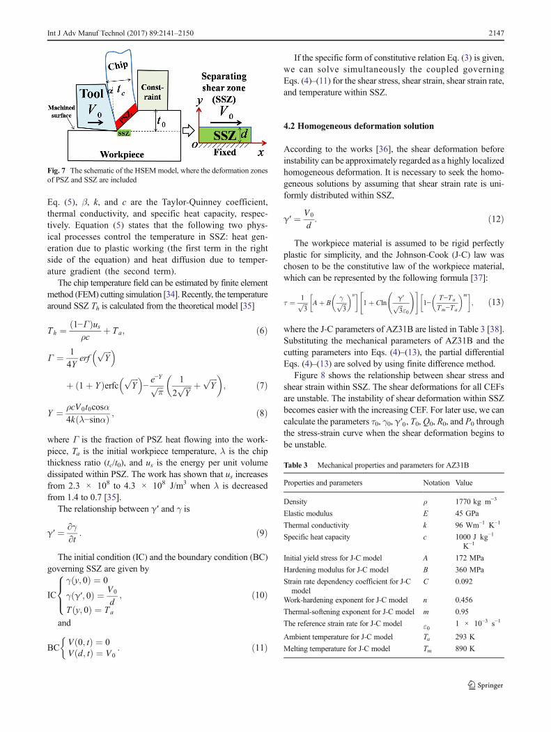
Eq. (5), β, k, and c are the Taylor-Quinney coefficient,thermal conductivity, and specific heat capacity, respec-tively. Equation (5) states that the following two phys-ical processes control the temperature in SSZ: heat gen-eration due to plastic working (the first term in the rightside of the equation) and heat diffusion due to temper-ature gradient (the second term).
The chip temperature field can be estimated by finite elementmethod (FEM) cutting simulation [34]. Recently, the temperaturearound SSZ Th is calculated from the theoretical model [35]
Th ¼ 1−Γð Þusρc
þ Ta; ð6Þ
Γ ¼ 1
4Yerf
ffiffiffiffiY
p� �
þ 1þ Yð ÞerfcffiffiffiffiY
p� �−e−Yffiffiffiπ
p 1
2ffiffiffiffiY
p þffiffiffiffiY
p� �; ð7Þ
Y ¼ ρcV0t0cosα4k λ−sinαð Þ ; ð8Þ
where Γ is the fraction of PSZ heat flowing into the work-piece, Ta is the initial workpiece temperature, λ is the chipthickness ratio (tc/t0), and us is the energy per unit volumedissipated within PSZ. The work has shown that us increasesfrom 2.3 × 10⁸ to 4.3 × 10⁸ J/m3 when λ is decreasedfrom 1.4 to 0.7 [35].
The relationship between γ′ and γ is
γ′ ¼ ∂γ∂t
: ð9Þ
The initial condition (IC) and the boundary condition (BC)governing SSZ are given by
IC
γ y; 0ð Þ ¼ 0
γ γ′; 0ð Þ ¼ V0
dT y; 0ð Þ ¼ Ta
8><>: ; ð10Þ
and
BCV 0; tð Þ ¼ 0V d; tð Þ ¼ V0
: ð11Þ
If the specific form of constitutive relation Eq. (3) is given,we can solve simultaneously the coupled governingEqs. (4)–(11) for the shear stress, shear strain, shear strain rate,and temperature within SSZ.
4.2 Homogeneous deformation solution
According to the works [36], the shear deformation beforeinstability can be approximately regarded as a highly localizedhomogeneous deformation. It is necessary to seek the homo-geneous solutions by assuming that shear strain rate is uni-formly distributed within SSZ,
γ′ ¼ V0
d: ð12Þ
The workpiece material is assumed to be rigid perfectlyplastic for simplicity, and the Johnson-Cook (J-C) law waschosen to be the constitutive law of the workpiece material,which can be represented by the following formula [37]:
τ ¼ 1ffiffiffi3
p Aþ Bγffiffiffi3
p� �n �
1þ Clnγ′ffiffiffi3
pε0
!" #1−
T−Ta
Tm−Ta
� �m �; ð13Þ
where the J-C parameters of AZ31B are listed in Table 3 [38].Substituting the mechanical parameters of AZ31B and thecutting parameters into Eqs. (4)–(13), the partial differentialEqs. (4)–(13) are solved by using finite difference method.
Figure 8 shows the relationship between shear stress andshear strain within SSZ. The shear deformations for all CEFsare unstable. The instability of shear deformation within SSZbecomes easier with the increasing CEF. For later use, we cancalculate the parameters τ0, γ0, γ′0, T0,Q0, R0, and P0 throughthe stress-strain curve when the shear deformation begins tobe unstable.
Fig. 7 The schematic of the HSEMmodel, where the deformation zonesof PSZ and SSZ are included
Table 3 Mechanical properties and parameters for AZ31B
Properties and parameters Notation Value
Density ρ 1770 kg m−3
Elastic modulus E 45 GPa
Thermal conductivity k 96 Wm−1 K−1
Specific heat capacity c 1000 J kg−1
K−1
Initial yield stress for J-C model A 172 MPa
Hardening modulus for J-C model B 360 MPa
Strain rate dependency coefficient for J-Cmodel
C 0.092
Work-hardening exponent for J-C model n 0.456
Thermal-softening exponent for J-C model m 0.95
The reference strain rate for J-C model ε0 1 × 10⁻³ s−1
Ambient temperature for J-C model Ta 293 K
Melting temperature for J-C model Tm 890 K
Int J Adv Manuf Technol (2017) 89:2141–2150 2147

4.3 Characteristic instability time within SSZ
The physical shear localization can be related to the mathe-matical instability in the differential equations governing thedeformation within SSZ. According to the dealing method[33], the stability analysis is simplified by seeking an inhomo-geneous deformation solution with respect to small perturba-tions on the homogeneous solution. Such that
τγγ′T
2664
3775 ¼
τ0γ0γ′0T0
2664
3775þ
τ*γ*γ′*T*
2664
3775exp pt þ iqyð Þ; ð14Þ
where τ γ γ′ T½ � are the inhomogeneous solutions ofEqs. (3)–(11), τ0 γ0 γ′0 T0½ � are the homogeneous solu-tions, τ* γ* γ′* T*½ � are the small constants characterizingthe magnitude of the perturbation, q is the wave number, and pis the growth rate. Substituting Eq. (14) into Eqs. (3)–(5) and(9), considering terms of first order in the perturbation mag-nitude leads to the following spectral equation:
ρp3 þ βP0γ′0c
þ k
cd2þ q2R0
� �p2
þ kR0
ρcd2þ Q0−
βP0τ0ρc
� �q2pþ kQ0
ρcd2q2
¼ 0: ð15Þ
The dimensionless variables are introduced here,
αs ¼ kpcQ0
; k2
s¼ k2q2
ρc2Q0;A ¼ cR0
k;B ¼ βP0τ0
ρcQ0;C ¼ βkP0γ′0
ρc2Q0;D ¼ k2
ρc2d2Q0
�;
ð16Þ
and then, Eq. (15) becomes the following form:
α3
s þ Ak2
s þ C þ D� �
α2
s þ 1þ AD−Bð Þk2
sαs þ Dk2
s
¼ 0: ð17Þ
The maximum (αsm ) of αs can be achieved by varying k2sfrom 0 to +∞ in Eq. (17), and then, the characteristic instabilitytime within SSZ ts is obtained by ts ¼ 1=αsm.
Deborah number was initially proposed by Reiner to de-scribe the rheological behavior of materials [39]. Recently,Deborah number was also used for characterizing shear defor-mation instability of materials [40, 41]. Here, we define theeffective Deborah number De as follows:
De ¼ tstp: ð18Þ
It is obvious that this Deborah number can characterize thecompetition between SSZ and PSZ. If De < 1, the materials
within SSZ tend to have fluid-like behavior; i.e., the sheardeformation instability in SSZ is faster than that in PSZ. ForDe > 1, the materials within SSZ are prone to have solid-like behavior; i.e., the shear deformation instability in PSZ isfaster than that in SSZ.
Using the homogeneous deformation solution in Fig. 8, thevariation of De with CEF is illustrated in Fig. 9. The poor andgood surface integrity are separated by a specific constraintextrusion factor 0.5. If CEF is smaller than 0.5, De is morethan 1. Compared with the materials in PSZ, the materialswithin SSZ are more like solids. The instability of shear de-formation in PSZ is before that in SSZ. The materials in SSZare not separated completely from the workpiece during theformation of serration in PSZ, which results in a poor surfaceintegrity. If CEF is larger than 0.5, De is less than 1. Theinstability of shear deformation in PSZ is after that in SSZ.The materials in SSZ are separated completely from the work-piece before the shear instability in PSZ, and an improvementof surface integrity is achieved. The deformation behaviors
Fig. 8 The calculated stress-strain relations within SSZ for differentCEFs
Fig. 9 Comparison of theoretical model with experimental observationsfor different CEFs
2148 Int J Adv Manuf Technol (2017) 89:2141–2150

predicted by the theoretical model are identical to the experi-mental results (Fig. 9). Therefore, the present model is valid toelucidate the critical CEF, which indicates the improvement ofsurface integrity.
In order to further reveal the effect of constraint on surfaceintegrity, the relationships between Deborah number and cut-ting speed for different CEFs are calculated by substituting thecharacteristic instability times into Eq. (18), which are illus-trated in Fig. 10. The Deborah number decreases with theincreasing cutting speed, which means that the shear deforma-tion within SSZ is more unstable. For a given CEF, Deborahnumber will be less than 1 when cutting speed exceeds acertain value. That is to say, the surface integrity can be im-proved at higher cutting speed. The trend is in accordancewiththe available experimental results [42]. For a given cuttingspeed, Deborah number decreases with the increasing CEF.It is revealed that the constraint can promote the instability ofshear deformation within SSZ.
5 Concluding remarks
AHSEM technique was used for improving the surface integ-rity. The systematic HSEM experiments of magnesium alloyAZ31B were undertaken for different CEFs. The microscopicobservations of chips reveal that the shear deformation in PSZtransforms from shear band type localized deformation to ho-mogeneous deformation with increasing CEF. The periodicmicrowaves on the machined surface gradually disappearwhen CEF exceeds a certain value. The surface roughness issmaller and a better surface integrity is achieved with theincreasing CEF. Based on the experimental observations, atheoretical model for SSZ is developed to elucidate the criticalCEF, considering the competition between the characteristicinstability time in PSZ and that in SSZ. The experimental
results verify the rationality of the theoretical model; there-fore, the theoretical model is effective to determine the criticalCEF in advance.
Acknowledgments Thiswork has been supported by theNational NaturalScience Foundation of China (Grant No. 11132011), Fundamental ResearchFunds for the Central Universities (Grant No. FRF-TP-15-101A1), ChinaPostdoctoral Science Foundation (Grant No. 2016M591066), the OpeningFund of State Key Laboratory of Nonlinear Mechanics, the National BasicResearch Program of China (Grant No. 2012CB937500), and the CAS/SAFEA International Partnership Program for Creative Research Teams.
References
1. Subbiah S (2015) Science of machining. In: Nee AYC (ed) Handbookof manufacturing engineering and technology. Springer, London, pp.787–810. doi:10.1007/978-1-4471-4670-4_1
2. Fang N, Pai PS, Edwards N (2013) A comparative study of high-speed machining of Ti-6Al-4V and Inconel 718—part II: effect ofdynamic tool edge wear on cutting vibrations. Int J Adv ManufTechnol 68(5–8):1417–1428
3. Fang N, Pai PS, Edwards N (2013) A comparative study of high-speed machining of Ti–6Al–4V and Inconel 718—part I: effect ofdynamic tool edge wear on cutting forces. Int J AdvManuf Technol68(5–8):1839–1849
4. Hamdan A, Sarhan AD, Hamdi M (2012) An optimization methodof the machining parameters in high-speed machining of stainlesssteel using coated carbide tool for best surface finish. Int J AdvManuf Technol 58(1–4):81–91
5. Gu L, Wang M, Chen H, Kang G (2015) Experimental study on theprocess of adiabatic shear fracture in isolated segment formation inhigh-speed machining of hardened steel. Int J AdvManuf Technol 1–9
6. Pu CL, Zhu G, Yang S, Yue EB, Subramanian SV (2015) Effect ofmicrostructure softening events on the chip morphology of AISI1045 steel during high speed machining. Int J Adv ManufTechnol 1–7
7. Singh KK, Kartik V, Singh R (2015) Modeling dynamic stability inhigh-speed micromilling of Ti–6Al–4V via velocity and chip loaddependent cutting coefficients. Int J Mach Tools Manuf 96:56–66
8. ZębalaW, Kowalczyk R (2014) Estimating the effect of cutting dataon surface roughness and cutting force during WC-Co turning withPCD tool using Taguchi design and ANOVA analysis. Int J AdvManuf Technol 77(9–12):2241–2256
9. Azeem A, Feng HY (2012) Cutting force prediction for ball-endmills with non-horizontal and rotational cutting motions. Int J AdvManuf Technol 67(5–8):1833–1845
10. Tunç L, Ozkirimli OM, Budak E (2015) Machining strategy devel-opment and parameter selection in 5-axis milling based on processsimulations. Int J Adv Manuf Technol 1–18
11. Hashmi K, Zakria G, Raza M, Khalil S (2015) Optimization ofprocess parameters for high speed machining of Ti-6Al-4V usingresponse surface methodology. Int J Adv Manuf Technol 1–10
12. Jin D, Liu Z (2012) Effect of cutting speed on surface integrity andchip morphology in high-speed machining of PM nickel-based su-peralloy FGH95. Int J Adv Manuf Technol 60(9–12):893–899
13. Thakur D, Ramamoorthy B, Vijayaraghavan L (2012) Effect ofcutting parameters on the degree of work hardening and tool lifeduring high-speed machining of Inconel 718. Int J Adv ManufTechnol 59(5–8):483–489
14. Sugihara T, Takemura S, Enomoto T (2015) Study on high-speedmachining of Inconel 718 focusing on tool surface topography ofCBN cutting tool. Int J Adv Manuf Technol 1–9
Fig. 10 The relationship between Deborah number and cutting speed fordifferent CEFs
Int J Adv Manuf Technol (2017) 89:2141–2150 2149
15. Molinari A, Soldani X, Miguélez MH (2013) Adiabatic shearbanding and scaling laws in chip formation with application tocutting of Ti–6Al–4V. Journal of the Mechanics and Physics ofSolids. 61(11):2331–2359
16. Cheng K, Huo D (2009) Basic concepts and theory. In: Cheng K(ed) Machining dynamics, Springer Series in AdvancedManufacturing. Springer, London, pp. 7–20. doi:10.1007/978-1-84628-368-0_2
17. Recht RF (1964) Catastrophic thermoplastic shear. J Appl Mech31(2):189–193
18. von-Turkovich BF, Durham DR (1982) Machining titanium and itsalloys. In: Advanced Processing Methods for Titanium,Metallurgical Society of AIME Conference, pp 257–274
19. Komanduri R, Hou ZB (2002) On thermoplastic shear instability inthe machining of a titanium alloy (Ti-6Al-4V). Metall Mater TransA-Phys Metall Mater Sci 33(9):2995–3010
20. Semiatin SL, Rao SB (1983) Shear localization during metal cut-ting. Mater Sci Eng 61(2):185–192
21. Xie JQ, Bayoumi AE, Zbib HM (1996) A study on shear banding inchip formation of orthogonal machining. Int J Mach Tools Manuf36(7):835–847
22. Burns TJ, Davies MA (1997) Nonlinear dynamics model for chipsegmentation in machining. Phys Rev Lett 79(3):447–450
23. Huang J, Kalaitzidou K, Sutherland JW, Aifantis EC (2007)Validation of a predictive model for adiabatic shear band formationin chips produced via orthogonal machining. J Mech Behav Mater18(4):243–263
24. Ma W, Li X, Dai L, Ling Z (2012) Instability criterion of materialsin combined stress states and its application to orthogonal cuttingprocess. Int J Plast 30–31:18–40
25. Ye GG, Chen Y, Xue SF, Dai LH (2014) Critical cutting speed foronset of serrated chip flow in high speed machining. Int J MachTools Manuf 86:18–33
26. De Chiffre L (1976) Extrusion cutting. Int J Mach Tool Des Res16(2):137–144
27. Brown TL, Saldana C, Murthy TG, Mann JB, Guo Y, Allard LF,King AH, Compton WD, Trumble KP, Chandrasekar S (2009) Astudy of the interactive effects of strain, strain rate and temperaturein LSEM of copper. Acta Mater 57(18):5491–5500
28. Cai SL, Chen Y, Ye GG, Jiang MQ, Wang HY, Dai LH (2015)Characterization of the deformation field in large-strain extrusionmachining. J Mater Process Technol 216:48–58
29. Cai SL, Dai LH (2014) Suppression of repeated adiabatic shearbanding by dynamic large strain extrusion machining. J MechPhys Solids 73:84–102
30. Liu Y, Cai SL, Dai LH (2016) A newmethod for grain refinement inmagnesium alloy: high speed extrusion machining. Mater Sci EngA 651:878–885
31. Mabrouki T, Girardin F, Asad M, Rigal JF (2008) Numerical andexperimental study of dry cutting for an aeronautic aluminium alloy(A2024-T351). Int J Mach Tools Manuf 48(11):1187–1197
32. Thakur A, Gangopadhyay S (2016) State-of-the-art in surface in-tegrity in machining of nickel-based super alloys. Int J Mach ToolsManuf 100:25–54
33. Bai YL (1982) Thermo-plastic instability in simple shear. J MechPhys Solids 30(4):195–207
34. Yen YC, Jain A, Altan T (2004) A finite element analysis of or-thogonal machining using different tool edge geometries. J MaterProcess Technol 146(1):72–81
35. Efe M, Moscoso W, Trumble KP, Dale Compton W, ChandrasekarS (2012) Mechanics of LSEM and application to deformation pro-cessing of magnesium alloys. Acta Mater 60(5):2031–2042
36. Lee WB, Zhou M (1993) A theoretical analysis of the effect ofcrystallographic orientation on chip formation in micromachining.Int J Mach Tools Manuf 33(3):439–447
37. Johnson GR, Cook WH (1983) A constitutive model and data formetals subjected to large strains, high strain rates and high temper-atures. Proceedings of 7th International Symposium on Ballistics,Am Def Prep Ass (ADPA), Netherlands, pp 12–21
38. Feng F, Huang S, Meng Z, Hu J, Lei Y, Zhou M, Yang Z (2014) Aconstitutive and fracture model for AZ31B magnesium alloy in thetensile state. Mater Sci Eng A 594:334–343
39. Reiner M (1964) The Deborah number. Phys Today 17(1):62–6240. Dai LH, Yan M, Liu LF, Bai YL (2005) Adiabatic shear banding
instability in bulk metallic glasses. Appl Phys Lett 87(14)41. Liu LF, Dai LH, Bai YL, Wei BC (2005) Initiation and propagation of
shear bands in Zr-based bulk metallic glass under quasi-static and dy-namic shear loadings. J Non-Cryst Solids 351(40–42):3259–3270
42. Su G, Liu Z, Li L, Wang B (2015) Influences of chip serration onmicro-topography of machined surface in high-speed cutting. Int JMach Tools Manuf 89:202–207
2150 Int J Adv Manuf Technol (2017) 89:2141–2150