Investigation of the effects of cryogenic machining on...
19
International Journal of Manufacturing Processes, Accepted on December 2015 Investigation of the effects of cryogenic machining on surface integrity in CNC end milling of Ti-6Al-4V titanium alloy Alborz Shokrani 1 , Vimal Dhokia 1 , Stephen T Newman 1 1 Department of Mechanical Engineering, University of Bath, Bath, BA2 7AY, UK Abstract This paper presents the first comprehensive investigations on the effects of cryogenic cooling using liquid nitrogen on surface integrity of Ti-6Al-4V titanium alloy workpiece in end milling operations. Titanium is classified as a notoriously difficult-to-machine material, where its machining is characterised by poor surface integrity and short tool life. Increasing productivity, whilst meeting surface integrity requirements for aerospace and medical titanium-based components has always been a challenge in machining operations. Cryogenic machining using super cold liquid nitrogen at -197°C is a method to facilitate heat dissipation from the cutting zone and reduce the chemical affinity of workpiece and cutting tool materials and therefore improving machinability. Since milling is one of the major machining operations for aerospace components, this study is concentrated on cryogenic milling. The effects of cryogenic cooling on surface integrity are compared to conventional dry and flood cooling in end milling Ti-6Al-4V titanium alloy. A series of machining experiments were conducted at various combinations of cutting parameters. Surface roughness and microscopic surface integrity were investigated and subsurface microhardness was measured for each sample. The analysis indicated that cryogenic cooling has resulted in up to 39% and 31% lower surface roughness when compared to dry and flood cooling methods respectively. Furthermore, microscopic surface defects were significantly reduced as a result of cryogenic. The investigations indicated that cryogenic cooling considerably improves surface integrity in end milling of Ti-6Al-4V. Keywords: Cryogenic machining; CNC milling; end milling; titanium; surface integrity
-
Upload
nguyendien -
Category
Documents
-
view
215 -
download
0
Transcript of Investigation of the effects of cryogenic machining on...
International Journal of Manufacturing Processes, Accepted on December 2015
Investigation of the effects of cryogenic machining on surface integrity in CNC
end milling of Ti-6Al-4V titanium alloy
Alborz Shokrani1, Vimal Dhokia1, Stephen T Newman1
1Department of Mechanical Engineering, University of Bath, Bath, BA2 7AY, UK
Abstract
This paper presents the first comprehensive investigations on the effects of cryogenic cooling using
liquid nitrogen on surface integrity of Ti-6Al-4V titanium alloy workpiece in end milling operations.
Titanium is classified as a notoriously difficult-to-machine material, where its machining is
characterised by poor surface integrity and short tool life. Increasing productivity, whilst meeting
surface integrity requirements for aerospace and medical titanium-based components has always
been a challenge in machining operations. Cryogenic machining using super cold liquid nitrogen at
-197°C is a method to facilitate heat dissipation from the cutting zone and reduce the chemical
affinity of workpiece and cutting tool materials and therefore improving machinability. Since milling
is one of the major machining operations for aerospace components, this study is concentrated on
cryogenic milling. The effects of cryogenic cooling on surface integrity are compared to conventional
dry and flood cooling in end milling Ti-6Al-4V titanium alloy. A series of machining experiments were
conducted at various combinations of cutting parameters. Surface roughness and microscopic
surface integrity were investigated and subsurface microhardness was measured for each sample.
The analysis indicated that cryogenic cooling has resulted in up to 39% and 31% lower surface
roughness when compared to dry and flood cooling methods respectively. Furthermore, microscopic
surface defects were significantly reduced as a result of cryogenic. The investigations indicated that
cryogenic cooling considerably improves surface integrity in end milling of Ti-6Al-4V.
Keywords: Cryogenic machining; CNC milling; end milling; titanium; surface integrity
International Journal of Manufacturing Processes, Accepted on December 2015
1- Introduction and Background
Cutting fluids are commonly used in machining operations as a method to improve machinability and
achieve higher productivity. However, recent studies have identified cutting fluids as a potential
source of health and environmental hazard [1-3]. These, together with increasing government
regulations with regards to their use and disposal have resulted in increasing costs associated with
the use of cutting fluids [2]. This has led to a growing demand for elimination of cutting fluids in
machining operations [3, 4]. Conversely, aerospace and medical original equipment manufacturers
(OMEs) have defined requirements in terms of surface finish and the use of specific types of cutting
fluids which does not allow complete abandonment of cutting fluids in machining components from
advanced alloys.
Ti-6Al-4V titanium alloy is one of the most attractive materials in aerospace and medical industries
owing to its high specific strength, hardness, corrosion resistance and biocompatibility [5, 6]. Ti-6Al-
4V α-β titanium alloy is known to be the most used type of titanium alloy accounting for more than
50% of global production with 80% of this being used in aerospace and medical industries [7]. In
machining operations, high strength, toughness and hardness of titanium alloy result in excessive
heat generation at the cutting zone. Due to the poor thermal conductivity and high specific heat, the
generated heat cannot be dissipated effectively through the cutting chips and workpiece material,
and thus accumulates at the cutting zone. Elevated temperatures at the cutting tool, facilitates
mechanically and thermally induced surface defects such as welding, smearing and plastic
deformation on the machined surface resulting in poor surface integrity [2]. In order to ensure the
reliability of aerospace titanium components, surface integrity of machined parts is of an exceptional
importance [4]. To enable high levels of productivity whilst meeting stringent component surface
integrity requirements, industrial companies employ copious quantities of water-miscible or oil-
based cutting fluids with complex chemical components [8]. Fine titanium chips are highly
combustible and can catch fire posing a potential ignition danger when oil-based lubricants are used
[9]. Using water-miscible coolants generally eliminates the dangers of ignition whilst large volumes
of oil-based lubricants with high flash points are recommended to minimise the possibility of ignition
[8, 9]. The cutting fluid is used to control the cutting temperature and minimise thermally induced
surface defects. Furthermore, it facilitates lubrication at the cutting zone and reduces heat
generation and cutting forces whilst facilitating swarf evacuation [10]. However, studies have shown

International Journal of Manufacturing Processes, Accepted on December 2015
that the lubrication effect of cutting fluids is more significant at lower cutting speeds (below
150m/min) and no significant reduction can be expected at higher speeds [11].
Water-miscible cutting fluids are regarded as environmentally hazardous substances by various
governmental bodies such as the UK’s Health and Safety Executive (HSE), US’s Occupational Safety
and Health Administration (OSHA) and Canadian Centre for Occupational Health and Safety [12-15].
Furthermore, the costs associated with preparation, maintenance and disposal of cutting fluids are
estimated to account for 16% of the total manufacturing cost [16] which can potentially increase to
20-30% in machining difficult-to-machine materials [17]. There are various reports correlating the
exposure to cutting fluids with various occupational diseases such as dermatitis [18-20],
Occupational Asthma (OA), Hypersensitivity Pneumonitis (HP), Bronchial Hyper-Responsiveness
(BHR) [21-24] and various types of cancer [25, 26].
Cryogenic cooling, using liquid nitrogen (LN2) at -197°C is one of the techniques used by researchers
to eliminate cutting fluids in machining whilst improving surface integrity [27]. Early studies on
cryogenic machining of titanium alloys date back to the 1960s where Uehara and Kamagui [28]
reported that cryogenic cooling resulted in improved surface roughness in machining pure titanium.
Hong et al. [29-31], Wang et al. [32, 33] and Dhananchezian and Kumar [34] conducted extensive
studies on cryogenic turning operations and reported that cryogenic cooling significantly improved
machinability of difficult-to-machine materials through improved tool life, reduced cutting forces
and surface roughness. Pusavec and Kopac [35] investigated the costs associated with cryogenic
turning of titanium and compared them with conventional flood cooling. They reported that
although the cost per part of LN2 is higher than conventional coolants, the productivity gain
particularly at higher cutting speeds results in significant reduction in total machining costs. Similar
conclusions have been reported for turning Inconel 718 [17]. Pusavec et al. [17] reported that
cryogenic machining can result in 30% reduction in machining cost whilst presenting significant
sustainability potential.
Comprehensive reviews of cryogenic machining can be found elsewhere [36]. Despite these
investigations, a review of cryogenic machining [36] indicated that the majority of studies in
cryogenic machining of titanium are concentrated on tool life in turning operations whilst surface
integrity is overlooked. Although, investigations by Shokrani et al. [36] have shown that cryogenic
cooling improves machinability of titanium in turning operations, these results cannot be extended
to intermittent multi-point milling. Thus, to bridge this gap, a series of machining experiments were
conducted and the surface roughness, microscopic surface defects and subsurface microhardness
were investigated and analysed. The aim of this paper is to identify the effects of cryogenic cooling

International Journal of Manufacturing Processes, Accepted on December 2015
using liquid nitrogen (LN2) as a coolant on the surface integrity of Ti-6Al-4V titanium alloy in end
milling operations using solid carbide tools.
2- Research Methodology
In order to systematically compare the effects of cryogenic cooling with conventional dry and water-
based flood cooling for end milling of Ti-6Al-4V, a Design of Experiments (DoE) was developed and
implemented. DoE is the most common technique for conducting systematic experiments that
enable meaningful data to be collected and through the use of analytical techniques, allow
appropriate conclusions to be drawn [37]. However, this does not imply that all DoEs are efficient
and/or economical [38]. Since the material properties are temperature dependent, the
recommended cutting parameters by cutting tool manufacturers are not necessarily the optimum
cutting parameters for cryogenic machining. Similarly, in dry machining, the cutting temperature is
considerably higher than that of conventional flood cooling. In order to be able to draw meaningful
conclusions, machinability should be evaluated using optimum cutting parameters for each
machining environment. In the absence of knowledge with regards to the optimum cutting
parameters, a hybrid DoE was developed which takes this into account.
The four parameters of cutting speed (Vc), feed rate (fz), depth of cut (ap) and machining
environment were selected as input for the DoE. It is known that full factorial DoE is the most
comprehensive type of DoEs as it considers all interactions between cutting parameters. However,
full factorial DoE can be exhaustive and is not resource efficient due to the extensive number of
required experimental runs. Therefore, for this study a combination of Orthogonal Array (OA) design
and full factorial design were used.
A combination of cutting speed, feed rate and depth of cut each at three levels was generated using
an L9 orthogonal array. The L9 orthogonal array was repeated three times, each time using a
different machining environment. Three machining environments of dry, flood and cryogenic cooling
were selected for this study and each experiment was repeated three times to minimise random
errors. Table 1 demonstrates the details of the hybrid DoE used for this study together with the
values of each cutting parameter.

International Journal of Manufacturing Processes, Accepted on December 2015
Table 1, L9x3 Design of Experiments for comparative machining experiments
ID Cryogenic
Flood
Dry
Cutting Speed Feed Rate Depth of Cut
m/min mm/tooth mm
1 C1 F1 D1 30 0.03 1
2 C2 F2 D2 30 0.055 3
3 C3 F3 D3 30 0.1 5
4 C4 F4 D4 115 0.03 3
5 C5 F5 D5 115 0.055 5
6 C6 F6 D6 115 0.1 1
7 C7 F7 D7 200 0.03 5
8 C8 F8 D8 200 0.055 1
9 C9 F9 D9 200 0.1 3
The machining experiments were conducted on a Bridgeport 610xp vertical milling centre equipped
with an external cryogenic cooling system as shown in Figure 1. A similar cryogenic cooling system
used by Shokrani et al. [39] and Munoz-Escalona et al. [40] was used for this study. Liquid nitrogen
(LN2) at 1bar pressure and 20kg/hr mass flowrate was used for experimentation. In order to
minimise the effect of tool wear on surface integrity, a new 84mm long, 12mm diameter TiN-TiAlN
coated solid carbide cutting tool was used for each machining experiment. The end mill cutters had 3
flutes with 12° rake angle and 38° helix angle with 45ºx250µm corner chamfer. In order to minimise
variation due to deflection and run out, a precision collet and tool holder was used and the tool
overhang was kept constant for all machining experiments.
A block of 150mmx50mmx50mm annealed Ti-6Al-4V alloy was prepared for each machining
experiment and all the blocks were sourced in one batch. The hardness of the material was
examined and it was 285 ± 5% VH. In order to minimise the effect of tool wear on surface integrity,
the machining experiments were limited to 600mm machining length along the titanium blocks
conducted in 4 passes using 4mm radial depth (ae) of cut as shown in Figure 2.

International Journal of Manufacturing Processes, Accepted on December 2015
Figure 1, Pictorial view of cryogenic machining system
Figure 2, Schematic of machining experiments

International Journal of Manufacturing Processes, Accepted on December 2015
After conducting machining experiments, the blocks were cleaned by soap water and acetone and
randomly numbered to prevent biased judgement. A Proscan 2000 non-contact surface profiler with
S5/03 optical sensor (10nm resolution) was used to measure the surface roughness. The guidelines
provided by BS EN ISO 4288 [41], BS EN ISO 3274 [42] and BS EN ISO 4287 [43] were followed for
surface roughness tests. Thus, for each measurement a 4mm evaluation length with 0.8mm cut offs
and 300:1 bandwidth was used. Each sample was measured at 20 points along the machining path
and the average value of the surface roughness measurements was calculated for each sample.
Further to surface roughness, a cross section of the machined blocks was prepared for subsurface
microhardness test. The subsurface microhardness was measured at 10μm intervals up to a 3mm
depth below the machined surface using a Vickers pyramid indenter and 100gr load applied for 15
seconds. In addition, the machined surfaces were examined for microscopic defects using a scanning
electron microscope (SEM).
3- Results and Analysis
After conducting machining experiments according to the DoE with 3 repetitions, the surface
roughness of each machined sample was measured at 20 points and average surface roughness was
calculated for each sample. The average surface roughness for each experiment based on the DoE is
illustrated in Figure 3 where error bars show the minimum and maximum average surface roughness
of the repeated experiments. Visual examination of the graph for average surface roughness
indicates that apart from experiment 3, the samples from cryogenic machining have lower surface
roughness than that of dry and flood cooling.
Figure 3, Average surface roughness for each machining experiment
0
0.2
0.4
0.6
0.8
1
1.2
1.4
1.6
1.8
2
2.2
D F C D F C D F C D F C D F C D F C D F C D F C D F C
1 2 3 4 5 6 7 8 9
Su
rfa
ce R
ou
gh
nes
s (μ
m)
Experiment ID
Dry
Flood
Cryogenic

International Journal of Manufacturing Processes, Accepted on December 2015
The measured data was tested for normality and outliers. Thus, skewness and kurtosis was
calculated for the measured data which was equal to 1.033 and 4.0654 respectively indicating that
the data is skewed to right with heavy tails. Thus, Box-Cox transformation with λ=0 was used to
normalise the data. As a result, the data became significantly more symmetrical with skewness of
0.23 and kurtosis of 2.95, significantly closer to that of normal distribution (3). This allowed for
performing of analysis of variance (ANOVA) on the data.
ANOVA was performed on the results to identify the significance of each cutting parameter on
surface roughness. As shown in Table 2, ANOVA verified that all four input parameters of cutting
speed, feed rate, depth of cut and machining environment have a significant effect on surface
roughness. Examination of the F value from ANOVA test shows that feed rate is the most significant
parameter affecting surface roughness whilst machining environment is the second most significant
parameter.
Table 2, ANOVA of the results for surface roughness
Analysis of Variance
Source Sum of Squares
Degree of Freedom
Mean Square
F Prob>F
Cutting Speed 0.12 2 0.06 12.3 2.53E-05
Feed Rate 0.37 2 0.19 38.3 4.59E-12
Depth of Cut 0.1 2 0.05 10.1 1.4E-04
Machining Environment 0.24 2 0.12 24.9 5.86E-09
Error 0.35 72 5E-3 Total 1.18 80
Based on the measured data, main effect plots for surface roughness were generated as shown in
Figure 4. The main effect plots for surface roughness revealed that on average cryogenic machining
produced lower surface roughness than dry and flood cooling machining environments.
Furthermore, it recommends that lower feed rate and depth of cut should be used to reduce surface
roughness whilst higher levels of cutting speed are favourable.
Although the main effect plots showed that the average surface roughness is lower in cryogenic
machining, it does not indicate whether or not the differences are statistically significant. Therefore,
Tukey-Kramer multiple comparison test was performed on the ANOVA results. The graphs of the
tests are provided in Figure 5 for each of the input parameters. This test facilitates comparison of the
means for each various levels of each parameter.

International Journal of Manufacturing Processes, Accepted on December 2015
Figure 4, Analysis of means for surface roughness
The Tukey-Kramer graph generated for cutting speed, as shown in Figure 5, indicates that there is a
significant difference when increasing cutting speed from 30m/min to 115m/min. However, the
changes are not statistically significant when the cutting speed is increased from 115m/min to
200m/min. On the other hand, increasing feed rate and depth of cut was found to have significant
effect on the resultant surface roughness. As depicted in Figure 5, the analysis showed that although
being significant, the effect of increasing depth of cut from 3mm to 5mm is less than increasing it
from 1 to 3.
The Tukey-Kramer test for machining environment demonstrates that cryogenic machining produced
distinctly less surface roughness than dry and flood cooling. The analysis indicates that the resultant
surface roughness of the samples produced by cryogenic machining is significantly different from
that of dry and flood cooling. Furthermore, it revealed that there is no statistically significant
difference between the results obtained from dry and flood cooling machining environments.

International Journal of Manufacturing Processes, Accepted on December 2015
Figure 5, Tukey-Kramer test of results for cutting speed, feed rate,
depth of cut and machining environment

International Journal of Manufacturing Processes, Accepted on December 2015
4- Microhardness and micro defects
Microscopic analysis of the machined surface was conducted using a Scanning Electron Microscope
(SEM). As illustrated in figure 6, 7 and 8, the analysis showed that smearing, deformation of feed
marks and chip re-deposition was dominant for all samples irrespective of cutting parameters and
machining environment. Smearing and deformation of feed marks occur when plastic deformation
takes place without cutting material, whilst chip re-deposition is originated in re-welding of fine
machining chips at high cutting temperatures and pressures.
Although surface defects were identified on all machining samples, their extents were different for
the different machining environments. For instance as shown in Figure 6, smearing and chip re-
deposition was observed on all samples machined at 30m/min cutting speed under dry, flood and
cryogenic conditions. However, the severity of these phenomena was more pronounced in the case
of conventional machining environments of dry and flood.
Figure 6, SEM micrographs of machined samples from experiments 1, 2 and 3

International Journal of Manufacturing Processes, Accepted on December 2015
Figure 7, SEM micrographs of machined samples from experiments 4, 5 and 6
Furthermore, as shown in figure 7, the extent of deformation of feed marks were more profound in
dry machining whilst less surface defects were observed on the samples produced in cryogenic
machining. Similarly, smearing was more dominant in dry machining as illustrated in Figure 7 and 8.
Microscopic analysis of the samples indicated that the introduction of coolant reduced surface
defects while the best surface was produced in cryogenic cooling.
Figure 8, SEM micrographs of machined samples from experiments 7, 8 and 9
International Journal of Manufacturing Processes, Accepted on December 2015
Chip re-deposition was prevalent for all machining experiments; however, cryogenic cooling
significantly reduced the severity of this phenomenon. Furthermore, the micrographs of the
machined surfaces indicated that cryogenic cooling has significantly reduced smearing and plastic
deformation and generally cleaner cuts were produced as compared to dry and flood cooling as
demonstrated in figure 6, 7 and 8.
It is worth highlighting that the cryogenic sample in experiment 3 (figure 6) exhibited the highest
surface roughness amongst the different machining environments. Furthermore, comparison of the
microscopic images of the samples from experiment 4, as illustrated in figure 7, indicates that
minimum surface defects were produced under the cryogenic condition. This sample had the lowest
surface roughness (Ra) amongst all machining experiments.
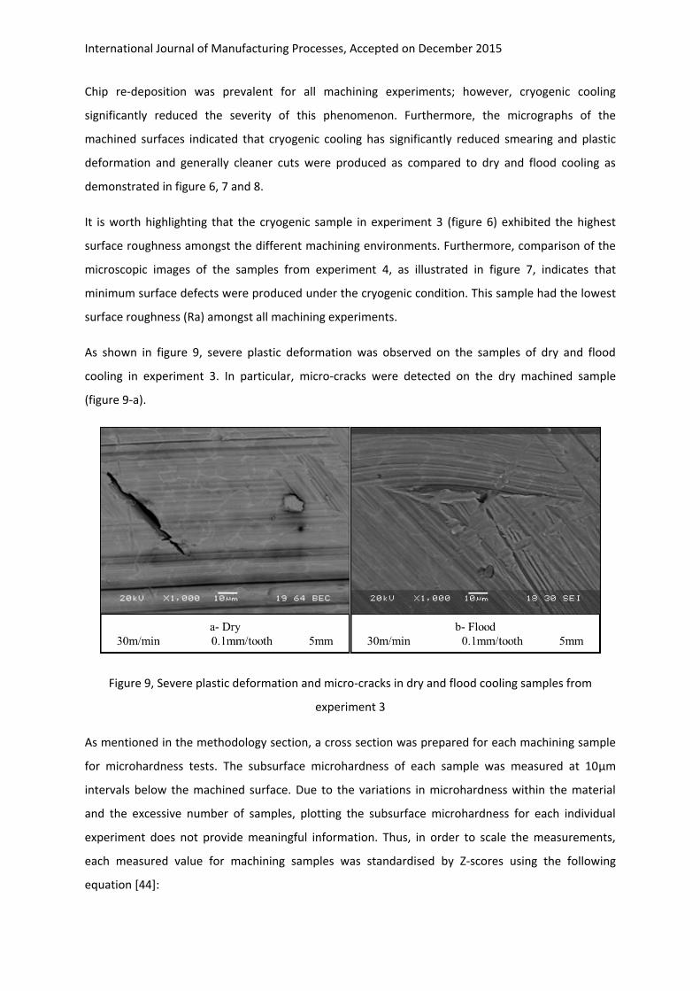
As shown in figure 9, severe plastic deformation was observed on the samples of dry and flood
cooling in experiment 3. In particular, micro-cracks were detected on the dry machined sample
(figure 9-a).
Figure 9, Severe plastic deformation and micro-cracks in dry and flood cooling samples from
experiment 3
As mentioned in the methodology section, a cross section was prepared for each machining sample
for microhardness tests. The subsurface microhardness of each sample was measured at 10μm
intervals below the machined surface. Due to the variations in microhardness within the material
and the excessive number of samples, plotting the subsurface microhardness for each individual
experiment does not provide meaningful information. Thus, in order to scale the measurements,
each measured value for machining samples was standardised by Z-scores using the following
equation [44]:

International Journal of Manufacturing Processes, Accepted on December 2015
Equation 1. Zi = (xi – μ)/σ
where Zi is the standardised value, xi is measured value, μ is the average of the measured values and
σ is the standard deviation of the measured values.
The average standardised microhardness at each distance below the machined surface was then
calculated for each machining environment and the results were plotted on a logarithmic scale. As
depicted in Figure 10, the analysis of subsurface microhardness indicates that the machining
operation has resulted in reduced microhardness immediately below the machined surface. The
extent of this change is more dominant in dry machining whilst it is almost identical in cryogenic and
flood cooling. The microhardness increases below the surface where it reaches its peak at almost
60μm where it downturns towards the substrate’s hardness. The subsurface microhardness for the
samples reached the substrate’s hardness at almost 100μm below the machined surface. The
noticeable difference in microhardness is that the increasing slope of microhardness for flood
cooling was lower than that of cryogenic and dry machining as shown in Figure 6. As a result, the
peak average subsurface microhardness for flood cooling was 60% less than that of cryogenic
cooling, whilst cryogenic cooling has the highest subsurface average microhardness peak (23%
higher than dry).
Figure 10, Average standardized subsurface Vickers microhardness of samples
for various machining environments
-3
-2.5
-2
-1.5
-1
-0.5
0
0.5
1
1.5
10 100 1000 10000
Sta
nd
ard
ised
Vic
ker
s h
ard
nes
s
Depth below the surface (μm)
Dry Cryogenic FloodMean = 284.896 VH

International Journal of Manufacturing Processes, Accepted on December 2015
5- Discussion
In cryogenic machining, a super cold liquefied gas, typically liquid nitrogen, replaces the
conventional cutting fluids as a means to control cutting temperature. Though, the liquefied gas not
only facilitates heat dissipation from the cutting zone but also modifies the material properties of
both cutting tool and workpiece [31]. This implies that the optimum cutting parameters
recommended by cutting tool manufacturers are not valid for the cryogenic machining environment.
In this study, an OA was used to generate a combination of cutting parameters at three levels based
on an assumption that the optimum cutting parameters are unknown for various machining
environments. Therefore, the resultant DoE covers a wider range of parameters for comparison.
Similarly, there are studies on single point cryogenic turning operations indicating improved
machinability [45]. However, the results of single point cutting operations cannot be extended to
intermittent multi-point milling operations. For instance, whilst there are investigations [46, 47]
indicating benefits of cryogenic cooling for turning stainless steel, a study by Nalbant and Yildiz [48]
concluded that cryogenic cooling does not provide any benefit for milling AISI 304 stainless steel.
Analysis of the data for surface roughness revealed that significant improvement have been
achieved through using liquid nitrogen for cryogenic machining as compared to flood and dry
machining. On average, cryogenic cooling resulted in an 18% reduction in surface roughness as
opposed to flood cooling. The lowest surface roughness produced in cryogenic cooling (experiment
C4) was 35% lower than the lowest surface roughness produced in experiment F1 in flood cooling.
The largest reduction in surface roughness is associated with experiment 8 where a 42% reduction
was recorded for cryogenic machining as opposed to flood cooling. Although the improvement
percentages are less than those for turning operations, the findings are in line with studies by
Dhananchezian and Kumar [34] and Sharma et al [45] where reduced surface roughness was
identified as a benefit of cryogenic cooling. Experiment 3 was found to be the only case where
cryogenic machining produced higher surface roughness than dry and flood cooling. Further
investigation of the surface using optical profilometry, as shown in Figure 11, revealed that extensive
plastic deformation in dry and flood cooling has filled the machining induced valleys resulting in
lower evaluation of surface roughness. This is proved by SEM micrographs of the machined surfaces.

International Journal of Manufacturing Processes, Accepted on December 2015
Figure 11, Optical scan of the machined surfaces in experiment 3
The microscopic analysis of the machined surfaces indicated that a considerable reduction in surface
defects has been achieved through cryogenic cooling. The samples machined in dry condition were
found to possess more surface defects with dominant plastic deformation and smearing. Analysis
indicated that subsurface microhardness is lower than material substrate up to 30μm below the
machined surface irrespective of machining environment. There are debates among researchers on
explaining the underlying reason for the reduction of microhardness adjacent to the machined
surface. Ginting and Nourai, [4] attributed the surface hardness reduction to localised heat
treatment on the machined surface as a result of the elevated cutting temperature. Furthermore,
the increase in the subsurface microhardness in the region of 30μm-100μm below the machined
surface is attributed to the strain hardening of titanium due to the plastic deformation during cutting
operations. Similar observations with regards to surface defects and subsurface microhardness are
reported by Ginting and Nourai [4] in dry end milling of titanium alloy.
6- Conclusions
This paper provides a comprehensive comparative investigation on cryogenic milling of Ti-6Al-4V
based on rigorous analysis. The following conclusions were drawn from this study:
- Cryogenic cooling has significantly improved surface roughness in end milling operations
using coated solid carbide cutters;
- Apart from the experiments conducted at low cutting speed (30m/min) and high feed (0.1),
cryogenic cooling produced lower surface roughness than dry and wet machining

International Journal of Manufacturing Processes, Accepted on December 2015
irrespective of cutting parameters. On average, the samples from cryogenic cooling
exhibited an 18% and 21% lower surface roughness in comparison to flood and dry
machining, respectively.
- The lowest surface roughness in cryogenic machining (Ra=0.58μm) is attributed to
experiment C4 with cutting speed of 115m/min, 0.03mm/tooth feed rate and 5mm depth of
cut which was 30% and 40% lower than that of flood and dry machining;
- Microscopic analysis of the machined surfaces indicated that plastic deformation and chip
re-deposition was dominant on all machined samples. Samples machined in cryogenic
cooling demonstrated lower surface defects when compared to flood and dry cooling.
- Analysis of subsurface microhardness of the machined samples indicated that the highest
increase in microhardness took place in cryogenic machining; however, the depth of
machined affected zone was lower in cryogenic and dry machining than that of flood
cooling. The effect of this phenomena on service performance of the parts requires further
investigation;
- Cryogenic cooling has exceptionally improved surface integrity of Ti-6Al-4V titanium alloy as
compared to conventional dry and flood cooling.
References
[1] Meza, F., L. Chen, and N. Hudson: Investigation of respiratory and dermal symptoms associated with metal working fluids at an aircraft engine manufacturing facility. American journal of industrial medicine. vol. 56(12): pp. 1394-1401 (2013).
[2] Shokrani, A., V. Dhokia, and S.T. Newman: Environmentally conscious machining of difficult-to-machine materials with regard to cutting fluids. International Journal of Machine Tools and Manufacture. vol. 57: pp. 83-101 (2012).
[3] Clarens, A.F., K.F. Hayes, and S.J. Skerlos: Feasibility of Metalworking Fluids Delivered in Supercritical Carbon Dioxide. Journal of Manufacturing Processes. vol. 8(1): pp. 47-53 (2006).
[4] Ginting, A. and M. Nouari: Surface integrity of dry machined titanium alloys. International Journal of Machine Tools and Manufacture. vol. 49(3–4): pp. 325-332 (2009).
[5] Ezugwu, E., J. Bonney, and Y. Yamane: An overview of the machinability of aeroengine alloys. Journal of Materials Processing Technology. vol. 134(2): pp. 233-253 (2003).
[6] Nath, C., S.G. Kapoor, A.K. Srivastava, and J. Iverson: Study of Droplet Spray Behavior of an Atomization-Based Cutting Fluid Spray System for Machining Titanium Alloys. Journal of Manufacturing Science and Engineering. vol. 136(2): pp. 021004-021004 (2014).
[7] Lütjering, G. and J.C. Williams: Titanium. 2 ed2007, New York: Springer. [8] Donachie, J.M.J.: Titanium - A Technical Guide (2nd Edition), 2000, ASM International. pp. 79-84. [9] Abdalla, H.S., W. Baines, G. McIntyre, and C. Slade: Development of novel sustainable neat-oil
metal working fluids for stainless steel and titanium alloy machining. Part 1. Formulation development. The International Journal of Advanced Manufacturing Technology. vol. 34(1-2): pp. 21-33 (2007).
[10] El Baradie, M.: Cutting fluids: Part I. characterisation. Journal of Materials Processing Technology. vol. 56(1-4): pp. 786-797 (1996).

International Journal of Manufacturing Processes, Accepted on December 2015
[11] Mondelin, A., C. Claudin, J. Rech, and F. Dumont: Effects of Lubrication Mode on Friction and Heat Partition Coefficients at the Tool–Work Material Interface in Machining. Tribology Transactions. vol. 54(2): pp. 247-255 (2011).
[12] COSHH. COSHH essentials for machining with metalworking fluids. Control of Substances Hazardous to Health (COSHH) 2015 [cited 2015 06-17-]; Available from: http://www.hse.gov.uk/metalworking/ecoshh.htm.
[13] CCOHS. Metalworking Fluids. Chemicals and Materials 2015 [cited 2015 06-17-]; Available from: http://www.ccohs.ca/oshanswers/chemicals/metalworking_fluids.html.
[14] OSHA. Metalworking Fluids. 2015 [cited 2015 06-17-]; Available from: https://www.osha.gov/SLTC/metalworkingfluids/healtheffects.html.
[15] HSE: Working safely with metalworking fluids - A guide for employees. Health and Safeftey Executive (HSE). vol. INDG365 (2011).
[16] Byrne, G. and E. Scholta: Environmentally Clean Machining Processes -- A Strategic Approach. CIRP Annals - Manufacturing Technology. vol. 42(1): pp. 471-474 (1993).
[17] Pusavec, F., D. Kramar, P. Krajnik, and J. Kopac: Transitioning to sustainable production – part II: evaluation of sustainable machining technologies. Journal of Cleaner Production. vol. 18(12): pp. 1211-1221 (2010).
[18] Suuronen, K., K. Aalto-Korte, R. Piipari, T. Tuomi, and R. Jolanki: Occupational dermatitis and allergic respiratory diseases in Finnish metalworking machinists. Occupational Medicine. vol. 57(4): pp. 277-283 (2007).
[19] Hannu, T., K. Suuronen, K. Aalto-Korte, K. Alanko, R. Luukkonen, M. Järvelä, R. Jolanki, and M.S. Jaakkola: Occupational respiratory and skin diseases among Finnish machinists: findings of a large clinical study. International archives of occupational and environmental health. vol. 86(2): pp. 189-197 (2013).
[20] Itschner, L., U. Hinnen, and P. Elsner: Skin risk assessment of metalworking fluids: a survey among Swiss suppliers. Dermatology. vol. 193(1): pp. 33-35 (1996).
[21] Naylor, S., C. Barber, B. Crook, W. Robertson, A. Robertson, E. Robinson, S. Rice, I. Gardner, R. Rawbone, G.S. Evans, M. Burd, M. Kinoulty, S. Burge, and J. Harris-Roberts: Powertrain Occupational Respiratory Disease Outbreak: Report of Immunological Investigation, 2007, Health and Safety Laboratory: Buxton, Derbyshire.
[22] Gordon, T.: Metalworking fluid—the toxicity of a complex mixture. Journal of Toxicology and Environmental Health, Part A. vol. 67(3): pp. 209-219 (2004).
[23] Tillie-Leblond, I., F. Grenouillet, G. Reboux, S. Roussel, B. Chouraki, C. Lorthois, J.-C. Dalphin, B. Wallaert, and L. Millon: Hypersensitivity pneumonitis and metalworking fluids contaminated by mycobacteria. European Respiratory Journal. vol. 37(3): pp. 640-647 (2011).
[24] Robertson, W., A.S. Robertson, C.B. Burge, V.C. Moore, M.S. Jaakkola, P.A. Dawkins, M. Burd, R. Rawbone, I. Gardner, and M. Kinoulty: Clinical investigation of an outbreak of alveolitis and asthma in a car engine manufacturing plant. Thorax. vol. 62(11): pp. 981-990 (2007).
[25] Clapp, R.W., M.M. Jacobs, and E.L. Loechler: Environmental and occupational causes of cancer: new evidence 2005-2007. Reviews on environmental health. vol. 23(1): pp. 1-38 (2008).
[26] Agalliu, I., D. Kriebel, M.M. Quinn, D.H. Wegman, and E.A. Eisen: Prostate cancer incidence in relation to time windows of exposure to metalworking fluids in the auto industry. Epidemiology. vol. 16(5): pp. 664-671 (2005).
[27] Kaynak, Y., T. Lu, and I. Jawahir: Cryogenic Machining-Induced Surface Integrity: A Review and Comparison with Dry, MQL, and Flood-Cooled Machining. Machining Science and Technology. vol. 18(2): pp. 149-198 (2014).
[28] Uehara, K. and S. Kumagai: Chip formation, surface roughness and cutting force in cryogenic machining. Annals of CIRP. vol. 17(1): pp. 409-416 (1968).
[29] Hong, S.Y. and Y. Ding: Cooling approaches and cutting temperatures in cryogenic machining of Ti-6Al-4V. International Journal of Machine Tools and Manufacture. vol. 41(10): pp. 1417-1437 (2001).

International Journal of Manufacturing Processes, Accepted on December 2015
[30] Hong, S.Y., Y. Ding, and W. Jeong: Friction and cutting forces in cryogenic machining of Ti-6Al-4V. International Journal of Machine Tools and Manufacture. vol. 41(15): pp. 2271-2285 (2001).
[31] Hong, S.Y., I. Markus, and W. Jeong: New cooling approach and tool life improvement in cryogenic machining of titanium alloy Ti-6Al-4V. International Journal of Machine Tools and Manufacture. vol. 41(15): pp. 2245-2260 (2001).
[32] Wang, Z., K. Rajurkar, J. Fan, and G. Petrescu: Cryogenic Machining of Tantalum. Journal of Manufacturing Processes. vol. 4(2): pp. 122-127 (2002).
[33] Wang, Z. and K. Rajurkar: Cryogenic machining of hard-to-cut materials. Wear. vol. 239(2): pp. 168-175 (2000).
[34] Dhananchezian, M. and M.P. Kumar: Cryogenic turning of the Ti–6Al–4V alloy with modified cutting tool inserts. Cryogenics. vol. 51(1): pp. 34-40 (2011).
[35] Pusavec, F. and J. Kopac: Achieving and Implementation of Sustainability Principles in Machining Processes. Journal of Advances in Production Engineering and Management. vol. 3-4: pp. 58-69 (2009).
[36] Shokrani, A., V. Dhokia, P. Munoz-Escalona, and S. Newman: State-of-the-art cryogenic machining and processing. International Journal of Computer Integrated Manufacturing. vol. 26(7): pp. 616-648 (2013).
[37] Montgomery, D.C.: Design and Analysis of Experiments (8th Edition)2013, New York: John Wiley & Sons.
[38] BS-ISO-3534-3:2013: Statistics - Vocabulary and Symbols, in Part 3: Design of Experiments2013, British Standard Institution: London.
[39] Shokrani, V. Dhokia, S.T. Newman, and R. Imani-Asrai: An Initial Study of the Effect of Using Liquid Nitrogen Coolant on the Surface Roughness of Inconel 718 Nickel-Based Alloy in CNC Milling. Procedia CIRP. vol. 3(0): pp. 121-125 (2012).
[40] Muñoz-Escalona, P., A. Shokrani, and S.T. Newman: Influence of cutting environments on surface integrity and power consumption of austenitic stainless steel. Robotics and Computer-Integrated Manufacturing. vol. In press (2015).
[41] BS-EN-ISO-4288: Geometric Product Specification (GPS) in Surface texture —Profile method: Rules and procedures for the assessment of surface texture1998, British-Standard-Institute: London.
[42] BS-EN-ISO-3274: Geometric Product Specification (GPS) in Surface texture: Profile method — Nominal characteristics of contact (stylus) instruments —1998, British-Standard-Institute: London.
[43] BS-EN-ISO-4287: Geometric Product Specification (GPS) in Surface texture —Profile method: Terms, definitions and surface texture parameters1998, British-Standard-Institute: London.
[44] Fajgelj, A., M. Belli, and U. Sansone: Combining and Reporting Analytical Results, 2007, Royal Society of Chemistry: Cambridge.
[45] Sharma, V.S., M. Dogra, and N.M. Suri: Cooling techniques for improved productivity in turning. International Journal of Machine Tools and Manufacture. vol. 49(6): pp. 435-453 (2009).
[46] Hong, S.Y. and M. Broomer: Economical and ecological cryogenic machining of AISI 304 austenitic stainless steel. Clean Technologies and Environmental Policy. vol. 2(3): pp. 157-166 (2000).
[47] Kalyankumar, K. and S. Choudhury: Investigation of tool wear and cutting force in cryogenic machining using design of experiments. Journal of Materials Processing Technology. vol. 203(1-3): pp. 95-101 (2008).
[48] Nalbant, M. and Y. Yildiz: Effect of cryogenic cooling in milling process of AISI 304 stainless steel. Transactions of Nonferrous Metals Society of China. vol. 21(1): pp. 72-79 (2011).