
Energy Chain Systems E2 “mini” - igus® Inc. · For Classic E2 Mini Energy Chain ... B15/B15i,...
13
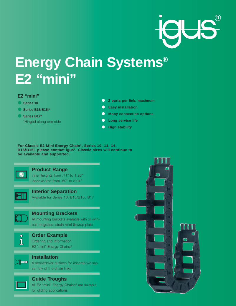
Energy Chain Systems ® E2 “mini” Product Range Inner heights from .71” to 1.26” Inner widths from .59” to 3.94” Interior Separation Available for Series 10, B15/B15i, B17 Mounting Brackets All mounting brackets available with or with- out integrated, strain relief tiewrap plate Order Example Ordering and information E2 “mini” Energy Chains ® Installation A screwdriver suffices for assembly/disas- sembly of the chain links Guide Troughs All E2 “mini” Energy Chains ® are suitable for gliding applications E2 “mini” Series 10 Series B15/B15i* Series B17* *Hinged along one side For Classic E2 Mini Energy Chain ® , Series 10, 11, 14, B15/B15i, please contact igus ® . Classic sizes will continue to be available and supported. • 2 parts per link, maximum • Easy installation • Many connection options • Long service life • High stability
Transcript of Energy Chain Systems E2 “mini” - igus® Inc. · For Classic E2 Mini Energy Chain ... B15/B15i,...
Energy Chain Systems®
E2 “mini”
Product RangeInner heights from .71” to 1.26”
Inner widths from .59” to 3.94”
Interior SeparationAvailable for Series 10, B15/B15i, B17
Mounting BracketsAll mounting brackets available with or with-
out integrated, strain relief tiewrap plate
Order ExampleOrdering and information
E2 “mini” Energy Chains®
InstallationA screwdriver suffices for assembly/disas-
sembly of the chain links
Guide TroughsAll E2 “mini” Energy Chains® are suitable
for gliding applications
E2 “mini”Series 10
Series B15/B15i*
Series B17*
*Hinged along one side
For Classic E2 Mini Energy Chain®, Series 10, 11, 14,B15/B15i, please contact igus®. Classic sizes will continue tobe available and supported.
• 2 parts per link, maximum
• Easy installation
• Many connection options
• Long service life
• High stability

7 Widths9 Bending Radii
Interior separation pos-sible
Mounting bracket withan without strain relief
tiewrap plates
Quickfix: mountingbracket with pin
Call for availability
When not to use the Series
10 E2 “mini”:
If snap-open links are nec-
essary
Series 15 “Zipper”,
Chapter 3
If quick insertion of cables
with pre-assembled con-
nectors is required
Series E14 “E-Z Chain”,
Chapter 2
-
4.26
Series 10 E2 “mini”
Product Range:
Inner widths (Bi) inches (mm): .59 (15), .98 (25), 1.50 (38), 1.97
(50), 2.48 (63), 3.15 (80), 3.94 (100)
Bending Radii (R) inches (mm): 1.10 (028), 1.50 (038), 1.89 (048),
2.95 (75), 3.94 (100), 4.33 (110),
4.92 (125), 5.71 (145), 7.09 (180)
Pitch: 1.20 (30.5 mm)/link =
10.06 links/ft (33 links/m)
39.6 (1006.5mm)
Large pins and double stopdog for long service life andlong unsupported length
.71
FLG
FLB
H
S (FLG)
S (FLB)
HF
Unsupported length
FLB = unsupported with permitted sag
FLG = unsupported with straight upper run
Price Index
FLG
FLB
0 1.64 3.28 4.92
.34
.67
1.34
6.56
1.01
0 3.28 6.56 13.129.84
Fill
wei
ght
in lb
s/ft
Unsupported length in ft FLB / FLG
Length of travel S in ft
When to use the Series 10 E2
“mini”:
If snap-open links are not
necessary
If connection options are
required (Quicksnap,
Quickfix, etc.)
If small but very stable
chain is required

Part No. Bi Ba
10-015 .59 (15) 1.02 (26)
10-025 .98 (25) 1.42 (36)
10-038 1.50 (38) 1.93 (49)
10-050 1.97 (50) 2.40 (61)
10-5 2.48 (63) 2.95 (76)
10-6 3.15 (80) 3.70 (94)
10-7 3.94 (100) 4.45 (113)
10
PD
F:
ww
w.ig
us.
com
/ech
ain
pd
f.as
pS
pec
s/C
AD
/RF
Q:
ww
w.ig
us.
com
/ech
ain
.asp
Ro
HS
info
: w
ww
.igu
s.co
m/R
oH
S.a
sp
4.27
Series 10 E2 “mini”
Interior separation Vertical Separators
Unassembled Part No. 101
Assembled Part No. 111.06(1.5)
.31 (8)
Chapter 9
Bi
.63max.
Ba
.71
(1
8)
.91
(2
3)
Installation Dimensions
1.50 (38)1.20(30.5)
H
H-.
91 (2
3)
.91
(23)
R
D S/2
S
*The required clearance height is HF = H+ .79 (20) with 1.01 lbs/ft (1.5 kg/m) fillweight. Please consult igus® if space isparticularly restricted.
Pitch: = 1.20 (30.5 mm) per linkLinks per ft (m): = 10.06 (33)Chain length: = S + K
2
Moving end
Fixed end
Supplement part no. with required radiusfor example, 10-25-100-0
Bending Radiifor ALL Widths
1.10 (028)1.50 (038)1.89 (048)2.95 (075)3.94 (100)4.33 (110)4.92 (125)5.71 (145)7.09 (180)
R 2.95 (075) 3.94 (100) 4.33 (110)
H* 6.89 (175) 8.86 (225) 9.65 (245)
D 4.72 (120) 5.71 (145) 6.10 (155)
K 11.81 (300) 14.76 (375) 16.14 (410)
R 4.92 (125) 5.71 (145) 7.09 (180)
H* 10.83 (275) 12.40 (315) 15.16 (385)
D 6.69 (170) 7.48 (190) 8.86 (225)
K 17.91 (455) 20.47 (520) 24.80 (630)
R 1.10 (028) 1.50 (038) 1.89 (048)
H* 3.15 (80) 3.94 (100) 4.72 (120)
D 2.76 (70) 3.15 (80) 3.54 (90)
K 5.91 (150) 7.28 (185) 8.46 (215)
These separators are used when vertical subdivision is required.

10
4.28
10… 34 = Full set, each part with pin/bore10… 3 = Mounting bracket with bore10... 4 = Mounting bracket with pin
105-34-P(Z) – 107-34-P(Z)1015-34-P(Z) – 1050-34-P(Z)
B A
.67 (17) .83 (21).67 (17).83 (21)
.24 (6.2)A B
.67 (17)
Mounting Brackets (2 options for all applications)
Option 1: pivoting
• Pivoting• Short and long travel• Confined installation condi-
tions• Corrosion-resistant 27°
90°
27° 90°
27°
90°
90°
27°
AB BA
.30(7.5)
.65(16.5)
.55(14)
.30(7.5)
.43
(11)
.67(17)
.65(16.5)
.55(14)
.25(6.5)
10....3Moving end
10....4Fixed end
10....3 10....4
Chain Type Part No. Part No. Dimension A Dimensions BFull set with Mounting in. (mm) in. (mm)Tiewrap Plate Bracket Set
10-015 1015-34PZ 1015-34P — — 1.00 (25.5)
10-025 1025-34PZ 1025-34P .39 (10) 1.40 (35.5)
10-038 1038-34PZ 1038-34P .91 (23) 1.91 (48.5)
10-050 1050-34PZ 1050-34P 1.38 (35) 2.38 (60.5)
10-5 105-34PZ 105-34P 1.89 (48) 2.95 (75.0)
10-6 106-34PZ 106-34P 2.56 (65) 3.62 (92.0)
10-7 107-34PZ 107-34P 3.35 (85) 4.41 (112.0)
10…12 = Full set, each part with pin/bore10… 1 = Mounting bracket with bore10... 2 = Mounting bracket with pin
105-12-P(Z) – 107-12-P(Z)1015-12-P(Z) – 1050-12-P(Z)
B A
.67 (17) .83 (21).67 (17).83 (21)
.24 (6.2)A B
.67 (17)
Mounting Brackets (2 options for all applications)
Option 2: locking
• Locked connections• Vertical hanging/standing
travels• Extreme accelerations• Corrosion-resistant
90°
90°
AB BA
.30(7.5)
.65(16.5)
.55(14)
.30(7.5)
.43
(11)
.67(17)
.65(16.5)
.55(14)
.25(6.5)
10....1Moving end
10....2Fixed end
10....1 10....2
Chain Type Part No. Part No. Dimension A Dimensions BFull set with Mounting in. (mm) in. (mm)Tiewrap Plate Bracket Set
10-015 1015-12PZ 1015-12P — — 1.00 (25.5)
10-25 1025-12PZ 1025-12P .39 (10) 1.40 (35.5)
10-38 1038-12PZ 1038-12P .91 (23) 1.91 (48.5)
10-50 1050-12PZ 1050-12P 1.38 (35) 2.38 (60.5)
10-5 105-12PZ 105-12P 1.89 (48) 2.95 (75.0)
10-6 106-12PZ 106-12P 2.56 (65) 3.62 (92.0)
10-7 107-12PZ 107-12P 3.35 (85) 4.41 (112.0)
Inte
rnet
: h
ttp
://w
ww
.igu
s.co
mem
ail:
sale
s@ig
us.
com
Qu
ickS
pec
: h
ttp
://w
ww
.igu
s.co
m/q
s/ec
hai
n.a
sp
Tele
ph
on
e1-
800-
521-
2747
Fax
1-
401-
438-
7270
igu
s®E
ner
gy
Ch
ain
Sys
tem
s®
Series 10 E2 “mini”

10
1. Chain selection:
10-025-038-0
Color
Radius
Width
Chain type
2. Mounting brackets:
1025-12PZ
Full set
Chain width
3. Interior separation
2 separators unassembled (Part No. 101)
or,
assembled every other link (Part No. 111)
Alternative interior separation configura-
tion according to design layout possible.
Chain Type Weight Per Link Weight(oz.) (g) (lbs/ft) (kg/m)
10-15 0.35 (≈ 10) 0.24 (≈ 0.35)
10-25 0.42 (≈ 12) 0.27 (≈ 0.40)
10-38 0.49 (≈ 14) 0.31 (≈ 0.46)
10-50 0.56 (≈ 16) 0.35 (≈ 0.52)
10-5 0.67 (≈ 19) 0.42 (≈ 0.63)
10-6 0.74 (≈ 21) 0.47 (≈ 0.70)
10-7 1.02 (≈ 29) 0.51 (≈ 0.76)
4.29
PD
F:
ww
w.ig
us.
com
/ech
ain
pd
f.as
pS
pec
s/C
AD
/RF
Q:
ww
w.ig
us.
com
/ech
ain
.asp
Ro
HS
info
: w
ww
.igu
s.co
m/R
oH
S.a
sp
Chapter 9
Order Example and Technical Data:Series 10 E2 “mini”
For 16.4 ft (5 m) chain, color black, with mounting brackets and two separators:
16.4 ft (5 m) 10-025-038-0 and 1025-12PZ and two separators 111 assembled every other link
165 links — 10.06 links/ft (33 links/m)
Order example 10-25...
Bi = .98 (25)
Ba = 1.42 (36)
.71
(1
8)
.91
(2
3)
Details of material properties
Design, Chapter 1
Technical data
Material igumid G
Permitted temperature -40°/+266°F (-40°/+130°C)
Gliding speed max. 16.4 ft/s (5 m/s)
Unsupported V max. 32.8 ft/s (10 m/s)
Flammability class VDE 0304 IIC UL94 HB
7 Widths8 Bending Radii
Interior separationpossible
Mounting bracket withor without strain relief
tiewrap plates
Quickfix: mountingbracket with pin
Call for availability
4.30
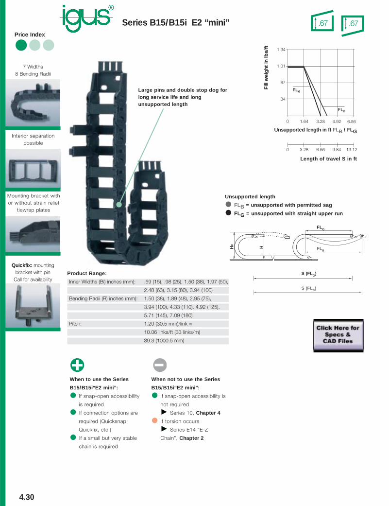
Series B15/B15i E2 “mini”
Product Range:
Inner Widths (Bi) inches (mm): .59 (15), .98 (25), 1.50 (38), 1.97 (50),
2.48 (63), 3.15 (80), 3.94 (100)
Bending Radii (R) inches (mm): 1.50 (38), 1.89 (48), 2.95 (75),
3.94 (100), 4.33 (110), 4.92 (125),
5.71 (145), 7.09 (180)
Pitch: 1.20 (30.5 mm)/link =
10.06 links/ft (33 links/m)
39.3 (1000.5 mm)
When to use the Series
B15/B15i“E2 mini”:
If snap-open accessibility
is required
If connection options are
required (Quicksnap,
Quickfix, etc.)
If a small but very stable
chain is required
When not to use the Series
B15/B15i“E2 mini”:
If snap-open accessibility is
not required
Series 10, Chapter 4
If torsion occurs
Series E14 “E-Z
Chain”, Chapter 2
-
Large pins and double stop dog forlong service life and longunsupported length
.67 .67
FLG
FLB
H
S (FLG)
S (FLB)
HF
Unsupported length
FLB = unsupported with permitted sag
FLG = unsupported with straight upper run
Price Index
0 1.64 3.28 4.92
.34
.67
1.34
FLG
FLB
6.56
1.01
0 3.28 6.56 13.129.84
Fill
wei
ght
in lb
s/ft
Unsupported length in ft FLB / FLG
Length of travel S in ft

B15B15i
PD
F:
ww
w.ig
us.
com
/ech
ain
pd
f.as
pS
pec
s/C
AD
/RF
Q:
ww
w.ig
us.
com
/ech
ain
.asp
Ro
HS
info
: w
ww
.igu
s.co
m/R
oH
S.a
sp
4.31
Series B15/B15i E2 “mini”
Series B15(snap-open along outer radius)
Series B15i(snap-open along inner radius
Chapter 9
.94
(2
4)
.67
(1
7)
Ba
Bi
.55max.
Supplement part no. with required radiusfor example, B15-025-100-0
Bending Radiifor ALL Widths
1.50 (038)1.89 (048)2.95 (075)3.94 (100)4.33 (110)4.92 (125)5.71 (145)7.09 (180)
Installation Dimensions
1.50 (38)1.20
(30.5)
H
H-.
94 (2
4)
.94
(24)
R
D S/2
S
*The required clearance height is HF = H + .79 (20) with1.01 lbs/ft (1.5 kg/m) fill weight. Please consult igus® ifspace is particularly restricted.
Pitch: = 1.20 (30,5 mm )per linkLinks per ft (m): = 10.06 (33)Chain length: = S + K
2
R 4.33 (110) 4.92 (125) 5.71 (145) 7.09 (180)
H* 9.65 (245) 10.83 (275) 12.40 (315) 15.16 (385)
D 6.10 (155) 6.69 (170) 7.48 (190) 8.86 (225)
K 16.14 (410) 17.91 (455) 20.47 (520) 24.80 (630)
R 1.50 (38) 1.89 (48) 2.95 (75) 3.94 (100)
H* 3.94 (100) 4.72 (120) 6.89 (175) 8.86 (225)
D 3.15 (80) 3.54 (90) 4.72 (120) 5.71 (145)
K 7.28 (185) 8.46 (215) 11.81 (300) 14.76 (375)
Moving end
Fixed end
Part No. Bi Ba
B15-015 .59 (15) 1.02 (26)
B15-025 .98 (25) 1.42 (36)
B15-038 1.50 (38) 1.93 (49)
B15-050 1.97 (50) 2.40 (61)
B15-5 2.48 (63) 2.99 (76)
B15-6 3.15 (80) 3.70 (94)
B15-7 3.94 (100) 4.45 (113)
.55max.
Ba
Bi
.67
(1
7)
.94
(2
4)
Supplement part no. with required radiusfor example, B15i-025-100-0
Bending Radiifor ALL Widths
1.50 (038)1.89 (048)2.95 (075)3.94 (100)4.33 (110)4.92 (125)5.71 (145)7.09 (180)
Part No. Bi Ba
B15i-015 .59 (15) 1.02 (26)
B15i-025 .98 (25) 1.42 (36)
B15i-038 1.50 (38) 1.93 (49)
B15i-050 1.97 (50) 2.40 (61)
B15i-5 2.48 (63) 2.99 (76)
B15i-6 3.15 (80) 3.70 (94)
B15i-7 3.94 (100) 4.45 (113)
Interior Separation
Option 1: vertical separatorsVertical separators are used if only a verticalsubdivision is required. A slotted separator isused for this subdivision. This separator canalso be used with full-width shelves for acontinuous horiozontal subdivision.
.20
(5)
.30
(7.5
0)
154110-XX
.08
(2)
156
.20
(5)
.30
(7.5
0)
Option 2: full-width shelfInterior separation with continuous horizontal sub-division is practical is using a large number of thincables with similar or identical diameters.
Width X Part No. Part No. in. (mm) Unassembled Assembled
.59 (015) 110-15 111-15
.98 (025) 110-25 111-25
1.50 (038) 110-38 111-38
1.97 (050) 110-50 111-50
2.48 (063) 110-63 111-63
3.15 (080) 110-80 111-80
3.94 (100) 110-100 111-100
.31 (8)
.06 (1.5)
X
t = .08 (2)
Vertical Separator, Slotted
Unassembled Part No. 153
Assembled Part No. 154.19 (4.75)
.06 (1.5)
Side Plate
Unassembled Part No. 155
Assembled Part No. 156

B15B15iIn
tern
et:
htt
p:/
/ww
w.ig
us.
com
emai
l: sa
les@
igu
s.co
mQ
uic
kSp
ec:
htt
p:/
/ww
w.ig
us.
com
/qs/
ech
ain
.asp
Tele
ph
on
e1-
800-
521-
2747
Fax
1-
401-
438-
7270
igu
s®E
ner
gy
Ch
ain
Sys
tem
s®
4.32
Series B15/B15i E2 “mini”
10… 34 = Full set, each part with pin/bore10… 3 = Mounting bracket with bore10... 4 = Mounting bracket with pin
105-34-P(Z) – 107-34-P(Z)1015-34-P(Z) – 1050-34-P(Z)
B A
.67 (17) .83 (21).67 (17).83 (21)
.24 (6.2)A B
.67 (17)
Mounting Brackets (2 options for all applications)
Option 1: pivoting
• Pivoting• Short and long travel• Space-restricted conditions• Corrosion-resistant
27°
90°
27° 90°
27°
90°
90°
27°
AB BA
.30(7.5)
.65(16.5)
.55(14)
.30(7.5)
.43
(11)
.67(17)
.65(16.5)
.55(14)
.25(6.5)
10....3Moving end
10....4Fixed end
10....3 10....4
Chain Type Part No. Part No. Dimension A Dimensions BFull set with Mounting in. (mm) in. (mm)Tiewrap Plate Bracket Set
B15/B15i-015 1015-34PZ 1015-34P — — 1.00 (25.5)
B15/B15i-025 1025-34PZ 1025-34P .39 (10) 1.40 (35.5)
B15/B15i-038 1038-34PZ 1038-34P .91 (23) 1.91 (48.5)
B15/B15i-050 1050-34PZ 1050-34P 1.54 (39) 2.38 (60.5)
B15/B15i-5 105-34PZ 105-34P 1.89 (48) 2.95 (75.0)
B15/B15i-6 106-34PZ 106-34P 2.56 (65) 3.62 (92.0)
B15/B15i-7 107-34PZ 107-34P 3.35 (85) 4.41 (112.0)
Chain Type Part No. Part No. Dimension A Dimensions BFull set with Mounting in. (mm) in. (mm)Tiewrap Plate Bracket Set
B15/B15i-015 1015-12PZ 1015-12P — — 1.00 (25.5)
B15/B15i-025 1025-12PZ 1025-12P .39 (10) 1.40 (35.5)
B15/B15i-038 1038-12PZ 1038-12P .91 (23) 1.91 (48.5)
B15/B15i-050 1050-12PZ 1050-12P 1.54 (39) 2.38 (60.5)
B15/B15i-5 105-12PZ 105-12P 1.89 (48) 2.95 (75.0)
B15/B15i-6 106-12PZ 106-12P 2.56 (65) 3.62 (92.0)
B15/B15i-7 107-12PZ 107-12P 3.35 (85) 4.41 (112.0)
10…12 = Full set, each part with pin/bore10… 1 = Mounting bracket with bore10... 2 = Mounting bracket with pin
105-12-P(Z) – 107-12-P(Z)1015-12-P(Z) – 1050-12-P(Z)
B A
.67 (17) .83 (21).67 (17).83 (21)
.24 (6.2)A B
.67 (17)
Option 2: locking
• Locked connections• Short and long travels• Extreme accelerations• Corrosion-resistant
AB BA
.30(7.5)
.65(16.5)
.55(14)
.30(7.5)
.43
(11)
.67(17)
.65(16.5)
.55(14)
.25(6.5)
10....1Moving end
10....2Fixed end
10....1 10....2
B15B15i
PD
F:
ww
w.ig
us.
com
/ech
ain
pd
f.as
pS
pec
s/C
AD
/RF
Q:
ww
w.ig
us.
com
/ech
ain
.asp
Ro
HS
info
: w
ww
.igu
s.co
m/R
oH
S.a
sp
4.33
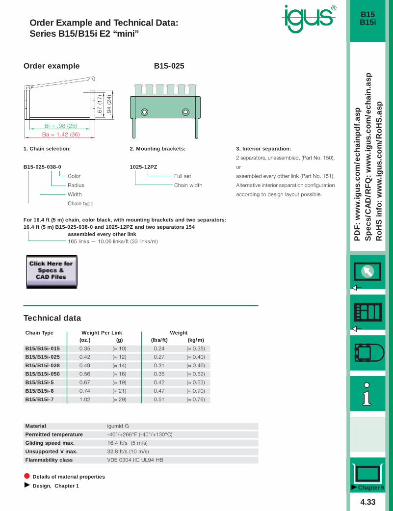
Order Example and Technical Data:Series B15/B15i E2 “mini”
Chapter 9
1. Chain selection:
B15-025-038-0
Color
Radius
Width
Chain type
2. Mounting brackets:
1025-12PZ
Full set
Chain width
3. Interior separation:
2 separators, unassembled, (Part No. 150),
or
assembled every other link (Part No. 151).
Alternative interior separation configuration
according to design layout possible.
For 16.4 ft (5 m) chain, color black, with mounting brackets and two separators:16.4 ft (5 m) B15-025-038-0 and 1025-12PZ and two separators 154
assembled every other link165 links — 10.06 links/ft (33 links/m)
Order example B15-025
Details of material properties
Design, Chapter 1
Material igumid G
Permitted temperature -40°/+266°F (-40°/+130°C)
Gliding speed max. 16.4 ft/s (5 m/s)
Unsupported V max. 32.8 ft/s (10 m/s)
Flammability class VDE 0304 IIC UL94 HB
Technical data
.94
(2
4)
.67
(1
7)
Ba = 1.42 (36)
Bi = .98 (25)
Chain Type Weight Per Link Weight(oz.) (g) (lbs/ft) (kg/m)
B15/B15i-015 0.35 (≈ 10) 0.24 (≈ 0.35)
B15/B15i-025 0.42 (≈ 12) 0.27 (≈ 0.40)
B15/B15i-038 0.49 (≈ 14) 0.31 (≈ 0.46)
B15/B15i-050 0.56 (≈ 16) 0.35 (≈ 0.52)
B15/B15i-5 0.67 (≈ 19) 0.42 (≈ 0.63)
B15/B15i-6 0.74 (≈ 21) 0.47 (≈ 0.70)
B15/B15i-7 1.02 (≈ 29) 0.51 (≈ 0.76)

7 Widths5 Bending Radii
Interior separationpossible
Mounting bracket withor without strain relief
tiewrap plates
4.34
Series B17 E2 “mini”
Product Range:
Inner Widths (Bi) inches (mm): .59 (15), .98 (25), 1.50 (38), 1.97 (50),
2.48 (63), 3.15 (80), 3.94 (100)
Bending Radii (R) inches (mm): 1.89 (48), 2.48 (63), 2.95 (75),
3.94 (100), 4.92 (125)
Pitch: 1.20 (30.5 mm)/link =
10.06 links/ft (33 links/m)
39.6(1006.5 mm)
When to use the Series B17:
If snap-open accessibility
is required
If a rather small chain with
broad inner width is
required
If reverse bending radius is
required
When not to use the Series
B17:
If quick cable/hose accessi-
bility is required
Series 17 “Zipper”,
Chapter 3
If quick insertion of cables
with pre-assembled
connectors is required
Series E16 “E-Z Chain”,
Chapter 2
-
Snap-open with film-hinge
Minimum pitch forquiet operation
1.26
FLG
FLB
H
S (FLG)
S (FLB)
HF
Unsupported length
FLB = unsupported with permitted sag
FLG = unsupported with straight upper run
Price Index
0
FLG FLB
0
.82 2.46 4.10
.17
.50
.84
4.92 8.20
1.64 3.28 4.92
.34
.67
1.01
3.28 6.56 9.841.64
Fill
wei
ght
in lb
s/ft
Unsupported length in ft FLB / FLG
Length of travel S in ft

B17
PD
F:
ww
w.ig
us.
com
/ech
ain
pd
f.as
pS
pec
s/C
AD
/RF
Q:
ww
w.ig
us.
com
/ech
ain
.asp
Ro
HS
info
: w
ww
.igu
s.co
m/R
oH
S.a
sp
4.35
* Radius 048 only for B17-1 and B17-3 Others upon request
Series B17 E2 “mini”
Series B17 Energy Chain®
(snap-open along outer radius)
1.5
4 (
39
)
1.2
6 (
32
)
Ba
Bi
1.10”max.
Installation Dimensions
1.50 (38)1.20
(30.5)
H
H-1
.54
(39)
1.54
(39)
R
D S/2
S
*The required clearance height is HF = H + .98 (25) with 1.01 (1.5kg/m) fill weight. Please consult igus is space is particularlyrestricted.
Pitch: = 1.20 (30.5 mm) per linkLinks per ft (m): = 10.06 (33)Chain length: = S + K
2
Moving end
Fixed end
Part No. Bi Ba
B17-1 .59 (15) 1.02 (26)
B17-2 .98 (25) 1.42 (36)
B17-3 1.50 (38) 1.93 (49)
B17-4 1.97 (50) 2.40 (61)
B17-5 2.48 (63) 2.99 (76)
B17-6 3.15 (80) 3.66 (93)
B17-7 3.94 (100) 4.45 (113)
Supplement part no. with required radiusfor example, B17-1-063-0
Bending Radiifor ALL Widths
1.89 (048)*2.48 (063)2.95 (075)3.94 (100)4.92 (125)
R 1.89 (48) 2.48 (63) 2.95 (75) 3.94 (100) 4.92 (125)
H* 5.31 (135) 6.50 (165) 7.44 (189) 9.41 (239) 11.38 (289)
D 3.94 (100) 4.53 (115) 5.12 (130) 6.10 (155) 7.09 (180)
K 8.66 (220) 10.83 (275) 12.01 (305) 15.55 (395) 18.70 (475)
Interior Separation
Option 1: vertical separatorsSeparators are used when vertical compartmentaliza-tion of the Energy Chain® is the only type of separa-tion required. Spacers can be used on either side ofeach separator to maintain the distance betweenthem. Spacers are necessary primarily with side-mounted chains.
.59
(1
5)
.59
(1
5)
172111-XX
.08
(2)
176
.20
(5)
.20
(5)
Option 2: full-width shelfFull-width shelves are used with applications involvingnumerous thin cables with similar or identical diame-ters. This shelf slides into place and spans the entirewidth of the chain.
Width X Part No. Part No. in. (mm) Unassembled Assembled
.59 (015) 110-15 111-15
.98 (025) 110-25 111-25
1.50 (038) 110-38 111-38
1.97 (050) 110-50 111-50
2.48 (063) 110-63 111-63
3.15 (080) 110-80 111-80
3.94 (100) 110-100 111-100
.19 (4.75)
.06 (1.5)
X
t = .08 (2)
Vertical Separators, Slottedfor B17-5 to B17-7
Unassembled Part No. 173
Assembled Part No. 174.39 (10)
.06 (1.5)
Vertical Separators, slottedfor B17-1 to B17-4
Unassembled Part No. 171
Assembled Part No. 172.39 (10)
.08 (2)
Side Plates for B17-1 to B17-4
Unassembled Part No. 175
Assembled Part No. 176 .19 (4.75)
.04 (1.0)
Side Plates for B17-5 to B17-7
Unassembled Part No. 177
Assembled Part No. 178

B17In
tern
et:
htt
p:/
/ww
w.ig
us.
com
emai
l: sa
les@
igu
s.co
mQ
uic
kSp
ec:
htt
p:/
/ww
w.ig
us.
com
/qs/
ech
ain
.asp
Tele
ph
on
e1-
800-
521-
2747
Fax
1-
401-
438-
7270
igu
s®E
ner
gy
Ch
ain
Sys
tem
s®
4.36
Series B17 E2 “mini”
Mounting Brackets
90°
90°
117....1PZMoving end
117....2PZFixed end
B
.67 (17) .55
(14)
.28
(7)
.55
(14)
.28
(7)
.20 (5.2) .20 (5.2)
A BA
.39 (10)
90˚
.39 (10)
90˚
.67 (17) .67 (17)117....1 117....2
Polymer, one-piece
• one-piece mounting bracket
• Corrosion resistant
• Available pre-assembled
• Inner and outer attachment possible
• Flush mounting
• With strain relief tiewrap plates
117-1-12P(Z): Center bores only117-2-12P(Z) — 117-7-12P(Z): Outer bores only
117…12 = Full set, each party with pin/bore117… 1 = Mounting bracket with bore117... 2 = Mounting bracket with pin
Chain Type Part No. Set Part No. Number Dimension A Dimensions BFull set with Mounting of Teeth in. (mm) in. (mm)Tiewrap Plate Bracket Set
B17-1 117-1-12PZ 117-1-12P 2 — — 1.00 (25,5)
B17-2 117-2-12PZ 117-2-12P 3 .47 (12) 1.40 (35,5)
B17-3 117-3-12PZ 117-3-12P 4 .98 (25) 1.91 (48,5)
B17-4 117-4-12PZ 117-4-12P 5 1.46 (37) 2.38 (60,5)
B17-5 117-5-12PZ 117-5-12P 6 1.89 (48) 2.99 (76,0)
B17-6 117-6-12PZ 117-6-12P 8 2.56 (65) 3.66 (93,0)
B17-7 117-7-12PZ 117-7-12P 10 3.35 (85) 4.45 (113,0)

B17
PD
F:
ww
w.ig
us.
com
/ech
ain
pd
f.as
pS
pec
s/C
AD
/RF
Q:
ww
w.ig
us.
com
/ech
ain
.asp
Ro
HS
info
: w
ww
.igu
s.co
m/R
oH
S.a
sp
4.37
Order Example and Technical Data:Series B17 E2 “mini”
1. Chain selection:
B17-1-063-0
Color
Radius
Width
Chain type
2. Mounting brackets:
117-1-12PZ
Full set
Chain width
3. Interior separation:2 separators unassembled (Part No. 171),orassembled every other link (Part No. 172).Alternative interior separation configurationaccording to design layout possible.
1.5
4 (
39
)
1.2
6 (
32
)
Ba
Bi
Details of material properties
Design, Chapter 1
Technical data
For 16.4 ft (5 m) chain, color black, with mounting brackets and two separators:16.4 ft (5 m) B17-1-063-0 and 117-1-12PZ and two separators 172 assembled every other link
165 links — 10.06 links/ft (33 links/m)
Material igumid G
Permitted temperature -40°/+266°F (-40°/+130°C)
Gliding speed max. 16.4 ft/s (5 m/s)
Unsupported V max. 32.8 ft/s (10 m/s)
Flammability class VDE 0304 IIC UL94 HB
Chain Type Weight Per Link Weight(oz.) (g) (lbs/ft) (kg/m)
B17-1 0.56 (16) 0.35 (≈ 0.52)
B17-2 0.63 (18) 0.40 (≈ 0.59)
B17-3 0.67 (19) 0.44 (≈ 0.65)
B17-4 0.74 (21) 0.47 (≈ 0.70)
B17-5 0.88 (25) 0.56 (≈ 0.83)
B17-6 0.98 (28) 0.62 (≈ 0.92)
B17-7 1.12 (32) 0.71 (≈ 1.06)
Order example B17-1...