drilling programme for a low-temperature geothermal well using a ...
22
GEOTHERMAL TRAINING PROGRAMME Orkustofnun, Grensasvegur 9, Reports 2010 IS-108 Reykjavik, Iceland Number 14 213 DRILLING PROGRAMME FOR A LOW-TEMPERATURE GEOTHERMAL WELL USING A SMALL RIG – CASE HISTORY: SIGLUFJÖRDUR, N-ICELAND Magsarjav Gombo National Renewable Energy Centre P.O. Box 479, Ulaanbaatar 210136 MONGOLIA [email protected] ABSTRACT Geothermal utilisation is categorized into two parts, direct and indirect. Direct utilisation includes the use of hot water for district heating, agricultural purposes and swimming pools where the temperature of the water ranges from 20 to 120°C. This paper describes direct observations of the drilling of a low-temperature well for the district heating system of Siglufjördur (population 1300) in North Iceland that was carried out in August 2010. Several novel methods used for drilling low- temperature wells in Iceland are also discussed, as they were employed in the actual drilling project. They include: the use of a small highly mobile drilling rig (only four drillers carried out all operations on a small footprint of the drill site); the use of down hole hammers (DTH) for drilling to 300 m; the connection of casings by welding; the delivery of cement slurry in ready-mix cement trucks, pumped with a concrete pump; and the underbalance drilling of the productive formation by using a temporary casing and compressors to reduce formation damage. The undertaking proved a great success as the well only had to be drilled to 702 m rather than the target 1000 m, taking 24 days to complete (working 12 hr. per day). Pump tests confirmed that 30 l/s of 75°C water could be produced from the well, corresponding to 5 MWth of usable heat. The additional water was required to cover future expansion and for back-up reserves. The district heating system is owned by RARIK, the State Electric Power Works. The well was drilled by Jardboranir hf (Iceland Drilling Company Ltd.), and ÍSOR (Iceland GeoSurvey) provided geothermal expertise for site selection, all investigations and logging at the time of drilling. 1. INTRODUCTION Drilling into geothermal reservoirs started about a century ago. Early drilling was accomplished by cable tool drilling rigs, where a heavy chisel suspended on a wire rope pounds the earth to make the hole. Rotary drilling with hollow steel pipes followed, at first by drilling with drag bits and with steel balls, until the advent of the tricone bit in 1933. There have been great advances in the depth capability and the technology applied in drilling. The basic techniques remain the same in that a hole is made by applying rotary motion and weight to the drillbit to transmit energy to make the hole, while fluid is circulated to bring out the cuttings. While there are thousands of rigs actively drilling for oil
Transcript of drilling programme for a low-temperature geothermal well using a ...

GEOTHERMAL TRAINING PROGRAMME Orkustofnun, Grensasvegur 9, Reports 2010 IS-108 Reykjavik, Iceland Number 14
213
DRILLING PROGRAMME FOR A LOW-TEMPERATURE GEOTHERMAL WELL USING A SMALL RIG – CASE HISTORY:
SIGLUFJÖRDUR, N-ICELAND
Magsarjav Gombo National Renewable Energy Centre
P.O. Box 479, Ulaanbaatar 210136
MONGOLIA [email protected]
ABSTRACT
Geothermal utilisation is categorized into two parts, direct and indirect. Direct utilisation includes the use of hot water for district heating, agricultural purposes and swimming pools where the temperature of the water ranges from 20 to 120°C. This paper describes direct observations of the drilling of a low-temperature well for the district heating system of Siglufjördur (population 1300) in North Iceland that was carried out in August 2010. Several novel methods used for drilling low-temperature wells in Iceland are also discussed, as they were employed in the actual drilling project. They include: the use of a small highly mobile drilling rig (only four drillers carried out all operations on a small footprint of the drill site); the use of down hole hammers (DTH) for drilling to 300 m; the connection of casings by welding; the delivery of cement slurry in ready-mix cement trucks, pumped with a concrete pump; and the underbalance drilling of the productive formation by using a temporary casing and compressors to reduce formation damage. The undertaking proved a great success as the well only had to be drilled to 702 m rather than the target 1000 m, taking 24 days to complete (working 12 hr. per day). Pump tests confirmed that 30 l/s of 75°C water could be produced from the well, corresponding to 5 MWth of usable heat. The additional water was required to cover future expansion and for back-up reserves. The district heating system is owned by RARIK, the State Electric Power Works. The well was drilled by Jardboranir hf (Iceland Drilling Company Ltd.), and ÍSOR (Iceland GeoSurvey) provided geothermal expertise for site selection, all investigations and logging at the time of drilling.
1. INTRODUCTION Drilling into geothermal reservoirs started about a century ago. Early drilling was accomplished by cable tool drilling rigs, where a heavy chisel suspended on a wire rope pounds the earth to make the hole. Rotary drilling with hollow steel pipes followed, at first by drilling with drag bits and with steel balls, until the advent of the tricone bit in 1933. There have been great advances in the depth capability and the technology applied in drilling. The basic techniques remain the same in that a hole is made by applying rotary motion and weight to the drillbit to transmit energy to make the hole, while fluid is circulated to bring out the cuttings. While there are thousands of rigs actively drilling for oil

Gombo 214 Report 14 and gas around the world, there are only a handful of rigs drilling geothermal wells. The equipment and technology for geothermal drilling is practically all derived from the oil and gas drilling industry, but some of the technology is also adopted from deep freshwater drilling, mineral exploration drilling and core drilling. This paper describes the drilling of low-temperature geothermal wells using a small rig and is to a large extent based on the author’s observations of the drilling of well SD-01 at Siglufjördur, a town on the north coast of Iceland. The majority of low-temperature wells in Iceland are drilled to 400-2500 m depth. 1.1 Description of the drilling area The drilling area described in this paper is located about 4.5 km southwest of Siglu-fjördur, a small village on the north coast of Iceland, about 400 km northeast of the capital city by road. It is the northernmost village in the country with about 1300 inhabitants, the main occupations being fishing, fish processing, basic industries and services. Siglufjördur is a very comfortable and beautiful town and has been heated by a geothermal district heating system since 1978. 1.2 Description of the drilling programme The information provided in this section was obtained from the bidding documents of RARIK for drilling at Skardsdalur (Skard = fissure, dalur = valley) in Siglufjördur, prepared by Wilhelm Steindórsson consulting engineer and ÍSOR in June 2010. An overview of the project The drilling programme had two objectives: namely, the drilling of two gradient (research) wells about 100 m deep each and the drilling of a single 1000-1200 m deep production well. The production well was to be located on the basis of measurement results from the gradient wells. The drilling job was to be completed no later than September 1st 2010. Only the drilling programme for the production well is presented here, as the gradient wells are outside the scope of this project (RARIK, 2010). The production well The production well’s name is SD-01 and was planned as a vertical well of up to 1000-1200 m depth. Already, 12 research wells had been drilled in Skardsdalur and the deepest one is 360 m. No problems were encountered during the drilling of these gradient wells and all of them are in good condition,
FIGURE 1: Drilling area

Report 14 215 Gombo
providing valuable temperature data for site selection of the production well. Loose surface layers are 10-15 m thick. The last well drilled, SF-16, suggested the existence of a 70°C reservoir under Skardsdalur, recorded in the well below around 300 m depth. Arrangements needed to be made to provide circulation water for the drilling and also a channel to convey water away from the rig, both during drilling and during well testing at the end of the job. Circulation water would be pumped from the Leyningsá river that runs about 200 m away from the drill site, but is at an elevation about 20 m below the drill site. The drilling plan was to drill first with a pneumatic drill (DTH Down The Hole air hammer) using foam for circulation, but then changing over to rotary drilling with a tricone drill bit and water for circulation. When the first production zone was penetrated, underbalanced drilling would be used by use of air compressors. That requirement was made to decrease the chances of cuttings being carried into the reservoir and clogging it. When underbalanced drilling takes place, it is necessary to temporarily place a 9⅝“ liner from the surface down to 200 m. The compressed air flows down the 10¾” - 9⅝ annulus and enters the wellbore at 200 m, creating underbalance by air-lift pumping. The resulting draw-down is then carried down the well to make the pressure profile inside the well lower than that of the reservoir. During construction of the drilling platform, a 6 m long conductor was to be installed in a deep hole dug by an excavator. The production well would first be drilled with a 17½ “ tricone drill bit through loose earth layers down to solid rock, altogether around 12 m, and this part of the well was to be fitted with a 13⅜ casing that was cemented in place. Below this section, drilling would commence with a 12½“ DTH impact drill bit and air (foam) to 350 m and that part was then to be fitted with a 10¾“ casing. This casing was also to be cemented. Below the casing, drilling would continue with an 8½“ tricone drill bit down to around 1000-1200 m. Underbalanced drilling was to be applied in the production part of the well after productive zones had appeared (losses) (RARIK, 2010). 2. WELL DESIGN Geothermal wells are designed to enable safe drilling into geothermal reservoirs and then to allow the production of geothermal fluid, be it steam, water or both. The produced fluid can come from any depth as long as the scaling chemistry of the fluid and the minimum temperature requirements are met. For geothermal wells it means that the open hole part is commonly over 1000 m long, supported by a slotted liner or screen. This allows fluid to enter the well. In Iceland, however, the low-temperature formations are competent enough that no liner is required in the open hole section (“barefoot completion”). Most geothermal wells have 2 to 5 cemented casing strings, the deepest one reaching to 700 to 1000 m in high-temperature wells in Iceland, but 150-800 m in low-temperature wells. The purpose of these casing strings is (Thórhallsson, 2008):
• To seal out unwanted aquifers where the temperature is not high enough and prevent fluid migration between formations;
• To support the hole; • To allow control of blow outs and to anchor the wellhead; • To provide a conduit for well production and space for the down-hole pump.
The basic steps in the well design are to (Thórhallsson, 2008):
• Determine the number of casing strings required and the diameter and length of each of the following:
o Conductor casing; o Surface casing;

Gombo 216 Report 14
o Intermediate casing; o Anchor casing; o Production casing; o Slotted liner or well screen.
• Calculate the collapse and burst and determine the required casing thickness; • Specify the casing to meet the requirements.
The above listed casing strings are required for high-temperature wells but for low-temperature wells of the type drilled in Iceland, only three (3) casing strings are normally required: conductor, surface and production casing. For low-temperature wells, the output of the well is commonly restricted by the outside diameter of the down-hole pump that can be installed inside the well. Thus, the diameter selection of the well affects the amount of maximum water flow (l/s), and is influenced by what is required or desired. 2.1 Casing programmes Casing has several important functions during the drilling and completion of a well and also for the production of fluids. It is used to prevent the borehole from caving in (collapsing), to provide a means of controlling fluids encountered while drilling, and later to protect or isolate certain formations in the well. Casing is also one of the most expensive parts of a well, accounting for around 20% of the cost. The reasons for including casing strings and liners include (Hole, 2008):
• Prevention of loose formation material from collapsing into and blocking the hole; • Provision of anchorage support for drilling and the final wellhead; • Containment of well fluids and pressure; • Prevention of ingress or loss of fluid into the well that do not meet the temperature criteria, and
communication of leakage of fluid between different aquifers; • Countering circulation losses during drilling; • Protection of the well and formation against erosion, corrosion, fracturing and breakdown.
Below, three common casing programmes for shallow low-temperature wells in Iceland are described, categorizing shallow drilling into three types: a, b and c. The choice of casing depth is based on expected underground reservoir conditions and prospecting results. Figure 2 shows casing programmes for three customers with different requirements. The first well (a) has a depth of only 100-250 m and, depending on conditions, has the production casing installed to 12-70 m depth. The size of the production casing is 6⅝’’, and the open hole section
FIGURE 2: Examples of low-temperature well designs employed in Iceland
Productioncasing 6 5/8"12-70m
100-250m
Hole 5 1/2"Cementing
70-400m
15-50m
150-1000m
Productioncasing 7 5/8"to 8 5/8"
Surfacecasing 10 3/4"
Air hammer6 1/4" to 7 1/4"
150-1000m
30-50m
Productioncasing 10 3/4"
Cementing Cementing
Surfacecasing 12"
Hole 8 1/2"
a b c
70-400m
14”

Report 14 217 Gombo
is drilled with a 5½’’air hammer or drill bit. Such shallow wells are drilled in rural areas where thermal springs are nearby. Also shown is the 7⅝” well design (b). Its depth depends on utilisation and the underground resource. The total depth can be 150-1000 m with a production casing of 7⅝’’ or 8⅝” to 70-400 m. Such wells are drilled for small rural district heating systems where the surface casing 10¾’’ reaches to 15-50 m depth and the production casing to 70-400 m. Figure 2 also shows “large” diameter low-temperature wells (c) with a 10 ¾” production casing. These are selected for small towns where there is abundant inflow of hot water and a large market. The well depth is 150-1000 m. The surface casing is installed to 30-50 m depth using 14” casing. The production casing is installed to 70-400 m and uses 10 ¾’’ of casing. All three well types need casings to be cemented but are completed “open hole”, that is to say without a slotted liner or well screen. Well SD-01 at Siglufjördur was drilled using a Soilmec G-55 rig with a hydraulic top drive and a hoisting capacity of 55 tons. A pit was dug using an excavator to a depth of 6 m after which 18½” conductor casing was installed. The 17½” surface casing hole section was drilled to 12 m depth using aerated water and foam. This section was cased using 14” casing. The 12½” production hole section was drilled to a depth of 287 m with aerated water and foam. This section was cased using 10¾” casing. The hole drilling continued using an 8½” drill bit to the final depth of 702 m using aerated water. A rotating head blowout preventer (diverter) was used to divert drilling fluid return to the mud tank (Figure 3). 2.1.1 Casing types The casing programmes of low-temperature wells drilled in Iceland usually involve three basic casing types: 1. Conductor casing Conductor pipe or drive pipe is placed in a hole that is dug through loose material with an excavator while constructing the drilling platform. The setting depth varies from 2-6 m depending on how easy it is to excavate and also on the type of equipment. The shoe is cemented with concrete before backfilling. The normal size range for conductor piping is from 12 to 24“. The conductor pipe must be large enough to allow the other casing strings to be run through it. The purpose of the conductor pipe is to prevent washouts in the near surface from the fill material of the drilling platform and to allow the foam or drilling fluid to flow to the tank or pond. 2. Surface casing The length of surface casing will depend on the depth of the unconsolidated formations or loose rocks. Surface casing is usually set once inside the first competent formation, with a normal size between 10¾“ and 18⅝“. Its function is to:
• Protect fresh water formations; • Seal off unconsolidated formations and loss of circulation zones; • Provide a place to install the BOPs or diverter.
FIGURE 3: Well SD-01 at Siglufjördur, as drilled
702m
287m
12m6m
Productioncasing
Surfacecasing
Conductorcasing
Cementing
Rotating well head

Gombo 218 Report 14 3. Production casing Production casing is usually the last full string of pipe set in a well. This string is run to isolate unwanted formations and provide for the selective production of water of specific temperatures. Common casing sizes are between 7“ and 14“. 4. Slotted liner Slotted liners or screens are not required in low-temperature wells in Iceland as the rock formations can stand unsupported. In other countries, a slotted liner or well screen may be required. A liner is a string of casing that does not reach the surface. It is usually hung from the base of the production casing and reaches to the bottom of the hole (Baker Hughes Inteq, 1995). 2.1.2 Casing standards The American Petroleum Institute (API) has developed certain standards and specifications for oil-field related casing and tubing. These standards have been adopted by other standards, such as ISO or EN, where the dimensions are the same but reported in SI units. The thickness of the pipe is not reported directly but rather its weight per unit length. There are three weights used:
• Nominal weight: based on the theoretical calculated weight per foot for a 20 ft length of threaded and coupled casing joint;
• Plain end weight: the weight of the casing joint without the threads and coupling; • Threaded and coupled weight: the weight of a casing joint with threads on both ends and a
coupling at one end. The plain end weight, and the threaded and coupled weight are calculated using API formulas. These can be found in API Bulletin 5CS. The API grade of casing (e.g. K 55) denotes the casing’s steel strength. The grade has a letter, which designates the grade, and a number, which designates the minimum yield strength in thousands of psi. Table 1 lists some API casing grades and properties:
TABLE 1: API casing standards
API Grade Yield strength - min (psi) Tensile strength – min (psi) H-40 J-55 K-55 C-75 L-80 N-80 C-90 C-95 P-110
40,000 55,000 55,000 75,000 80,000 80,000 90,000 95,000
110,000
60,000 75,000 95,000 95,000
100,000 100,000 105,000 105,000 125,000
For low-temperature wells, grades H-40 and K-55 are commonly used or an equivalent line-pipe (Baker Hughes Inteq, 1995). 2.1.3 Casing couplings Couplings are short pieces used to connect individual joints. For geothermal wells, the buttress type is most common. For low-temperature wells in Iceland, however, it is most common to butt weld the pipes together rather than to use screwed joints.

Report 14 219 Gombo
The following description is for threaded couplings in general (Baker Hughes Inteq, 1995). They are normally made of the same grade of steel as the casing, although their strength can be different than that of the casing. The API has specifications for four types of couplings:
• Short round threads and couplings (CSG); • Long round threads and couplings (LCSG); • Buttress threads and couplings (BCSG); • Extreme line threads (XCSG).
The CSG and LCSG have the same basic thread design. The threads have a rounded shape, with eight threads per inch. These threads are generally referred to as API 8 round. The only difference between the two is that the LCSG has a longer thread run-out, which offers more strength for the connection. Buttress (BCSG) threads are more squared in shape, with five threads per inch. They are also longer couplings, with corresponding longer thread run-outs. This thread profile is preferred for geothermal wells due to its superior tension/compression strength. The Extreme line (XCSG) couplings are different from the other three connectors in that they are integral connectors, meaning the coupling has both box and pin ends (Baker Hughes Inteq, 1995). 2.2 Casing design The outline of the casing programme of well SD-01 in Siglufjördur “as-built” is given below:
• 18½’’ conductor casing up to 6 m depth. • 14” surface casing to 12 m depth. Butt welded
connections are used for the surface casing in the 17½” diameter hole. The casing is cemented to the surface using normal Portland cement with an average slurry weight of 1.8 kg/l.
• 10¾” production casing to 287 m depth. Butt welded connections are also used for the production casing. This casing is also cemented to the surface with a cement slurry of Portland cement (normal construction cement).
• A temporary 9⅝” hung liner is installed from the surface down to 200 m before drilling the productive interval with an 8½” bit. The casing is butt-welded together. This casing is installed temporarily to allow compressed air to pass down the annulus for air-lift pumping to take place during drilling and thus obtain pressure balance or underbalance while drilling. At the end of drilling, this liner is removed from the well (Figure 4).
2.2.1 Connections (butt weld) All the casings for low-temperature wells in Iceland are welded together. The welding should be started as soon as the specified temperature to dry the weld area has been attained (100-120°C) by gas heating. The welding operation should be shielded from strong winds, blowing dust, sand and rain. Arc-welding in two passes is used with low-hydrogen electrodes 2.5 mm in diameter for the root and 3.25-4 mm for the fill (Figure 5). The second pass should be laid on very quickly after cleaning the
FIGURE 4: Casing design
6m
12m
287m
18 1/2"
14"
10 3/4"Temporary
hung liner 9 5/8”
Aircompressor

Gombo 220 Report 14 first bead by a grinder so as to prevent the metal heated by the first pass from cooling quickly. Weaving should be kept to a minimum, and the current should be in the range recommended by the welding rod manufacturer. Every effort should be made to avoid undercutting. To lift the casing and hold in the elevator, temporary pads have to be welded onto the casing. A clamp to hold the two casings ends in alignment is required and a long straight edge ruler applied to insure that the casing string is straight. After completing the weld, avoid rapid cooling. The welding procedure can be completed in about 20 minutes per joint (IADC, 2000).
FIGURE 5: Butt welding procedure
2.2.2 Diameter and depth The diameters of the various strings of any well are chosen after consideration of the following aspects:
• Sufficient cross-sectional area to convey the expected/desired flow of fluid. For low-temperature wells, the casing has to accommodate the pump diameter intended.
• Sufficient annular clearances to run and cement concentric casing strings • The use of casing sizes which are standard manufactured products and which are readily
available and match the handling tools usually held by drilling contractors. Due to the manner in which different pipe thicknesses are manufactured, casing sizes are identified by their outside diameters, and in accordance with API specifications. The casing depth for a typical geothermal well will be chosen on the basis of the following considerations (Hole, 2008): 1. Surface or conductor casing These are the largest casings which are set at a shallow depth and are employed to prevent loose near surface material collapsing into the hole. They are also utilised to support the initial drilling wellhead, and to contain the circulation drilling fluid. The setting depth of the casing shoe is estimated by geological deduction, but may be altered to reflect conditions found during the course of drilling, and may have to contain hot fluid under pressure if there is a thermal zone close to the surface. 2. Anchor or intermediate casing These casings are intermediate in diameter and setting depth, set to support successive wellheads and contain drilling and formation fluids of relatively high temperature and pressure. Setting depth will be
Step 3Step 2
7.8mm
Step 1
2mm
7.8mm
2mm
7.8mm
2mm1 1 2
a b c
First pass
Secondpass
First pass

Report 14 221 Gombo
chosen from the expected formation rock and fluid conditions to provide adequate permanent anchorage and additional security against drilling problems, including blowouts. 3. Production casing This casing is smaller in diameter and set at greater depth than previous casings. It is used primarily to convey the geothermal fluid to the surface, but it is also important in facilitating drilling to the total depth and to prevent unwanted leakage of fluid into or out of different aquifers. The depth of this string should be chosen on the basis of the expected depths and temperatures of fluids to be excluded from production. 3. DRILLING EQUIPMENT The drilling rigs used for shallow (less than 1500 m) low-temperature geothermal wells are usually truck mounted and have up to 60 tons hook load capacity. In the past, they were equipped with rotary table drives, but now most have a top drive where a hydraulic or electrical motor rides high in the mast connected directly to the drill string. The vertical well drilled at Siglufjördur was drilled using a Soilmec G-55 rig (Figure 6). 3.1 The drilling rig - Soilmec G-55 The top drive hydraulic drilling rig, Soilmec Mod G-55, is mounted on a four axle MAN truck driven by an independent deck-mounted diesel engine. It was especially designed for drilling wide diameter wells (Jardboranir, 2010):
• Drilling depth: 1300 m with 4“ • Useful DP range: 2 • Nominal power range: 550 HP (410 kW) • Nominal hoisting capacity: 55.3 tons • Weight: 35.7 tons • Loads, in transport: 9-13 • Drilling crew per shift: 4
Hydraulic power pack:
• Engine: Deutz BF8M1015. • Power: 348 kW at 2000 rpm
Hydraulic system:
• Axial pistons, variable displacements and gear pumps, open-close circuit type; • 840 l capacity tank and one oil cooler; • Hydraulic motor series and cylinders complete with all control devices to move all services for
rig functionality; • Hydraulic cylinder for pull up/down inside mast structure.
Mast and top drive The mast consists of two sections. The upper one is a telescope, sliding on rollers and controlled by a hydraulic cylinder (Figure 7).
• Normal capacity: 50 tons
FIGURE 6: Soilmec G-55 drilling rig
Control panel
Top drive
Hydraulic power pack

Gombo 222 Report 14
• Total length in drilling position: 23.8 m • Maximum static pull capacity: 50 tons • Passage through substructure: 1100
mm • Working height for Range 2 DP: 9.5 m
There is increased room around the hole centre. The distance between the centre mast and the well centre is 770 m (Jardboranir, 2010). The power swivel is driven by 2 hydraulic motors assembled on a special cradle sliding on a mast guide. The power swivel tilts 85°. Drill pipes or drill collars are connected horizontally to the top drive (Figure 8).
• I.D. full opening: 76 mm (3”) • Variable speed: 0-120 rpm • Torque range: 0-2300 daNm at
40 rpm • Stroke: 12.4 m • Maximum lifting speed: 21.6 m/min • Maximum pull up: 50 tons • Maximum pull down: 12.5 tons
The hydraulic double clamp (Figure 9) is operated from the driller’s panel to make up and break out drill pipes and drill collars.
• Maximum break-out torque: 7000 daNm;
• Opening full bore: 585 mm (23”); • Make-up and break-out for size up to 20”
OD; • Hydraulic centering device mounted on
the clamps, complete with rollers for drill pipes and drill collars;
• Clamp can be opened up to 1400 mm; • Loading capacity: 40 tons.
The mud system consists of a mud pump and tank (Figure 10). The tank has a volume of 12 m3 with a mud gun, electrically driven agitator, shale shaker and de-sander rated at 50 l/s. The Soilmec Mod 7TS508 mud pump is skid mounted with triple single acting pistons, driven by a Cummins KTTA19C diesel engine:
• Maximum volume with 7” liner: 32 l/s • Maximum pressure with 7” liner: 70 bar
FIGURE 7: Mast and top drive
FIGURE 8: Top drive

Report 14 223 Gombo
All the engines are enclosed in sound-proof enclosures to meet European regulations. (Jardboranir, 2010). Handling system A crane operated via a wireless control box strapped to the waist of the operator picks up a drill pipe, drill collar or casing and moves horizontally in line with the power swivel (Figure 11). The power swivel slides down and tilts 85° and connects to the drill pipe, drill collar or casing. Crane:
• Type: Hiab model 220-5; • Maximum lifting capacity: 22 tons/m; • Independent hydraulic electrical driven
power plant; • Steeling: radio control.
3.2 Platform design The platform design used for well SD-01 is compact and consists of the following elements (Figure 12): 1) Drilling rig (Soilmec G-55), 2) Mud pump, 3) Mud pipe, 4) Water tank, 5) Storage, 6) Air compressor, 7) Oil tank, 8) Drill pipe rack, 9) Flow line, 10) Drill collars, 11) Casing rack, 12) Office for workers, 13) Toilet and washroom, 14) Repair shop/spares, 15) Diesel engine, 16) Well, 17) Crane/handling system. For the drilling of well SD-01, drilling fluid was released to the water tank and recirculated from it, thus not released into the rivers. The platform was kept clean of any dirt or oil spillage. 3.3 Drilling type (top drive vs. rotary drilling) Geothermal drilling technology is borrowed from the petroleum industry with some modifications to fit geothermal conditions, hard formations and large diameter casing designs. The rigs used in Iceland before 1958 could only drill wells to depths within 250 m, but with the arrival of the “Steam Rig” that
FIGURE 9: Hydraulic double clamp
FIGURE 11: Handling system FIGURE 10: Mud pump and tank. Note soundproofing enclosure

Gombo 224 Report 14
FIGURE 12: Compact platform design as used for Siglufjördur
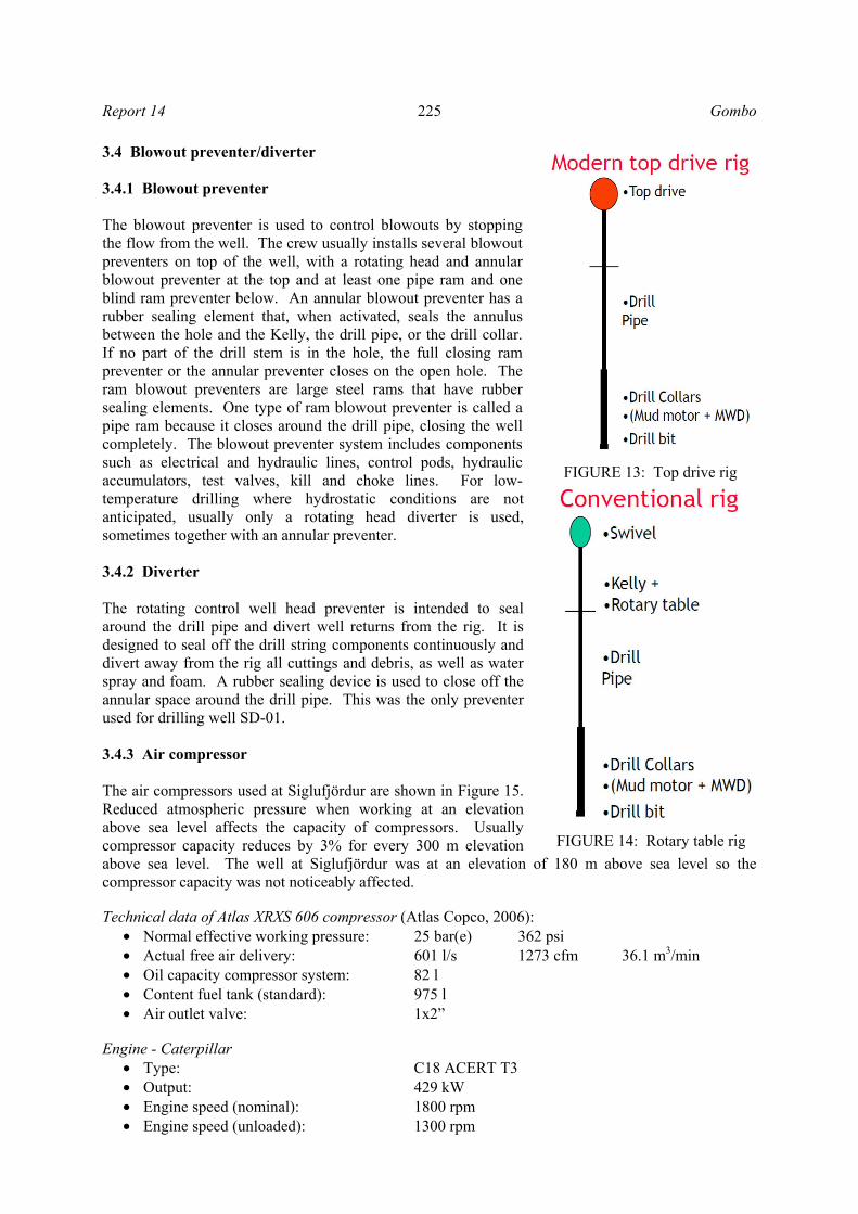
year, the drilling of deep high-temperature wells to more than 500 m became possible. With advancements in technology, the rig industry now offers a selection of electric or hydraulic rigs with different degrees of automation for the handling of drill pipes and casing. The successful completion of a geothermal well on time and with a good safety margin depends on the efficiency of the rig and the level of skill of the rig crew members, in addition to proper planning and coordination of all the pre-drilling activities like civil works, procurement of spare parts and consumables required in the drilling operation. The first step is choosing the right type and size of rig with a good safety margin (Thórhallsson, 2010). The main difference between the top drive rig and the rotary table rig is the position of the drive mechanism. The top drive system is situated on the mast and moves with the drill string up and down along the mast guide. The top drive system torque comes from a hydraulic or electric motor drive. The rotary table drive system is situated on the rig floor. The rotary table drive system is mechanical where the torque is transmitted to a hexagonal pipe called the Kelly, through a chain and a sprocket. Table 2 lists the advantages of using a top drive compared to using a rotary table.
TABLE 2: Top drive vs. rotary table (Thórhallsson, 2010)
Top drive Rotary table This is the preferred type of rig for geothermal drilling due to:
• Efficient bit cooling. • Always connected to drill string – can rotate
at all times to avoid getting stuck. • Can be used for screwing drill pipe and
casings.
This is the “old” type rig which, if not upgraded, has difficulty in getting jobs because:
• It has only intermittent cooling when running in the hole.
• No rotation is possible when pulling out of the hole with the Kelly disengaged.
• Large fill-in can preclude engaging the Kelly. A sketch of a drill string for a rig with top drive is shown in Figure 13, consisting of the top drive motor at the mast which is connected directly to the drill string. The rotary table rig has, on the other hand, a swivel which is connected to the Kelly to provide rotation of the string, shown in Figure 14.
17m
1.5m
2.3m 2.2m
1.5m6.3m
11.5m
18m
1m1m
4.4m
5
42m
15m
0.6m0.7m
0.7m
1.3m2.4m
1.5m2 m
2.4 m 2.1m
4 6 7
8
10
1112
1
23
1514
13
916
17
Report 14 225 Gombo
3.4 Blowout preventer/diverter 3.4.1 Blowout preventer The blowout preventer is used to control blowouts by stopping the flow from the well. The crew usually installs several blowout preventers on top of the well, with a rotating head and annular blowout preventer at the top and at least one pipe ram and one blind ram preventer below. An annular blowout preventer has a rubber sealing element that, when activated, seals the annulus between the hole and the Kelly, the drill pipe, or the drill collar. If no part of the drill stem is in the hole, the full closing ram preventer or the annular preventer closes on the open hole. The ram blowout preventers are large steel rams that have rubber sealing elements. One type of ram blowout preventer is called a pipe ram because it closes around the drill pipe, closing the well completely. The blowout preventer system includes components such as electrical and hydraulic lines, control pods, hydraulic accumulators, test valves, kill and choke lines. For low-temperature drilling where hydrostatic conditions are not anticipated, usually only a rotating head diverter is used, sometimes together with an annular preventer. 3.4.2 Diverter The rotating control well head preventer is intended to seal around the drill pipe and divert well returns from the rig. It is designed to seal off the drill string components continuously and divert away from the rig all cuttings and debris, as well as water spray and foam. A rubber sealing device is used to close off the annular space around the drill pipe. This was the only preventer used for drilling well SD-01. 3.4.3 Air compressor The air compressors used at Siglufjördur are shown in Figure 15. Reduced atmospheric pressure when working at an elevation above sea level affects the capacity of compressors. Usually compressor capacity reduces by 3% for every 300 m elevation above sea level. The well at Siglufjördur was at an elevation of 180 m above sea level so the compressor capacity was not noticeably affected. Technical data of Atlas XRXS 606 compressor (Atlas Copco, 2006):
• Normal effective working pressure: 25 bar(e) 362 psi • Actual free air delivery: 601 l/s 1273 cfm 36.1 m3/min • Oil capacity compressor system: 82 l • Content fuel tank (standard): 975 l • Air outlet valve: 1x2”
Engine - Caterpillar
• Type: C18 ACERT T3 • Output: 429 kW • Engine speed (nominal): 1800 rpm • Engine speed (unloaded): 1300 rpm
FIGURE 13: Top drive rig
FIGURE 14: Rotary table rig

Gombo 226 Report 14 Unit dimensions (overall)
• Length (wagon, toward raised): 5.4 m • Length (skid, support mounted): 4.56 m • Width: 2.25 m • Height (wagon): 2.51 m • Height (skid, support mounted): 2.44 / 2.27 m
Weight (dry)
• Wagon: 7375 kg • Support mounted (option big fuel tank): 6730 / 6860 kg • Skid (option big fuel tank): 6950 / 7080 kg
4. DRILLING PROCEDURE The well‘s temperature and diameter (calliper) were logged on September 4th 2010. The measurements revealed a cavity near bottom and a productive fracture that were not to be cased off. A temporary plug of gravel and sand was thus placed in it, which was then topped with a thin layer of cement before the well was lined with a 10 ¾“ casing on September 5th and 6th to 286 m. Then, a temporary 9⅝“ casing to allow underbalanced drilling was inserted down to 190 m and a diverter placed on top of the well in the period September 7th-10th. After that, conventional rotary drilling started with an 8½“ drill bit on September 11th, which was completed at 702 m depth on September 20th. Logging of the well took place over the period Sept. 23rd - 25th, at the end of drilling. Air compressors were used to achieve underbalanced drilling conditions during drilling of the productive zone, by pumping air on the annulus and water through the drill string. The following measurements were made: temperature measurements, calliper logs, pump step tests, and resistivity, gamma, and NN (neutron-neutron) measurements. In addition, a video camera was lowered down to 580 m and the well in its entirety was surveyed with an acoustic televiewer. Drilling operations went well as no problems were encountered. 4.1 Casing procedure The casing procedure began with transportation where the casing was placed near the drilling rig. The insides of the tubes needed to be cleaned of waste, minimum drift diameter had to be gauged, and the casings made ready for installation. Thereafter, with the assistance of the crane handling system, square steel plates were welded as holders for the casing elevator, 120 cm from the end of the casing. The welding process for the casing joints was completed as described in Section 2.2.1. After casing installation, preparations for cementing started. 4.2 Cementing procedure 4.2.1 General Geothermal well cementing is the process of mixing and displacing a slurry down through the casing and up the annulus behind the casing, where it is allowed to set, thus bonding the casing to the formation. Some additional functions of cementing include:
• Protecting production formation; • Providing support for the casing; • Protecting the casing from corrosion; • Sealing off troublesome zones;
FIGURE 15: Air compressors

Report 14 227 Gombo
• Protecting the borehole in the event of problems. The cement used is Icelandic Portland cement, the same as is used in general concrete construction. The name comes from the solid mixture resembling the rocks quarried on the Isle of Portland, off the coast of England. All cement is manufactured in essentially the same way. Calcareous and argillaceous materials (containing iron and aluminium oxides) are finely ground and mixed in correct proportions, either in a dry condition (dry processing) or with water (water processing). The mixture is then fed into the upper end of a sloping kiln at a uniform rate. The kiln is heated to temperatures from 1430°C to 1650°C (Baker Hughes Inteq, 1995). Casings should be cemented in place with cement slurry. The Portland cement is mixed with water until its density becomes 1.8 g/cm3. During cementing, the density of the slurry should be recorded every 5 minutes with a mud balance. Cementing should continue until the cement slurry reaches the surface on the outside of the casing. It is good practice to keep 1.5-2 times the estimated cement needed for the cementing job at the site (50 or 100% more than the calculated volume between the casing and the formation). It is important that the cement slurry reaches the surface. The unfilled spaces between the casings may need to be filled if the slurry does not surface, or if the cement surface drops. For small cementing jobs and where cement mixing trucks are available, it is possible to use ready-mix trucks of say 7-10 m3 capacity to bring in the slurry and then to pump it with a concrete pump into the well. This is the procedure that was followed at Siglufjördur, as is shown in Figure 16. Once the cement has been pumped, water is used for the displacement of the cement slurry. For that, the rig pump and water tank are used. The volume of water is calculated to put the top of cement about 10 m above the guide shoe; for that, the level in the tanks is measured with a ruler to make sure that the right amount was pumped.
FIGURE 16: Cementing procedure using a ready-mix truck and concrete pump

Gombo 228 Report 14 The cementing head is welded to the top of the casing and is used for cementing the annular space between the casing and the borehole. The cementing head is employed to connect the cement pump to the casing string and provides access for insertion of cementing plugs, if used. First the calculated amount of cement slurry is pumped into the casing head and immediately thereafter a pre-calculated amount of water is pumped behind the cement to displace it. For such small cementing jobs in Iceland, cement rubber plugs are not used; the only cementing hardware installed are a guide shoe on the bottom of the casing and centralizers. 4.3 Logging (temperature and depth) Geothermal logging developed from petroleum logging and relies, to a great extent, on the latter’s experience and development. Most common are down-hole temperature and pressure measurements (T&P) but other geophysical logs are also employed to define the geological structure and the reservoir. The T&P logs are the most common for two reasons. The first, taken during drilling, helps locate loss zones and evaluate the expected productivity of the well by step-rate injection or pumping. The others, done set intervals after drilling, measures the temperature profile during heating up in order to estimate reservoir temperature with depth and the most likely production zones. Then there are geophysical logs that give information on structure, physical properties and the performance of the geothermal system penetrated by the well. Such logs are sometimes not employed for low-temperature wells due to cost. The main purpose of logging is to define (Stefánsson and Steingrímsson, 1990):
• The geological construction of the geothermal field; • The size of the reservoir; • The boundary.
4.3.1 Temperature measurement The down hole temperature was measured on September 3rd 2010 (Figure 17). The water level was at 76 m and the highest temperature 72°C, was logged at 302 m. With air lift pumping, the flow was increased in three stages to 25 l/s. Calliper measure-ments of the hole are shown in Figure 18. Temperature logs made during drilling and at the end are shown in Figure 19. The logs were made during injection, after a stop or during air-lifting (i.e. referring to various stages of the production tests). Based on temperature measurements, it can be concluded that there are two main production zones in the well at 300 and 480 m depth. The temperature difference between them is only 1°C during air-lifting. The vein at 300 m is at 72°C and the one at 480 m at 73°C. The last measurement, which was done 2 hours after air-lifting, shows 1°C higher temperature in both veins. Measurements from September 17th were of the greatest value in showing which veins gave off the water that reaches the surface; an injection FIGURE 17: Temperature profile of well SD-01

Report 14 229 Gombo
was made through the drillstring to the bottom of the well on that date. In those measurements, the veins at 300 and 480 m were, by far, the clearest contributors, although video imaging showed a few active veins between the main ones that did not appear in the temperature measurements. It can be concluded that the veins from 300 to 480 m belong to the same temperature system, a system with water temperatures of slightly less than 75°C. 4.3.2 Geophysical measurements and calliper logging Conventional geophysical measurements were made at the end of the drilling operations, in addition to conducting calliper logging from the top of the well to bottom. Calliper logging The largest wash-out or cavity is below the casing at 286 m down to a little more than 300 m (Figure 20). There is an easy explanation for it, since a 12½“ drill bit was used down to 302 m, before the well was
lined. There are a few other small cavities, the main ones at 335-355, 385-400, 470-485, and 495-510 m depth. Lithological measurements There is a clear correlation between the resistivity and neutron measurements, since the peak of neutron detection is connected with high resistivity deviations, which is explained by the effects of dense rock, i.e. lava layers and/or intrusive layers. Some noteworthy depths in this context are at 324, 357, 414, 433, 490, 557, 619, 629, 648, and 676 m. None of the dense rock detected by the neutron measurements is acidic or semi-acidic, judging from natural gamma radiation. An analysis of natural gamma radiation shows amplitude peaks at five locations in the well: 290, 336, 440, 519, and 657 m. This indicates acidic and/or semi-acidic interlayers (Jóhannesson et al., 2010). FIGURE 19: Geophysical logging of well SD-01
FIGURE 18: Calliper log of well SD-01

Gombo 230 Report 14
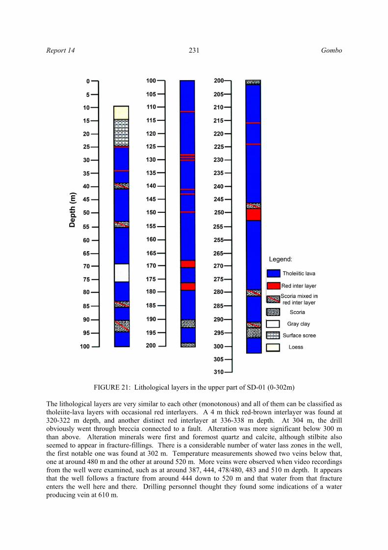
4.3.3 Geological layers (lithology) Well cuttings were analysed on site and the casing depth was decided at 285-287 m. The strata are uniform; all lava layers are tholeiitic with red layers in between and most are thin (Figures 21 and 22). There is little alteration in the well, mostly represented in veins and inclusions in the belonging scoria. Only calcite and quartz were present. At 70-76 m there was a distinct grey clay layer. At the main feed zone at 302 m nothing unusual was seen, no caving filling (inclusions) or vein fillings. It can be assumed that the drill barely reached the aquifer that leads to the water and that the well has yet to go through the aquifer.
FIGURE 20: Lithological and dimensional measurements made after drilling
Report 14 231 Gombo
The lithological layers are very similar to each other (monotonous) and all of them can be classified as tholeiite-lava layers with occasional red interlayers. A 4 m thick red-brown interlayer was found at 320-322 m depth, and another distinct red interlayer at 336-338 m depth. At 304 m, the drill obviously went through breccia connected to a fault. Alteration was more significant below 300 m than above. Alteration minerals were first and foremost quartz and calcite, although stilbite also seemed to appear in fracture-fillings. There is a considerable number of water lass zones in the well, the first notable one was found at 302 m. Temperature measurements showed two veins below that, one at around 480 m and the other at around 520 m. More veins were observed when video recordings from the well were examined, such as at around 387, 444, 478/480, 483 and 510 m depth. It appears that the well follows a fracture from around 444 down to 520 m and that water from that fracture enters the well here and there. Drilling personnel thought they found some indications of a water producing vein at 610 m.
FIGURE 21: Lithological layers in the upper part of SD-01 (0-302m)

Gombo 232 Report 14
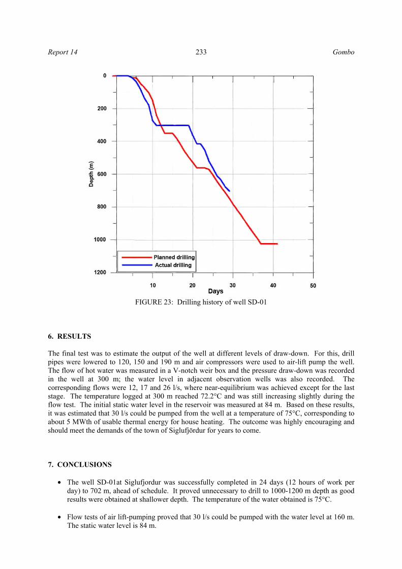
5. DRILLING HISTORY Drilling started on August 23rd, 2010. Figure 23 shows the history of the drilling, as depth vs. days. In the first few days, equipment was transported, placed, connections were adjusted and all was made ready for drilling. According to the plan, the first casing was drilled with a 17½” air hammer on August 26-27; a 13 m hole was drilled for installation of the first casing. Thereafter, the 2 pieces of the casing were welded, each of them with a 6.5 m length and 14” cement shoe. The Portland cement had a density of 1.8 m3. After the cement was pumped, drilling with a 12½” DTH air hammer started. The drilling continued to 94 m and was completed on time. Some of the time, the rate of drilling was 5 m/h, depending on the hardness of the underground. After 5-6 days of drilling, at a depth of 302 m a large los of circulation zone was reached. Employees of ISOR – Iceland GeoSurvey came to make logging measurements and revealed a hot water temperature of 72.2°C degrees at 302 m depth on September 3rd. After logs were taken it was decided to “save” the loss zone at 302 m by temporarily covering it with sand during cementing of the production casing. The work on the 10¾” of production casing was started and continued for 3-4 days. The production casing was installed to 287 m depth. Preparations for cementing and installation of cementing equipment followed. Other important equipment prepared included a mud pump and a water tank (Jóhannesson and Kristinsson, 2010; Jóhannesson et al., 2010).
FIGURE 22: Lithological layers in the lower part of well SD-01 (302-702m)
Report 14 233 Gombo
6. RESULTS The final test was to estimate the output of the well at different levels of draw-down. For this, drill pipes were lowered to 120, 150 and 190 m and air compressors were used to air-lift pump the well. The flow of hot water was measured in a V-notch weir box and the pressure draw-down was recorded in the well at 300 m; the water level in adjacent observation wells was also recorded. The corresponding flows were 12, 17 and 26 l/s, where near-equilibrium was achieved except for the last stage. The temperature logged at 300 m reached 72.2°C and was still increasing slightly during the flow test. The initial static water level in the reservoir was measured at 84 m. Based on these results, it was estimated that 30 l/s could be pumped from the well at a temperature of 75°C, corresponding to about 5 MWth of usable thermal energy for house heating. The outcome was highly encouraging and should meet the demands of the town of Siglufjördur for years to come. 7. CONCLUSIONS
• The well SD-01at Siglufjordur was successfully completed in 24 days (12 hours of work per day) to 702 m, ahead of schedule. It proved unnecessary to drill to 1000-1200 m depth as good results were obtained at shallower depth. The temperature of the water obtained is 75°C.
• Flow tests of air lift-pumping proved that 30 l/s could be pumped with the water level at 160 m.
The static water level is 84 m.
FIGURE 23: Drilling history of well SD-01

Gombo 234 Report 14
ACKNOWLEDGEMENTS I would like to express my gratitude to Dr. Ingvar B. Fridleifsson, director, and Mr. Lúdvík S. Georgsson, deputy director, of the UNU Geothermal Training Programme for giving me the opportunity to participate in this special course. Sincere thanks to Mr. Ingimar Gudni Haraldsson, Ms.Thórhildur Ísberg, Mrs. Dorthe H. Holm and Mr. Markús A.G. Wilde for their useful help during the training period. Many thanks go to Mr. Sverrir Thórhallsson, my supervisor, for his good guidance, for sharing his knowledge and experience and for supervision of this work. My thanks also go to Mr. Steinar Már Thórisson, the rig’s toolpusher, and Mr. Hermann Gudmundsson for their assistance. I also thank RARIK and Jardboranir Ltd. for allowing me to use their data. Special thanks to my parents and my wife Otgonchimeg T. for their spiritual and intellectual support during the six months in Iceland. I want to thank Purevsuren Dorj, Batbayar Tseesuren and Boldbaatar Burentsagaan at the Energy Authority of Mongolia for their support. My thanks also go to my colleagues in the National Renewable Energy Centre of Mongolia. Finally, I would like to thank the entire drilling engineering group for their keen interest in passing their skills to others. Thanks to all UNU-GTP lectures, to the Orkustofnun/ISOR staff, the UNU-GTP Fellows of 2010 and friends for their moral and emotional support during the six months.
REFERENCES Atlas Copco Portable Air compressor, 2006: Technical data. Atlas Copco, Wilrijk, Belgium, website: www.atlascopco.com.
Baker Hughes Inteq, 1995: Drilling engineering workbook, a distributed learning course. Baker Hughes INTEQ, Houston, USA, 410 pp.
Hole, H., 2008: Geothermal well design-casing and wellhead. Petroleum Engineering Summer School, Dubrovnik, Workshop 26, 7 pp.
IADC, 2000: IADC drilling manual, vol II. Technical Toolboxes, Inc., TX, 1463 pp.
Jardboranir, 2010: Technical data. Jardboranir, Ltd, Reykjavík.
Jóhannesson, H., and Kristinsson, S.G., 2010: Drilling of well SD-01 in Skarddalur in Siglujördur, 1st
phase. ÍSOR, Reykjavík, report ÍSOR-10100, (in Icelandic) 11 pp.
Jóhannesson, H., Kristinsson, S.G., Jónasson, H., Tryggvason, H., Egilson, Th., and Ólafsson, M., 2010: Drilling of well SD-01 in Skarddalur in Siglujördur, 2nd phase. ÍSOR, Reykjavík, report ÍSOR-2010/36, (in Icelandic) 69 pp.
RARIK, 2010: Drilling in Skardsdalur in Siglufördur. Bidding and work planning documents. Orkustofnun, Iceland, 53 pp.
Stefánsson, V., and Steingrímsson, B.S., 1990: Geothermal logging I, an introduction to techniques and interpretation, 3rd edition. Orkustofnun, Reykjavík, report OS-80017/JHD-09, 117 pp.
Thórhallsson, S., 2008: Geothermal drilling and well pumps. Papers presented at the Workshop for Decision Makers on Direct Heating Use of Geothermal Recourses in Asia organized by UNU-GTP, TBLRREM and TBGMED, Tianjin, China, 13 pp.
Thórhallsson, S., 2010: Geothermal drilling technology. UNU-GTP, Iceland, unpublished lectures.