A Snapshot of the Drilling and Completio n Practices in High Temperature Geothermal Wells -...
13
Workshop 4: Drilling Cost Effectiveness and Feasibility of High‐Temperature Drilling 2-5 July 2007 Page 1 of 13 A Snapshot of the Drilling and Completion Practices in High Temperature Geothermal Wells in the Philippines SARMIENTO, ZOSIMO F. FEDCO, Muntinlupa City, Philippines [email protected] Abstract Well drilling costs in the Philippines currently account for 66 % of the cost of steamfield development and 33 per cent of the total project cost. D rilling cost is directly influenced by the problems associated with unrecoverable loss of circulation and collapsing formations which hindered drilling progress. Considering its significant impact in the pricing of steam, and the need to make the geothermal electricity price more competitive, geothermal operators in the Philippines continue to search for innovations to test new technologies that would speed up drilling operations. Recent drilling results indicate an emerging and better performance that was previously subsumed to be unpredictable, based on a wide scatter in the Cartesian plot of the total depth (TD) drilled versus duration. Considerations applied in well design, drilling practices and completion technology in the Philippines are discussed in this paper. Downhole logging, to determine static formation temperatures while drilling, aides in setting the production casing at desired temperatures. Right-sizing of casing allows wellbore output optimization and, thus, reduces total well requirements for highly permeable reservoirs. Hydro-fracturing, thermal fracturing and acidizing have been effective in improving production and injection capacities of wells. Under-balanced drilling using aerated mud and water in an under-pressured reservoir significantly improved drilling performance and led to attainment of drilling targets and successful completion of wells. The completion of >2500 meter well in less than 30 days had been ac hieved through the use of po rtable top drive equipment, high performance polycrystalline diamond bits (PCD), high temperature mud motors and implementation of improved drilling practices. 1. Introduction The Philippines remains the second largest producer of geothermal energy in the world with an installed capacity of 2,027 MW. Drilling activities for development of high temperature fields in the country began as part of the government’s exploration program in Tiwi from 1964-1971. As of end 2005, a total of 658 wells had been drilled in support of the geothermal power program (Fi gure 1). 1968 1972 1976 1980 1984 1988 1992 1996 2000 2004 2008 YEAR 0 40 80 120 160 200 240 280 320 360 400 440 480 520 560 600 640 680 C U M U L A T I V E N O . O F W E L L S Figure 1: Annual drilling for high temperature geothermal wells in the Philippines. The country’s geothermal drilling program was launched by initially drilling shallow thermal gradient holes from 120-200 meters; leading to site identification and completion of a discovery well in 1972, and subsequent commitment for commercial development of the Tiwi geothermal field to 330 MW. In 1973, series of shallow exploratory wells were also drilled in Tongonan using a Truck-Mounted Failing Rig up to depths of 268-600 meters (KRTA, 1979). These exploratory wells were later followed by deep drilling which also led to the completion of each discovery well in MakBan in 1974, Tongonan in 1976 and Palinpinon in 1978. Tiwi and MakBan were both operated by Unocal Philippines Inc. (now Chevron Geothermal). All the other fields were discovered in 1980 onwards. Deep drilling in Tiwi and MakBan were conducted utilizing rigs with a capacity of 3,050 meters. In Tongonan, the production wells were initially drilled utilizing Ideco H-525 and Ideco H-725 to total depth of 1100-1990 meters. Geothermal drilling got a boost from the government’s geothermal company (PNOC-Energy Development Corporation) when it acquired new rigs vis-à-vis: National 610, Conemsco D-3, National 370,
-
Upload
adil-aytekin -
Category
Documents
-
view
213 -
download
0
Transcript of A Snapshot of the Drilling and Completio n Practices in High Temperature Geothermal Wells -...

7/26/2019 A Snapshot of the Drilling and Completio n Practices in High Temperature Geothermal Wells - Sarmiento
http://slidepdf.com/reader/full/a-snapshot-of-the-drilling-and-completio-n-practices-in-high-temperature-geothermal 1/13
Workshop 4: Drilling Cost Effectiveness and Feasibility of High‐Temperature Drilling 2-5 July 2007
Page 1 of 13
A Snapshot of the Drilling and Completion Practices in
High Temperature Geothermal Wells in the Philippines
SARMIENTO, ZOSIMO F.
FEDCO, Muntinlupa City, [email protected]
Abstract
Well drilling costs in the Philippines currently accountfor 66 % of the cost of steamfield development and 33
per cent of the total project cost. D rilling cost is directlyinfluenced by the problems associated withunrecoverable loss of circulation and collapsingformations which hindered drilling progress.Considering its significant impact in the pricing ofsteam, and the need to make the geothermal electricity
price more competitive, geothermal operators in thePhilippines continue to search for innovations to testnew technologies that would speed up drillingoperations. Recent drilling results indicate an emergingand better performance that was previously subsumedto be unpredictable, based on a wide scatter in theCartesian plot of the total depth (TD) drilled versusduration.
Considerations applied in well design, drilling practicesand completion technology in the Philippines arediscussed in this paper. Downhole logging, to determinestatic formation temperatures while drilling, aides insetting the production casing at desired temperatures.Right-sizing of casing allows wellbore outputoptimization and, thus, reduces total well requirementsfor highly permeable reservoirs. Hydro-fracturing,thermal fracturing and acidizing have been effective inimproving production and injection capacities of wells.Under-balanced drilling using aerated mud and water inan under-pressured reservoir significantly improveddrilling performance and led to attainment of drillingtargets and successful completion of wells. Thecompletion of >2500 meter well in less than 30 dayshad been achieved through the use of portable top drive
equipment, high performance polycrystalline diamond bits (PCD), high temperature mud motors andimplementation of improved drilling practices.
1. Introduction
The Philippines remains the second largest producerof geothermal energy in the world with an installed
capacity of 2,027 MW. Drilling activities fordevelopment of high temperature fields in the country
began as part of the government’s exploration programin Tiwi from 1964-1971. As of end 2005, a total of 658wells had been drilled in support of the geothermal
power program (Fi gure 1).
1968 1972 1976 1980 1984 1988 1992 1996 2000 2004 2008
YEAR
0
40
80
120
160
200
240
280320
360
400
440
480
520
560
600
640
680
C U M U L A T I V E
N O .
O F W E L L S
Figure 1: Annual drilling for high temperature
geothermal wells in the Philippines.
The country’s geothermal drilling program waslaunched by initially drilling shallow thermal gradientholes from 120-200 meters; leading to site identificationand completion of a discovery well in 1972, andsubsequent commitment for commercial developmentof the Tiwi geothermal field to 330 MW.
In 1973, series of shallow exploratory wells were alsodrilled in Tongonan using a Truck-Mounted Failing Rigup to depths of 268-600 meters (KRTA, 1979). Theseexploratory wells were later followed by deep drillingwhich also led to the completion of each discovery wellin MakBan in 1974, Tongonan in 1976 and Palinpinonin 1978. Tiwi and MakBan were both operated byUnocal Philippines Inc. (now Chevron Geothermal). Allthe other fields were discovered in 1980 onwards. Deepdrilling in Tiwi and MakBan were conducted utilizingrigs with a capacity of 3,050 meters.
In Tongonan, the production wells were initially drilledutilizing Ideco H-525 and Ideco H-725 to total depth of1100-1990 meters. Geothermal drilling got a boost fromthe government’s geothermal company (PNOC-EnergyDevelopment Corporation) when it acquired new rigsvis-à-vis: National 610, Conemsco D-3, National 370,

7/26/2019 A Snapshot of the Drilling and Completio n Practices in High Temperature Geothermal Wells - Sarmiento
http://slidepdf.com/reader/full/a-snapshot-of-the-drilling-and-completio-n-practices-in-high-temperature-geothermal 2/13
Workshop 4: Drilling Cost Effectiveness and Feasibility of High‐Temperature Drilling 2-5 July 2007
Page 2 of 13
Ideco-E2100 and Romanian F 200. These rigs hadcapacities ranging from 2,100 to 6,400 meters. Figure 2shows the 288 and 370 drilled respectively for Unocaland PNOC-EDC since 1972.
1968 1972 1976 1980 1984 1988 1992 1996 2000 2004 2008
YEAR
0
4
8
12
16
20
24
28
32
36
40
44
48
52
56
60
N O .
O F W E L L S D R I L L E D
WELL DISTRIBUTIONPNOC EDC
CHEVRON GEOTHERMAL
Figure 2: Well drilling distribution by two steamfield
operators in the Philippines.
Directional drilling in the Philippines started in 1978 inTiwi and MakBan. In view of the very steep topographyand to overcome the constraints in the limited numberof production and reinjection pads that could beconstructed, PNOC EDC adopted this technique in 1980in Palinpinon. The Palinpinon case serves as a modelfor compact field development, where environmentalimpact is minimized due to minimal surfaceexcavations. However, this strategy resulted in
additional drilling problems and remarkable increase indrilling cost compared with conventional verticaldrilling. For Tiwi and MakBan, vertical wells withaverage depth of 1,525 meters were completed from 30-40 days with somewhat longer duration for directionalwells (Horton et al., 1981). More recent wells drilled asmake-up wells in MakBan were drilled much deeperthan 2845 meters, with the deepest reaching 3,425meters including a well with forked-completion (Gollaet al, 2006; Southon, 2003). However, these wells havenow been drilled in almost the same period as theearlier wells with the use of latest rig equipmentincluding portable top drive system in rotating the drillstring, in lieu of Kelly Rotary Table; downhole motors,PCD bits, aerated drilling and implementation of moreimproved drilling practices.
This paper draws on some of the tests and practicesapplied in achieving the drilling objectives and
improving the results in high temperature geothermalfields in the Philippines. The techniques to be describedinclude some of the methods used in setting the
production casing, the drilling difficulties typicallyencountered in Philippine geothermal fields and thestrategies and stimulation methods adopted. The drillingcost and the overall drilling performance in comparison
with international drilling data are also presented. Adetailed presentation on the key drivers of the drilling performance in the Philippines could be referred toanother presentation by Abanes (2007).
2. Casing Design Considerations
Several papers and codes had been published dealingwith various parameters in designing casing for hightemperature geothermal wells: Chillingar and Rieke(1962), Dench (1970), Karlsson (1978), Nicholson(1984), New Zealand Code (1991) and the API (1989).Well casing design in the Philippines subscribes to theabove references to ensure the integrity of thecompleted wells. Thorhallsson et al (2003) alsodiscussed in detail the bases of their design in drillingfor supercritical fluids that are in excess of 375 °C.
Figure 3 shows the typical hole-sizes and casing stringconfiguration adopted in high temperature geothermalwell drilling in the Philippines. Of particular interest isthe successful drilling completion of a forked-hole inMakBan geothermal field by Unocal Philippines Inc.
More recent wells in the Philippines were drilled with10-3/4” and 8-5/8” instead of the 9-5/8” and the 7-5/8”casing-liner combination (Southon, 2003).
2.1 Production Casing Setting Depth
Geothermal reservoirs in the Philippines are typicallywater-dominated, under-pressured and usuallyencountered at 800 meters ASL, with the highest wellscollared in Mindanao from 1200-1600 meters ASL.Most of the wells drilled in this terrain stand with waterlevel up to 1000 meters below the surface. As such,there is inherent difficulty in initiating the well’sdischarge because of large pressure drops the fluidshave to overcome in flowing to the surface. These
reservoir features, aside from the safety of the well andits structural targets, dictate the setting depth of the
production casing.
In drilling for oil and gas wells, all the casings arecemented and perforations are conducted opposite the
payzones for production. In comparison, geothermalwells are completed with open-holes run with slotted or
perforated liners from the production casing shoe tototal depth (TD). Such difference in design requires thesetting depth of production casing to isolate the top ofthe reservoir from overlying cold aquifers, gas-richfluids or acid condensates so that the wells could beused commercially. For production wells, it has to be

7/26/2019 A Snapshot of the Drilling and Completio n Practices in High Temperature Geothermal Wells - Sarmiento
http://slidepdf.com/reader/full/a-snapshot-of-the-drilling-and-completio-n-practices-in-high-temperature-geothermal 3/13
Workshop 4: Drilling Cost Effectiveness and Feasibility of High‐Temperature Drilling 2-5 July 2007
set at a minimum temperature of 220°C to successfully
initiate the fluid flow of the wells. Besides, geothermalfluids with enthalpy lower than the feed zone
temperature of 220°C are more suitable for direct heat
utilization than for power generation.
BIG HOLE COMPLETION
Directional (Double Liner)Directional ( Single Liner)
SCS 22 - 24” 50 - 150 50
500
1250
1800
450 - 500
2500 - 2800 2400
1400 - 2300
ACS 22” 18 5/8”
26”
PCS 171/2”1 3 3/8”
Prod.
Prod.
125/8” 9
7
5/8”
5/8”
Liner1
Liner2
CSG HoleSize Depth (m) Depth (m)
CsgSize
SCS 26” 50 - 150
250 - 600
600 - 900
1400-2300
ACS 17-1/2”
PCS
HoleSize
Depth (m) Depth (m)
Vertical Hole
STANDARD HOLE COMPLETION
Prod.Liner
90 - 100 95
392
932
230 - 350
800 - 1800
2500 - 3300
Directional Forked Hole
18-5/8”
13-3/8”
9-5/8”
7” or7-5/8”
12-1/4”
8-
1/2”7” Perf.
SidetrackedLiner
7” Perf.ParentLiner
CSGCsng.
SizeDepth )m)
Figure 3: Typical hole and casing design in the Philippines
Injectors also require a minimum temperature limit of
220°C below the shoe to ascertain that the shallowest
open zone in the well has temperature higher than the
usual injection temperatures of 165-185°C. This
injection temperature range is maintained to minimize
silica deposition in the wells and thus slow down loss ofinjection capacity.
Based on the temperature distribution in a fully
developed geothermal field, the 220°C setting depth is
easily determined. However, this information does not
exist in newly developed and exploration areas. Thetechniques, which are described below, are therefore
used in approximating the setting depth in conjunctionwith the projected target intersection of the structural
faults.
2.1.1 Boiling Point for Depth Curve
The equation of the curve for boiling point with depth
(BPD) in a geothermal well satisfies a preliminary
prediction of subsurface temperature in exploration
areas to project the setting of the casing shoe depth.
This approximation enables the drilling engineer to plan
the total number of drill strings, casings, cement and
other consumables prior to drilling. This technique
makes use of the elevation of a boiling chloride hot
springs located in the vicinity of the wells to be drilled.The elevation is used to approximate the existing water
table, and serves as the datum level to extrapolate the220°C from the BPD curve for the programmed well.
2.1.2 Static Formation Temperature Tests (SFTT)
SFTT is a temperature recovery measurement
conducted while drilling is stopped at a designateddepth in the hole. The test is run after maintaining full
returns of circulation to the surface. The objective of the
test is to establish the 220°C depth or any temperature
that may be used for decision making while drilling the
hole. The predicted temperature is extrapolated from the
results of a single test or series of measurements.
The SFTT result is used to confirm the predicted resultobtained from the use of the BPD curve. In designing
the succeeding exploratory wells, data could be used
without waiting for three months for the well to recover
from drilling.
Several methods had been developed about this subject
that began in the oil and gas industry (Edwardson et al.,1962; Raymond, 1969; Dowdle, 1975). Messer (1976)
presented a paper on determining static temperatures
using dimensionless Horner type curves of temperature
recovery versus circulating time during drilling
operations. Roux et al., (1979) solved the differential
equation using the Horner type temperature build-up
plot that provides a correction factor to address the non-
linearity of the build-up curve. Later, Brennand (1997)developed a simple and quick method for the same
basic equation without a correction factor by plotting
observed temperatures against 1/ (Δt + 0.785tc) as
shown in Figure 4.
Figure 4: Plot of the downhole temperature used in
predicting stable formation temperatures while drilling
(After Sarmiento, 1993).
The constant (.785) was empirically derived from
various tests conducted in the Philippines while the tc
7/26/2019 A Snapshot of the Drilling and Completio n Practices in High Temperature Geothermal Wells - Sarmiento
http://slidepdf.com/reader/full/a-snapshot-of-the-drilling-and-completio-n-practices-in-high-temperature-geothermal 4/13
Workshop 4: Drilling Cost Effectiveness and Feasibility of High‐Temperature Drilling 2-5 July 2007
Page 4 of 13
represents the total circulation time. The total durationof the test, including the pull-out and run-in of the drillstrings for circulation is about 12 hours. When an e-linetemperature tool is used, the tests could be shortened by3 hours because data analysis could be done in parallelwith the measurements
The SFTT results in the Philippines using the Brennandmethod have been found to be within ±5°C, enough to be used as a basis to accurately set the casing shoe forexploratory wells. The results further suggest that only15% of the predictions deviated by >15°C frommeasured data (Sarmiento, 1993).
More SFTTs are conducted when confronted withdecisions to pre-terminate drilling if (i) sufficient
production temperatures (at least 270°C) in the well has been achieved and (ii) the well is at risk and lowertemperatures or reversals are inferred for the remaining
portion of the hole.
2.1.3 Circulating Temperature Projection
Some of the main functions of drilling fluids areassociated with balancing formation pressures andmaintaining formation stability. Other functions ofdrilling fluid are for cooling of the hole and deploymentof downhole tools like mud motors, drilling jars,logging tools and MWD at possibly longer period. Agood mud also keeps the cuttings in suspension until itis brought to the surface. It prevents the cuttings fromsticking to the bits or collars which are the main causesof stuck-pipes. These functions could be adverselyaffected by high temperatures encountered ingeothermal wells, and requires monitoring of theflowline and bottomhole circulation temperatures (bhct )so that mud conditioning could be done while drilling.
Drilling practices in the Philippines make use of asimple correlation that exists between the bottomholecirculating temperature (bhct ) and flowline outlettemperature ( f out ), where bhct is 1.3 times the value of
f out . The temperature differential between the inlet ( f in)and f out temperatures is usually maintained at 5-10°C. F out temperature reaches as high as 90°C for hightemperature areas, requiring introduction of newly
prepared mud mixtures. The results of these flowlinetemperatures are further checked by using temperaturestickers attached to downhole motors and other tools.
2.1.4 Thermal Simulators
The application of monitoring the flowline temperaturescould be extended in predicting downhole static or
equilibrium temperatures through the use of thermalsimulators. This method was also originally applied inthe oil and gas industry, and found applications withsome modifications in geothermal well evaluation. Hefu(2000) showed the results of two wells in Krafla withclose agreement between the calculated and measured
formation temperatures using STAR, developed inOrkustofnun, Iceland and GEOTEMP2 by Mitchell(1982). Stable formation temperature predictions fromEspinosa et al. (2000) also demonstrated a goodagreement to the measured downhole temperatures byusing TEMPLOP1V.2 - thermal simulator for drillingmud, and GEOMIST - for air-water mixtures. If the
same accurate results from the thermal simulators could be obtained, a considerable savings equivalent to aminimum of 27 hours in drilling time per well could begained by not running the SFTT.
2.2 Casing Sizes
2.2.1 Output Optimization
The results of a study dealing with the feasibility ofdrilling big holes were discussed by Sta Ana et al.(1989). The study was conducted to evaluate theincrease in well output and reduction in the totalnumber of wells to be drilled in a development project.The result of the study indicated that a significantincrease in well output could be achieved for wells withvery high permeability.
Later, big-hole completion was also used to justify theconstruction of production pads at higher elevations tominimize pressure drops, instead of reachinginaccessible flat and low lying areas.
Large hole-completion is adopted for wells where theoutput are found to be wellbore controlled, i.e., the totalmass flow rates are controlled by the size of the well,and is increasing with declining WHP.
0 0.5 1 1.5 2 2.5 3 3.5 4 4.5 5 5.5 6
WELLHEAD PRESSURE (MPag)
0
10
20
30
40
50
60
70
80
90
100
110
120
130
140
150
M A S S F L O W ( k
g / s )
OUTPUT COMPARISONFORMATION CONTROLLED
OK-6 STD. COMPLETION
OK6 BIG HOLE PREDICTION
WELL 212 STD. COMPLETION
W212 BIG HOLE COMPLETION
Figure 5: Output comparison for high and medium
enthalpy wells in the Philippines with standard and big
hole- completion (After Sarmiento. 1993)
This discharge characteristic is illustrated in Figure 5. Awell is run with regular casing combination, when the

7/26/2019 A Snapshot of the Drilling and Completio n Practices in High Temperature Geothermal Wells - Sarmiento
http://slidepdf.com/reader/full/a-snapshot-of-the-drilling-and-completio-n-practices-in-high-temperature-geothermal 5/13
Workshop 4: Drilling Cost Effectiveness and Feasibility of High‐Temperature Drilling 2-5 July 2007
Page 5 of 13
mass flow rate has little change or would remainconstant with change in WHP, also described as
formation controlled .
By simulating the effects of size variation on the casingof high temperature wells, a 30-60 % increase in wells’output was derived by shifting to big-hole completion.
Only 38% increase in output is needed to justify designchange. Moreover, as much as 250% improvement inoutput has been achieved in the actual drilling results(Sta Ana et al., 1997). Figure 6 shows the relativecomparison in cost of drilling big and standard holes.
A total reduction of 19 wells, out of the total 49 wellsinitially programmed to supply field requirement, wasachieved in Leyte for its 600 MWe expansion program.This reduction in total number of wells translated into asavings of USD 38 million, based on a USD 2.1 million
per well cost.
0 400 800 1200 1600 2000 2400 2800 3200
MEASURED DEPTH (meters)
0
0.4
0.8
1.2
1.6
2
2.4
2.8
3.2
3.6
4
4.44.8
5.2
D R I L L I N G C O S T ( U S $ M I L L I O N )
DRILLING COST COMPARISON
STANDARD HOLE (1995-1996)BIG HOLE (1995-1996)
Figure 6: Comparison of drilling cost between big holeand standard completion in Leyte wells adjusted at
2006 level (From Sta Ana et al., 1997.)
Additional savings are also achieved with the reductionin well numbers associated with the material and spacerequirements for the construction of production andreinjection pads, fluid collection and disposal system
and impact to environment. Furthermore, early
commissioning date is also attained and thus earlyreturn on investment.
3. Drilling Problems
3.1 Big-hole design
Aside from optimizing well output, big-hole completionwas also adopted as a drilling strategy to drill up to3000 meters in areas that are saddled with unstable orcollapsing formation. Talens et al., (1997) discussed the
challenges faced in completing the drilling campaignfor the development of the 180 MWe MahanagdongField in Tongonan, Leyte. Using the standard-holecompletion, persistent drilling problems wereencountered in 14 wells leading to failures in attainingtarget depths and missing intersection on 56 % of thetargeted geologic structures; and thus lesser output per
well.
The problems consist of the inability to penetrate morethan one permeable zone after encountering a total losscirculation (TLC) from the first loss zone. Total losscirculation (TLC) is a common phenomenon ingeothermal drilling that occurs when massive fracturesand faults are intersected. To avoid damaging the
payzone and prevent an enormous volume of mud to belost, drilling shifts to water in what is known as blinddrilling . Drilling mud fluids are nevertheless regularlyslugged to keep the cuttings from settling to thedownhole assembly and bits. While blind drilling,wellbore instability is frequently encountered because“weighting-up” to stabilize collapsing formation is not
possible. Similarly, the risk of backflow of cutt ings intothe hole increases during blind drilling, uponintersection of another loss zone at the bottom, andwhen the first loss zone has a very low cuttingsacceptance capacity. These features increase the riskfor occurrence of stuck-up pipes.
To overcome these problems, a big-hole completion(Figure 3) with two liner system using 13-3/8” casingand 9-5/8”blank liner on top of the 7-5/8” liners wasimplemented in drilling for the balance ofMahanagdong wells.
By casing off the upper loss zone through big-holecompletion, full circulation was regained and potentialcollapsing formation was isolated while drilling downto the second loss zone. Moreover, the backflow ofcuttings was arrested at least until the last targeted losszone is intersected.
Table 1 summarizes the drilling performance of wellsthat were classified in four categories.
On type C wells, 5 were drilled with big-hole
completions using the double-liner system of 9-5/8” and7-5/8” diameters enabling the attainment of all drillingand geological objectives. These wells were drilled at afaster rate and deeper than those with standard
completion (D). Drilling with this design was faster by11-21 days than the standard completion. Moreover,
perforation of the 9-5/8” casing could be conducted totap the brine and steam from the cased-off permeable
section if production from the 8-1/2” hole isinsufficient.
The same technique was adopted in some wells previously drill ed with similar problems, but smaller 4”slotted liners were used at the bottom (Southon, 1994).

7/26/2019 A Snapshot of the Drilling and Completio n Practices in High Temperature Geothermal Wells - Sarmiento
http://slidepdf.com/reader/full/a-snapshot-of-the-drilling-and-completio-n-practices-in-high-temperature-geothermal 6/13
Workshop 4: Drilling Cost Effectiveness and Feasibility of High‐Temperature Drilling 2-5 July 2007
Page 6 of 13
This configuration was, however, not pursued becauseresults from subsequent productions from this type ofcompletion did not yield significant contribution fromthe slim-hole portion of many holes.
Table 1: Drilling performance summary from the
Mahanagdong Sector in the Philippines (After Talens et
al., 1997) Well
Type
S/B
Hole
T/I
Struc-tures
Prog.
Depth
Total
Depth
Days
Drilled
Drift
Angle
A 2/2 2/2 2300 2400 69.5 -
B 8/1 3.3/3 2396 2482 75.2 40
C 6/5 2. 5/2.5 2495 2414 64.4 29
D 13/1 3.6/2 2595 2155 85 35
A: Vertical, B: Minimal Losses, C: Attained Geo. Obj.,D: Failed to Attain Geo. Obj., S: Standard Hole, B: Big Hole, T:Target, I: Intersected
3.2 Polymer as Drilling Fluid
Another drilling problem common in the Philippines isthe swelling of clays frequently encountered at the topzone of the reservoir. This happens when the clayeyformation is exposed to the water-laden drilling fluidsin 5-7 days. As the clay swells, the formation collapses.A high temperature liquid polymer (.08 liter/gallon of
water, funnel viscosity=28 spq), was tried in drillingone well to 2900 meters to avoid this problem, as wellas to maintain good hole cleaning during TLC and toavoid mud damage to permeability caused by regularslugs of mud. The dosage rate was increased to .46liter/gallon water, (funnel viscosity of 40-42 spq), whena massive circulation was encountered in the open-hole
section of the well just above the TD. The use of thisliquid polymer had been satisfactory because the wellwas drilled without obstruction down to TD of 2900meters. The high consumption and cost of the polymerconstrained further trials on additional wells.
3.3 Under Balanced Air Drilling
Reservoir depletion due to continuous production hasresulted in significant pressure drawdown andexpansion of the two-phase zone in maturing fields inthe Philippines. During drilling of infill wells, the mudhydrostatic pressure exceeds the reservoir pressure,especially at the top zone where steam easily condense
and collapse. This transition in the fluid properties ofthe reservoir causes drilling fluids to be lost to theformation, especially when penetrating the highlyfractured andesitic lavas and pyroclastics in thereservoir, and has added complexities to the inherently
problematic drilling operations in the Philippines.Jumawan et al (2006) and Herras and Jara (2006)described the performance of conventional drilling mudand aerated fluids while drilling infill wells at the centerof the under-pressured reservoir of Tongonan.
3.3.1 Circulation Losses while Air Drilling
Two wells were drilled with the same target in the samesector where there is significant pressure drawdown;one with conventional drilling mud fluids and thesecond well with aerated mud/water at under-balanceddrilling condition. The objectives of the two wells were
to drill up to 2,900 meters to tap the high temperaturefluids at depth. The casing shoe had to be set from1,600-1,900 meters to avoid producing from thedepleted top zone. All losses were required to be
plugged.
Unrecoverable losses and blind drilling led to the premature completion of the first well while drillingwith conventional mud fluids. Mud fluids and cuttingsmigrated swiftly to adjacent wells causing surges towater levels in separators, and subsequent increase intotal suspended solids in steam. The turbines requiredtemporary shutdown until remedial action to reduce theTSS was put in place. Some wells collapsed due tosubstantial cooling, and drilling could not progress untilwell was prematurely TDed.
The major impact of these problems was the reductionin total output of the field and forced-acidizing of
production wells that had communicated and had beendamaged by mud while drilling.
Learning from this experience, subsequent drilling inthe same sector was conducted with aerated drilling,and full circulation returns were recovered by adjustingthe air-water and air mud ratios. Steam influx and wellkicks from the top zones were allowed but at conditionswhere temperatures would not go beyond the limitationof the rubber O-rings of the BOP stack (Jumawan et al.,2006). Good hole cleaning due to maintenance of fullcirculation led to completion of these wells at muchdeeper levels than when they were drilled withconventional mud systems. One well was completed to2,900 meters with air drilling applied at the productioncasing interval only, and mud as the drilling fluids fromthe 9-5/8” shoe to bottom hole.
4. Stimulation Methods
Stimulation procedures to enhance reservoir permeability are conducted immediately after welldrilling completion or subsequently after the wellrecovery. It may consists of hydro-fracturing, thermal
fracturing and acidizing. Hydro-fracturing and thermalfracturing create or enlarge fractures that connect with
pre-existing fractures within or farther away from thewellbore. Acidizing dissolves the mud that blocks the
sandface fractures. Wells also require some stimulationto initiate flow to the surface. These methods involveair compression, gas lift, and two-phase stimulation by
boiler or by hook-up from production wells. Theavailability of the coil tubing unit (CTU) and rig allowsthe use of nitrogen gas or air to stimulate even the most

7/26/2019 A Snapshot of the Drilling and Completio n Practices in High Temperature Geothermal Wells - Sarmiento
http://slidepdf.com/reader/full/a-snapshot-of-the-drilling-and-completio-n-practices-in-high-temperature-geothermal 7/13
Workshop 4: Drilling Cost Effectiveness and Feasibility of High‐Temperature Drilling 2-5 July 2007
Page 7 of 13
reluctant wells through lifting of the cold fluid columnto the surface, until the well is emptied and the wellkicks by itself. This method is also used to clear thewell with mud that settled at the bottom including thosethat are blocking the permeable zones.
4.1 Hydro-fracturing
Hydro-fracturing usually involves injecting water athigh wellhead pumping pressures, and in some casesentail the use of proppants to wedge the fractures
propagated during the operation.
Figure 7 shows the results of a hydro-fracturing job forthe first well (LB-1D) drilled in the Mt. Labogeothermal prospect in Southern Luzon, Philippines(Sarmiento, 1993). Hydro-fracturing was conductedduring the completion test after high WHP wasmeasured while pumping at minimal flow; a conditionsuggesting the tightness or the lack of permeability ofthe well. The operation consisted of injecting water atmaximum pump rate of 30 l/s for 24 hours until theWHP turned into vacuum condition.
A well is at vacuum condition when it is sucking morefluids than what the pump could deliver. The finalinjectivity index of the well after the hydrofrac was 25l/s- MPag at vacuum condition against 45 l/s-MPagwith a positive WHP before the hydrofrac. Moreover, a
pressure difference of >5 MPa was measured before andduring the hydrofrac operation, suggesting the openingand enlargement of fractures. The well sustained acommercial output by using the CTU for gas-liftoperation.
16 18 20 22 24
DOWNHOLE PRESSURE (MPa)
10
20
30
40
50
F L O W R A T E ( l / s )
Injectivity Index= 46 l/s-Mpa(With Positive WellheadPressure while Pumping)
Injectivity Index= 25 l/s-MPag At Vaccuum Well Head Pressure
Figure 7: Injectivity Index comparison of LB-1D before
and after a hydro-fracturing job (After Sarmiento,1993).
The above result is typical of many wells successfullystimulated by hydro-fracturing in the Philippines. Otherinjectors that were earlier diagnosed to be tight during
drilling because of the lack of total or partial loss ofcirculation (PLC) had been highly stimulated afterhydro-fracturing, thereby eliminating drilling ofadditional wells for replacement.
4.1.1. Proppants
One reinjection well displayed a positive result withhydro-fracturing using proppants until it was put on lineas an injector. The proppants used were normal gradedsilica sand which is liable for dissolution in hot water.Clotworthy (1997) suggested that the apparent gain ininjectivity might have been caused by the opening ofthe zone below the shoe. However, it was also possiblethat the loss in capacity after a short period of time wasdue to silica scale build-up in the proppant-initiatedfractures. The case may have been different if this wastried in a production well, especially in a dry steam wellwhere the chance of scaling due to silica is small.
Two other wells had been subjected to hydro-fracturingwith proppants but no improvements were gained.These wells were drilled along the western boundary ofthe Tongonan field where the formations are found to
be mineralized with clay.
4.2 Thermal Fracturing
Thermal fracturing is done by alternately pumpingwater and allowing the well to recover by heat-up, andcreating thermal shocks that are capable of producingcracks into the formation. It can also be demonstrated
by injecting cold fluids in a relatively hotter formationto create or enlarge fractures during the contraction ofthe rock matrix contracted. Example of this method inthe Philippines is the low temperature condensateinjection being implemented to comply with the
prescribed zero-waste disposal in the EnvironmentalCompliance Certificate of the project. A condensateinjection well in Mindanao I after being used for morethan 3 years was tested to have increased its injectivityfrom 10 to 12.3 liters/s-MPag with a correspondingdrop in downhole pressures. The calculated kh alsoincreased from .2dm to 4.88 md.
4.3 Acidizing
Acidizing consists of pumping HCl and HF mixtures totreat the formation of mud damage resulting fromdrilling operations. Because of the expense involved,
this method is usually delayed during the well recoveryas an ultimate solution to enhance well output.However, in some cases where the urgency for steamsupply requires immediate acid treatment, then it
becomes part of the drilling program (Yglopaz et al.,2000).
4.3.1 Output Change
Since 1993, acid treatment has been widely used in the

7/26/2019 A Snapshot of the Drilling and Completio n Practices in High Temperature Geothermal Wells - Sarmiento
http://slidepdf.com/reader/full/a-snapshot-of-the-drilling-and-completio-n-practices-in-high-temperature-geothermal 8/13
Workshop 4: Drilling Cost Effectiveness and Feasibility of High‐Temperature Drilling 2-5 July 2007
Page 8 of 13
Philippines to enhance production and injectioncapacities of geothermal wells. Sarmiento (1993) firstshowed that mechanical workover or clearing of scalesin reinjection wells should not be confined only withinthe wellbore, and must extend beyond the sandface torecover lost injection capacity. This finding led to thetrial and successful acidizing jobs in Palinpinon
involving one production well (PN-32D) that wasdamaged by mud during drilling, and one reinjectionwell (PN-2RD) that had suffered a declining injectioncapacity.
To date, the success of this stimulation method isrepeated in the Philippines and around the world onmany wells that are suffering from mud damage andmineral deposition. Buning et al., (1995) updated theacidizing results from 1993-1995 and reportedsignificant improvement in the capacities of 9 out of tenwells initially acidized in the Philippines. Other resultsare reported in Malate et al., (1997), Yglopaz et al.,(2000) and Sarmiento (2000). Table 2 summarizes theresults of acidizing jobs in the Philippines since thetrials in the first two wells. A minimum 29 % with amaximum 911 % increase in output/injection capacitieshad been obtained from various acid treatmentoperations.
Table 2: Summary of acid treatment operations in the Philippines (After Sarmiento, 2000) Well Name Injection Capacity/Output
(kg/s) or (MWe)Improvement (%)
PRODUCTION
WELLS
(MWe)
(1) (2) (3)
PN-32D 2.2 2.2 4.1 86
110D 4.1 4.1 12.4 202
MG-29D ND ND 7.3
MG-27D NC NC 8.9
MG-30D 4.3 4.3 14.7 242MG-31D ND ND 19.6
MG-28D 5.9 5.9 8.2 39
MG-24D 3.8 3.8 5.6 47
MG-26D untested untested 2.4
OP-5DA 1.5 1.5 4.1 173
OP-3D 2.6 2.6 5.5 110
REINJEC-TION WELLS (kg/s)
PN-2RD 60 40 187 367
2R4D 90 *18 *182 911
TC-2RD 146 57 97 70
1R10 35 *30 *48 60
4R-7D 70 36 91 153
4R12D 149 149 264 77
KL-2RD 56 134 139
KL-1RD 103 133 29
OP-1RD 30 70 133OP-2RD 70 137 96
TIGHT WELLS kg/s
MG8D 10 22 120
MN-1 20 39 95
Notes: 1: Before Drill Out, 2: Pre-Acidizing 3: Post Acidizing* Calculated Max. Results
4.3.2 Thermal Recovery Of significant results shown by acid treatment was therelative rapid recovery of temperatures on heavily mud-
damaged wells (2,700-42,000 barrels of mud lost)compared with the period after drilling completion.Wells damaged by mud takes up to more than 5 weeksto thermally recover. On the other hand, wells could
be ready for discharge within 5 days to 3 weeks afteracid treatment. Post acid treatment of wells inMahanagdong Production Field in Leyte resulted in
significant output improvement and immediateavailability of capacity from 14-64 MW for thescheduled plant commissioning; and thus averting a
penalty situation for PNOC Energy DevelopmentCorporation due to insufficient steam (Yglopaz et al.,2000).
Acid treatment of geothermal wells has been proven to be effective also in dissolving calcite deposits oppositethe flash point in production wells. The same treatmentis found to be effective for wells that have been cased-off and later perforated for production.
4.3.3 Quantifying Improvements by Acidizing
One of the most significant advances in the applicationof acidizing for well stimulation in the Philippines isthe development of a method that predicts the mostlikely improvement of a well if it undergoes acidtreatment. Aleman and Clothworthy (1996) described itin detail.
10 12 14 16 18
DOWNHOLE PRESSURE (MPag)
0
5
10
15
20
25
30
35
40
P U M P R A T E
( l / s )
SKIN PRESSURE
MEASUREDZERO FLOW
PRESSURE(12 MPa)
EXTRAPOLATEDZERO FLOWPRESSURE
(14 MPag)
INJECTIVITY DATA COMPARISON
Pre-Acid Comp Test
Post-Acid Com. Test
Figure 9: Typical injectivity plot for comparison on an
acidizing job for damaged wells
In general, the skin pressure caused by the mud cake ormud damage in the well’s sandface refers to thedifference between the extrapolated measured pressureat zero flow rate during pumping and the stable
pressure measured during the recovery period at thesame depth where the test was conducted. Thistechnique is illustrated in Figure 9 by plotting the pumprates versus the measured pressures obtained during thewell completion test.
7/26/2019 A Snapshot of the Drilling and Completio n Practices in High Temperature Geothermal Wells - Sarmiento
http://slidepdf.com/reader/full/a-snapshot-of-the-drilling-and-completio-n-practices-in-high-temperature-geothermal 9/13
Workshop 4: Drilling Cost Effectiveness and Feasibility of High‐Temperature Drilling 2-5 July 2007
Page 9 of 13
The minimum amount of additional flow that could beinduced by acidizing can be estimated by multiplyingthe injectivity index of the well and the skin pressure asshown in the following correlation:
Capacity Gain (l/s) = (ΔPskin, MPag) X (InjectivityIndex, l/s-MPag)
This correlation could be directly applied with injectors.For production wells, an equivalent increase in welloutput is determined by using the discharge enthalpyand the steam fraction.
In addition to the evaluation of skin factor usingtransient pressure analysis, this prediction method
provides a numerical basis in reinforcing the economicviability of a proposed acid treatment. The result servesas a better criterion for well candidate selection. Wellsthat would not pass this criterion are acidized only asultimate resort on wells that are drilled in an entirelydifferent environment but with abundant minerals thatcould be dissolved by mixtures of HCl and HF. Thishad been proven effective in the treatment of reinjectionwells in one geothermal field which are drilled involcanic and carbonate-rich sedimentary formations.Hydro-fracturing was first conducted in 3-4 wells in thearea but no improvements were gained. Acid treatmentwas then conducted as a last resort because thealternative was to relocate the injection pad furtheraway from the steamfield facilities. The success of thechemical treatment avoided drilling additional wells andthe use of the existing pads for permanent reinjection.
5. Drilling Performance
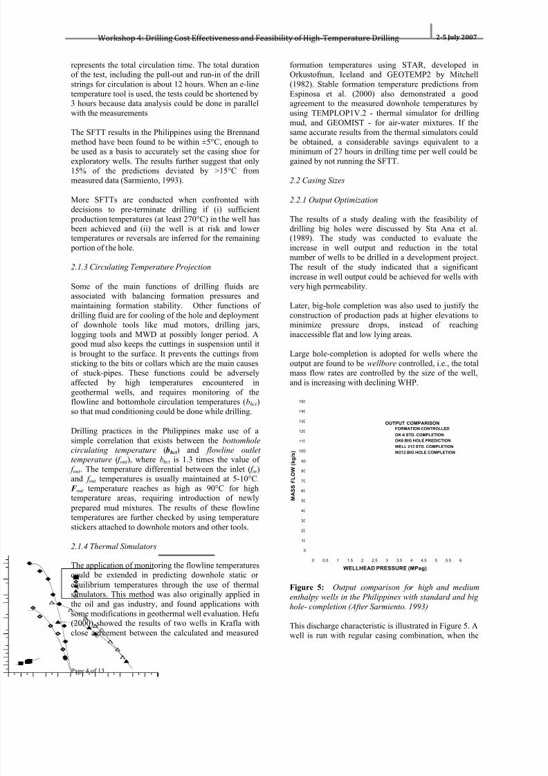
Figure 10 shows the drilling performance in thePhilippines during the last 15 years based on the variousreports by Talens et al., (1997), Southon (2003), Herrasand Jara (2006). These wells were selected to show themarked difference on the drilling performance for thevarious wells. The red and the blue squares shows thatas much as 20 days were involved in non-rotating hours(downtime) from the performance of a conventionalrotary drilling rig using mud as the main drilling fluids.The graph of the total depth vs. drilling durationindicates that there is a significant potential for
improvement in achieving faster drilling by mainlyreducing the downtime incurred during the actualdrilling, which by experience makes up 15-25 %.Furthermore, 10-17 % of this downtime could be
controlled with better planning and logistics. The blackcircles represent what could be considered as drillingrecord for completing geothermal wells in a span of 26days for 2800 meters, and less than 60 days for 3400
meter wells, by using conventional rig equipped with a portable top drive system and steerable MWD tools(Southon, 2003). Other improved drilling practices thatinvolved reducing the non-rotating hours were alsoimplemented which had significantly contributed to thenew record. This emerging performance record deviates
significantly from the unpredictable performance of past drilling results clearly shown in Figure 10.
0 10 20 30 40 50 60 70 80 90 100 110 120 130 140 150
DRILLING DURATION (days)
3600
3400
3200
3000
2800
2600
2400
2200
2000
1800
1600
1400
1200
1000
800
600
400
200
0
M E A S U R E D D E P T H
( m e t e r s )
DRILLING PERFORMANCECONVENTIONAL DRILLING WITH DOWNTIME
CONVENTIONAL DRILLING W/O DOWNTIME
CONVENTIONAL DRILLING_ONLY TOP DRIVE
HAGEN_HOLE 6 AIR DRILLING_TOP DRIVE (NZ)
THORHALLSSON_CONVENTIONAL_MUD MOTOR (Iceland)
CONVENTIONAL_AIR DRILLING_NO TOP DRIVE
Figure 10: Drilling performance results of selected
wells from the Philippines, New Zealand and Iceland.
The open diamond is a well completed in NZ using airdrilling and a top drive to supplement the conventionalrig (Hole, 2006). The black crosses represent the
0 20 40 60 80 100 120 140 160 180
DRILLING DURATION (days)
3600
3400
3200
3000
2800
2600
2400
2200
2000
1800
1600
1400
1200
1000
800
600
400
200
0
M E A S U R E D D E P T H ( m e t e
r s )
DRILLING PERFORMANCE IN THE PHILIPPINES AREA 1 VERTICAL
AREA 1 DIRECTIONAL
AREA 2 VERTICAL
AREA 2 DIRECTIONAL
AREA 2 TOP HOLES
AREA 3
AREA 4
AREA 4 LINEAR FIT
AIR DRILLING/NO TOP DRIVE
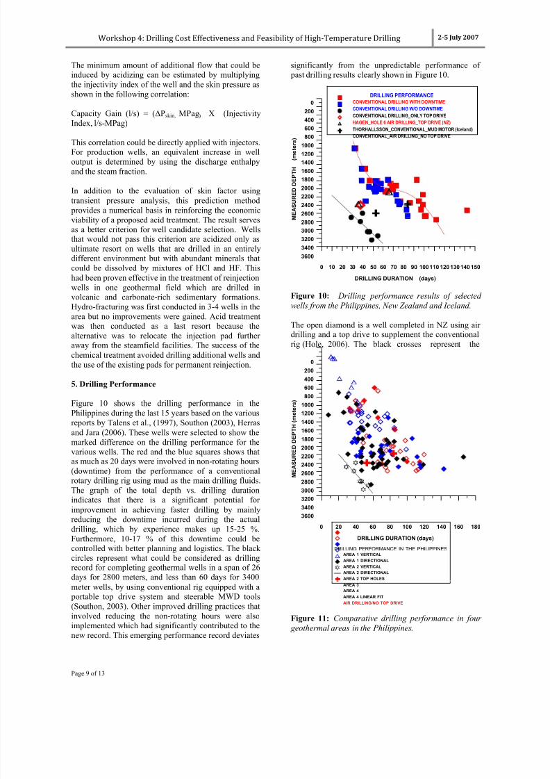
Figure 11: Comparative drilling performance in four
geothermal areas in the Philippines.

7/26/2019 A Snapshot of the Drilling and Completio n Practices in High Temperature Geothermal Wells - Sarmiento
http://slidepdf.com/reader/full/a-snapshot-of-the-drilling-and-completio-n-practices-in-high-temperature-geothermal 10/13
Workshop 4: Drilling Cost Effectiveness and Feasibility of High‐Temperature Drilling 2-5 July 2007
Page 10 of 13
performance of conventional rig in the Philippineswithout a top drive but with aerated drilling. One of thetwo wells fits linearly with this Hole (2006) in NZ. Thetwo triangles represent two wells drilled in Iceland; oneusing the conventional drilling and the other with mudmotor drilling down to TD (Thorhallsson, 2007). Thefirst well that was drilled conventionally falls within the
performance of many wells (red and blue squares);while the one drilled with mud motor all the waymatches well with that drilled with air drilling. It isclearly shown in the plot that the combination ofaerated drilling and top drive units adopted from Hole(2006) hole was not enough to match the drilling ratedemonstrated in the Philippines. The objective of usingaerated drilling in the Philippines for drilling andcompleting infill wells has been achieved with a betterdrilling rate than conventional drilling.
To further demonstrate the unpredictable drilling performance in Philippines, many wells with availableinformation were plotted in Figure 11.
6. Drilling Cost
Table 3 shows that the costs of drilling geothermalwells make up 29 % of the total investment in ageothermal project in the Philippines. These costsexclude stimulation costs. Table 3 also illustrates thesignificant increase in the recent drilling cost of wells inthe country, which had been almost unchanged from1985 to 2005 - from USD 1.91 million to USD 2.1million per well (Tolentino, 1986; Dolor, 2005; Dolor,2006). These costs are considered average; therefore,costs could be significantly lower or higher in somecases as shown in Figures 6 and 12.
Table 3: Typical Drilling Cost for a 100 MW
geothermal field in the Philippines. (See text for
reference)
Item Cost/WellMM US$
Total CostMM US$
%
Proj.Cost
Year ‘85 ‘05 ‘06 ‘85 ‘05 ‘06 ‘06
Explo. Wells 1.91 2.1 2.9 5.73 6.3 8.7 3.1
Prod/Reinj.Wells
1.91 2.1 2.9 53.5 58.8 81.2 29.3
Steamfield(WithDrilling)
88.4 115.7 136 49.1
Power PlantCost
88 140 140 50.5
Total ProjectCost
176.4 255.7 276.9 100
Explo Wells: 3 Production Wells: 21 Reinjection wells: 7
Southon (1994) indicated that drilling cost per well in1994 may not exceed USD 1.5 million while Tolentino(1986) might have indicated the upper range of the
drilling cost at USD 1.9 million. The most recentaccount in drilling cost jumped by 38% from USD 2.1million to USD 2.9 million from 2005 to 2006 (Dolor,2005; Dolor, 2006). Twenty five percent of this cost isincurred with the adoption of air drilling technique(Jumawan et al., 2006). The second major reason for theincrease is due largely to high cost of rig rental caused
by the huge demand for rigs all over the world, whichshould also be reflected by field operators owning a rig.The costs of casings and valves, which account for 9-13% of the total well costs, had recently experienceddramatic increases in prices because of strong demandfor metals as shown by Cooney (2006).
Figure 12 shows the drilling cost as a function of depthin 2006 US $. The data were extracted from KRTA(1979), Sta Ana (1997), Dolor (2005, 2006), Hole(2006) and Thorhallsson (2007).
0 400 800 1200 1600 2000 2400 2800 3200
MEASURED DEPTH (meters)
0.1
1
10
D R I L L I N G C O S T S ( M M U S $ )
DRILLING COST COMPARISON
STANDARD HOLE (1995-1996)
STANDARD HOLE (1979)
STANDARD HOLE (1994)
STANDARD HOLE (2005)
STANDARD HOLE (2006)
BIG HOLE (1995-1996)
BIG HOLE (2003-2004)
ICELAND HOLE (2006)NEW ZEALND HOLE (2006)
Figure 12: Drilling costs in the Philippines in year
2006 US $ as a function of depth. (See text for
reference)
The drilling costs in the Philippines were inflated usingthe formula cited by DOE (2007) that took into accountthe Consumer Price Indices (CPI) in the Philippines andthe USA (NSO, 2007; US Department of Labor, 2007)
the Philippine peso vis-à-vis US Dollar exchange rates,general wholesale price index of manufactured goodsand machinery, and transport equipment in the NationalCapital Region. The plot shows that the cost of drillingup to 1600 meters in 1979 (KRTA 1979) would exceedthe 2006 cost level of drilling deeper wells. Figure 12also illustrates that the costs of drilling standard holes in
New Zealand and Iceland are slightly higher than in thePhilippines.

7/26/2019 A Snapshot of the Drilling and Completio n Practices in High Temperature Geothermal Wells - Sarmiento
http://slidepdf.com/reader/full/a-snapshot-of-the-drilling-and-completio-n-practices-in-high-temperature-geothermal 11/13
Workshop 4: Drilling Cost Effectiveness and Feasibility of High‐Temperature Drilling 2-5 July 2007
Page 11 of 13
Figure 13 shows the same data points plotted with thoseof the drilling costs reported by Augustine et al. (2006).The plot shows that the costs of drilling geothermalwells in the Philippines are also higher than in oil andgas drilling, albeit within the line formed by the Cosoand Sandia wells
0 1000 2000 3000 4000 5000 6000 7000 8000 9000 10000
MEASURED DEPTH (meters)
0.1
1
10
D R I L L I N G C O S T S ( M M U S $ )
WORLDWIDE COMPARATIVEDRILLING COST
OIL AND GAS WELLS
OIL AND GAS FIT
PHILIPPINES
GEYSERS
COSO
SANDIA
SOULTS
AUSTRALIA
FENTON HILL
ROSMANOWE
CAMBORNE
Figure 13: Completed well costs in year 2003 US $ as
a function of depth (Data from other countries areextracted from Agustine et al., 2006)
The foreseen unabated increase in costs of drillingconsumables, materials, and third party services put alot of pressure on geothermal operators to improveexisting drilling practices to reduce total drilling timecompletion, and minimize the number of wells to bedrilled. It has been shown in the Philippines that such
targets could be achieved by adopting improved drilling practices, aerated drilling and use of top driveequipment.
7. Future Areas of Research
While the foregoing results already indicate significantimprovement in drilling performance, continuousinnovation in drilling technology and enhancement indrilling practices should be sustained. Failure todischarge completed wells because of crossflow anddownflow of cold fluids results in drilling of additionalwells. Handling this zone also delays significantly thedrilling operation. It should be treated immediately
during drilling with high temperature packers to preventthe occurrence of a temperature reversal and allow thetrue wellbore fluids at depth and its true temperature to
be measured i n the well.
The use of high temperature acid diverters to isolatetargeted zones during acidizing treatment operations
would prevent opening up of unwanted fractures orinjection zones that communicates directly with
production wells.
During the releasing of stuck pipes while drilling, ahigh temperature mechanical cutter would be anadvantage over the chemical or explosives cutter.
With maturing and continuing depletion of geothermalreservoirs in the Philippines, the direction in the futureis to sustain production from existing fields by drilling
at >3000 meters to tap the high temperature and high pressure geothermal fluids. It is crucial that well throwwould have to exceed currently achievable 1,300 metersto further reduce site clearing and excavations, and beable to comply with environmental rules. Very fewdownhole tools are currently available that couldwithstand what is usually the working temperature limitof 150°C during drilling. There would be frequent tripsto the surface as high temperatures wear down ondownhole motors and bit. These challenges requiretechnology innovations and superior equipment thatwould entail additional costs.
8. Conclusions
Significant improvement in drilling and completiontechnology in the Philippines has evolved over the last3 and half decades. Downhole logging andmeasurements while drilling provide the necessaryinformation where to set the casing at desiredtemperatures thereby increasing the success rate ofdrilling. The adoption of big-hole completion enablesmaximum production from productive reservoirsresulting in lesser number of wells to be drilled.
Problems associated with multi-loss zones and TLC areovercome by the use of two-liner big hole completion,HT polymer viscosifier, and aerated drilling fluids in anunder-balanced drilling operation. The use of top drivesystem had demonstrated that drilling holes deeper than3000 meters could be completed in less than 30 days,with the aid of steerable mud motors, polycrystallinediamond bits (PCD) and improvement of major drilling
practices. Drilling costs have increased significantlydue to additional equipment required in aerated drilling,top drives, and HT mud motors and bits. However, theirapplications have been instrumental in obtaining high
percentage of success in achieving drilling targets andcompleting wells. Further improvement in reducing
non-rotating hours in drilling would ensure thatcurrently achieved drilling completion of less than 30days could be maintained even at more complicateddrilling environment.
Solutions in isolating temperature reversals and cross-flow of cold fluids should be evaluated to furtherincrease the success rate of drilling.
Completion technology used in enhancing the permeability of the reservoir plays a significant role inmaximizing production and injection capacity of wells.As high as 900 % improvement in well output has beenachieved in acidizing wells, and normally non-
7/26/2019 A Snapshot of the Drilling and Completio n Practices in High Temperature Geothermal Wells - Sarmiento
http://slidepdf.com/reader/full/a-snapshot-of-the-drilling-and-completio-n-practices-in-high-temperature-geothermal 12/13
Workshop 4: Drilling Cost Effectiveness and Feasibility of High‐Temperature Drilling 2-5 July 2007
Page 12 of 13
commercial wells have been converted as productionwells. Hydro-fracturing at high pressure conditions hasalso proven to be effective in creating and establishingfracture network. These stimulation methods willcontinue to contribute significantly in reducing thenumber of wells to be drilled, especially when mud isused as the drilling fluid and in geothermal areas with
sedimentary and carbonate formations.
9. Acknowledgment
Most of the cases cited in this paper were drawn fromthe tenure of the author with PNOC EnergyDevelopment Corporation. Thanks are due to the DOEGeothermal Division for providing relevant informationand statistics.
References
Aleman, E.T., and Clotworthy, A.W. (1996): A Methodfor Estimating Capacity Increases from Acidizing Mud-Damaged Reinjection Wells, Proceedings, PNOCEDCGeothermal Conference, Makati City, Philippines,(1996).
API (1989), API Bulletin on Formulas and Calculationsfor Casing, Tubing, Drill Pipesand the Pipe Properties.American Petroleum Institute. Washington D.C., APIBulletin5C3-89, 40pp.
Augustine, C., Tester, J.W., Anderson, B., Petty, S. andLivesay, B. (2006), A Comparison of Geothermal withOil and Gas Well Drilling Costs. Proceedings: Thirty-First Workshop on Geothermal Reservoir Engineering.Stanford University, Stanford, California, January 30-February 1, 2006
Brennand, A. W. (1984), A New Method for theAnalysis of Static Formation Temperature Tests.Proceedings: 6
th NZ Geothermal Workshop 1984.
Auckland University, Auckland New Zealand.
Buning, B. C., Malate, R. C. M., Lacanilao, A. M., StaAna, F.X.M., and Sarmiento, Z. F. (1995), RecentExperiences in Acid Stimulation by PNOC EnergyDevelopment Corporation, Philippines. Proceedings:
World Geothermal Congress 1995. Florence, Italy. 18-31 May 1995.
Chillingar, G. V. and Rieke III H. H. (1962), Casing
and Tubular Design Concepts. Handbook ofGeothermal Energy.
Cooney, S. (2006), Steel: Price and Policy Issues. CRS
Report for Congress. 31 August 2006. Congressional
Research Service The Library of Congress.
Dench, N. D. (1970), Casing String Design forGeothermal Wells. Geothermics: Special Issue No.2.
DOE (2007), Geothermal Resources Sales ContractForm. March 22, 2007.http://www.doe.gov.ph/geocoal/Mt_Apo%20Geo%20Project/PNOC%20EDC%20SSA.pdf
Dolor, F. M. (2005), Phases of geothermal developmentin the Philippines. Proceedings: Workshop for Decision
Makers on Geothermal Projects and their Management.Organized by UNU-GTP and KenGen, held at NaivashaSimba Lodge, Lake Naivasha, Kenya, 14-18 November2005.
Dolor, F. M. (2006), Phases of GeothermalDevelopment in the Philippines. Proceedings:Workshop for Decision Makers on Geothermal Projectsin Central America, Organized by UNU-GTP and LaGeo in San Salvador, El Salvador, 26 November to 2December 2006.
Dowdle, W. L. and Cobb, W. M. (1975), StaticFormation Temperatures from Well Logs. Journal ofPetroleum Technology. November 1975. pp. 1326-1330
Edwardson, M.J., Girner, H.J., Parkison, H.R.,Williamson, C.D., and Matthews, C.S., (1962),Calculation of Formation Temperature DisturbancesCaused by Mud Circulation," J.Pet.Eng. (April 1962),416-426; Trans. AIME, 225.
Espinosa, G., García, A., Hernández, I., and Santoyo, E.(2000), Comparative Study of Thermal Behavior duringDrilling of Geothermal Wells Using Mud and Air-Water as Drilling Fluids. Proceedings: WorldGeothermal Congress 2000. Kyushu-Tohoku, Japan.May 28-10 June 2000.
Golla, G. U. and Haas, T. R. (1998), Forked HoleCompletion at Tiwi. Proceedings: 19th Annual PNOC-EDC Geothermal Conference. New World Hotel,Makati City, Philippines. 5-6 March 1998)
Golla, G. U., Sevilla. E. P., Bayrante, L. F., Ramos, S.G. and Taganas, R.G., (2006), Geothermal EnergyExploration and Development in the Philippines after35 years. Proceedings: 28th NZ Geothermal Workshop
2006. Auckland, New Zealand.
Hefu, H. (2000), Study on deep Geothermal Drillinginto a Supercritical Zone in Iceland. The United Nations
University, Reports 2000, Number 7.
Hole, H. (2006), Aerated Fluids for Drilling ofGeothermal Wells. United Nations University.
Geothermal Training Programme. Sept 2006.Orkustofnun- National Energy Authority, Iceland.
Horton, R. M., Minette, T. N., Budd, C. F., Alcaraz, A.P. and Jovellanos, J. U. (1981), CommercialDevelopment of Tiwi and Mak-Ban Fields in the

7/26/2019 A Snapshot of the Drilling and Completio n Practices in High Temperature Geothermal Wells - Sarmiento
http://slidepdf.com/reader/full/a-snapshot-of-the-drilling-and-completio-n-practices-in-high-temperature-geothermal 13/13
Workshop 4: Drilling Cost Effectiveness and Feasibility of High‐Temperature Drilling 2-5 July 2007
Page 13 of 13
Philippines. Proceedings: ASEAN Council onPetroleum 2nd Conference and Exhibition (ASCOPE81), Manila, October 7-11, 1981.
KRTA (1979), The Tongonan Geothermal Field, Leyte,Philippines. Report on Exploration and Development.September 1979.
http://www.osti.gov/bridge/servlets/purl/5166037-JcmzZz/webviewable/5166037.pdf March 22, 2007.
Malate, R.C. M., Yglopaz, D. M., Austria, J. J. C.,Lacanilao, A. M., and Sarmiento, Z. F. (1997), AcidStimulation of Injection Wells in the Leyte GeothermalPower Project, Philippines. Proceedings: TwentySecond Workshop on Geothermal ReservoirEngineering. Stanford University, Stanford California.27-29 January 1997.
Messer, P. H. (1976), Estimation of Static ReservoirTemperature during Drilling Operations. Proceedings:First Workshop on Geothermal Reservoir Engineering.Stanford University, Stanford California. 1976.
Mitchell, R. F. (1982), Advanced Wellbore ThermalSimulator GEOTEMP2. Research Report, 1982.Enertech Engineering and Research Co. USA. SAND -82-7003/1
New Zealand Standard (1991). Code of Practice forGeothermal Wells. Standard Association of NewZealand.
NSO (2007), CPI in the Philippines. Compilation ofEconomic Indices in CD. National Statistics Office,Ramon Magsaysay, Sta Mesa. Manila.
Raymond, L. R. (1969), Temperature Distribution in aCirculating Drilling Fluid. Journal of PetroleumTechnology, 333-341.
Roux, B., Sanyal, S. K., and Brown, S., (1979), AnImproved Approach to Estimating True ReservoirTemperature from Transient Temperature Data. 1979Workshop on Geothermal Reservoir Engineering.Stanford University, Stanford California
Sarmiento, Z. F. (1993), Geothermal Development inthe Philippines. Lectures Delivered at UNU GeothermalTraining Programme. Orkustofnun, Reykjavik, Iceland,Report 2, 1993.
Sarmiento, Z. F. (2000), Physical Monitoring II: HighEnthalpy Geothermal Systems. Course Proceedings:
Long Term Monitoring of High and Low EnthalpyFields Under Exploitation. WGC 2000 Short Courses.Kokonoe, Kyushu District, Japan. pp. 50-51.
Sta Ana., F. X. M., Sarmiento, Z. F., Saw, V. S., Salera,J. R. M. and Retuya, R. E. (1997), Results of LargeDiameter Well Drilling in Philippine Geothermal Wells.Proceedings: Twenty-First Workshop on GeothermalReservoir Engineering. Stanford University, StanfordCalifornia. 27-29 January 1997.
Southon, J.N.A., and Gorbachev, G. (2003), DrillingGeothermal Wells Efficiently, with Reference to theMutnovsky, Mak-Ban and Lihir Geothermal Fields.Proceedings: NZ Geothermal Workshop 2003.Auckland, New Zealand.
Talens, M. A., Herras, C. and Ogena, M.S. (1997),Keys to Successful Drilling in Mahanagdong.Proceedings: Twenty-Third Workshop on GeothermalReservoir Engineering. Stanford University, StanfordCalifornia. 26-28 January 1998.
Thorhallsson, S., Matthiasson, M., Gislason, T.,Ingason, K., Palsson. B., Fridleifsson., G. (2003),Iceland Deep Drilling Project: Part II DrillingTechnology. IDDP Drilling Feasibility Report. Iceland.May 2003.
Thorhallsson, S. (2007), Developments in GeothermalDrilling. ENGINE Mid-Term Conference, 10-12January 2007, Potsdam, Germany.
Tolentino, B. S. (1986), Lectures on GeothermalEnergy in the Philippines. UNU Geothermal TrainingProgramme. Orkustofnun, Reykjavik, Iceland, Report12, 1986
U. S. Department of Labor (2007).Bureau of Labor Statistics Consumer Price Indexes.2March2007http://www.bls.gov/cpi/home.htm#data
Yglopaz, D. M., Austria, J. J. C., Malate, R. C. M.,Buning, B. C., Sta Ana, F. X. M., Salera, J. R. M., andSarmiento, Z. F., (2000), A Large Scale WellStimulation Campaign at Mahanagdong GeothermalField (Tongonan), Philippines. Proceedings: WorldGeothermal Congress 2000. Kyushu-Tohoku, Japan.May 28-10 June 2000.